JP2004110012A - Image forming apparatus, cartridge, and storage medium - Google Patents
Image forming apparatus, cartridge, and storage medium Download PDFInfo
- Publication number
- JP2004110012A JP2004110012A JP2003302521A JP2003302521A JP2004110012A JP 2004110012 A JP2004110012 A JP 2004110012A JP 2003302521 A JP2003302521 A JP 2003302521A JP 2003302521 A JP2003302521 A JP 2003302521A JP 2004110012 A JP2004110012 A JP 2004110012A
- Authority
- JP
- Japan
- Prior art keywords
- image forming
- cartridge
- forming apparatus
- main body
- image
- Prior art date
- Legal status (The legal status is an assumption and is not a legal conclusion. Google has not performed a legal analysis and makes no representation as to the accuracy of the status listed.)
- Granted
Links
Images
Classifications
-
- G—PHYSICS
- G03—PHOTOGRAPHY; CINEMATOGRAPHY; ANALOGOUS TECHNIQUES USING WAVES OTHER THAN OPTICAL WAVES; ELECTROGRAPHY; HOLOGRAPHY
- G03G—ELECTROGRAPHY; ELECTROPHOTOGRAPHY; MAGNETOGRAPHY
- G03G21/00—Arrangements not provided for by groups G03G13/00 - G03G19/00, e.g. cleaning, elimination of residual charge
- G03G21/16—Mechanical means for facilitating the maintenance of the apparatus, e.g. modular arrangements
- G03G21/18—Mechanical means for facilitating the maintenance of the apparatus, e.g. modular arrangements using a processing cartridge, whereby the process cartridge comprises at least two image processing means in a single unit
- G03G21/1875—Mechanical means for facilitating the maintenance of the apparatus, e.g. modular arrangements using a processing cartridge, whereby the process cartridge comprises at least two image processing means in a single unit provided with identifying means or means for storing process- or use parameters, e.g. lifetime of the cartridge
- G03G21/1878—Electronically readable memory
- G03G21/1889—Electronically readable memory for auto-setting of process parameters, lifetime, usage
-
- G—PHYSICS
- G03—PHOTOGRAPHY; CINEMATOGRAPHY; ANALOGOUS TECHNIQUES USING WAVES OTHER THAN OPTICAL WAVES; ELECTROGRAPHY; HOLOGRAPHY
- G03G—ELECTROGRAPHY; ELECTROPHOTOGRAPHY; MAGNETOGRAPHY
- G03G15/00—Apparatus for electrographic processes using a charge pattern
- G03G15/14—Apparatus for electrographic processes using a charge pattern for transferring a pattern to a second base
- G03G15/16—Apparatus for electrographic processes using a charge pattern for transferring a pattern to a second base of a toner pattern, e.g. a powder pattern, e.g. magnetic transfer
Landscapes
- Physics & Mathematics (AREA)
- General Physics & Mathematics (AREA)
- Engineering & Computer Science (AREA)
- Computer Vision & Pattern Recognition (AREA)
- Control Or Security For Electrophotography (AREA)
- Electrophotography Configuration And Component (AREA)
Abstract
【課題】 仕様の異なる複数種の画像形成装置本体で互換性のあるカートリッジを、仕様の異なる本体間にそれぞれ装着しても、その本体に対応した交換時期を正確に把握することを可能にする。
【解決手段】 カートリッジの記憶部に、仕様の異なる画像形成装置本体における使用量に関する情報を各々記憶し、これらの情報を用いて、カートリッジの交換時期を判断する画像形成装置。
【選択図】 図3PROBLEM TO BE SOLVED: To accurately grasp a replacement time corresponding to a main body of a plurality of types of image forming apparatuses even if cartridges compatible with the main body of different specifications are mounted between the main bodies of different specifications. .
SOLUTION: An image forming apparatus in which information relating to an amount of use in an image forming apparatus main body having different specifications is stored in a storage section of a cartridge, and a replacement time of the cartridge is determined using the information.
[Selection diagram] FIG.
Description
本発明は、電子写真方式の複写機、レーザビームプリンタ等の画像形成装置および画像形成装置に着脱可能なカートリッジに関するものである。 The present invention relates to an image forming apparatus such as an electrophotographic copying machine and a laser beam printer, and a cartridge detachable from the image forming apparatus.
電子写真記録方式を用いた既知の画像形成装置として、例えば、レーザビームプリンタは、回転駆動される像担持体としての感光ドラム、感光ドラムの表面を一様に帯電する帯電手段としての帯電ローラ、感光ドラムの表面を露光して画像信号に対応した静電潜像を形成させるレーザ、静電潜像をトナーにより現像して可視画像を形成させる現像手段、可視画像(現像剤像)をシートとしての記録用紙上に転写させる転写ローラ、記録用紙上に転写された可視画像を定着させる定着手段、クリーニング手段等、を具備している。 As a known image forming apparatus using an electrophotographic recording method, for example, a laser beam printer is a photosensitive drum as an image carrier that is driven to rotate, a charging roller as a charging unit that uniformly charges the surface of the photosensitive drum, A laser for exposing the surface of the photosensitive drum to form an electrostatic latent image corresponding to an image signal, developing means for developing the electrostatic latent image with toner to form a visible image, and a visible image (developer image) as a sheet And a fixing unit for fixing the visible image transferred on the recording paper, a cleaning unit, and the like.
この画像形成装置において、感光ドラムと帯電ローラとを、クリーニング手段や現像手段と一体的にカートリッジ化して、このカートリッジ化したもの(以下、プロセスカートリッジという。)を着脱可能とすることにより、メンテナンスフリーの画像形成装置を実現したものが知られている。 In this image forming apparatus, the photosensitive drum and the charging roller are formed into a cartridge integrally with the cleaning means and the developing means, and the cartridge (hereinafter referred to as a process cartridge) is detachable, thereby being maintenance-free. Is realized.
このような画像形成装置では、例えば長期使用により、プロセスカートリッジに組込まれた構成部品の機能が低下した場合、プロセスカートリッジ全体が交換されている。 In such an image forming apparatus, if the functions of the components incorporated in the process cartridge are deteriorated due to, for example, long-term use, the entire process cartridge is replaced.
この交換作業は、ワンタッチで画像形成装置本体を開放して、画像形成装置本体内部から古いプロセスカートリッジを取り出し、画像形成装置本体に未使用新品のプロセスカートリッジを装着するといった極めて簡単な作業であり、操作者自身で容易に実施することができるものである。 This replacement operation is a very simple operation of opening the image forming apparatus main body with one touch, taking out an old process cartridge from the inside of the image forming apparatus main body, and mounting a new unused process cartridge in the image forming apparatus main body, This can be easily implemented by the operator himself.
このプロセスカートリッジの寿命(交換時期)は主に、感光ドラムや現像ローラの摩耗とトナーの消費で決定される。感光ドラムや現像ローラの摩耗は、概略、それらの総回転数により算出できる。そこで、総回転数に比例する総プリント枚数で寿命(交換時期)を算出することができる。また、トナーの消費はトナー残量検知手段により、検知することができる。 寿命 The life (replacement time) of this process cartridge is mainly determined by the wear of the photosensitive drum and the developing roller and the consumption of toner. The wear of the photosensitive drum and the developing roller can be roughly calculated from the total number of rotations thereof. Therefore, the life (replacement time) can be calculated from the total number of prints proportional to the total number of rotations. Further, the toner consumption can be detected by the toner remaining amount detecting means.
トナー残量はその都度検知することができる。しかし、プロセスカートリッジはユーザが任意に交換できるため、感光ドラムや現像ローラの寿命に関する総プリント枚数は、プロセスカートリッジに保管されることが望ましい。 Toner remaining amount can be detected each time. However, since the user can arbitrarily replace the process cartridge, it is desirable that the total number of prints relating to the life of the photosensitive drum and the developing roller be stored in the process cartridge.
例えば、従来からプロセスカートリッジに装着されたメモリに寿命情報を記憶する方法が知られている。 For example, a method of storing life information in a memory mounted on a process cartridge is conventionally known.
一方、異なる仕様(種類)の画像形成装置であっても、単に1分間にプリントできる枚数のみ異なる場合は、プロセスカートリッジを共通としていることがある。新製品として画像形成装置が発売される度にプロセスカートリッジを変更していたのでは、生産面でのコストアップ、更には販売面でプロセスカートリッジの保管場所が機種毎に必要となってしまう。そこで、消耗品であるプロセスカートリッジは、なるべく共通化することが望ましい。 On the other hand, even if the image forming apparatuses have different specifications (types), if only the number of sheets that can be printed in one minute is different, the process cartridge may be common. If the process cartridge is changed every time the image forming apparatus is released as a new product, the cost of production increases and the storage location of the process cartridge becomes necessary for each model in terms of sales. Therefore, it is desirable that the process cartridges that are consumables be shared as much as possible.
また、1分間にプリントできる枚数を異ならせる方法は、一般に、2通りある。プリント枚数を早めるには、感光ドラムの回転スピードそのものを上げる方法と、連続プリント中の紙と紙の間隔を狭める方法である。この紙と紙の間隔を単に紙間と呼ぶことにする。 {Circle around (2)} There are generally two ways to vary the number of prints per minute. To increase the number of prints, there are a method of increasing the rotation speed of the photosensitive drum itself and a method of narrowing the interval between papers during continuous printing. This space between papers will be simply referred to as a paper interval.
感光ドラムの回転スピードを上げた場合、この本体は回転スピードがそのままの本体と比較して、総回転数と総プリント枚数の関係は変わらない。これは単位時間当たりの回転数が多くなった分に比例してプリント枚数が増えるためである。 (4) When the rotation speed of the photosensitive drum is increased, the relationship between the total number of rotations and the total number of prints does not change in this main body compared to the main body having the same rotation speed. This is because the number of prints increases in proportion to the increase in the number of rotations per unit time.
従って、総回転数に関係する総プリント枚数をメモリに記憶しておけば、印刷スピードの異なる本体間であっても、従来の算出方法でも、感光ドラムや現像ローラ等の寿命(交換時期)を正しく算出することができる。 Therefore, if the total number of prints related to the total number of rotations is stored in the memory, the life (replacement time) of the photosensitive drum, the developing roller, and the like can be reduced by the conventional calculation method even between the main units having different printing speeds. It can be calculated correctly.
一方、紙間を縮める方法は、感光ドラムの回転スピードが、それぞれの本体間で等しく、紙の搬送スピードも等しい。従って、レーザ照射条件や定着条件等の画像にかかわる諸条件を一定にできるため、短期間で開発できるだけでなく、各部品を共通化できるため、コストや部品の信頼性を上げることができる。 On the other hand, in the method of shortening the paper interval, the rotation speed of the photosensitive drum is equal between the main bodies, and the paper transport speed is also equal. Accordingly, since various conditions relating to the image such as laser irradiation conditions and fixing conditions can be kept constant, not only can development be performed in a short period of time, but also each component can be shared, so that cost and reliability of components can be increased.
しかしながら、紙間を縮めて単位時間(1分間)当りのプリント枚数を異ならせた場合、異なる仕様の画像形成装置夫々の本体間では、感光ドラムや現像ローラ等の総回転数と総プリント枚数の関係が異なってしまう。紙間を狭めた本体は紙間がそのままの本体と比較して、画像を印字していない紙間の時間の割合が短くなる。つまり、印刷に寄与する時間の比が増えるため、同じ総回転数に対して、紙間が短い本体ほど総プリント枚数が多くなるのである。 However, if the number of prints per unit time (one minute) is made different by shortening the sheet interval, the total number of rotations of the photosensitive drum and the developing roller and the total number of prints between the main bodies of the image forming apparatuses of different specifications are different. Relationships are different. In a main body having a reduced paper interval, the ratio of time between papers on which no image is printed is shorter than a main body in which the paper interval is unchanged. That is, since the ratio of the time that contributes to printing increases, the total number of prints increases as the body length is shorter for the same total number of rotations.
したがって、感光ドラムや現像ローラの寿命(交換時期)を算出する場合、紙間の異なる本体間では、従来の算出方法ではうまく行かない。 Therefore, when calculating the service life (replacement time) of the photosensitive drum or the developing roller, the conventional calculation method does not work well between the main units having different paper intervals.
そこで、紙間が長い方の本体に、総印字枚数の閾値の設定を一律に揃えてしまう方法もある。しかし、紙間を短くした本体で多めに印刷できるにもかかわらず、互換性のある紙間の長い本体に合わせて寿命を短くしなければならず、有効な策とは言えない。特に、感光ドラムが摩耗して寿命を越えた場合は、画像形成装置の寿命ランプを点灯させ、印刷をいったん、停止させ、ユーザーにプロセスカートリッジの交換を促すことが望ましい。感光ドラムの寿命で本体をいったん停止させる理由は、寿命を越えた感光ドラムが原因で、定着器内での巻き付きやジャム等の本体にダメージを与えるような画像不良の発生を事前に防ぐためである。 Therefore, there is a method of uniformly setting the threshold value of the total number of printed sheets on the main body having a longer sheet interval. However, despite the fact that a large amount of printing can be performed with a main body having a short paper interval, the life must be shortened in accordance with a long main body having a compatible paper interval, which is not an effective measure. In particular, when the life of the photosensitive drum is exceeded due to wear, it is desirable to turn on the life lamp of the image forming apparatus, temporarily stop printing, and urge the user to replace the process cartridge. The reason for temporarily stopping the main unit during the life of the photosensitive drum is to prevent the occurrence of image defects such as wrapping in the fixing unit or damage to the main unit such as jams due to the photosensitive drum that has exceeded its life. is there.
また、ユーザにおいては、紙間が短い本体と紙間が長い本体の2種類を両方所有している場合がある。プロセスカートリッジに互換性があれば、同一のプロセスカートリッジを両方の本体に、代わる代わる装着する可能性がある。この場合、片方の本体で寿命を迎え、他方の本体で寿命が未達であるといった、不合理が発生する場合がある。 ユ ー ザ Furthermore, a user may have both a main body having a short paper interval and a main body having a long paper interval. If the process cartridges are compatible, there is a possibility that the same process cartridge is alternately mounted on both bodies. In this case, irrationality may occur such that one of the main bodies reaches the end of its life and the other main body has not reached the end of its life.
本発明は、以上のような問題点に鑑みて為されたものであり、その目的とする処は、仕様の異なる種類の本体に対して互換性のある着脱可能なカートリッジの寿命(交換時期)を正確に把握することにある。 SUMMARY OF THE INVENTION The present invention has been made in view of the above-described problems, and an object thereof is to provide a service life (replacement time) of a detachable cartridge compatible with a main body of a different type. Is to grasp exactly.
また、それぞれ仕様の異なる本体において互換性のある着脱可能なカートリッジの寿命(交換時期)を正確に判断することにある。 Another object of the present invention is to accurately determine the life (replacement time) of a removable cartridge that is compatible with a body having different specifications.
このため、本発明においては、下記に示す画像形成装置及びプロセスカートリッジ、カートリッジに搭載される記憶媒体を提供することにより、前記目的を達成しようとするものである。 Therefore, in the present invention, the object is achieved by providing the following image forming apparatus, process cartridge, and storage medium mounted on the cartridge.
本発明の画像形成装置は、少なくとも画像形成に必要な部材の一部と記憶部を有し、仕様の異なる画像形成装置に対し着脱可能なカートリッジが装着される装着部と、
前記記憶部に記憶された情報に応じて前記カートリッジの交換時期を判断する制御部とを有し、
前記記憶部は前記装置の各仕様での使用量に関する情報を各々記憶する記憶領域を有し、
前記制御部は、前記記憶部の記憶領域に記憶された前記各仕様での使用量情報に応じて前記カートリッジの交換時期を判断することを特徴とする。
The image forming apparatus of the present invention has at least a part of members necessary for image formation and a storage unit, and a mounting unit in which a detachable cartridge is mounted to an image forming apparatus having different specifications.
A control unit that determines a replacement time of the cartridge according to the information stored in the storage unit,
The storage unit has a storage area for storing information on the usage amount in each specification of the device,
The control unit determines a replacement time of the cartridge in accordance with the usage information in each of the specifications stored in the storage area of the storage unit.
本発明のカートリッジは、少なくとも画像形成に必要な部材の一部と記憶部とを有し、前記記憶部に記憶された情報に応じて前記カートリッジの交換時期を判断する制御部を有する仕様の異なる画像形成装置の装着部に着脱可能なカートリッジであって、
前記記憶部は、各仕様での使用量に関する情報を各々記憶する記憶領域を有することを特徴とする。
The cartridge of the present invention has at least a part of members necessary for image formation and a storage unit, and has a control unit that determines a replacement time of the cartridge according to information stored in the storage unit. A cartridge detachable from a mounting portion of the image forming apparatus,
The storage unit has a storage area for storing information on a usage amount in each specification.
本発明の記憶媒体は、少なくとも画像形成に必要な部材の一部と記憶部とを有し、仕様の異なる画像形成装置の装着部に着脱可能なカートリッジに搭載される記憶媒体であって、
前記記憶媒体には、各仕様での使用量に関する情報を各々記憶する記憶領域を有することを特徴とする。
The storage medium of the present invention has at least a part of members necessary for image formation and a storage unit, and is a storage medium mounted on a cartridge that is detachable from a mounting unit of an image forming apparatus having different specifications.
The storage medium has a storage area for storing information on a usage amount in each specification.
以上で説明したように、互換性のあるカートリッジが、それぞれ仕様の異なる本体に挿入されたときに、その本体での使用量情報をカートリッジに設けられた記憶媒体に記憶して、それぞれ使用の異なる本体に装着されて使用されても正確にカートリッジの寿命(交換時期)を把握することができる。 As described above, when compatible cartridges are inserted into the main bodies having different specifications, the usage amount information of the main bodies is stored in the storage medium provided in the cartridge, and the different usages of the main body are used. Even when the cartridge is used while being mounted on the main body, the life (replacement time) of the cartridge can be accurately grasped.
また、互換性のあるカートリッジが、それぞれ仕様の異なる本体に挿入されたときの各々の使用量情報をカートリッジに設けられた記憶媒体に記憶し、カートリッジが装着されている本体自身の使用量と自身以外の使用量とからカートリッジの寿命(交換時期)を正確に判断することが可能となる。 In addition, when a compatible cartridge is inserted into a main unit having a different specification, the usage information is stored in a storage medium provided in the cartridge. It is possible to accurately determine the life (replacement time) of the cartridge from the usage amount other than the above.
また、それぞれ異なる本体に対する寿命の上限に対応する閾値もカートリッジの記憶媒体に記憶し、互換性のあるプロセスカートリッジにおいて、異なる種類の本体に対しても、その本体に対応した寿命(交換時期)を正確に判断することができる。 In addition, the threshold values corresponding to the upper limits of the lifespans of the different main bodies are also stored in the storage medium of the cartridge, and the lifespan (replacement time) corresponding to the main bodies of different types in the compatible process cartridges is also stored. It can be determined accurately.
また、カートリッジが寿命(交換時期)であることを示す履歴情報もカートリッジの記憶媒体に記憶して、カートリッジが装着されたときに、即座に寿命(交換時期)判定を行うことができる。 Also, history information indicating that the life of the cartridge (replacement time) is stored in the storage medium of the cartridge, and the life (replacement time) can be immediately determined when the cartridge is mounted.
以下、本発明の実施の形態を、図面に基づいて詳細かつ具体的に、インライン方式のカラープリンタの実施例を用いて説明する。 Hereinafter, embodiments of the present invention will be described in detail and specifically with reference to the drawings, using examples of an inline color printer.
なお、以下の実施例に記載されている構成はあくまでも一例であり、本発明の範囲をそれらのみに限定するものではない。 The configurations described in the following embodiments are merely examples, and do not limit the scope of the present invention.
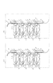
図1は、本発明の実施例1にかかる電子写真プロセスを利用したカラー画像形成装置の画像形成部の概略構成を示す断面図である。 FIG. 1 is a cross-sectional view illustrating a schematic configuration of an image forming unit of a color image forming apparatus using an electrophotographic process according to a first embodiment of the present invention.
画像形成装置101と画像形成装置102は装置構成は同じであるが、仕様のことなる画像形成装置である。この場合は搬送される紙Pの間隔が101と102で異なっている。
The
1は、像担持体である回転ドラム型の電子写真感光体(以下、感光ドラムという)、2は、帯電手段である1次帯電ローラ、3はクリーニング手段、4はクリーニング容器、5は、転写手段である転写ローラ、6は現像器、9はテンションローラである。また、71〜74は、不揮発性メモリであるカートリッジメモリ、81〜84は、感光ドラム1と、1次帯電ローラ2と、クリーニング手段3と、クリーニング容器4と、現像器6と、カートリッジメモリ71〜74とを有するプロセスカートリッジ、111、112、113、114はプロセスカートリッジ81〜84を装着するための装着部である。101と102はそれぞれ仕様の異なる別種の画像形成本体、Pは転写材である。
1 is a rotating drum type electrophotographic photosensitive member (hereinafter, referred to as a photosensitive drum) as an image carrier, 2 is a primary charging roller as a charging unit, 3 is a cleaning unit, 4 is a cleaning container, 5 is a transfer unit. A transfer roller as means, 6 is a developing device, and 9 is a tension roller.
同図において、画像形成装置101、102は、下から順に、縦一列に配置されたY(イエロー),M(マゼンタ),C(シアン),K(ブラック)の画像形成ユニットとして、転写部材としての転写ローラ5とを備え、転写ベルト10で転写材Pを搬送し、トナー画像を転写ローラ5で転写ベルト10を介して転写することにより、転写材P上にフルカラー画像を形成する構成となっている。
In FIG. 1,
ここで、それぞれ、プロセスカートリッジ81〜84と転写ローラ5とによって構成され、画像担持体として繰り返し使用されると共に、図の反時計方向に所定の周速度(プロセススピード)をもって回転駆動される感光ドラム1と、感光ドラム1の表面を一様に帯電処理する1次帯電ローラ2と、感光ドラム1上に形成された静電潜像を現像する現像装置である現像器6と、感光ドラム1上を露光して静電潜像を形成する図示していない画像露光手段と、感光ドラム1上のトナーを取り除くクリーニング手段3とを備えている。
Here, each of the photosensitive drums is constituted by the process cartridges 81 to 84 and the transfer roller 5, is repeatedly used as an image carrier, and is driven to rotate at a predetermined peripheral speed (process speed) counterclockwise in the drawing. 1, a primary charging roller 2 for uniformly charging the surface of the
画像形成装置101、102にはプロセスカートリッジ81〜84を装着するための装着部111〜114有しており、プロセスカートリッジはその装着部に対して着脱可能な構成となっている。
The
なお、本実施の形態において、感光ドラム1は直径30mmの負帯電OPC感光体であり、その周速度は90mm/secである。
In the present embodiment, the
また、1次帯電ローラ2は、感光ドラム1に従動当接して帯電を行うAC接触帯電方式の帯電装置を構成し、2000Vpp、1000Hzの交流電圧成分と−600vのDC電圧成分を重畳したバイアスを印加した1次帯電ローラ2により感光ドラム1の表面は−600vに帯電される。
Further, the primary charging roller 2 constitutes a charging device of an AC contact charging system that performs charging by being driven and contacted with the
また、現像器6は、図1に示すように内部にY,M,C,BKの磁性体を含まない、所謂ノンマグトナー(非磁性トナー)が収納されるトナー収納部と、不図示の回転駆動装置によって感光ドラム1に対して順方向に回転する現像ローラとを備え、不図示のコントローラの信号によって現像ローラに可変電圧を印加する接触一成分接触現像方式によって感光ドラム1上に形成された静電潜像を現像するものであって、感光ドラム1と対向するように配設されている。
Further, as shown in FIG. 1, the developing
また、不図示の画像露光手段は、レーザダイオード、ポリゴンスキャナ、レンズ群等によって構成されるものであり、この画像露光手段からの画像露光を受けることにより、感光ドラム1上には、それぞれ目的のカラー画像の第1〜第4の色成分像(例えばイエロー、マゼンダ、シアン、ブラック成分像)に対応した静電潜像が形成される。 The image exposure means (not shown) is constituted by a laser diode, a polygon scanner, a lens group, and the like. Upon receiving image exposure from the image exposure means, the image exposure means An electrostatic latent image corresponding to the first to fourth color component images (for example, yellow, magenta, cyan, and black component images) of the color image is formed.
なお、本実施例においては、画像露光手段はレーザダイオードを用いたポリゴンスキャナである。 In the present embodiment, the image exposing means is a polygon scanner using a laser diode.
また、レーザ露光の書き出しは、主走査方向(転写材の進行と直交方向)では走査ライン毎にBDと呼ばれるポリゴンスキャナ内の位置信号から、副走査方向(転写材の進行方向)では搬送路内のスイッチを起点とするTOP信号から、所定の時間遅延させて行う事によって、常に転写材P上の同じ位置に転写できるように、タイミングを合わせて感光ドラム1に露光を行うことができる構成となっている。
In addition, writing of laser exposure is performed based on a position signal in a polygon scanner called a BD for each scanning line in the main scanning direction (a direction orthogonal to the advance of the transfer material) and in a transport path in the sub-scan direction (the advance direction of the transfer material). A predetermined time delay from the TOP signal starting from the switch of (1), exposure can be performed on the
そして、本実施例においては、画像形成装置は接地面積を最小化するため、カートリッジを縦に配置している。カートリッジ交換やジャム処理を行う場合には、前扉(図示せず)のみを開閉する。前扉は転写ベルト10とともに開閉される構成となっている。
In the present embodiment, the cartridge is vertically arranged in the image forming apparatus in order to minimize the contact area. When performing cartridge replacement or jam clearance, only the front door (not shown) is opened and closed. The front door is configured to be opened and closed together with the
この転写ベルト10は通紙時には、転写材Pを介して感光ドラム1に当接している。
The
次に、図2を用いて、画像形成装置本体101と画像形成装置本体102の違いを説明する。図2は図1の画像形成装置本体101と102の違いを説明するために本体を模式的に示した図である。これらの本体は1分間にプリントできる枚数がことなる。画像形成本体101は、1分間に12枚プリントできる。これを12ppm(prints per minute)の本体という。一方、102は1分間に16枚プリントできる。これを16ppm(prints per minute)という。両者の転写材Pの経路について説明する。給紙ローラで給紙された転写材Pは上方に移動する。そして、下から第1色目(Y)の感光ドラム1に形成されたトナー像が、転写ローラ5を介して転写ベルト10に搬送されつつ、転写材Pに転写される。第2〜4色目のM、C、BKでも同様に、感光ドラム1上のトナー像が、順次重なりつつ転写されていく。最後に不図示の定着手段に導かれ、カラー画像がプリントされる。
Next, the difference between the image forming apparatus
ここで、転写材Pと転写材Pの間隔を紙間Wと呼び、紙間Wは本体101で150mm、本体102で40mmである。本体102では、給紙の構成や定着器の温調を工夫することにより、この紙間Wを縮めている。具体的には、給紙の構成では紙の先端位置の精度や先端位置のセンサーの応答周期を上げることで、紙間Wを縮めた。また、定着器では温調シーケンスを変更し、耐熱グレードを良くすることで紙間で加圧ローラを暖めなくても定着できるようにして、紙間Wを縮めた。
Here, the interval between the transfer materials P is referred to as a sheet interval W, and the sheet interval W is 150 mm in the
一方、感光ドラムは、その回転数に比例して摩耗することが知られている。本体102は紙間Wを短くできたので、単位枚数当たりの感光ドラムの回転数を減らすことができ、感光ドラムの寿命をのばすことができる。
A4縦の紙297mmであれば、1枚当たりに必要な長さは、
本体 101 297+W=297+150=447mm・・・・(1)
本体 102 297+W=297+ 40=337mm・・・・(2)
であり、感光ドラムの寿命は447mm÷337mm=1.33倍・・・(3)延ばすことができる。
On the other hand, it is known that the photosensitive drum wears in proportion to the number of rotations. Since the paper interval W of the
If A4 vertical paper is 297mm, the length required for one sheet is
The life of the photosensitive drum can be extended by 447 mm ÷ 337 mm = 1.33 times (3).
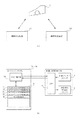
次に図3(a),(b)を用いて、画像形成装置の本体制御部と、カートリッジメモリとについて説明する。 Next, the main body control unit of the image forming apparatus and the cartridge memory will be described with reference to FIGS.
図3(a)はカートリッジCが画像形成装置101と画像形成装置102のどちらにも装着可能であることを示している。
FIG. 3A shows that the cartridge C can be mounted on both the
図3(b)は、カートリッジメモリ部71〜74と画像形成装置本体の制御部(CPU)との関係を示すブロック図である。
FIG. 3B is a block diagram showing the relationship between the
まず、カートリッジメモリ部を説明する。メモリ制御部20にはデータを記憶する為の記憶素子Mと記憶素子Mに対してデータを読み出し及び書き込みを制御するメモリ制御部20とを有している。記憶素子Mとしては不揮発性のメモリであればよく、例えばNVRAM、EEPROM、FeRAMなどを用いることが可能である。
First, the cartridge memory unit will be described. The
この記憶素子Mには、仕様の異なる画像形成装置本体101と102それぞれの為の記憶領域が設けられている。記憶領域としては、仕様の異なる本体101用の使用量情報(記録枚数)記憶領域11、仕様の異なる本体101用の最大使用量(記録枚数)閾値記憶領域12、仕様の異なる本体102用の使用量情報(記録枚数)記憶領域21、仕様の異なる本体102用の最大使用量情報(記録枚数)閾値記憶領域22を有している。
The storage element M is provided with storage areas for the image forming apparatus
ここで最大使用量閾値情報とは、例えば画像形成装置を用いて記録できる記録枚数(使用量)の上限に相当する情報のことであり、それぞれの本体にプロセスカートリッジが挿入されたとき、以下に説明するプロセスカートリッジの寿命値である記録枚数の計算結果の値が、この閾値を越えると、本体はプロセスカートリッジCの寿命を告げる。記憶素子Mには、さらにカートリッジCが寿命に到達したことを示す寿命切れに関する情報(履歴情報)記憶領域16を有している。この記憶領域にカートリッジCが寿命切れであることを示す履歴情報が記憶されていれば、その情報を読み出すことによってカートリッジCの状態が判明し、本体にとって未知のプロセスカートリッジが挿入されたときに、余分な寿命演算をせずに、即座に寿命判定ができる。
Here, the maximum use amount threshold information is, for example, information corresponding to the upper limit of the number of prints (use amount) that can be recorded using the image forming apparatus. When the process cartridge is inserted into each main body, If the calculated value of the number of recordings, which is the life value of the process cartridge to be described, exceeds this threshold, the main body notifies the life of the process cartridge C. The storage element M further has an information (history information)
このカートリッジCが寿命であることを示す情報とは、0または1のようなビット情報でもよいし、特定の値を示す情報を書き込んでもよい。 The information indicating that the cartridge C has reached the end of its life may be bit information such as 0 or 1, or information indicating a specific value may be written.
次に、画像形成装置本体の制御部(CPU14)について説明する。13は給紙センサカウンタであり、給紙のタイミングを画像形成装置内の給紙センサ(図示せず)からの信号を読み取り、給紙した紙をカウントするものである。また、画像形成装置の制御部(CPU14)からは、画像形成装置本体101であることを示す信号がプロセスカートリッジCのメモリ制御部20に送信される。さらに制御部(CPU14)からは、カートリッジメモリ部のメモリ制御部20に対して給紙センサからの信号に基づいてカウントしたカウント値(記録枚数)を送信する。このカウントして積算された値はプロセスカートリッジの使用量に相当する値である。
Next, the control unit (CPU 14) of the image forming apparatus main body will be described.
送信されたデータはカートリッジメモリ部のメモリ制御部20で受信され、メモリ制御部を介して記憶素子Mの本体101用の枚数記憶領域(エリア)に書き込まれる。
The transmitted data is received by the
上記のカウント値は画像形成装置本体の制御部(CPU14)から、例えば印字終了後等の所定のタイミングで送信され、カートリッジメモリ部のメモリ制御部20を介して記憶素子Mに書き込まれる。書き込むタイミングは印字終了後に限らず画像形成装置本体の記録動作が完了した時点での適当なタイミングであればよい。
The above count value is transmitted from the control section (CPU 14) of the image forming apparatus main body at a predetermined timing, for example, after printing is completed, and written into the storage element M via the
更に、CPU14は、カートリッジCの記憶素子Mの本体101用の最大記録枚数記憶領域に予め記憶されている閾値情報と、本体101用の記録枚数記憶領域に書き込まれているカウント値を読み出して、閾値情報と比較してカートリッジCが寿命であるかの判断を行う。ここで、寿命と判断されると、CPU14は、寿命切れであることを示す信号を寿命切れランプ15を点灯させると共に、寿命切れであることを示す履歴情報をカートリッジメモリ部に送信して、メモリ制御部を介して、寿命切れ情報記憶エリア16に書き込む。
Further, the CPU 14 reads the threshold information stored in advance in the maximum recording number storage area for the
カートリッジCが画像形成装置102に装着された場合には、上記の画像形成装置101に装着された場合と同様に、画像形成装置202の制御部(図示せず)から信号がカートリッジメモリ部のメモリ制御部20に送信され、メモリ制御部20は、画像形成装置102用の記憶領域に、画像形成装置102に関する情報が記憶される。
When the cartridge C is mounted on the
なお、寿命切れを表示する方法としては、図示したようにランプ(表示器)で示す方法や、画像形成信号を外部装置に送信して外部装置においてディスプレイなどの表示部に表示させてもよい。 As a method of displaying the expiration of the life, a method shown by a lamp (display) as shown in the figure, or an image forming signal may be transmitted to an external device and displayed on a display unit such as a display in the external device.
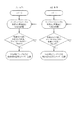
次に、本発明にかかわる各本体101と102に対応した寿命判断を図4を用いて説明する。
Next, the life judgment corresponding to each of the
本実施例では、本体101と本体102は、前述したように紙間の長さが異なっており、プロセス速度がそれぞれ異なるものである。従って、式(3)に準ずる寿命(交換時期)判断を行う必要がある。
(1)本体101でのプロセスカートリッジの寿命(交換時期)
本体101の枚数+本体102の枚数÷Max102×Max101
>Max101・・・(4)
(2)本体102でのプロセスカートリッジの寿命(交換時期)
本体101の枚数÷Max101×Max102+本体102の枚数
>Max102・・・(5)
上式で、
Max101 :本体101で通紙できる最大の枚数 (枚数閾値)
Max102 :本体102で通紙できる最大の枚数 (枚数閾値)
式(1)で示すように、本体101は紙間が長く、式(2)で示すように、本体102は紙間が短い。この紙間の差から、感光体や現像ローラ等の走行距離の逆比から算出される寿命(交換時期)は、式(3)より1.33倍となる。そこで、本体101でのプロセスカートリッジの寿命(交換時期)が、例えば、9000枚の場合、本体101で寿命(交換時期)は
本体102の枚数閾値=9000枚×1.33=12000枚・・・・(6)となる。
In this embodiment, the
(1) Life of process cartridge in main body 101 (replacement time)
Number of
> Max101 ... (4)
(2) Life of process cartridge in main body 102 (replacement time)
Number of
In the above formula,
Max101: the maximum number of sheets that can be passed through the main body 101 (threshold number of sheets)
Max102: the maximum number of sheets that can be passed through the main body 102 (number threshold)
As shown by the equation (1), the
従って
Max101:本体101で通紙できる最大の枚数(枚数閾値)=9000枚
Max102:本体102で通紙できる最大の枚数(枚数閾値)=12000枚となる。
Therefore, Max101: the maximum number of sheets that can be passed by the main body 101 (number threshold) = 9000 sheets Max102: the maximum number of sheets that can be passed by the main body 102 (number threshold) = 12000 sheets
以上より、式(4)、式(5)は、
(1)本体101でのプロセスカートリッジの寿命(交換時期)
本体101の枚数+本体102の枚数÷12000×9000
>9000(枚)・・・(7)
(2)本体102でのプロセスカートリッジの寿命(交換時期)
本体101の枚数÷9000×12000+本体102の枚数
>12000(枚)・・・(8)となる。
From the above, equations (4) and (5) are
(1) Life of process cartridge in main body 101 (replacement time)
Number of
> 9000 (sheets) (7)
(2) Life of process cartridge in main body 102 (replacement time)
The number of the
式(7)は本体101での寿命算出式である。また、式(8)は本体102での寿命算出式である。本発明では、これらの式を本体毎に使い分けることで、どちらの本体にいれても、正確に寿命を換算し求めることができる。
Equation (7) is an equation for calculating the life of the
式(7)は、カートリッジが本体101に装着されている場合の式であり、自身の本体101での記録枚数に、自身以外の本体102での記録枚数を本体101で通紙できる最大枚数(枚数閾値)9000枚と本体102で通紙できる最大枚数(枚数閾値)12000枚との比を用いて換算することによって正確に使用量を求めている。
Equation (7) is an equation in the case where the cartridge is mounted on the
式(8)は、カートリッジが本体102に装着されている場合の式であり、自身の本体102での記録枚数に、自身以外の本体101での記録枚数を本体101で通紙できる最大枚数(枚数閾値)9000枚と本体102で通紙できる最大枚数(枚数閾値)12000枚との比を用いて換算することによって正確に使用量を求めている。
Equation (8) is an equation in the case where the cartridge is mounted on the
例えば、交互にカートリッジを本体101と102に装着した場合として、プロセスカートリッジを本体102に入れて、次に本体101に入れたとする。
For example, assuming that the cartridges are alternately mounted on the
プロセスカートリッジが本体102に装着されたとき、本体102における通紙記録枚数は、図3に示す本体102用の使用量情報記憶領域21に記憶する。次に、このプロセスカートリッジを本体101に装着すると、本体101の通紙記録枚数は、図3に示す本体101用の使用量情報記憶領域ア11に記憶する。
(3) When the process cartridge is mounted on the
このまま、本体101で寿命(交換時期)を迎える場合は、式(7)に従い、本体102の通紙記録枚数をカートリッジCの記憶素子Mの記憶領域21から読み出し、通紙記録枚数の閾値の比9000/12000を用いて本体101相当の枚数に換算し、その値に本体101の通紙記録枚数を加算する。この合計枚数が、本体101での枚数閾値の9000枚を越えると、図3の、本体101のCUP14が判断し、寿命切れランプ15を点灯させるとともに、カートリッジメモリ中の寿命切れ信号情報記憶領域15に、寿命がきれたことを示す履歴情報を記憶させる。
If the life (replacement time) of the
図4の本体101のフローチャートは本体101にカートリッジが装着された状態における寿命判定のフロー図(式(7)に従う場合)であり、本体102のフォローチャートは本体102にカートリッジが装着された状態における寿命(交換時期)判定のフロー図(式(8)に従う場合)である。
The flowchart of the
なお、プロセスカートリッジが常に、本体101に装着されていた場合は、図4において、本体102の枚数が0枚となるので、閾値のMax101=9000枚で寿命(交換時期)となる。
In the case where the process cartridge is always mounted on the
また、プロセスカートリッジが常に、本体102に装着されていた場合は、図4において、本体101の枚数が0枚となるので、閾値のMax102=12000枚で寿命(交換時期)となる。
(4) In the case where the process cartridge is always mounted on the
本実施例2は、帯電方式をACバイアス方式からDCバイアス方式にして、感光体の寿命を延ばした別本体103に関するものであり、図5を用いて説明をする。
Second Embodiment The second embodiment relates to another
図5は画像形成装置本体101と103の違いを説明するために本体を模式的に示した図である。
FIG. 5 is a diagram schematically showing a main body of the
図5において、本体101は、実施例1の101と同じ本体であり、帯電ローラにACバイアスを印加している。一方、本体103は、帯電ローラにDCバイアスを印加している。
In FIG. 5, the
本体101の1次帯電ローラ2は、感光ドラム1に従動当接して帯電を行うAC接触帯電方式の帯電装置を構成し、2000Vpp、1000Hzの交流電圧成分と−600vのDC電圧成分を重畳したバイアスを印加した1次帯電ローラ2により感光ドラム1の表面は−600vに帯電される。
The primary charging roller 2 of the
本体103の1次帯電ローラ2は、感光ドラム1に従動当接して帯電を行うDC接触帯電方式の帯電装置を構成し、−1100vのDC電圧が印加した1次帯電ローラ2により感光ドラム1の表面は−600vに帯電される。なお、本実施の形態において、感光ドラム1は直径30mmの負帯電OPC感光体であり、その周速度は90mm/secである。
The primary charging roller 2 of the
本体101のAC帯電方式は、本体103のDC帯電方式と比較して、放電量が多い。放電を受けた量に比例して、表面が劣化を早める。つまり、本体101のほうが、本体103より、感光ドラムが摩耗しやすくなる。
(4) The AC charging method of the
そこで、同一のプロセスカートリッジをそれぞれの本体に装着した場合、プロセスカートリッジとしての寿命(交換時期)が異なってしまう。そこで、実施例1と同様に、プロセスカートリッジのメモリを用いて、それぞれの本体に応じて、寿命(交換時期)をコントロールする。 Therefore, when the same process cartridge is mounted on each main body, the life (replacement time) of the process cartridge differs. Therefore, similarly to the first embodiment, the life (replacement time) is controlled according to each main body using the memory of the process cartridge.
以下、本発明にかかわる各本体101と103に対応した寿命(交換時期)判断を説明する。
Hereinafter, the life (replacement time) judgment corresponding to each of the
本実施例では、本体101と本体103は、前述したように転写部の摺擦により感光ドラムの寿命(交換時期)が異なる。従って、以下の式で寿命(交換時期)判断する。
(1)本体101でのプロセスカートリッジの寿命(交換時期)
本体101の枚数+本体103の枚数÷Max103×Max101
>Max101・・・(9)
(2)本体103でのプロセスカートリッジの寿命(交換時期)
本体101の枚数÷Max101×Max103+本体103の枚数
>Max103 ・・・(10)
上式で、
Max101:本体101で通紙できる最大の枚数(枚数閾値)
Max103:本体103で通紙できる最大の枚数(枚数閾値)
例えば、Max101として本体101で通紙できる枚数閾値が9000枚である。一方、本体103の通紙できる寿命が、感光ドラムの摩耗を減らして、14000枚になった。そこで、Max103として、14000枚とすれば、実施例1と同様に、それぞれの本体で、適正な寿命(交換時期)を判定できる。
In this embodiment, the life (replacement time) of the photosensitive drum differs between the
(1) Life of process cartridge in main body 101 (replacement time)
Number of
> Max101 ... (9)
(2) Life of process cartridge in main body 103 (replacement time)
Number of
In the above formula,
Max101: the maximum number of sheets that can be passed through the main body 101 (threshold number of sheets)
Max103: the maximum number of sheets that can be passed by the main body 103 (number threshold)
For example, the threshold value for the number of sheets that can be passed through the
本実施例3は、感光ドラムと転写材Pの摺擦圧を減らして、感光体の寿命を延ばした別本体104に関するものであり、図6を用いて説明をする。 Third Embodiment The third embodiment relates to a separate main body 104 in which the life of the photosensitive member is extended by reducing the sliding friction pressure between the photosensitive drum and the transfer material P, and will be described with reference to FIG.
図6は画像形成装置本体101と104の違いを説明するために本体を模式的に示した図である。
FIG. 6 is a diagram schematically showing a main body of the
図6において、本体101は、実施例1の101と同じ本体であり、転写部材としての転写ローラ5とを備え、転写ベルト10で転写材Pを搬送し、トナー画像を転写ローラ5で転写ベルト10を介して転写する。一方、本体104は、転写部材としての転写コロナ18を備えている。
In FIG. 6, a
転写ローラ5は転写ベルト10を介し感光ドラム1に対し、総圧1kgで加圧している。一方、転写コロナ18は非接触であり、転写ベルト10は軽く感光ドラム1と接触している。
(4) The transfer roller 5 presses the
転写ベルト10は通紙時には、転写材Pを介して感光ドラム1に当接している。本体101は当接圧が本体104より高いため、感光体1が転写材Pや転写ベルト10と摺擦しやすく、感光体1が摩耗しやすい。
The
本体101と本体104は、転写部での摺擦により感光ドラム1の寿命に差がでる。そこで、同一のプロセスカートリッジをそれぞれの本体に装着した場合、プロセスカートリッジとしての寿命(交換時期)が異なってしまう。そこで、実施例1と同様に、プロセスカートリッジのメモリを用いて、それぞれの本体に応じて、寿命(交換時期)をコントロールする。
(4) The life of the
以下、本発明にかかわる各本体101と104に対応した寿命(交換時期)判断を説明する。
Hereinafter, the life (replacement time) judgment corresponding to each of the
本実施例では、本体101と本体104は、前述したように転写部の摺擦により感光ドラムの寿命(交換時期)が異なる。従って、以下の式で寿命(交換時期)判断する。
(1)本体101でのプロセスカートリッジの寿命(交換時期)
本体101の枚数+本体104の枚数÷Max104×Max101
>Max101・・・(9)
(2)本体103でのプロセスカートリッジの寿命(交換時期)
本体101の枚数÷Max101×Max104+本体104の枚数
>Max104・・(10)
上式で、
Max101:本体101で通紙できる最大の枚数(枚数閾値)
Max104:本体104で通紙できる最大の枚数(枚数閾値)
例えば、Max101として本体101で通紙できる枚数閾値が9000枚である。一方、本体104の通紙できる寿命が、感光ドラムの摩耗を減らして、10000枚になった。そこで、Max104として、10000枚とすれば、実施例1と同様に、それぞれの本体で、適正な寿命(交換時期)を判定できる。
In the present embodiment, the
(1) Life of process cartridge in main body 101 (replacement time)
Number of
> Max101 ... (9)
(2) Life of process cartridge in main body 103 (replacement time)
The number of main bodies 101101Max101 × Max104 + the number of main bodies 104> Max104 (10)
In the above formula,
Max101: the maximum number of sheets that can be passed through the main body 101 (threshold number of sheets)
Max 104: the maximum number of sheets that can be passed through the main body 104 (number threshold)
For example, the threshold value for the number of sheets that can be passed through the
なお、上記実施例1〜3においては、2種類の画像形成装置の夫々に装着可能なプロセスカートリッジについて説明したが、3種類以上の画像形成装置に装着可能なプロセスカ
また、上記実施例1〜3においては、カートリッジの寿命(交換時期)を判定するための通紙記録枚数をカートリッジのメモリに記憶させることを例にあげて説明したが、カートリッジの寿命(交換時期)を判定するための使用量に関する情報であれば、通紙記録枚数以外の情報を用いてもよい。
In the first to third embodiments, a process cartridge that can be mounted on each of two types of image forming apparatuses has been described. However, a process cartridge that can be mounted on three or more types of image forming apparatuses. In the third embodiment, the example in which the number of sheets passed for determining the life (replacement time) of the cartridge is stored in the memory of the cartridge has been described. As long as the information is related to the amount, information other than the number of recorded sheets may be used.
また、カラー画像形成装置を例に説明したが、本発明をモノクロ画像形成装置に適用することも可能である。 Also, while the color image forming apparatus has been described as an example, the present invention can be applied to a monochrome image forming apparatus.
また、上記実施例では、カートリッジとして、像担持体である感光ドラムと、1次帯電ローラと、クリーニング手段と、クリーニング容器と、現像器と、記憶部とを有するカートリッジを例として説明したが、カートリッジの構成としてはこれに限らず、例えば、少なくとも現像器と記憶部とを有するカートリッジにも適用可能である。 In the above embodiment, the cartridge has been described as an example of a cartridge having a photosensitive drum as an image carrier, a primary charging roller, a cleaning unit, a cleaning container, a developing device, and a storage unit. The configuration of the cartridge is not limited to this, and is applicable to, for example, a cartridge having at least a developing unit and a storage unit.
以上の実施例で説明したように、互換性のあるカートリッジが、それぞれ仕様の異なる本体に挿入されたときに、その本体での使用量情報をカートリッジに設けられた記憶媒体に記憶して、それぞれ使用の異なる本体に装着されて使用されても正確にカートリッジの寿命(交換時期)を把握することができる。 As described in the above embodiments, when the compatible cartridges are inserted into the main bodies having different specifications, the usage information in the main bodies is stored in the storage medium provided in the cartridge, and It is possible to accurately grasp the life of the cartridge (replacement time) even when the cartridge is used by being attached to a main body used differently.
また、互換性のあるカートリッジが、それぞれ仕様の異なる本体に挿入されたときの各々の使用量情報をカートリッジに設けられた記憶媒体に記憶し、カートリッジが装着されている本体自身の使用量と自身以外の使用量とからカートリッジの寿命(交換時期)を正確に判断することが可能となる。 In addition, when a compatible cartridge is inserted into a main unit having a different specification, the usage information is stored in a storage medium provided in the cartridge. It is possible to accurately determine the life (replacement time) of the cartridge from the usage amount other than the above.
また、それぞれ異なる本体に対する寿命の上限に対応する閾値もカートリッジの記憶媒体に記憶し、互換性のあるプロセスカートリッジにおいて、異なる種類の本体に対しても、その本体に対応した寿命(交換時期)を正確に判断することができる。 In addition, the threshold values corresponding to the upper limits of the lifespans of the different main bodies are also stored in the storage medium of the cartridge, and the lifespan (replacement time) corresponding to the main bodies of different types in the compatible process cartridges is also stored. It can be determined accurately.
また、カートリッジが寿命(交換時期)であることを示す履歴情報もカートリッジの記憶媒体に記憶して、カートリッジが装着されたときに、即座に寿命(交換時期)判定を行うことができる。 Also, history information indicating that the life of the cartridge (replacement time) is stored in the storage medium of the cartridge, and the life (replacement time) can be immediately determined when the cartridge is mounted.
1 感光ドラム
2 1次帯電ローラ
3 クリーニング手段
4 クリーニング容器
5 転写ローラ
6 現像器
9 テンションローラ
10 転写ベルト
71,72,73,74 カートリッジメモリ
81,82,83,84 プロセスカートリッジ
111,112,113,114 装着部
101,102 画像形成本体
P 転写材
Claims (24)
前記記憶部に記憶された情報に応じて前記カートリッジの交換時期を判断する制御部とを有し、
前記記憶部は前記装置の各仕様での使用量に関する情報を各々記憶する記憶領域を有し、
前記制御部は、前記記憶部の記憶領域に記憶された前記各仕様での使用量情報に応じて前記カートリッジの交換時期を判断することを特徴とする画像形成装置。 At least a part of members necessary for image formation and a storage unit, a mounting unit to which a detachable cartridge is mounted for an image forming apparatus having different specifications,
A control unit that determines a replacement time of the cartridge according to the information stored in the storage unit,
The storage unit has a storage area for storing information on the usage amount in each specification of the device,
The image forming apparatus according to claim 1, wherein the control unit determines a replacement time of the cartridge in accordance with usage amount information in each specification stored in a storage area of the storage unit.
前記制御部は、前記カートリッジの交換時期を判断するための情報と前記閾値に関する情報とを比較して、カートリッジが交換時期に到達したか否かを判断することを特徴とする請求項2に記載の画像形成装置。 The storage unit further includes a storage area for storing information on a threshold corresponding to the upper limit of the usage amount in each specification,
3. The control unit according to claim 2, wherein the control unit compares information for determining a replacement time of the cartridge with information on the threshold to determine whether the cartridge has reached a replacement time. 4. Image forming apparatus.
前記制御部は、前記カートリッジが交換時期に到達したと判断した場合に、前記履歴情報を記憶する記憶領域にカートリッジが交換時期であることを示す履歴情報を書き込むことを特徴とする請求項3に記載の画像形成装置。 The storage unit further includes a storage area for storing history information indicating that the cartridge has reached a replacement time,
4. The control unit according to claim 3, wherein, when determining that the cartridge has reached a replacement time, the control unit writes history information indicating that the cartridge is to be replaced in a storage area for storing the history information. The image forming apparatus as described in the above.
前記記憶部は、各仕様での使用量に関する情報を各々記憶する記憶領域を有することを特徴とするカートリッジ。 Attachment section of an image forming apparatus having different specifications having at least a part of members necessary for image formation and a storage section, and having a control section for judging replacement time of the cartridge in accordance with information stored in the storage section. A removable cartridge,
The cartridge according to claim 1, wherein the storage unit includes a storage area for storing information on a usage amount in each specification.
前記記憶媒体には、各仕様での使用量に関する情報を各々記憶する記憶領域を有することを特徴とする記憶媒体。 A storage medium having at least a part of a member necessary for image formation and a storage unit, and being mounted on a cartridge detachable from a mounting unit of an image forming apparatus having different specifications,
The storage medium according to claim 1, wherein the storage medium has a storage area for storing information on a usage amount in each specification.
Priority Applications (6)
| Application Number | Priority Date | Filing Date | Title |
|---|---|---|---|
| JP2003302521A JP4298434B2 (en) | 2002-08-30 | 2003-08-27 | Image forming apparatus |
| DE60334763T DE60334763D1 (en) | 2002-08-30 | 2003-08-28 | Image generation system with cartridge |
| US10/649,835 US6954596B2 (en) | 2002-08-30 | 2003-08-28 | Storage area storing information of the amount of use of each feature of different image forming apparatuses, a cartridge having such a storage area, and an image forming apparatus mounting such a cartridge |
| EP03019489A EP1394633B1 (en) | 2002-08-30 | 2003-08-28 | System for forming an image with cartridge |
| CNB03157923XA CN1288510C (en) | 2002-08-30 | 2003-08-29 | Image forming device, cassette module and storage medium |
| KR1020030060079A KR100555001B1 (en) | 2002-08-30 | 2003-08-29 | Image forming apparatus, cartridge and storage medium |
Applications Claiming Priority (2)
| Application Number | Priority Date | Filing Date | Title |
|---|---|---|---|
| JP2002253899 | 2002-08-30 | ||
| JP2003302521A JP4298434B2 (en) | 2002-08-30 | 2003-08-27 | Image forming apparatus |
Publications (3)
| Publication Number | Publication Date |
|---|---|
| JP2004110012A true JP2004110012A (en) | 2004-04-08 |
| JP2004110012A5 JP2004110012A5 (en) | 2006-10-12 |
| JP4298434B2 JP4298434B2 (en) | 2009-07-22 |
Family
ID=31497701
Family Applications (1)
| Application Number | Title | Priority Date | Filing Date |
|---|---|---|---|
| JP2003302521A Expired - Fee Related JP4298434B2 (en) | 2002-08-30 | 2003-08-27 | Image forming apparatus |
Country Status (6)
| Country | Link |
|---|---|
| US (1) | US6954596B2 (en) |
| EP (1) | EP1394633B1 (en) |
| JP (1) | JP4298434B2 (en) |
| KR (1) | KR100555001B1 (en) |
| CN (1) | CN1288510C (en) |
| DE (1) | DE60334763D1 (en) |
Cited By (3)
| Publication number | Priority date | Publication date | Assignee | Title |
|---|---|---|---|---|
| JP2013054184A (en) * | 2011-09-02 | 2013-03-21 | Brother Ind Ltd | Image forming apparatus, and program |
| JP2017227736A (en) * | 2016-06-22 | 2017-12-28 | コニカミノルタ株式会社 | Image forming apparatus |
| WO2021153553A1 (en) * | 2020-01-29 | 2021-08-05 | Brother Kogyo Kabushiki Kaisha | Image forming apparatus, image forming system, method for controlling image forming apparatus, and non-transitory storage medium storing a set of program instructions installed on and executed by computer for controlling image forming apparatus |
Families Citing this family (11)
| Publication number | Priority date | Publication date | Assignee | Title |
|---|---|---|---|---|
| JP4108065B2 (en) * | 2004-06-16 | 2008-06-25 | シャープ株式会社 | Image forming apparatus |
| KR100823253B1 (en) * | 2004-09-02 | 2008-04-17 | 삼성전자주식회사 | Image forming apparatus and storage unit of the image forming apparatus |
| CN1746783B (en) * | 2004-09-10 | 2012-03-28 | 佳能株式会社 | Image forming device and cartridge |
| JP4810205B2 (en) * | 2005-11-30 | 2011-11-09 | 株式会社リコー | Image forming apparatus and image forming system |
| JP2007171799A (en) * | 2005-12-26 | 2007-07-05 | Fuji Xerox Co Ltd | Image forming apparatus, image forming unit, method of replacing image forming unit, and method for manufacturing image forming unit |
| KR100863252B1 (en) | 2008-02-29 | 2008-10-15 | 삼성전자주식회사 | Developer and its memory unit and image forming apparatus |
| JP4676523B2 (en) * | 2008-09-17 | 2011-04-27 | シャープ株式会社 | Image forming apparatus |
| JP6685756B2 (en) * | 2016-02-17 | 2020-04-22 | キヤノン株式会社 | Image forming apparatus, control method thereof, and program |
| JP6965513B2 (en) * | 2016-12-15 | 2021-11-10 | コニカミノルタ株式会社 | Image forming device, program, and image forming system |
| JP7106295B2 (en) * | 2018-02-28 | 2022-07-26 | キヤノン株式会社 | image forming device |
| CN115729073A (en) * | 2022-11-21 | 2023-03-03 | 珠海奔图电子有限公司 | Detection device, conductive member, process cartridge, process cartridge set, image forming device |
Family Cites Families (9)
| Publication number | Priority date | Publication date | Assignee | Title |
|---|---|---|---|---|
| US5184178A (en) * | 1988-09-13 | 1993-02-02 | Canon Kabushiki Kaisha | Image recording apparatus having an interchangeable cartridge |
| US4961088A (en) | 1989-04-20 | 1990-10-02 | Xerox Corporation | Monitor/warranty system for electrostatographic reproducing machines using replaceable cartridges |
| JP2897494B2 (en) | 1991-10-04 | 1999-05-31 | キヤノン株式会社 | Process cartridge |
| JP3270121B2 (en) | 1992-06-30 | 2002-04-02 | キヤノン株式会社 | Image forming device |
| US6128448A (en) | 1998-12-03 | 2000-10-03 | Hewlett-Packard Company | Method and apparatus for toner level monitoring and motion sensing |
| JP2001175133A (en) | 1999-12-15 | 2001-06-29 | Canon Inc | System for notifying remaining amount of developer and usage of other consumables and image forming apparatus |
| JP2001215862A (en) | 2000-01-28 | 2001-08-10 | Canon Inc | Image forming apparatus and cartridge detachable from this image forming apparatus |
| US7082660B2 (en) | 2001-08-24 | 2006-08-01 | Canon Kabushiki Kaisha | Recycling method and image forming apparatus manufactured using recycling method |
| US6792216B2 (en) * | 2002-12-19 | 2004-09-14 | Hewlett-Packard Development Company, L.P. | System for estimating the remaining life of a print cartridge |
-
2003
- 2003-08-27 JP JP2003302521A patent/JP4298434B2/en not_active Expired - Fee Related
- 2003-08-28 US US10/649,835 patent/US6954596B2/en not_active Expired - Fee Related
- 2003-08-28 EP EP03019489A patent/EP1394633B1/en not_active Expired - Lifetime
- 2003-08-28 DE DE60334763T patent/DE60334763D1/en not_active Expired - Lifetime
- 2003-08-29 CN CNB03157923XA patent/CN1288510C/en not_active Expired - Fee Related
- 2003-08-29 KR KR1020030060079A patent/KR100555001B1/en not_active Expired - Fee Related
Cited By (7)
| Publication number | Priority date | Publication date | Assignee | Title |
|---|---|---|---|---|
| JP2013054184A (en) * | 2011-09-02 | 2013-03-21 | Brother Ind Ltd | Image forming apparatus, and program |
| JP2017227736A (en) * | 2016-06-22 | 2017-12-28 | コニカミノルタ株式会社 | Image forming apparatus |
| WO2021153553A1 (en) * | 2020-01-29 | 2021-08-05 | Brother Kogyo Kabushiki Kaisha | Image forming apparatus, image forming system, method for controlling image forming apparatus, and non-transitory storage medium storing a set of program instructions installed on and executed by computer for controlling image forming apparatus |
| JP2021117468A (en) * | 2020-01-29 | 2021-08-10 | ブラザー工業株式会社 | Image forming apparatus, image forming system, control method and program of image forming apparatus |
| US11378913B2 (en) | 2020-01-29 | 2022-07-05 | Brother Kogyo Kabushiki Kaisha | Image forming apparatus capable of controlling extension of use of drum cartridge |
| JP7413799B2 (en) | 2020-01-29 | 2024-01-16 | ブラザー工業株式会社 | Image forming apparatus, image forming system, control method and program for image forming apparatus |
| US11934144B2 (en) | 2020-01-29 | 2024-03-19 | Brother Kogyo Kabushiki Kaisha | Image forming apparatus capable of controlling extension of use of drum cartridge |
Also Published As
| Publication number | Publication date |
|---|---|
| JP4298434B2 (en) | 2009-07-22 |
| EP1394633B1 (en) | 2010-11-03 |
| KR20040021537A (en) | 2004-03-10 |
| US6954596B2 (en) | 2005-10-11 |
| EP1394633A1 (en) | 2004-03-03 |
| CN1288510C (en) | 2006-12-06 |
| DE60334763D1 (en) | 2010-12-16 |
| US20040091274A1 (en) | 2004-05-13 |
| CN1492287A (en) | 2004-04-28 |
| KR100555001B1 (en) | 2006-02-24 |
Similar Documents
| Publication | Publication Date | Title |
|---|---|---|
| JP4706682B2 (en) | Double printing system | |
| JP4298434B2 (en) | Image forming apparatus | |
| JP6919246B2 (en) | Image forming device and control program of image forming device | |
| JP5426624B2 (en) | Image forming apparatus | |
| JP5273596B2 (en) | Image forming apparatus | |
| JP3313978B2 (en) | Process cartridge and electrophotographic image forming apparatus | |
| US20100303482A1 (en) | Toner cartridge and control method of displaying the residual toner quantity in the same toner cartridge | |
| JP6554775B2 (en) | Image forming apparatus | |
| KR20060056242A (en) | Image forming apparatus and process cartridge | |
| JP2004294761A (en) | Apparatus and method for calculating toner consumption and image forming apparatus | |
| US10254697B2 (en) | Image forming apparatus | |
| JP4269017B2 (en) | Image forming apparatus, consumables used therefor, and method for determining the consumables | |
| JPH0451259A (en) | Image forming cartridge replacing method | |
| JP2019086594A (en) | Image forming device | |
| JP2006227325A (en) | Image forming apparatus | |
| JP2003195699A (en) | Image forming device | |
| JP4948100B2 (en) | Toner consumption prediction amount calculation method, toner consumption prediction amount calculation device, and image forming apparatus | |
| JP2012108483A (en) | Image forming apparatus | |
| JPH1039691A (en) | Photoconductor life detecting method, image forming apparatus, and process cartridge | |
| JP2006259539A (en) | Toner level display method | |
| JP2008058726A (en) | Image forming apparatus | |
| JP6563834B2 (en) | Image forming apparatus and error notification method | |
| JP2006084684A (en) | Image forming apparatus | |
| JP2008158246A (en) | Image forming apparatus | |
| JP2007156255A (en) | Image forming apparatus |
Legal Events
| Date | Code | Title | Description |
|---|---|---|---|
| A521 | Request for written amendment filed |
Free format text: JAPANESE INTERMEDIATE CODE: A523 Effective date: 20060825 |
|
| A621 | Written request for application examination |
Free format text: JAPANESE INTERMEDIATE CODE: A621 Effective date: 20060825 |
|
| A977 | Report on retrieval |
Free format text: JAPANESE INTERMEDIATE CODE: A971007 Effective date: 20080916 |
|
| A131 | Notification of reasons for refusal |
Free format text: JAPANESE INTERMEDIATE CODE: A131 Effective date: 20081111 |
|
| A521 | Request for written amendment filed |
Free format text: JAPANESE INTERMEDIATE CODE: A523 Effective date: 20090107 |
|
| TRDD | Decision of grant or rejection written | ||
| A01 | Written decision to grant a patent or to grant a registration (utility model) |
Free format text: JAPANESE INTERMEDIATE CODE: A01 Effective date: 20090331 |
|
| A01 | Written decision to grant a patent or to grant a registration (utility model) |
Free format text: JAPANESE INTERMEDIATE CODE: A01 |
|
| A61 | First payment of annual fees (during grant procedure) |
Free format text: JAPANESE INTERMEDIATE CODE: A61 Effective date: 20090415 |
|
| R150 | Certificate of patent or registration of utility model |
Free format text: JAPANESE INTERMEDIATE CODE: R150 |
|
| FPAY | Renewal fee payment (event date is renewal date of database) |
Free format text: PAYMENT UNTIL: 20120424 Year of fee payment: 3 |
|
| FPAY | Renewal fee payment (event date is renewal date of database) |
Free format text: PAYMENT UNTIL: 20130424 Year of fee payment: 4 |
|
| FPAY | Renewal fee payment (event date is renewal date of database) |
Free format text: PAYMENT UNTIL: 20130424 Year of fee payment: 4 |
|
| FPAY | Renewal fee payment (event date is renewal date of database) |
Free format text: PAYMENT UNTIL: 20140424 Year of fee payment: 5 |
|
| LAPS | Cancellation because of no payment of annual fees |