JP2004110011A - Image forming device and method for controlling image forming device - Google Patents
Image forming device and method for controlling image forming device Download PDFInfo
- Publication number
- JP2004110011A JP2004110011A JP2003302020A JP2003302020A JP2004110011A JP 2004110011 A JP2004110011 A JP 2004110011A JP 2003302020 A JP2003302020 A JP 2003302020A JP 2003302020 A JP2003302020 A JP 2003302020A JP 2004110011 A JP2004110011 A JP 2004110011A
- Authority
- JP
- Japan
- Prior art keywords
- image
- developer
- carrier
- image forming
- forming apparatus
- Prior art date
- Legal status (The legal status is an assumption and is not a legal conclusion. Google has not performed a legal analysis and makes no representation as to the accuracy of the status listed.)
- Pending
Links
Images


Classifications
-
- G—PHYSICS
- G03—PHOTOGRAPHY; CINEMATOGRAPHY; ANALOGOUS TECHNIQUES USING WAVES OTHER THAN OPTICAL WAVES; ELECTROGRAPHY; HOLOGRAPHY
- G03G—ELECTROGRAPHY; ELECTROPHOTOGRAPHY; MAGNETOGRAPHY
- G03G15/00—Apparatus for electrographic processes using a charge pattern
- G03G15/06—Apparatus for electrographic processes using a charge pattern for developing
- G03G15/08—Apparatus for electrographic processes using a charge pattern for developing using a solid developer, e.g. powder developer
- G03G15/0822—Arrangements for preparing, mixing, supplying or dispensing developer
- G03G15/0848—Arrangements for testing or measuring developer properties or quality, e.g. charge, size, flowability
- G03G15/0856—Detection or control means for the developer level
- G03G15/0862—Detection or control means for the developer level the level being measured by optical means
-
- G—PHYSICS
- G03—PHOTOGRAPHY; CINEMATOGRAPHY; ANALOGOUS TECHNIQUES USING WAVES OTHER THAN OPTICAL WAVES; ELECTROGRAPHY; HOLOGRAPHY
- G03G—ELECTROGRAPHY; ELECTROPHOTOGRAPHY; MAGNETOGRAPHY
- G03G15/00—Apparatus for electrographic processes using a charge pattern
- G03G15/06—Apparatus for electrographic processes using a charge pattern for developing
- G03G15/08—Apparatus for electrographic processes using a charge pattern for developing using a solid developer, e.g. powder developer
- G03G15/0822—Arrangements for preparing, mixing, supplying or dispensing developer
- G03G15/0863—Arrangements for preparing, mixing, supplying or dispensing developer provided with identifying means or means for storing process- or use parameters, e.g. an electronic memory
-
- G—PHYSICS
- G03—PHOTOGRAPHY; CINEMATOGRAPHY; ANALOGOUS TECHNIQUES USING WAVES OTHER THAN OPTICAL WAVES; ELECTROGRAPHY; HOLOGRAPHY
- G03G—ELECTROGRAPHY; ELECTROPHOTOGRAPHY; MAGNETOGRAPHY
- G03G2215/00—Apparatus for electrophotographic processes
- G03G2215/01—Apparatus for electrophotographic processes for producing multicoloured copies
- G03G2215/0167—Apparatus for electrophotographic processes for producing multicoloured copies single electrographic recording member
- G03G2215/0174—Apparatus for electrophotographic processes for producing multicoloured copies single electrographic recording member plural rotations of recording member to produce multicoloured copy
- G03G2215/0177—Rotating set of developing units
Abstract
Description
本発明は、電子写真方式、静電記録方式等を用い、現像剤担持体による接触現像方式にて現像動作を行う現像手段を有する画像形成装置及び該画像形成装置の制御方法に関するものである。 The present invention relates to an image forming apparatus having a developing unit that performs a developing operation by a contact developing method using a developer carrier using an electrophotographic method, an electrostatic recording method, or the like, and a method for controlling the image forming apparatus.
従来、記録媒体上に画像を形成する機能を備えた、例えば、複写機、プリンタ、あるいは、ファクシミリ装置等の画像形成装置においては、感光ドラム等の像担持体上に形成した静電潜像を、現像剤を用いて現像手段により現像剤像(トナー像)として可視化する。 Conventionally, with a function of forming an image on a recording medium, for example, in an image forming apparatus such as a copying machine, a printer, or a facsimile machine, an electrostatic latent image formed on an image carrier such as a photosensitive drum is used. Then, it is visualized as a developer image (toner image) by a developing means using a developer.
このような現像手段として、例えば、乾式一成分接触現像方式が提案され実用化されている。この場合多くは、回転する像担持体(感光ドラム)と同じく回転する、現像剤を担持した現像ローラ等の現像剤担持体を、適当な相対周速差で押圧もしくは接触させることで、静電潜像を現像している。加えて、この場合は磁性材料が不要であり、装置の簡略化及び小型化が容易である、非磁性トナーを含む一成分現像剤を使用することでフルカラー画像形成装置に応用が可能である等、多くの利点を有している。 乾 As such a developing means, for example, a dry single-component contact developing method has been proposed and put to practical use. In this case, in many cases, a developer carrier such as a developing roller carrying a developer, which rotates in the same manner as a rotating image carrier (photosensitive drum), is pressed or brought into contact with an appropriate relative peripheral speed difference, so that electrostatic force is applied. The latent image is being developed. In addition, in this case, a magnetic material is not required, and the apparatus can be easily simplified and downsized, and can be applied to a full-color image forming apparatus by using a one-component developer containing a non-magnetic toner. Has many advantages.
近年、需要の多様化の中にあって、例えばオフィス等で使用されるプリンタにより出力される画像のカラー化に対する要望が増加している。 In recent years, with the diversification of demand, there has been an increasing demand for colorization of images output by printers used in offices and the like.
これに応えるべく、いくつかの手法によるカラー画像形成装置が提案されているが、その一例として、表面にトナー像が形成される感光ドラム等の第一の像担持体以外に、第一の像担持体より複数色のトナー像が重ねて一次転写される第二の像担持体としての中間転写体を有し、中間転写体上に形成された各色の複合トナー像を一括して転写材に二次転写することで、色ずれのないカラー画像を得ることを目的とした、中間転写体方式のカラー画像形成装置が提案されている。 In order to respond to this, a color image forming apparatus using several techniques has been proposed. For example, in addition to a first image carrier such as a photosensitive drum on which a toner image is formed on a surface, a first image forming apparatus is provided. The image forming apparatus has an intermediate transfer body as a second image carrier on which a plurality of color toner images are superimposed and primary-transferred from the carrier, and collectively transfers a composite toner image of each color formed on the intermediate transfer body onto a transfer material. There has been proposed an intermediate transfer body type color image forming apparatus which aims at obtaining a color image without color shift by performing secondary transfer.
図12にその概略構成図を示すが、矢印の方向に所定のプロセススピードをもって回転駆動される感光ドラム101は、まず、その表面は帯電ローラ102によって、一様に帯電される。次に、画像情報に応じてON/OFF制御されたレーザビーム103による走査露光が施され、感光ドラム101上に静電潜像が形成される。
FIG. 12 shows a schematic configuration diagram of the
この静電潜像は、現像剤を収容した現像手段によって現像される。本例では、回転して各現像手段を切り替え可能な回転現像装置104により、現像、可視化される。
This electrostatic latent image is developed by developing means containing a developer. In this example, development and visualization are performed by the rotary developing
この回転現像装置104は、4つの各々の現像手段が現像剤担持体である現像ローラ111を有し、その4つの現像手段である、第1色目の現像剤(トナー)としてイエロートナーが収容された第1の現像器104a、第2色目のトナーとしてマゼンタトナーが収容された第2の現像器104b、第3色目のトナーとしてシアントナーが収容された第3の現像器104c、第4色目のトナーとしてブラックトナーが収容された第4の現像器104dを一体化した構成となっており、まず上記静電潜像は、第1色目のトナーとしてイエロートナーが収容された第1の現像器104aにより現像、可視化される。尚、これらのトナーは、一成分非磁性トナーであり、正規の極性は負極性である。
The rotary developing
可視化された第1のトナー像は、矢印の方向に回転駆動される中間転写体としての中間転写ベルト105と対向する第1の転写部位106において、中間転写ベルト105表面に静電転写(一次転写)される。尚、一次転写が終了した感光ドラム101表面に若干量残存する一次転写残留トナーは、クリーニング装置107により除去される。このクリーニング装置107は、感光ドラム101表面に対し、いわゆるカウンタ方向に当接する弾性部材を有するクリーニングブレード107aを有す。
The visualized first toner image is electrostatically transferred (primary transfer) to the surface of the
続いて上記工程を第2〜第4の現像手段104b〜104dを用いて、3回繰り返すことにより中間転写ベルト105上にトナー像が順次重ねて転写される。即ち、マゼンタトナーにより現像された第2のトナー像、シアントナーにより現像された第3のトナー像、ブラックトナーにより現像された第4のトナー像が順次中間転写ベルト105表面に転写、積層される。
{Circle over (3)} The above process is repeated three times using the second to fourth developing
その後、中間転写ベルト105表面に対して離間状態にあった二次転写ローラ108が中間転写ベルト105表面に圧接、回転駆動され、第2の転写部位109に所定のタイミングで搬送されてくる転写材P表面に、中間転写ベルト105表面に形成されたトナー像が一括転写(二次転写)され、この転写材Pは定着装置110へと搬送され、永久画像として定着された後、機外へと排出される。
Thereafter, the
ここでは、各現像手段104a、104b、104c、104dは、カートリッジの形態であり、現像剤担持体である現像ローラ111と、現像ローラ111に当接して、現像ローラ111上のトナー量を規制する規制部材としての現像ブレード112と、現像ローラ111に当接し、現像ローラ111に一成分非磁性トナーを供給する供給ローラ113と、供給ローラ113近傍にトナーを搬送する撹拌部材114と、を有し、画像形成装置内の現像装置104に対し着脱可能となっている。
Here, each of the developing
尚、現像ローラ111は、感光ドラム101に当接、回転することにより、現像手段内に収容されたトナーを担持して感光ドラム101表面の静電潜像部分に送り込む現像動作を行なう。そこで、所謂接触現像方式に適合すべく、少なくとも弾性体を有することが好ましい。そして、現像ローラ111にはトナーを現像ローラ111から感光ドラム101表面へ転移させるために、不図示の現像バイアス電源により所定の直流バイアスが供給される。
The developing
このように、現像剤担持体としては、弾性及び導電性を有する現像ローラを使用することが多い。即ち、現像ローラ111は、表面を像担持体に押圧もしくは接触させて現像を行うため、特に像担持体が剛体である場合、表面を傷つけることを避けるために、現像ローラ111を弾性体により構成するのである。
As described above, a developing roller having elasticity and conductivity is often used as the developer carrying member. That is, the developing
又、現像ブレード112は、金属薄板のバネ弾性を利用して、現像ローラ111表面に対し軽圧当接される。
The developing
しかしながら、このような一成分非磁性トナーを用いた画像形成装置にあっては、以下のような不具合が生じる場合があった。 However, in the image forming apparatus using such a one-component non-magnetic toner, the following problems may occur.
良好な画像品位を得るためには、トナーの帯電量は適正な大きさにある必要があり、これはトナー自身の帯電量と、現像ローラ111の回転に伴い、トナーが現像ローラ111と現像ブレード112との当接ニップ部に搬送され、そこでの摺擦による摩擦帯電により得られる帯電量から決定される。
In order to obtain good image quality, the charge amount of the toner needs to be at an appropriate level. This is because the charge amount of the toner itself and the rotation of the developing
そして、例えば長時間の放置状態を経た後に画像形成を行なうような場合にあっては、現像手段内のトナーは、トナー自身の帯電量が減衰している。よって、装置起動直後の初期段階においては、特にキャリアを用いない一成分非磁性トナーを使用する場合は、トナーに充分な電荷を付与されず帯電量が充分に得られていない、あるいは均一に保持することができない状態である。この状態で、画像形成が開始されてしまうと、画像濃度が低い、もしくは画像濃度が不均一であるといった画像不良が発生する場合がある。 {Circle around (2)} In the case where an image is formed after a long period of standing, for example, the charge amount of the toner in the developing unit is attenuated. Therefore, in the initial stage immediately after the start of the apparatus, particularly when using a one-component non-magnetic toner that does not use a carrier, sufficient charge is not applied to the toner and the charge amount is not sufficiently obtained, or the toner is not uniformly maintained. You cannot do that. If image formation is started in this state, an image defect such as low image density or uneven image density may occur.
特に、図12の画像形成装置にて採用されている所謂接触現像方式においては、現像ローラ111上で生じるトナーの帯電ムラが画像ムラとなって顕在化し易い。
Particularly, in the so-called contact developing method employed in the image forming apparatus of FIG. 12, uneven charging of the toner generated on the developing
又、この現象は、現像手段内に残存するトナー量が多い場合や、画像形成装置が設置されている周囲の環境が高温高湿環境下であるといったように、トナーの帯電量が得られにくい状況でより顕著に発生する傾向がある。 Also, this phenomenon is difficult to obtain the charge amount of the toner, such as when the amount of toner remaining in the developing unit is large, or when the surrounding environment where the image forming apparatus is installed is under a high temperature and high humidity environment. It tends to occur more noticeably in situations.
又、このような一成分非磁性トナーを用いた画像形成装置にあっては、未使用状態の現像手段を初めて使用し画像形成を行なう場合に、以下のような不具合が生じる場合があった。 In the image forming apparatus using such a one-component non-magnetic toner, the following problems may occur when an image is formed by using an unused developing unit for the first time.
一般的に未使用状態の現像手段は、トナーが収容されているトナー収容容器部と、現像ローラ、現像ブレード等の部材が配設されている現像部との間にシール部材が設けられており、ユーザがこのシール部材を除去することにより使用可能な状態となるが、使用初期にあっては、トナーが現像ローラ表面に均一にコーティングされにくく、この状態で画像形成を行なうと、画像濃度が不均一であるといった画像不良が発生する場合があった。 Generally, the developing means in an unused state is provided with a seal member between a toner storage container section in which toner is stored and a developing section in which members such as a developing roller and a developing blade are disposed. However, when the user removes the seal member, the seal member can be used. However, in the early stage of use, it is difficult for the toner to be uniformly coated on the surface of the developing roller. Image defects such as unevenness sometimes occurred.
又、良好な画像品位を得るためには、トナーの帯電量は適正な大きさにある必要があり、これはトナー自身の帯電量と、現像ローラの回転に伴い、トナーが現像ローラと現像ブレードとの当接ニップ部に搬送され、そこでの摺擦による摩擦帯電により得られる帯電量から決定される。 Also, in order to obtain good image quality, the charge amount of the toner needs to be of an appropriate size. This is because the charge amount of the toner itself and the rotation of the developing roller cause the toner to move to the developing roller and the developing blade. And is determined from the amount of charge obtained by frictional charging due to rubbing there.
しかし、未使用状態の現像手段を用いて画像形成を行なう場合にあっては、現像手段内のトナーは、トナー自身の帯電量が減衰しており、現像手段使用開始直後の初期段階においては、トナーに充分な電荷を付与されず帯電量が充分に得られていない、あるいは均一に保持することができない状態で画像形成が開始されてしまうことになる。このため画像濃度が低い、もしくは画像濃度が不均一であるといった画像不良が発生する場合があり、特に所謂接触現像方式にあっては、現像ローラ上でのトナーの帯電ムラが画像ムラとなって顕在化し易い。 However, when an image is formed using the developing unit in an unused state, the toner in the developing unit has an attenuated charge amount of the toner itself. Image formation is started in a state where sufficient charge is not provided to the toner and a sufficient charge amount is not obtained or the toner cannot be maintained uniformly. For this reason, image defects such as low image density or non-uniform image density may occur. Particularly, in a so-called contact developing method, uneven charging of toner on a developing roller causes image unevenness. Easy to manifest.
この現象は、その内部にマグネットを内包した現像スリーブと、磁性トナーとを用いた現像方式に比べ、磁力によるトナー搬送力がない現像手段においては、非常に発生し易く、特にその形状が略球形である一成分非磁性トナーを用いた一成分非磁性現像方式においては、より顕著である。 This phenomenon is very likely to occur in developing means that does not have a toner conveying force due to magnetic force, especially when the developing means has a substantially spherical shape, as compared with a developing method using a developing sleeve containing a magnet inside and a magnetic toner. This is more remarkable in the one-component non-magnetic developing system using the one-component non-magnetic toner.
又、この現象は、画像形成装置が設置されている周囲の環境が高温高湿環境下であるといったように、トナーの帯電量が得られにくい状況でより顕著に発生する傾向がある。 This phenomenon tends to occur more remarkably in a situation where it is difficult to obtain the charge amount of the toner, for example, when the surrounding environment where the image forming apparatus is installed is a high temperature and high humidity environment.
本発明の目的は、現像手段においてトナーを十分に帯電し、トナーの帯電量不足による画像不良の発生を回避し、良好な画像を形成する画像形成装置及び画像形成装置の制御方法を提供することにある。そして更に、長時間放置状態を経た後の画像形成においても、又は、未使用状態の現像手段を用いた画像形成においても、良好な画像を形成する画像形成装置及び画像形成装置の制御方法を提供することである。 SUMMARY OF THE INVENTION It is an object of the present invention to provide an image forming apparatus and a control method for the image forming apparatus, which form a good image by sufficiently charging toner in a developing unit, avoiding occurrence of an image defect due to an insufficient amount of toner charge. It is in. Further, the present invention provides an image forming apparatus and a method of controlling an image forming apparatus that form a good image even in image formation after a long standing state or in image formation using a developing unit in an unused state. It is to be.
上記目的は本発明に係る画像形成装置及び画像形成装置の制御方法にて達成される。要約すれば、第1の本発明は、表面に静電潜像が形成される像担持体と、
現像剤を収容し、前記像担持体表面に当接する回転可能な現像剤担持体、及び画像形成履歴情報を記憶するための記憶手段を備え、前記現像剤担持体が前記現像剤を前記静電潜像へと移動させることによって前記像担持体表面の前記静電潜像を可視化する現像手段と、
前記現像剤担持体を前記像担持体表面に対して当接、離間可能とする接離機構と、
前記現像手段を使用した2回目以降の画像形成前の準備工程において、前記記憶手段に記憶されている前記画像形成履歴情報に基づいて、前回の画像形成終了時から今回の画像形成開始時までの経過時間を求め、前記経過時間に応じて、前記接離機構により前記像担持体と前記現像剤担持体とを離間させた状態で、前記現像剤に電荷を付与するために、前記現像剤担持体を所定時間動作させる制御手段と、
を有することを特徴とする画像形成装置を提供する。
The above object is achieved by an image forming apparatus and a method for controlling an image forming apparatus according to the present invention. In summary, a first aspect of the present invention provides an image carrier having an electrostatic latent image formed on a surface thereof,
A rotatable developer carrier that contains a developer and is in contact with the surface of the image carrier; and storage means for storing image forming history information, wherein the developer carrier transfers the developer to the electrostatic carrier. Developing means for visualizing the electrostatic latent image on the surface of the image carrier by moving to a latent image,
A contact / separation mechanism that allows the developer carrier to abut against and separate from the image carrier surface,
In a preparatory step before the second and subsequent image formation using the developing unit, based on the image formation history information stored in the storage unit, a period from the end of the previous image formation to the start of the current image formation. Elapsed time is obtained, and in accordance with the elapsed time, in a state where the image carrier and the developer carrier are separated by the contact / separation mechanism, the developer carrier Control means for operating the body for a predetermined time;
An image forming apparatus is provided.
第2の本発明は、表面に静電潜像が形成される像担持体と、
現像剤を収容し、前記像担持体表面に当接する回転可能な現像剤担持体、及び画像形成履歴情報を記憶するための記憶手段を備え、前記現像剤担持体が前記現像剤を前記静電潜像へと移動させることによって前記像担持体表面の前記静電潜像を可視化する現像手段と、
前記現像剤担持体を前記像担持体表面に対して当接、離間可能とする接離機構と、
前記現像手段を使用した画像形成前の準備工程において、前記記憶手段に記憶された画像形成履歴の有無に基づいて、前記現像手段が未使用状態であるか否かを識別し、前記現像手段が未使用状態であると認識した場合に、前記現像剤担持体を、前記像担持体表面から離間した状態で、前記現像剤に電荷を付与するために、所定時間動作させる制御手段と、
を有することを特徴とする画像形成装置を提供する。
According to a second aspect of the present invention, there is provided an image carrier having an electrostatic latent image formed on a surface thereof,
A rotatable developer carrier that contains a developer and is in contact with the surface of the image carrier; and storage means for storing image forming history information, wherein the developer carrier transfers the developer to the electrostatic carrier. Developing means for visualizing the electrostatic latent image on the surface of the image carrier by moving to a latent image,
A contact / separation mechanism that allows the developer carrier to abut against and separate from the image carrier surface,
In a preparation step before image formation using the developing unit, the developing unit identifies whether the developing unit is in an unused state based on the presence or absence of an image forming history stored in the storage unit. A control unit that operates for a predetermined time to apply a charge to the developer in a state where the developer carrier is separated from the surface of the image carrier when it is recognized that the developer carrier is unused;
An image forming apparatus is provided.
第3の本発明は、表面に静電潜像が形成される像担持体と、
現像剤を収容し、前記像担持体表面に当接する回転可能な現像剤担持体を有し、前記現像剤担持体を前記像担持体に接触させた状態で、前記現像剤担持体から前記現像剤を前記静電潜像へと移動させることによって前記像担持体表面の前記静電潜像を可視化する現像手段と、
前記現像剤担持体を前記像担持体表面に対して当接、離間可能とする接離機構と、
前記現像手段の状態に基づいて、前記現像剤担持体を前記像担持体表面から離間した状態で、前記現像剤に電荷を付与するために、前記現像剤担持体を所定時間動作させる制御手段と、
を有することを特徴とする画像形成装置を提供する。
A third aspect of the present invention provides an image carrier having an electrostatic latent image formed on a surface thereof,
A developer container that contains a developer and is rotatable with respect to the surface of the image carrier, and the developer carrier is contacted with the image carrier; Developing means for visualizing the electrostatic latent image on the surface of the image carrier by moving an agent to the electrostatic latent image,
A contact / separation mechanism that allows the developer carrier to abut against and separate from the image carrier surface,
Control means for operating the developer carrier for a predetermined time in order to apply a charge to the developer in a state where the developer carrier is separated from the surface of the image carrier, based on a state of the developing means; ,
An image forming apparatus is provided.
第4の本発明は、表面に静電潜像が形成される像担持体と、
現像剤を収容し、前記像担持体表面に当接する回転可能な現像剤担持体を有し、前記現像剤担持体が前記現像剤を前記静電潜像へと移動させることによって前記像担持体表面の前記静電潜像を可視化する現像手段と、
前回の画像形成終了時から今回の画像形成開始時までの経過時間に応じて、前記現像剤に電荷を付与するために、前記現像剤担持体を動作させる制御手段と、
を有することを特徴とする画像形成装置を提供する。
A fourth aspect of the present invention provides an image carrier having an electrostatic latent image formed on a surface thereof,
A rotatable developer carrier that contains a developer and is in contact with the surface of the image carrier, wherein the developer carrier moves the developer to the electrostatic latent image so that the image carrier Developing means for visualizing the electrostatic latent image on the surface,
Control means for operating the developer carrier in order to apply charge to the developer according to the elapsed time from the end of the previous image formation to the start of the current image formation,
An image forming apparatus is provided.
第5の本発明は、表面に静電潜像が形成される像担持体と、
現像剤を収容し、前記像担持体表面に当接する回転可能な現像剤担持体、及び、前記現像剤担持体上の現像剤に電荷を付与し且つ現像剤量を規制する規制部材、を備え、前記現像剤担持体から前記現像剤を前記静電潜像へと移動させることによって前記像担持体表面の前記静電潜像を可視化する現像手段と、
前記現像剤担持体を前記像担持体表面に対して当接、離間可能とする接離機構と、
前記現像手段の状態に基づいて、前記現像剤担持体を前記像担持体表面から離間した状態で、前記現像剤に電荷を付与するために、前記現像剤担持体を所定時間動作させる制御手段と、
を有することを特徴とする画像形成装置を提供する。
A fifth aspect of the present invention provides an image carrier on which an electrostatic latent image is formed on a surface,
A rotatable developer carrier that contains a developer and is in contact with the surface of the image carrier; and a regulating member that applies a charge to the developer on the developer carrier and regulates the amount of the developer. Developing means for visualizing the electrostatic latent image on the surface of the image carrier by moving the developer from the developer carrier to the electrostatic latent image,
A contact / separation mechanism that allows the developer carrier to abut against and separate from the image carrier surface,
Control means for operating the developer carrier for a predetermined time in order to apply a charge to the developer in a state where the developer carrier is separated from the surface of the image carrier, based on a state of the developing means; ,
An image forming apparatus is provided.
第6の本発明は、像担持体と、現像剤を収容し、前記像担持体に当接する回転可能な現像剤担持体、及び画像形成履歴情報を記憶するための記憶手段を備え、前記現像剤担持体が前記現像剤を前記像担持体へ移動させることによって前記像担持体上に現像剤像を形成する現像手段と、前記現像剤担持体を前記像担持体表面に対して当接、離間可能とする接離機構と、前記記憶手段にアクセスする読み書き手段と、を有する画像形成装置にて、画像形成動作を制御する画像形成装置の制御方法において、
前記現像手段を使用した2回目以降の画像形成前に、前記読み書き手段により前記記憶手段の前記画像形成履歴情報を読み取る第1の工程と、
前記画像形成履歴情報に基づいて、前回の画像形成終了時から今回の画像形成開始時までの経過時間を求める第2の工程と、
前記経過時間に応じて、前記接離機構により前記像担持体と前記現像剤担持体とを離間させた状態で、前記現像剤に電荷を付与するために、前記現像剤担持体を所定時間動作させる第3の工程と、
を有することを特徴とする画像形成装置の制御方法を提供する。
According to a sixth aspect of the present invention, the image forming apparatus further includes an image carrier, a rotatable developer carrier that contains the developer, and is in contact with the image carrier, and storage means for storing image formation history information. Developing means for forming a developer image on the image carrier by causing the developer carrier to move the developer to the image carrier, abutting the developer carrier on the surface of the image carrier, A method for controlling an image forming apparatus that controls an image forming operation in an image forming apparatus having a contact / separation mechanism that enables separation and a read / write unit that accesses the storage unit,
A first step of reading the image formation history information of the storage unit by the reading and writing unit before the second and subsequent image formation using the developing unit;
A second step of calculating an elapsed time from the end of the previous image formation to the start of the current image formation based on the image formation history information;
In accordance with the elapsed time, in a state where the image carrier and the developer carrier are separated from each other by the contact / separation mechanism, the developer carrier is operated for a predetermined time to apply a charge to the developer. A third step of causing
And a method for controlling an image forming apparatus, comprising:
第7の本発明は、像担持体と、現像剤を収容し、前記像担持体に当接する回転可能な現像剤担持体、及び画像形成履歴情報を記憶するための記憶手段を備え、前記現像剤担持体が前記現像剤を前記像担持体へと移動させて前記像担持体上に現像剤像を形成する現像手段と、前記現像剤担持体を前記像担持体表面に対して当接、離間可能とする接離機構と、前記記憶手段にアクセスする読み書き手段と、を有する画像形成装置の制御方法であって、
前記現像手段を現像動作に用いた画像形成前に、前記読み書き手段により前記記憶手段の前記画像形成履歴情報を読み取る工程と、
前記画像形成履歴情報の有無に応じて前記現像手段が未使用状態であるかを判断する判断工程と、
前記判断工程において前記現像手段が未使用であると判断した場合に、前記現像剤担持体を、前記像担持体から離間した状態で、前記現像剤に電荷を付与するために、所定時間動作させる工程と、
を有することを特徴とする画像形成装置の制御方法を提供する。
According to a seventh aspect of the present invention, the image forming apparatus includes: an image carrier; a rotatable developer carrier accommodating a developer and abutting on the image carrier; and a storage unit for storing image forming history information. A developing means for moving the developer to the image carrier to form a developer image on the image carrier, and contacting the developer carrier with the image carrier surface; A method for controlling an image forming apparatus, comprising: a contact / separation mechanism enabling separation, and a read / write unit for accessing the storage unit,
Before forming an image using the developing unit in a developing operation, a step of reading the image formation history information of the storage unit by the reading and writing unit;
A determining step of determining whether the developing unit is in an unused state according to the presence or absence of the image forming history information;
If it is determined in the determining step that the developing unit is unused, the developer carrier is operated for a predetermined time in a state where the developer carrier is separated from the image carrier in order to apply a charge to the developer. Process and
And a method for controlling an image forming apparatus, comprising:
本発明によれば、長時間の放置状態を経た後に、画像形成を行なうような場合にあっても、画像濃度が低い、もしくは画像濃度が不均一であるといった画像不良の発生を防止することが可能となる。 According to the present invention, it is possible to prevent the occurrence of image defects such as low image density or non-uniform image density even in the case where image formation is performed after a long standing state. It becomes possible.
又、本発明によれば、未使用状態の現像手段を初めて使用し画像形成を行なう場合にあっても、画像濃度が低い、もしくは画像濃度が不均一であるといった画像不良の発生を防止することが可能となる。 Further, according to the present invention, even when an image is formed by using an unused developing unit for the first time, it is possible to prevent the occurrence of image defects such as low image density or uneven image density. Becomes possible.
又、本発明によれば、更に、残存現像剤量情報や、環境検知手段により検出された環境情報、に応じて、現像剤担持体を所定時間にわたり空回転駆動させることで、現像手段内の現像剤量や周囲環境に関わらず、画像濃度が低い、もしくは画像濃度が不均一であるといった画像不良の発生を防止することが可能となる。 Further, according to the present invention, further, the developer carrier is idle-driven for a predetermined time in accordance with the remaining developer amount information and the environment information detected by the environment detecting means, so that the inside of the developing means is Irrespective of the amount of the developer and the surrounding environment, it is possible to prevent image defects such as low image density or uneven image density.
以下、本発明に係る画像形成装置及び画像形成装置の制御方法を図面に則して更に詳しく説明する。尚、以下の実施例に記載されている構成はあくまでも一例であり、本発明の範囲をそれらのみに限定するものではない。 Hereinafter, the image forming apparatus and the control method of the image forming apparatus according to the present invention will be described in more detail with reference to the drawings. Note that the configurations described in the following embodiments are merely examples, and the scope of the present invention is not limited thereto.
実施例1
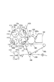
本発明に係る画像形成装置の一例であるカラー画像形成装置を図1の概略構成図に示す。図1において、第1の像担持体としての感光ドラム1としては、OPC等の感光材料がアルミニウム等のシリンダ状の基体の外周面に形成されたものを使用しており、その外径は50mmである。上記感光ドラム1は、矢印の方向に120mm/secの周速度をもって回転駆動される。
Example 1
A color image forming apparatus as an example of the image forming apparatus according to the present invention is shown in a schematic configuration diagram of FIG. In FIG. 1, as a
本明細書では、画像形成装置が行う画像形成とは、外部情報より感光ドラム1に静電潜像を形成し、それを現像して可視化して現像剤像(トナー像)とし、それを紙等の転写材Pに記録する動作であり、それが行われる工程を画像形成工程とする。
In this specification, image formation performed by the image forming apparatus means that an electrostatic latent image is formed on the
画像形成工程における画像形成動作について詳しく説明すると、まず、感光ドラム1の表面が、帯電装置としての帯電ローラ2によって、暗部電位VDとして約−700vに一様に帯電される。この帯電ローラ2には、直流電圧に交流電圧を重畳した振動電圧が印加されている。
The image forming operation in the image forming step will be described in detail. First, the surface of the
次に第1の画像情報に応じてON/OFF制御されたレーザビーム3による走査露光が施され、明部電位VLとして約−150vの第1の静電潜像が形成される。
(4) Next, scanning exposure is performed by the
このように形成された静電潜像は、回転現像装置4により、現像・可視化される。現像装置4は、現像手段として、第1色目の現像剤(トナー)としてイエロートナーが収容された第1の現像器4a、第2色目のトナーとしてマゼンタトナーが収容された第2の現像器4b、第3色目のトナーとしてシアントナーが収容された第3の現像器4c、第4色目のトナーとしてブラックトナーが収容された第4の現像器4dが搭載されており、所定の切り替え時間をもって、これら各現像器4a、4b、4c、4dを感光ドラム1に対向した現像位置へ回転移動させることで順次切り替え可能である。
静電 The electrostatic latent image thus formed is developed and visualized by the
各現像器4a〜4dである現像手段は、現像器内の各色のトナーを感光ドラム1表面へと移動させる現像剤担持体としての現像ローラ5と、現像ローラ5にトナーを供給するための回転可能な供給ローラ6と、現像ローラ5表面に担持されるトナー量を規制するための規制部材としての現像ブレード7、供給ローラ6近傍にトナーを搬送する回転可能な撹拌部材8とから構成され、更に、後に詳しく説明する画像形成履歴を記録、参照可能なフラッシュメモリ等の記憶手段としてのメモリ部Bを有している。
Developing means, each of the developing
回転現像装置4の回転によって、回転現像装置4に搭載された各現像器4a〜4dは、感光ドラム1と対向する現像位置に順次移動する。感光ドラム1に対向した現像器、ここでは現像器4aとすると、不図示のモータにより矢印の方向に現像ローラ5が回転駆動するとともに、クラッチ等を有する接離機構40により、現像器4aが感光ドラム1方向へと加圧移動させられ、現像器4aが備えた現像ローラ5が感光ドラム1表面に当接して回転する。現像ローラ5の回転周速は、感光ドラム1の回転周速と同等か、それよりも速いことが一般的である。
(4) Due to the rotation of the
現像ローラ5に対しては、不図示の高圧電源により、所定の直流バイアスが印加され、感光ドラム1上の被露光部電位とこのバイアスとの電位差により現像ローラ5上のトナーが感光ドラム1上の被露光部即ち静電潜像部分に転移することにより可視化され、現像が行なわれる。
A predetermined DC bias is applied to the developing
このように、現像ローラ5としては、このような、接離機構40によって感光ドラム1表面に押圧若しくは接触して現像を行なう接触現像方式においては、芯金の外周面にゴム等の弾性層を有する形態のものが用いられることが好ましい。
As described above, in the contact developing method in which the developing
現像ブレード7は、金属薄板にて構成され、薄板のバネ弾性を利用して、現像ローラ5表面に軽圧当接され、現像ローラ5の回転に伴い、この現像ローラ5と現像ブレード7との当接ニップ部に搬送されてくるトナーを摺擦、摩擦帯電させることにより電荷を付与させるとともに、層厚規制する。
The developing
現像ブレード7としての金属薄板の材質としては、ステンレス鋼、リン青銅等が使用可能であるが、本実施例においては、厚さ0.1mmのリン青銅薄板を用いた。
薄 As a material of the metal thin plate as the developing
尚、上記イエロートナー、マゼンタトナー、シアントナー、ブラックトナーの正規の帯電極性は負極性である。そしてまず、上記第1の静電潜像は、第1色目のトナーとしてイエロートナーが収容された第1の現像器4aにより現像、可視化される。
The normal charging polarity of the yellow toner, magenta toner, cyan toner, and black toner is negative. First, the first electrostatic latent image is developed and visualized by the first developing
可視化された感光ドラム1上のイエロートナー像は、矢印の方向に回転駆動される中間転写体としての中間転写ベルト9と対向する第1の転写部位10aにおいて、不図示の高圧電源により一次転写ローラ11に対してトナーの正規の帯電極性とは逆極性の電圧(一次転写バイアス)が印加され、中間転写ベルト9表面に静電転写(一次転写)される。
The visualized yellow toner image on the
上記中間転写ベルト9は、懸架ローラ12a、12b、12cにより支持されるとともに、上記感光ドラム1に対して、一次転写ローラ11により所定の押圧力をもって圧接されつつ、感光ドラム1の周速度と略等速の周速度をもって矢印の方向に回転駆動される。
The
尚、一次転写が終了した感光ドラム1表面に若干量残存する一次転写残留トナーは、クリーニング装置13により除去される。このクリーニング装置13は、板金等で構成された支持部材の先端部に、ウレタンゴム等で構成される弾性部材を有するクリーニングブレード13aを具備しており、上記弾性部材の先端部を上記感光ドラム1表面に対して、いわゆるカウンタ方向から所定の押圧力で当接させることにより、一次転写残留トナーを感光ドラム1表面から除去する。
(4) The primary transfer residual toner slightly remaining on the surface of the
更に、上記工程を、現像器4b〜4dを用いて、3回繰り返し、その都度、マゼンタトナーにより現像されたマゼンタトナー像、シアントナーにより現像されたシアントナー像、ブラックトナーにより現像されたブラックトナー像が順次中間転写ベルト9表面に転写、積層する。
Further, the above process is repeated three times using the developing
その後、中間転写ベルト9表面に対して離間状態にあった二次転写ローラ14を、所定の押圧力で中間転写ベルト9を介して懸架ローラ12cに圧接させて、回転駆動する。
Then, the
二次転写ローラ14に対しては、不図示の高圧電源により、トナーの正規の帯電極性とは逆極性の電圧(二次転写バイアス)が印加されることにより、第2の転写部位10bにレジローラ15により所定のタイミングをはかり搬送されてくる転写材P表面に、中間転写ベルト9表面に積層形成されたトナー像が一括転写(二次転写)され、この転写材Pは、定着装置16へと搬送され、永久画像として定着された後、機外へと排出される。
A voltage (secondary transfer bias) having a polarity opposite to the normal charge polarity of the toner is applied to the
尚、二次転写が終了した中間転写ベルト9表面に若干量残存する二次転写残留トナーは、所定のタイミングをもって中間転写ベルト9表面に当接するクリーニング装置17により除去される。
The secondary transfer residual toner slightly remaining on the surface of the
上記は1枚の転写材Pにおける画像形成工程であり、1回の画像形成とされるが、複数枚の転写材Pに対して連続して上記の画像形成工程を行い、連続して画像形成される場合がある。この複数枚連続して画像形成を行う場合は、1枚目の画像形成工程開始から最後の1枚の画像形成工程終了までを1回の画像形成とする。 The above is an image forming process on one transfer material P, which is one image formation. The image forming process is continuously performed on a plurality of transfer materials P, and the image formation is continuously performed. May be done. In the case where image formation is continuously performed on a plurality of sheets, one image formation is performed from the start of the image formation step of the first sheet to the end of the image formation step of the last sheet.
上記の画像形成装置において、回転現像装置4に備えられた現像器4a〜4dに収納された現像剤である、イエロートナー、マゼンタトナー、シアントナー、ブラックトナーとしては、一成分非磁性トナーが用いられており、上記に説明したように、現像ローラ5の回転により、感光ドラム1の静電潜像部分にトナーを送り込む接触現像方式を採用している。
In the above-described image forming apparatus, one-component non-magnetic toner is used as the yellow toner, magenta toner, cyan toner, and black toner, which are the developers stored in the developing
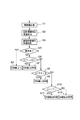
ここで、図18を参照して画像形成装置のプロセス制御部と駆動部(モータなど)、現像位置、回転現像装置4との関係を簡単に説明する。
Here, with reference to FIG. 18, the relationship between the process control unit of the image forming apparatus, the driving unit (such as a motor), the developing position, and the
プロセス制御部Pは駆動部K1〜K3に対して駆動信号を送信し、駆動部K1よって駆動信号を受信して現像位置の現像ローラ5を回転駆動し、駆動部K2によって回転現像装置4を回転駆動する。そして、現像ローラ5を回転させて現像ブレード7と摩擦させることによってトナーに電荷を付与する。又、駆動部K3によってクラッチ等の接離機構40が動作することによって、回転現像装置4を矢印方向に動作させて感光ドラム1に対して当接及び離間を行う。
The process control unit P transmits a driving signal to the driving units K1 to K3, receives the driving signal from the driving unit K1, rotates the developing
又、プロセス制御部Pは、制御部内の読み書き手段(読み書き制御部)Cによって記憶手段(メモリ部)Bと通信を行い各現像手段4a〜4dに設けられたメモリ部Bに対して情報の読み書きを行う。
The process control unit P communicates with a storage unit (memory unit) B by a read / write unit (read / write control unit) C in the control unit to read / write information from / to a memory unit B provided in each of the developing
尚駆動部を複数持つ構成で説明したが、駆動部を1つにして制御を行うことも可能である。 Although the description has been given of a configuration having a plurality of drive units, it is also possible to perform control with one drive unit.
又、次に、本実施例で用いたトナーについて説明する。 Next, the toner used in this embodiment will be described.
本発明に係るトナーは、例えば懸濁重合法により製造され、その粒径は約5〜7μmの実質的球形であり、低軟化物質(ワックス成分)を内包した、一成分非磁性微粒径重合トナーである。 The toner according to the present invention is produced by, for example, a suspension polymerization method, has a substantially spherical particle diameter of about 5 to 7 μm, and contains a low-softening substance (wax component). Toner.
透過電子顕微鏡(TEM)を用いたトナー粒子の断層面観察において、ワックス成分が結着樹脂と相溶しない状態で、実質的に球状及び/又は紡錘形で、結着樹脂から盛り上がるような島状に分散されていることが好ましい。 In observing the tomographic plane of the toner particles using a transmission electron microscope (TEM), the wax component is substantially spherical and / or spindle-shaped, in an island-like shape protruding from the binder resin in a state in which the wax component is not compatible with the binder resin. Preferably they are dispersed.
ワックス成分を上記の如く分散させ、トナー中に内包化させることによりトナーの劣化や画像形成装置への汚染等を防止することができるので、良好な帯電性が維持され、ドット再現に優れたトナー像を長期にわたって形成し得ることが可能となる。又、加熱時にはワックス成分が効率よく作用するため、低温定着性と耐オフセット性を満足なものとする。 By dispersing the wax component as described above and encapsulating the toner in the toner, it is possible to prevent deterioration of the toner and contamination of the image forming apparatus. An image can be formed over a long period of time. In addition, since the wax component acts efficiently during heating, low-temperature fixability and offset resistance are satisfied.
本発明において、トナー粒子の断層面を観察する具体的な方法としては、常温硬化性のエポキシ樹脂中にトナー粒子を充分分散させた後、温度40℃の雰囲気中で2日間硬化させることにより得られた効果物を四三酸化ルテニウム、必要により四三酸化オスミウムを併用し染色を施した後、ダイヤモンド歯を備えたミクロトームを用い薄片状のサンプルを切り出し、透過電子顕微鏡(TEM)を用いトナー粒子の断層形態を観察する。 In the present invention, as a specific method of observing the tomographic plane of the toner particles, the toner particles are obtained by sufficiently dispersing the toner particles in a cold-setting epoxy resin and then curing the same in an atmosphere at a temperature of 40 ° C. for 2 days. The obtained effect is dyed using ruthenium tetroxide and, if necessary, osmium tetroxide in combination, a flaky sample is cut out using a microtome with diamond teeth, and toner particles are obtained using a transmission electron microscope (TEM). Observation of the fault morphology.
本発明においては、用いるワックス成分と外殻を構成する樹脂との若干の結晶化度の違いを利用して材料間のコントラストを付けるため、四三酸化ルテニウム染色法を用いることが好ましい。 In the present invention, it is preferable to use a ruthenium tetroxide dyeing method in order to provide a contrast between materials by utilizing a slight difference in crystallinity between the wax component used and the resin constituting the outer shell.
本発明に係るワックス成分は、示差走査熱量計により測定されるDSC曲線において、昇温時に40〜130℃の領域に最大吸熱ピークを有するものが用いられる。この温度領域に最大吸熱ピークを有することにより低温定着に大きく貢献しつつ、離型性をも効果的に発現する。 (4) As the wax component according to the present invention, one having a maximum endothermic peak in a region of 40 to 130 ° C. at the time of temperature rise in a DSC curve measured by a differential scanning calorimeter is used. By having a maximum endothermic peak in this temperature range, it greatly contributes to low-temperature fixing, and also effectively expresses releasability.
この最大吸熱ピークが40℃未満であると、ワックス成分の自己凝集力が弱くなり、結果として耐高温オフセット性が悪化すると共に、グロスが高くなりすぎる。一方、最大吸熱ピークが130℃を越えると定着温度が高くなると共に、定着画像表面を適度に平滑化させることが困難となるため、特にカラートナーに用いた場合には混色性低下の点から好ましくない。 (4) When the maximum endothermic peak is less than 40 ° C., the self-cohesive force of the wax component becomes weak, resulting in deterioration of high-temperature offset resistance and excessively high gloss. On the other hand, if the maximum endothermic peak exceeds 130 ° C., the fixing temperature becomes high, and it becomes difficult to appropriately smooth the surface of the fixed image. Absent.
更に、水系媒体中で造粒、重合を行い重合方法により直接トナーを得る場合、最大吸熱ピーク温度が高いと、主に造粒中にワックス成分が析出する等の問題を生じ、好ましくない。 Further, when granulation and polymerization are performed in an aqueous medium to directly obtain a toner by a polymerization method, if the maximum endothermic peak temperature is high, a problem such as precipitation of a wax component mainly during granulation is not preferred.
ワックス成分の最大吸熱ピーク温度の測定は、「ASTMD3418−8」に準じて行なう。測定には、例えば、パーキンエルマー社製DSC−7を用いる。装置検出部の温度補正はインジウムと亜鉛の融点を用い、熱量の補正についてはインジウムの融解熱を用いる。測定サンプルにはアルミニウム製パンを用い、対照用に空パンをセットし、1回昇温−降温させることにより前履歴をとった後、昇温速度10℃/minで測定を行う。 最大 The maximum endothermic peak temperature of the wax component is measured according to “ASTMD3418-8”. For the measurement, for example, DSC-7 manufactured by PerkinElmer is used. The temperature correction of the device detection unit uses the melting points of indium and zinc, and the correction of the calorific value uses the heat of fusion of indium. An aluminum pan was used as a measurement sample, an empty pan was set as a control, and a pre-history was obtained by raising and lowering the temperature once, and then the measurement was performed at a heating rate of 10 ° C./min.
上記ワックス成分としては、具体的にはパラフィンワックス、ポリオレフィンワックス、フィッシャートロピッシュワックス、アミドワックス、高級脂肪酸、エステルワックス、及びこれらの誘導体、又はこれらのグラフト/ブロック化合物等が利用できる。 Specific examples of the wax component include paraffin wax, polyolefin wax, Fischer-Tropsch wax, amide wax, higher fatty acid, ester wax, derivatives thereof, and graft / block compounds thereof.
本発明に係るトナーは、画像解析装置で測定した形状係数SF1の値が100〜160であり、形状係数SF2の値が100〜140であることが好ましく、形状係数SF1の値が100〜140であり、形状係数SF2の値が100〜120であれば更に好ましい。 In the toner according to the present invention, the value of the shape factor SF1 measured by the image analyzer is preferably from 100 to 160, the value of the shape factor SF2 is preferably from 100 to 140, and the value of the shape factor SF1 is preferably from 100 to 140. It is more preferable that the value of the shape factor SF2 is 100 to 120.
又、上記の条件を満たし、且つ(SF2)/(SF1)の値を1.0以下とすることにより、トナーの諸特性のみならず、画像解析装置とのマッチングがきわめて良好なものとなる。 (4) By satisfying the above conditions and setting the value of (SF2) / (SF1) to 1.0 or less, not only the various characteristics of the toner but also the matching with the image analysis device become extremely good.
トナー像の転写効率を高めるためには、形状係数SF2は、100〜140であり、(SF2)/(SF1)の値が1.0以下であるのが好ましい。 In order to increase the transfer efficiency of the toner image, the shape factor SF2 is preferably 100 to 140, and the value of (SF2) / (SF1) is preferably 1.0 or less.
本発明に用いられる形状係数を示すSF1、SF2とは、日立製作所製FE−SEM(S−800)を用い、倍率500倍に拡大したトナー像を100個無作為にサンプリングし、その画像情報をインターフェースを介してニコレ社製画像解析装置(Luzex3)に導入して解析を行い、下式より算出し得られた値と定義されるものである。 SF1 and SF2 indicating the shape factors used in the present invention are obtained by randomly sampling 100 toner images magnified 500 times using FE-SEM (S-800) manufactured by Hitachi, Ltd. The value is defined as a value obtained by performing an analysis by introducing the image into an image analysis device (Luzex3) manufactured by Nicolet via an interface, and calculating from the following equation.
SF1={(MXLNG)2/AREA}×(π/4)×100
SF2={(PERI)2/AREA}×(1/4π)×100
AREA:トナー投影面積、
MXLNG:絶対最大長、
PERI:周長
SF1 = {(MXLNG) 2 / AREA} × (π / 4) × 100
SF2 = {(PERI) 2 / AREA} × (1 / 4π) × 100
AREA: toner projection area,
MXLNG: absolute maximum length,
PERI: circumference
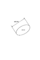
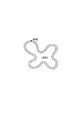
トナーの形状係数SF1は図2に示したトナー形状におけるMXLNGとAREAと、上記のSF1の式を参照すれば理解できるように、トナー粒子の丸さの度合を示し、数値が大きくなると、球形から徐々に不定形となる。SF2は図3に示したトナー形状におけるPERIとAREAと、上記のSF2の式を参照すれば理解できるように、トナー粒子の凹凸度合を示し、数値が大きくなると、トナー表面の凹凸が顕著となる。 As can be understood by referring to MXLNG and AREA in the toner shape shown in FIG. 2 and the equation of SF1 described above, the shape factor SF1 of the toner indicates the degree of roundness of the toner particles. It gradually becomes amorphous. SF2 indicates the degree of unevenness of the toner particles as can be understood by referring to the PERI and AREA in the toner shape shown in FIG. 3 and the equation of SF2. As the numerical value increases, the unevenness of the toner surface becomes remarkable. .
形状係数SF1が160を越える場合には、転がり抵抗が低くなるためトルクが増大したり、摩擦が大きくなるため、摩擦熱が大きくなり熱劣化を起こしやすい。又、形状係数SF2が140より大きく、(SF2)/(SF1)の値が1.0を超える場合、トナー粒子の表面が滑らかではなく、多数の凹凸をトナー粒子が有しており、感光ドラム1から転写材Pへの転写効率が低下する傾向にある。 (4) When the shape factor SF1 exceeds 160, the rolling resistance is reduced and the torque is increased, and the friction is increased, so that the frictional heat is increased and the thermal deterioration is likely to occur. When the shape factor SF2 is larger than 140 and the value of (SF2) / (SF1) exceeds 1.0, the surface of the toner particles is not smooth, and the toner particles have many irregularities. The transfer efficiency from No. 1 to the transfer material P tends to decrease.
更には、本発明で使用するトナー粒子としては、トナー粒子表面が外添剤で被覆された、ものを用い、トナーが所望の帯電量が付与されるようにすることが好ましい。 Further, as the toner particles used in the present invention, it is preferable to use toner particles whose surface is coated with an external additive so that the toner has a desired charge amount.
よって、トナー表面の外添剤被覆率が、5〜99%、更には10〜99%であることが好ましい。 Therefore, the external additive coverage on the toner surface is preferably 5 to 99%, more preferably 10 to 99%.
トナー表面の外添剤被覆率は、次のようにして求められる。日立製作所製FE−SEM(S−800)を用い、トナー像を100個無作為にサンプリングし、その画像情報をインターフェースを介してニコレ社製画像解析装置(Lusex3)に導入する。そこで得られる画像情報は、トナー粒子表面部分と外添剤部分との明度が異なるので、2値化して、外添剤部分の面積SGとトナー粒子部分の面積(外添剤部分の面積も含む)STに分けて求められ、それらを用いて、外添材被覆率を下記式により算出する。 外 The coverage of the external additive on the toner surface is determined as follows. Using an FE-SEM (S-800) manufactured by Hitachi, 100 toner images are randomly sampled, and the image information is introduced into an image analyzer (Lusex3) manufactured by Nicole via an interface. The image information obtained therefrom is different in brightness between the toner particle surface portion and the external additive portion, so that the image information is binarized, and the area SG of the external additive portion and the area of the toner particle portion (including the area of the external additive portion are included). ) It is obtained by dividing into ST, and using them, the external additive material coverage is calculated by the following formula.
外添剤被覆率(%)=(SG/ST)×100 被覆 Coating rate of external additive (%) = (SG / ST) × 100
本発明に使用される外添剤としては、トナーに添加した時の耐久性の点から、トナー粒子の重量平均径の1/10以下の粒径であることが好ましい。この添加剤の粒径とは、電子顕微鏡におけるトナー粒子の表面観察により求めたその平均粒径を意味する。 (4) The external additive used in the present invention preferably has a particle size of 1/10 or less of the weight average particle size of the toner particles from the viewpoint of durability when added to the toner. The particle diameter of the additive means an average particle diameter thereof obtained by observing the surface of the toner particles with an electron microscope.
外添剤としては、例えば、金属酸化物(酸化アルミニウム、酸化チタン、チタン酸ストロンチウム、酸化セリウム、酸化マグネシウム、酸化クロム、酸化錫、酸化亜鉛等)、窒化物(窒化ケイ素等)、炭化物(炭化ケイ素等)、金属塩(硫酸カルシウム、硫酸バリウム、炭酸カルシウム等)、脂肪酸金属塩(ステアリン酸亜鉛,ステアリン酸カルシウム等)、カーボンブラック、シリカ等が用いられる。 Examples of the external additive include metal oxides (such as aluminum oxide, titanium oxide, strontium titanate, cerium oxide, magnesium oxide, chromium oxide, tin oxide, and zinc oxide), nitrides (such as silicon nitride), and carbides (such as carbonized). Silicon, etc., metal salts (calcium sulfate, barium sulfate, calcium carbonate, etc.), fatty acid metal salts (zinc stearate, calcium stearate, etc.), carbon black, silica and the like are used.
本発明においては、トナー粒子中(100重量部)に補助粒子を外添した。外添した補助粒子は、負極性外添剤としてシリカを1重量部、正極性外添剤として酸化チタン0.1重量部である。特に、正極性外添剤を加えた場合には、トナーの流動性の調節、トナーへの帯電性付与が可能となる。 In the present invention, auxiliary particles were externally added to the toner particles (100 parts by weight). The externally added auxiliary particles contained 1 part by weight of silica as a negative external additive and 0.1 part by weight of titanium oxide as a positive external additive. In particular, when a positive external additive is added, the fluidity of the toner can be adjusted and the toner can be charged.
これら外添剤の添加量については、トナー粒子100重量部に対し、0.01〜10重量部が用いられ、好ましくは、0.05〜5重量部が用いられる。 The amount of these external additives is 0.01 to 10 parts by weight, preferably 0.05 to 5 parts by weight, based on 100 parts by weight of the toner particles.
外添剤の添加量が0.01重量部未満の場合には、一成分系現像剤の流動性が悪化し、転写及び現像の効率が低下してしまい、画像の濃度ムラや画像部周辺にトナーが飛び散ってしまう、所謂飛び散りが発生する。 When the addition amount of the external additive is less than 0.01 part by weight, the fluidity of the one-component developer is deteriorated, the efficiency of transfer and development is reduced, and the density unevenness of the image and the periphery of the image area are reduced. So-called scattering occurs in which toner scatters.
一方、外添剤の量が10重量部を越える場合には、過多な外添剤が感光ドラムや現像ローラに付着してトナーへの帯電性を悪化させたり、画像を乱したりする。 On the other hand, when the amount of the external additive exceeds 10 parts by weight, an excessive amount of the external additive adheres to the photosensitive drum or the developing roller, thereby deteriorating the chargeability to the toner or disturbing the image.
これら外添剤は、単独で用いても、又、複数併用しても良い。又、各々疎水化処理を行ったものが、より好ましい。 These external additives may be used alone or in combination. Further, those subjected to a hydrophobic treatment are more preferable.
本実施例のような一成分非磁性トナーを用いた接触現像方式をとる画像形成装置においては、従来例に説明したようなトナーの帯電量の不足による画像濃度不足、画像濃度の不均一等の画像不良が発生することがある。 In an image forming apparatus employing a contact development method using a one-component non-magnetic toner as in the present embodiment, image density insufficiency due to insufficient toner charge amount, image density non-uniformity, etc. as described in the conventional example. Image defects may occur.
そこで、本発明においては、図1に示されているとおり、現像手段4a〜4dには、各々、現像ローラ5、供給ローラ6、現像ブレード7、撹拌部材8等に加え、画像形成履歴を記録、参照可能なフラッシュメモリ等の記憶手段としてのメモリ部Bが備えられており、前回の画像形成において使用された現像手段4a〜4dのメモリ部Bには、上記の画像形成工程に従ってなされた前回の画像形成終了時刻を記憶している。画像形成装置製造時から初めて使用される現像手段の場合は、その現像手段のメモリ部Bには、画像形成履歴なしと記録されている。
Therefore, in the present invention, as shown in FIG. 1, the image forming history is recorded on the developing means 4a to 4d in addition to the developing
又、連続画像形成を含む、上記の1回分の画像形成を開始する前には、不図示のパーソナルコンピュータ等のホスト機器から画像形成指令が発信されてから行われる、定着装置の加熱等の所謂前回転と称される準備工程が設けられる。 Before starting the above-described one-time image formation including continuous image formation, so-called heating of a fixing device or the like, which is performed after an image formation command is transmitted from a host device such as a personal computer (not shown). A preparation step called pre-rotation is provided.
そして、製造された画像形成装置において、ある現像手段の使用した画像形成が2回目以降である場合は、この現像手段を使用した1回分の画像形成を開始する時、準備工程において、この記憶手段に記憶された前回の画像形成終了時刻から今回の不図示のパーソナルコンピュータ等のホスト機器から画像形成指令発信時刻までの経過時間を算出して、その経過時間に応じてこの現像手段における現像ローラの回転時間を、後に図5のフローチャートを用いて説明するような本発明に係る制御方法にて制御することによって、トナーの帯電量不足を回避するものである。 In the manufactured image forming apparatus, if the image formation using a certain developing unit is performed for the second time or later, when the image forming for one time using this developing unit is started, in the preparation step, the storage unit is used. The time elapsed from the previous image formation end time stored in the storage unit to the image formation command transmission time from a host device such as a personal computer (not shown) is calculated this time, and the developing roller of the developing means in this developing unit is calculated in accordance with the elapsed time. By controlling the rotation time by a control method according to the present invention, which will be described later with reference to the flowchart of FIG. 5, an insufficient charge amount of the toner is avoided.
そこで、次に、本発明の画像形成装置の制御方法に関わる画像形成装置の現像器に設けられたメモリ部Bと画像形成装置本体との通信について図4を参照しつつ説明する。 Therefore, communication between the memory unit B provided in the developing device of the image forming apparatus and the main body of the image forming apparatus according to the control method of the image forming apparatus of the present invention will be described next with reference to FIG.
メモリ部Bには情報を記憶するための記憶部Fが設けられている。この記憶部Fには、前述したようにフラッシュメモリやEEPROM、又、FERAM(強誘電体メモリ)等の不揮発性の記憶素子であればどのような素子でも適用可能である。このメモリ部Bに対しては、画像形成装置Aに具備された読み書き手段(読み書き制御部)Cによりアクセス可能となる。 The memory unit B is provided with a storage unit F for storing information. As described above, any element such as a flash memory, an EEPROM, or a non-volatile storage element such as a FERAM (ferroelectric memory) can be applied to the storage unit F. The memory unit B can be accessed by a read / write unit (read / write control unit) C provided in the image forming apparatus A.
画像形成装置本体Aにおいては、画像形成をコントロールするためのプロセス制御部Pを有しており、プロセス制御部Pには、メモリ部Bの記憶部Fにアクセスして情報を読み出すか、又は、書込み制御を行なうための読み書き制御部Cを有しており、本実施例においては、画像形成装置の画像形成工程が終了した時点での日付情報(日時)を記憶部Fの所定の領域に記憶させる。 The image forming apparatus main body A has a process control unit P for controlling image formation. The process control unit P accesses the storage unit F of the memory unit B to read information, or A read / write control unit C for performing write control is provided. In the present embodiment, date information (date and time) when the image forming process of the image forming apparatus is completed is stored in a predetermined area of the storage unit F. Let it.
又、読み書き制御部Cは、画像形成装置のプロセスを制御するプロセス制御部P(CPU)が読み書き制御を行なっても良いし、別の専用の制御部を設けて制御してもよい。 The read / write control unit C may be controlled by a process control unit P (CPU) that controls a process of the image forming apparatus, or may be controlled by providing another dedicated control unit.
又、読み書き制御部Cとメモリ部Bとの通信は、信号線を接続(又は接触)させて通信を行なっても良いし、アンテナを用いた電磁波による通信や光通信等の無線で通信する方式であっても良い。 The communication between the read / write control unit C and the memory unit B may be performed by connecting (or contacting) a signal line, or may be performed by wireless communication such as communication using an electromagnetic wave using an antenna or optical communication. It may be.
ここで、本発明に係る画像形成装置の制御方法に従った動作、特に、1回分の画像形成前の準備工程における制御方法に従った動作について、図5のフローチャートを用いて説明する。 Here, the operation according to the control method of the image forming apparatus according to the present invention, in particular, the operation according to the control method in the preparation process before one-time image formation will be described with reference to the flowchart of FIG.
尚、1回分の画像形成とは、上記に説明したように、1枚の転写材Pにおける画像形成工程を行う動作か、又は、複数枚の転写材Pに対して上記の画像形成工程を繰り返し行う動作のこととする。そして、この、準備工程が行われる、1回分の画像形成前とは、不図示のパーソナルコンピュータ等のホスト機器から画像形成指令が発信されてから、少なくとも、感光ドラム1に静電潜像が形成され、始動する現像手段、ここでは第1色目の現像器4aが動作するまでの時間帯のことを意味する。
As described above, one-time image formation is an operation of performing an image forming process on one transfer material P, or repeating the image forming process on a plurality of transfer materials P. The operation to be performed. Before the image formation for one time in which the preparation process is performed, at least an electrostatic latent image is formed on the
まず、ステップS1で、前回の1回分の画像形成が終了すると直ちに、画像形成装置Aの読み書き制御部Cにより、ステップS2で、各現像器4a〜4dの記憶媒体に画像形成終了時刻が記録される。尚、ここでは、前回の画像形成には、現像器4a〜4dの全てが使用されたこととする。
First, in step S1, immediately after the previous one-time image formation is completed, the read / write control unit C of the image forming apparatus A records the image formation end time in the storage medium of each of the developing
尚、この時には現像手段4a〜4dの接離機構40により現像ローラ5は、感光ドラム1より離接している状態である。
At this time, the developing
そして、次に、ステップS3で、パーソナルコンピュータ等のホスト機器から新たな画像形成指令が発信され、それを受けると、ステップS4で、読み書き制御部Cを介して記憶手段Bに記録されている、前回の画像形成終了時刻から、今回の画像形成指令が受信された時刻である画像形成開始時刻までの経過時間Tを算出し、このTの値に応じて、今回の画像形成前に行なわれる準備工程において現像ローラ5を空回転させるべき時間を決定する。
Then, in step S3, a new image forming command is transmitted from a host device such as a personal computer, and when it is received, in step S4, the command is stored in the storage means B via the read / write control unit C. The elapsed time T from the previous image formation end time to the image formation start time, which is the time at which the current image formation command is received, is calculated, and the preparation performed before the current image formation is performed according to the value of T. In the process, the time for idling the developing
尚、空回転とは、回転現像装置4を感光ドラムに対して離間させた状態で現像ローラ5を回転させる動作であり、これによってトナーに電荷を付与する。
The idle rotation is an operation of rotating the developing
そして、例えばT=3時間の場合にあっては、T≦2のステップS5でNOであり、ステップS7に進んで、T≦4かどうかで、YESと判定されるため、ステップS8に進み、各現像器4a〜4dに装着された現像ローラ5が矢印の方向に5秒間空回転する。
Then, for example, in the case of T = 3 hours, NO is determined in step S5 of T ≦ 2, the process proceeds to step S7, and YES is determined if T ≦ 4, so the process proceeds to step S8. The developing
まずイエロートナーが収容された第1の現像器4aが、感光ドラム1と対向する現像位置に移動し、現像ローラ5が感光ドラム1表面から離間した状態で、不図示のモータにより5秒間にわたり、現像ローラ5が回転駆動する。
First, the first developing
これが終了すると、再び現像装置4が矢印の方向に回転し、マゼンタトナーが収容された第2の現像器4bが、感光ドラム1と対向する現像位置に移動し、現像ローラ5が感光ドラム1表面から離間した状態で、不図示のモータにより5秒間にわたり、回転駆動する。
When this is completed, the developing
以後、シアントナーが収容された第3の現像器4c、ブラックトナーが収容された第4の現像器4dに関しても同様に、現像ローラ5が不図示のモータにより5秒間にわたり回転駆動させられた後、正規の画像形成工程が開始される。
Thereafter, the third developing
T≦2のステップS5でYESの場合には、ステップS6に進み、3秒間にわたって現像ローラ5が回転駆動する。又、T≦4のステップS7でNOの場合には、ステップS9に進み、10秒間にわたって現像ローラ5を回転駆動する。
If YES in step S5 where T ≦ 2, the process proceeds to step S6, and the developing
尚、回転のON/OFFは、画像形成装置内のプロセス制御手段Pによって制御される。 (4) ON / OFF of the rotation is controlled by a process control unit P in the image forming apparatus.
図5のフローチャートに従って以上に説明したように、本発明の画像形成装置の制御方法においては、現像手段に設けられた記憶手段が、この現像手段を用いた1回の画像形成を終了した時刻を記憶し、次の1回分の画像形成前の準備工程において、前回の画像形成工程を終了した時刻から次の画像形成を開始した時刻までの時間を算出する工程が設けられる。そして、この画像形成の終了と開始との時間間隔である、経過時間の長さによって、前回転中の現像ローラの回転時間を決定する工程が設けられる。 As described above with reference to the flowchart of FIG. 5, in the control method of the image forming apparatus according to the present invention, the storage unit provided in the developing unit stores the time when one image formation using this developing unit is completed. There is provided a step of storing and calculating the time from the time when the previous image forming step is completed to the time when the next image forming is started in the preparatory step before forming the next one image. Then, a step of determining the rotation time of the developing roller during the previous rotation is provided based on the length of the elapsed time, which is the time interval between the end and the start of the image formation.
尚、画像形成装置製造から初めて使用される現像手段においては、ステップS7のT≦4時間において、NOと判断され、現像ローラ5は、10秒間回転される。
In the developing means used for the first time since the manufacture of the image forming apparatus, NO is determined in T ≦ 4 hours in step S7, and the developing
これにより、例えば長時間の放置状態を経た後に画像形成を行なう場合にあっても、画像形成工程前に、予めトナーに充分な電荷を付与することが可能となり、画像濃度が低い、もしくは画像濃度が不均一であるといった不具合の発生を防止することが可能となる。 Thus, for example, even when image formation is performed after a long standing state, it is possible to apply sufficient charge to the toner before the image forming process, and to reduce the image density or the image density. Can be prevented from being inconsistent.
又、上記現像ローラ5の空回転工程を、現像ローラ5が感光ドラム1表面から離間した状態で行なうため、感光ドラム1表面へのトナーの不必要な転移や機内飛散等の不具合の発生も防止可能となる。
In addition, since the idling step of the developing
上記は、4台の現像器4a〜4d全てを使用して画像形成がなされる場合であるが、単色画像形成時等、全ての現像器が使用されない場合があり、この時動作しない現像器が存在する。こういう場合、それぞれの現像器について経過時間Tが違った数値になることもあるが、画像履歴を記憶する記憶手段Bが現像器毎に備えられているため、現像器毎に図5に示したような動作を行い、その現像器毎に経過時間Tを算出し、それぞれにおける準備工程での回転時間を定めることができる。
The above is a case where image formation is performed using all the four developing
実施例2
以下に、本発明に係る画像形成装置及びその制御方法の他の実施例を示すが、実施例に述べた部材と同一の部材については同一の番号を付し説明を省略する。
Example 2
Hereinafter, other embodiments of the image forming apparatus and the control method thereof according to the present invention will be described. The same members as those described in the embodiments are denoted by the same reference numerals and description thereof will be omitted.
本実施例の画像形成装置においては、各現像器4a〜4d内に残存しているトナー量を検知する現像剤残量検知手段(トナー量検知手段)が設けられ、画像形成装置の制御方法に従って、1回の画像形成前の準備工程に行なわれる各現像器4a〜4dの現像ローラ5の空回転時間を、各現像器4a〜4d内に残存しているトナー量に応じて可変であることを特徴とする。
In the image forming apparatus according to the present embodiment, a developer remaining amount detecting unit (toner amount detecting unit) for detecting an amount of toner remaining in each of the developing
この目的とするところは、現像器4a〜4d内に残存しているトナー量によって、現像ローラ5の空回転時間を調整して、トナーに対し、過度なストレスを及ぼさないように制御することにある。現像時の、トナーに対する電荷付与性は、現像器4a〜4d内に残存しているトナー量によって差異がある。即ち、トナー残量が多く、均一な電荷付与が比較的困難な場合には、現像ローラ5の空回転時間を長く設定することにより充分な電荷付与を行ない、又、トナー残量が少なく、均一な電荷付与が比較的容易な場合には、現像ローラ5の空回転時間を短く設定する。
The purpose is to control the idle rotation time of the developing
各現像器4a〜4d内に残存しているトナー量を検出する現像剤残量検知手段(トナー量検知手段)としては、周知の圧電センサ方式、磁気センサ方式、光学検知方式、アンテナ検知方式等が用いられるが、本実施例においては、図6に示すように、現像器4a〜4dの所定部を光が通過するように、光を射出する発光素子21と、その光を受ける受光素子22とが画像形成装置A内に配設され、現像器4a〜4dの光路上には透光性の窓23が設けられており、トナーの撹拌部材8の回転に同期して透光性の窓を拭き取り、その際に検知される受光量の変化で現像器内のトナー残量を検知する光学検知手段を用いた。
As a developer remaining amount detecting means (toner amount detecting means) for detecting an amount of toner remaining in each of the developing
尚、発光素子21及び受光素子22は、画像形成装置A内のどこに幾対設けられてもよく、各現像器4a〜4d毎に計4対設けられても、全ての現像器4a〜4dの窓に光が通過するように1対だけ設けられてもよい。
The
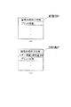
図7は、メモリ部Bの記憶部Fに画像形成装置の画像形成工程が終了した時点での日付情報(日時)に加えて、トナー残量情報Mをも記憶していることが示されている。トナー残量検知がなされない場合は、図7(a)に示すように、画像形成終了時刻及びプリント枚数が記憶されているが、トナー残量検知が行われると、図7(b)のように、トナー残量が画像形成終了時刻の次に書き込まれる。 FIG. 7 shows that the storage unit F of the memory unit B stores toner remaining amount information M in addition to the date information (date and time) when the image forming process of the image forming apparatus is completed. I have. When the remaining amount of toner is not detected, the image forming end time and the number of prints are stored as shown in FIG. 7A, but when the remaining amount of toner is detected, as shown in FIG. 7B. Next, the remaining amount of toner is written after the image forming end time.
ここで、本発明に係る画像形成装置の制御方法に従った動作、特に画像形成前の準備工程における制御方法に従った動作に関し、図8を参照しつつ説明する。 Here, the operation according to the control method of the image forming apparatus according to the present invention, particularly the operation according to the control method in the preparation process before image formation, will be described with reference to FIG.
まず、ステップS1で、現在行なわれている画像形成工程が終了すると直ちに、ステップS2で、画像形成装置の読み書き手段である、図4に示される読み書き制御部Cにより、各現像器4a〜4dのメモリ部Bの記憶部Fに画像形成終了時刻が記録されるとともに、ステップS3で、前記トナー残量検知手段により検出された各現像器4a〜4d内のトナー残量情報Mが記録される。
First, in step S1, immediately after the currently performed image forming process is completed, in step S2, the read / write control unit C shown in FIG. 4, which is a read / write unit of the image forming apparatus, controls each of the developing
尚、この時には現像手段4a〜4dの接離機構40により現像ローラ5は、感光ドラム1より離接している状態である。
At this time, the developing
そして次に、ステップS4で、パーソナルコンピュータ等のホスト機器から新たな画像形成指令を受けると、ステップS5で、読み書き制御部Cを介して記憶手段Bに記録されている、先の画像形成終了時刻からの経過時間Tを算出するとともに、このTの値と、同時に読み出した各トナー残量情報Mの値とに応じて、画像形成工程前に現像ローラ5を空回転させるべき時間が決定される。
Next, in step S4, when a new image formation command is received from a host device such as a personal computer, in step S5, the previous image formation end time recorded in the storage unit B via the read / write control unit C Is calculated, and the time to idle the developing
そして例えばT=3時間であり、イエロートナー残量40%、マゼンタトナー残量80%の場合にあっては、T≦2のステップS6でNOと判定され、T≦4のステップS10に進み、YESと判定され、ステップS11に進む。更に、イエロートナーが40%であるから、イエローの場合は、M≦50%のステップS11でYESと判定され、ステップS12に進む。よって、まずイエロートナーが収容された現像器4aが、図1の矢印の方向に回転して、感光ドラム1と対向する現像位置に移動し、現像ローラ5が感光ドラム表面から離間した状態で、不図示のモータにより3秒間にわたり、現像ローラ5が空回転駆動させられる。
For example, when T = 3 hours, the remaining amount of yellow toner is 40%, and the remaining amount of magenta toner is 80%, NO is determined in step S6 of T ≦ 2, and the process proceeds to step S10 of T ≦ 4. The determination is YES, and the process proceeds to step S11. Further, since the yellow toner is 40%, in the case of yellow, YES is determined in step S11 where M ≦ 50%, and the process proceeds to step S12. Therefore, first, the developing
これが終了すると、次に、本実施例ではマゼンタの場合は、M≦50%のステップS11でNOと判定されるので、ステップS13に進み、マゼンタトナーが収容された第2の現像器4bが、図1の矢印の方向に回転して、感光ドラム1と対向する現像位置に移動し、現像ローラ5が感光ドラム1表面から離間した状態で、不図示のモータにより5秒間にわたり、空回転駆動する。
When this is completed, next, in the case of magenta in the present embodiment, NO is determined in step S11 of M ≦ 50%, and the process proceeds to step S13, where the second developing
以後、シアントナーが収容された第3の現像器4c、ブラックトナーが収容された第4の現像器4dに関しても同様に、トナー残量に応じた時間にわたり、各々の現像ローラ5が不図示のモータにより空回転駆動させられた後、正規の画像形成が開始される。
Thereafter, with respect to the third developing
本実施例の画像形成装置では、ステップS6でT≦2時間と判断された時に、ステップS7に進み、M≦50%でYESの時は、ステップS8で現像ローラ5の空回転時間は2秒間、NOの時は、ステップS9に進み、現像ローラ5の空回転時間は3秒間となる。
In the image forming apparatus of this embodiment, when it is determined in step S6 that T ≦ 2 hours, the process proceeds to step S7, and when M ≦ 50% and YES, the idling time of the developing
そして、前回の画像形成終了から経過時間が長く、ステップS10でT≦4時間で、NOと判断された場合は、ステップS14に進み、M≦50%で、YESの時はステップS15で、現像ローラ5の空回転時間は7秒となり、NOの時は、ステップS16で、現像ローラの空回転時間は10秒となる。
Then, the elapsed time from the end of the previous image formation is long, T ≦ 4 hours in step S10, if NO is determined, the process proceeds to step S14, if M ≦ 50%, and if YES, the process proceeds to step S15. The idle rotation time of the
以上説明したように、本実施例では、画像形成装置の制御方法において、経過時間Tと現像器内のトナー残量情報Mに基づいて空回転時間を決定する工程が設けられている。 As described above, in this embodiment, in the control method of the image forming apparatus, a step of determining the idle rotation time based on the elapsed time T and the remaining toner information M in the developing device is provided.
このように、前回の画像形成終了後の経過時間と共に、トナー残量に相関させた制御を行うことにより、長時間の放置状態を経た後に画像形成を行なう場合にあっても、各色毎に画像形成前に、予めトナーに充分な電荷を付与することが可能となり、画像濃度が低い、もしくは画像濃度が不均一であるといった不具合の発生を防止することが可能となる。 In this way, by performing control in correlation with the remaining amount of toner together with the elapsed time after the end of the previous image formation, even if image formation is performed after a long period of idle state, image formation is performed for each color. Before formation, a sufficient charge can be applied to the toner in advance, and it is possible to prevent problems such as low image density or uneven image density.
又、上記現像ローラの空回転工程を、現像ローラが感光ドラム表面から離間した状態で行なうため、感光ドラム表面へのトナーの不必要な転移や機内飛散等の不具合の発生も防止可能となる。 Further, since the idling step of the developing roller is performed while the developing roller is separated from the surface of the photosensitive drum, it is possible to prevent problems such as unnecessary transfer of toner to the surface of the photosensitive drum and scattering inside the machine.
尚、本実施例において述べたトナー残量に応じた現像ローラ空回転時間は一例であり、これに限定されるものではない。 The idle rotation time of the developing roller according to the remaining amount of toner described in the present embodiment is an example, and is not limited to this.
実施例3
以下に、本実施例の画像形成装置及び画像形成装置の制御方法に係る他の実施例を示すが、前記実施例に述べた部材と同一の部材については同一の番号を付し説明を省略する。
Example 3
Hereinafter, other embodiments related to the image forming apparatus and the control method of the image forming apparatus according to the present embodiment will be described. However, the same members as those described in the above embodiment are denoted by the same reference numerals and description thereof will be omitted. .
本実施例の画像形成装置は、画像形成装置が設置されている周囲の温度湿度環境状態を自動的に検知する環境検知手段が設けられ、画像形成前の準備工程に行なわれる各現像器4a〜4dの現像ローラ5の空回転時間を、ここで検知された環境情報に応じて可変であることを特徴とする。
The image forming apparatus of the present embodiment is provided with environment detecting means for automatically detecting the ambient temperature and humidity where the image forming apparatus is installed. The idle rotation time of the developing
この目的とするところは、画像形成装置が設置されている周囲の環境状態によって、トナーに対し、過度なストレスを及ぼさないように制御することにある。画像形成装置が設置されている周囲の環境状態によって、トナーに対する電荷付与性に差異があり、高温高湿環境下のように、均一な電荷付与が比較的困難な場合には、現像ローラ5の空回転時間を長く設定することにより充分な電荷付与を行ない、又、低温低湿環境下のように、均一な電荷付与が比較的容易な場合には、現像ローラ5の空回転時間を短く設定する。
The object of the present invention is to control the toner so as not to exert an excessive stress on the toner depending on the surrounding environment where the image forming apparatus is installed. There is a difference in the charge applying property to the toner depending on the surrounding environment in which the image forming apparatus is installed. If it is relatively difficult to uniformly apply the charge as in a high temperature and high humidity environment, the developing
まず、この環境検知手段について説明すると、本実施例における画像形成装置にあっては、帯電手段として図1に示されているような帯電ローラ2が具備されているが、一般的にこれを構成する材料は、周囲の環境状態に応じてその抵抗値が変化するという特徴を有しており、低温低湿環境下においては、常温常湿環境下に比べ帯電ローラ2の抵抗値が上昇する傾向にあり、逆に高温高湿環境下においては、常温常湿環境下に比べ帯電ローラ2の抵抗値が下降する傾向にあるため、この帯電ローラ2の抵抗値を検知することにより、画像形成装置が設置されている周囲の環境状態を認識することが可能となり、環境検知手段として有効である。
First, the environment detecting means will be described. In the image forming apparatus according to the present embodiment, a charging
ここで、本実施例に係る画像形成装置を用い、帯電ローラ2が回転する感光ドラム1の非画像形成領域に当接している際に、この帯電ローラ2に対して−20μAに定電流制御された直流バイアスを印加した場合に発生する電圧の環境依存性に関する実験結果を図9に示す。
Here, when the charging
これによれば、常温常湿環境下における発生電圧が−1.7kvであるのに対し、低温低湿環境下においては帯電ローラ2の抵抗値が比較的高いために、この時に発生する電圧は−2.0kvと高く、逆に高温高湿環境下においては、帯電ローラ2の抵抗値が比較的低いために、この時に発生する電圧は−1.2kvと低くなる。
According to this, the generated voltage in a normal temperature and normal humidity environment is -1.7 kv, whereas in a low temperature and low humidity environment, the resistance value of the charging
よって、帯電ローラ2の抵抗値のバラツキをも考慮し、上記発生電圧が、予め設定された値よりも高いか低いかを検知することにより、画像形成装置が設置されている周囲の環境状態を識別することが可能となる。
Therefore, by taking into account the variation in the resistance value of the charging
そこで、本実施例においては、周囲の環境状態が低温低湿環境であると判断する出力電圧の下限値を−1.8kv、周囲の環境状態が高温高湿環境であると判断する出力電圧の上限値を−1.3kvに設定した。 Therefore, in the present embodiment, the lower limit of the output voltage for determining that the surrounding environment is a low-temperature and low-humidity environment is -1.8 kv, and the upper limit of the output voltage for determining that the surrounding environment is a high-temperature and high-humidity environment. The value was set at -1.3 kv.
ここで、本発明に係る画像形成装置の制御方法に従った動作、特に画像形成工程前の準備工程における制御方法に従った動作に関し、図10を参照しつつ説明する。 Here, the operation according to the control method of the image forming apparatus according to the present invention, particularly the operation according to the control method in the preparation process before the image forming process, will be described with reference to FIG.
まず、ステップS1で、現在行なわれている画像形成工程が終了すると直ちに、ステップS2で、画像形成装置Aの読み書き制御部Cにより、各現像器4a〜4dの記憶手段Bに画像形成終了時刻が記録される。
First, in step S1, immediately after the currently performed image forming process is completed, in step S2, the read / write control unit C of the image forming apparatus A stores the image forming end time in the storage unit B of each of the developing
尚、この時には現像手段4a〜4dの接離機構40により現像ローラ5は、感光ドラム1より離接している状態である。
At this time, the developing
そして次に、ステップS3で、パーソナルコンピュータ等のホスト機器から新たな画像形成指令を受けると、ステップS4で、読み書き制御部Cを介して記憶手段Bに記録されている、先の画像形成工程終了時刻からの経過時間Tを算出するとともに、このTの値と、上述したような、画像形成装置に具備された帯電ローラ2を利用することにより得られた周囲の環境情報とに応じて、画像形成工程前に現像ローラ5を空回転させるべき時間が決定される。
Then, in step S3, when a new image forming command is received from a host device such as a personal computer, in step S4, the previous image forming process recorded in the storage unit B via the read / write control unit C is completed. An elapsed time T from the time is calculated, and an image is formed based on the value of the T and the surrounding environment information obtained by using the charging
そして、ステップS5にて帯電ローラ2が回転する感光ドラム1の非画像形成領域に当接している際に、ステップS6でこの帯電ローラ2に対して−20μAに定電流制御された直流バイアスを印加する。
Then, when the charging
T=5時間の場合を例に説明する。高温高湿環境であると認識した場合、即ち、ステップS6でこの帯電ローラに対して−20μAに定電流制御された直流バイアスを印加した時、ステップS7でその時の出力電圧値|V|を判断し、出力電圧値|V|<1.3kvと判断された時は、T≦2のステップS8に進み、そこでNOと判定され、次のT≦4のステップS10でNOと判定されるので、ステップS12に進み、各現像器4a〜4dが装着された現像装置4が矢印の方向に回転し、まずイエロートナーが収容された第1の現像器4aが、感光ドラム1と対向する現像位置に移動し、現像ローラ5が感光ドラム1表面から離間した状態で、不図示のモータにより15秒間にわたり、現像ローラ5が空回転駆動させられる。
A case where T = 5 hours will be described as an example. When it is recognized that the environment is a high-temperature and high-humidity environment, that is, when a DC bias controlled by a constant current of −20 μA is applied to the charging roller in step S6, the output voltage value | V | at that time is determined in step S7. When it is determined that the output voltage value | V | <1.3 kv, the process proceeds to step S8 of T ≦ 2, where the determination is NO, and the determination is NO in the next step S10 of T ≦ 4. Proceeding to step S12, the developing
これが終了すると、再び回転現像装置4が矢印の方向に回転し、マゼンタトナーが収容された第2の現像器4bが、感光ドラム1と対向する現像位置に移動し、現像ローラ5が感光ドラム1表面から離間した状態で、不図示のモータにより15秒間にわたり、現像ローラ5が空回転駆動させられる。
When this is completed, the
以後、シアントナーが収容された第3の現像器4c、ブラックトナーが収容された第4の現像器4dに関しても同様に、現像ローラ5が不図示のモータにより15秒間にわたり空回転駆動させられた後、正規の画像形成工程が開始される。
Thereafter, similarly, with respect to the third developing
本実施例では、図10のフローチャートに示すとおり、画像形成工程終了からの経過時間T、帯電ローラ2からの出力電圧値Vから適切な現像ローラ5の空回転時間を決定することを特徴としている。
The present embodiment is characterized in that an appropriate idle rotation time of the developing
図10のフローチャートより、本実施例では、上記のように高温高湿環境で、T≦2時間の時は現像ローラ5の空回転時間は5秒間であり、2時間<T≦4時間では空回転時間は8秒間、T>4時間では、上記のように15秒間となる。又、ステップS7にて出力電圧|V|が1.3kv≦|V|≦1.8である、常温常湿環境では、T≦2時間の時は現像ローラの空回転時間は3秒間、2時間<T≦4時間の時は5秒間、T>4時間の場合は10秒間となる。ステップS7にて出力電圧|V|が1.8kv<|V|である低温低湿状態では、T≦2時間では現像ローラの空回転時間は2秒間で、2時間<T≦4時間の時は4秒間、T>4時間の時は8秒間となる。
According to the flowchart of FIG. 10, in the present embodiment, in the high-temperature and high-humidity environment, the idle rotation time of the developing
つまり、本発明の画像形成装置の制御方法においては、記憶手段Bと読み書き手段Cとにより算出された経過時間情報と、環境検知手段により検出された環境情報と、に応じて、感光ドラム1と現像ローラ5とを離間させた状態で、現像ローラ5を所定時間にわたり空回転させる工程を有する。
That is, in the control method of the image forming apparatus according to the present invention, the
こうした制御方法で現像剤担持体の空回転時間を制御することにより、長時間の放置状態を経た後に画像形成を行なう場合にあっても、画像形成装置が設置されている周囲の環境に応じ、画像形成工程前に、予めトナーに充分な電荷を付与することが可能となり、画像濃度が低い、もしくは画像濃度が不均一であるといった不具合の発生を防止することが可能となる。 By controlling the idle rotation time of the developer carrying member by such a control method, even in the case of performing image formation after leaving for a long time, depending on the surrounding environment where the image forming apparatus is installed, Before the image forming step, it is possible to apply sufficient charge to the toner in advance, and it is possible to prevent problems such as low image density or uneven image density.
又、上記現像ローラの空回転工程を、現像ローラが感光ドラム表面から離間した状態で行なうため、感光ドラム表面へのトナーの不必要な転移や機内飛散等の不具合の発生も防止可能となる。 Further, since the idling step of the developing roller is performed while the developing roller is separated from the surface of the photosensitive drum, it is possible to prevent problems such as unnecessary transfer of toner to the surface of the photosensitive drum and scattering inside the machine.
尚、本実施例においては、画像形成装置が設置されている周囲の環境を自動検知する手段として、画像形成装置に具備されている帯電ローラを利用したが、これに限定されるものではない。 In the present embodiment, the charging roller provided in the image forming apparatus is used as a means for automatically detecting the surrounding environment where the image forming apparatus is installed, but the present invention is not limited to this.
又、温湿度センサ等の周知の検知手段を帯電ローラ以外の画像形成装置内に設置することにより、環境情報を得るように構成することも可能であることは、言うまでもない。 It goes without saying that it is also possible to obtain environmental information by installing a known detecting means such as a temperature and humidity sensor in the image forming apparatus other than the charging roller.
更には、本実施例に加え、実施例2に述べたように、現像ローラの空回転時間を、現像器内に残存しているトナー量に応じて可変とすることと組合せることにより決定するよう構成しても良いことも、言うまでもない。 Further, in addition to the present embodiment, as described in the second embodiment, the idle rotation time of the developing roller is determined by combining the idle rotation time with the variable amount according to the amount of toner remaining in the developing device. Needless to say, such a configuration may be adopted.
略球形の一成分非磁性トナーを用いた接触現像方式において、長時間の放置状態を経た後に画像形成を行なうような場合にあっても、画像濃度が低い、もしくは画像濃度が不均一であるといった画像不良の発生を防止することが可能となる。 In a contact development method using a substantially spherical one-component non-magnetic toner, even when an image is formed after a long standing state, the image density is low or the image density is not uniform. It is possible to prevent the occurrence of image defects.
実施例4
本実施例においては、図11に示すように、実施例1〜3と同様の構成の画像形成装置Aにおいて、現像装置4に搭載された現像器4a〜4dのそれぞれを画像形成装置Aから出し入れ口Dを通して着脱自在な、現像カートリッジEとしたことが特徴である。
Example 4
In the present embodiment, as shown in FIG. 11, in the image forming apparatus A having the same configuration as the first to third embodiments, each of the developing
現像カートリッジ4a〜4dは、それぞれ所定のトナーを収納し、少なくとも現像ローラ5と、記憶手段Bを備えている。
The developing
現像器4a〜4dをそれぞれカートリッジ化し、着脱自在にしたことで、トナーの交換等のメンテナンス性が向上した。
(4) Since the developing
ここでも、実施例1〜3に説明したような効果が上げられることはいうまでもない。 Even here, needless to say, the effects described in the first to third embodiments can be obtained.
又、実施例1〜4において、画像形成装置の構成は、図1に示したものに限定されず、複数の感光ドラム1を有するインライン方式のものや、中間転写体を用いずに感光ドラムから転写材に直接転写する構成のものでもよい。
Further, in the first to fourth embodiments, the configuration of the image forming apparatus is not limited to the one illustrated in FIG. 1, and may be an in-line type having a plurality of
実施例5
以下に、本発明に係る画像形成装置及びその制御方法の他の実施例を示すが、前記実施例に述べた部材と同一の部材については同一の番号を付し説明を省略する。
Example 5
Hereinafter, other embodiments of the image forming apparatus and the method of controlling the same according to the present invention will be described. The same members as those described in the above embodiments will be denoted by the same reference numerals and description thereof will be omitted.
前記実施例で説明したような一成分非磁性トナーを用いた接触現像方式をとる画像形成装置においては、特に、未使用の現像手段を用いる場合は、従来例に説明したようなトナーの帯電量の不足による画像濃度不足、画像濃度の不均一等の画像不良が発生することがある。 In an image forming apparatus employing a contact developing method using a one-component non-magnetic toner as described in the above embodiment, particularly, when an unused developing unit is used, the charge amount of the toner as described in the conventional example is used. Image defects such as insufficient image density and non-uniform image density due to insufficient image quality.
そこで、本発明においては、図1に示されているとおり、現像手段4a〜4dには、各々、現像ローラ5、供給ローラ6、現像ブレード7、撹拌部材8等に加え、画像形成履歴を記録、参照可能なフラッシュメモリ等の記憶手段としてのメモリ部Bが備えられている。
Therefore, in the present invention, as shown in FIG. 1, the image forming history is recorded on the developing means 4a to 4d in addition to the developing
又、連続画像形成を含む、上記の1回分の画像形成を開始する前には、定着装置の加熱等の所謂前回転と称される準備工程が設けられる。 Before starting the above-described one-time image formation including continuous image formation, a preparation step called so-called pre-rotation, such as heating of the fixing device, is provided.
そして、製造された画像形成装置において、この現像手段を使用した1回分の画像形成を開始する時、準備工程において、後に図16のフローチャートを用いて説明する画像形成装置の制御方法に従って、この記憶手段に記憶された画像形成履歴の有無により、この現像手段が未使用状態であるか否かを識別して、その現像手段が未使用であった場合は、その現像手段における現像ローラを、現像動作を行う前に、空回転させることによって、トナーの帯電量不足を回避するものである。 Then, in the manufactured image forming apparatus, when one-time image formation using the developing unit is started, in the preparatory step, the storage is performed according to the control method of the image forming apparatus described later with reference to the flowchart of FIG. Based on the presence or absence of the image forming history stored in the unit, it is determined whether or not the developing unit is in an unused state. If the developing unit is not in use, the developing roller in the developing unit is developed. By performing idle rotation before performing the operation, shortage of toner charge amount is avoided.
そこで、次に、本発明の画像形成装置の制御方法に関わる画像形成装置の現像器に設けられたメモリ部Bと画像形成装置本体との通信について前記実施例と同様であるため図4を参照しつつ説明する。 Then, next, since the communication between the memory unit B provided in the developing device of the image forming apparatus and the image forming apparatus main body related to the control method of the image forming apparatus of the present invention is the same as that of the above embodiment, see FIG. It explains while doing.
メモリ部Bには情報を記憶するための記憶部Fが設けられている。この記憶部Fには、前述したようにフラッシュメモリやEEPROM、又、FERAM(強誘電体メモリ)等の不揮発性の記憶素子であればどのような素子でも適用可能である。このメモリ部Bに対しては、画像形成装置Aに具備された読み書き手段(読み書き制御部)Cによりアクセス可能となる。 The memory unit B is provided with a storage unit F for storing information. As described above, any element such as a flash memory, an EEPROM, or a non-volatile storage element such as a FERAM (ferroelectric memory) can be applied to the storage unit F. The memory unit B can be accessed by a read / write unit (read / write control unit) C provided in the image forming apparatus A.
画像形成装置本体Aにおいては、画像形成をコントロールするためのプロセス制御部Pを有しており、プロセス制御部Pには、メモリ部Bの記憶部Fにアクセスして情報を読み出すか、又は、書込み制御を行なうための読み書き制御部Cを有しており、本実施例においては、画像形成装置で画像が形成されたことによる履歴情報を記憶部Fの所定の領域に記憶させる。 The image forming apparatus main body A has a process control unit P for controlling image formation. The process control unit P accesses the storage unit F of the memory unit B to read information, or A read / write control unit C for performing write control is provided. In the present embodiment, history information indicating that an image has been formed by the image forming apparatus is stored in a predetermined area of the storage unit F.
尚、履歴情報とは、図13に示されているように、記憶部Fに書き込まれたプリント枚数や現像機4a〜4d内の現像剤(トナー)の残量又は使用量情報、現像ローラ5の駆動時間情報など、画像形成の履歴に関わる情報である。
The history information includes, as shown in FIG. 13, information on the number of prints written in the storage unit F, the remaining amount or used amount of the developer (toner) in the developing
又、読み書き制御部Cは、画像形成装置のプロセスを制御するプロセス制御部P(CPU)が読み書き制御を行なっても良いし、別の専用の制御部を設けて制御してもよい。 The read / write control unit C may be controlled by a process control unit P (CPU) that controls a process of the image forming apparatus, or may be controlled by providing another dedicated control unit.
又、読み書き制御部Cとメモリ部Bとの通信は、信号線を接続(又は接触)させて通信を行なっても良いし、アンテナを用いた電磁波による通信や光通信等の無線で通信する方式であっても良い。 The communication between the read / write control unit C and the memory unit B may be performed by connecting (or contacting) a signal line, or may be performed by wireless communication such as communication using an electromagnetic wave using an antenna or optical communication. It may be.
ここで、本発明に係る画像形成装置の制御方法に従った動作、特に、1回分の画像形成前の準備工程における画像形成装置の制御方法に従った動作に関し、図14のフローチャートを用いて説明する。尚、画像形成装置Aに備えられた4つの現像器4a〜4dは、収容されたトナーの色以外は全て同じ構造であり、以下に記される現像器4eは、この4つの現像器4a〜4dのいずれかの現像器を示す。
Here, the operation according to the control method of the image forming apparatus according to the present invention, in particular, the operation according to the control method of the image forming apparatus in the preparation process before one image formation, will be described with reference to the flowchart of FIG. I do. The four developing
又、1回分の画像形成とは、上記に説明したように、1枚の転写材Pにおける画像形成工程を行う動作か、又は、複数枚の転写材Pに対して上記の画像形成工程を繰り返し行う動作のこととする。そして、この、準備工程が行われる、1回分の画像形成前とは、現像器4eが装着されてから、少なくとも、感光ドラム1に静電潜像が形成され、ここでは現像器4eが動作するまでの時間帯のことを意味する。
The one-time image formation is, as described above, an operation of performing an image forming process on one transfer material P, or repeating the image forming process on a plurality of transfer materials P. The operation to be performed. Before the image formation for one time, in which the preparation process is performed, after the developing device 4e is mounted, at least an electrostatic latent image is formed on the
まず、ステップS1で、画像形成装置に現像カートリッジEとしての現像器4eが装着され、画像形成装置Aの現像カートリッジEの出し入れ口Dに取り付けられた現像器装着蓋Daが閉じられた状態で、ステップS2で、画像形成装置の読み書き制御部Cにより、各現像器のメモリ部Bの記憶部Fに記録された画像形成履歴情報が順次読み取られる。 First, in step S1, the developing device 4e as the developing cartridge E is mounted on the image forming apparatus, and the developing device mounting lid Da attached to the entrance D of the developing cartridge E of the image forming apparatus A is closed. In step S2, the read / write control unit C of the image forming apparatus sequentially reads the image formation history information recorded in the storage unit F of the memory unit B of each developing device.
そして、判断工程であるステップS3で、現像器4eが、まったくメモリ部Bの記憶部Fに画像形成履歴情報が記憶されていない、即ち未使用状態の現像器であることが識別された場合には、画像形成装置本体のプロセス制御部Pは、それを未使用状態の現像器であると認識し、ステップS4で現像装置4が図1の矢印の方向に回転し、その現像器4eが、感光ドラム1と対向する現像位置に移動し、現像ローラ5が接離機構40により感光ドラム1表面から離間した状態で、不図示のモータにより15秒間にわたり、現像ローラ5が回転駆動する。判断工程であるステップS3で現像器4eに画像形成履歴があれば、ステップS5に進み、現像ローラ5の空回転は行わない。
Then, in step S3, which is the determination step, when the developing device 4e has no image forming history information stored in the storage unit F of the memory unit B, that is, when it is determined that the developing device 4e is an unused developing device. In step S4, the process control unit P of the image forming apparatus main body recognizes that the developing device is in an unused state, and in step S4, the developing
未使用状態の現像器4eが複数個存在する場合には、それら全ての現像器に対し、同様の動作を行なう。 When there are a plurality of unused developing devices 4e, the same operation is performed for all of the developing devices.
そしてこの一連の動作が終了すると、現像装置4は所定のホームポジションまで回転して停止し、上記の画像形成が開始される。
When the series of operations is completed, the developing
つまり、本発明の画像形成装置の制御方法においては、現像手段を現像動作に用いた画像形成前に、読み書き制御部により記憶手段の履歴情報を読み取る工程と、履歴情報の有無に応じて現像手段が未使用状態であるかを判断する判断工程と、判断工程においてその現像手段が未使用であると判断した場合に、現像ローラを感光ドラムから離間して所定時間にわたりから空回転を行う工程と、を有する。 That is, in the control method of the image forming apparatus according to the present invention, the step of reading the history information of the storage unit by the read / write control unit before forming the image using the developing unit for the developing operation; A determining step of determining whether the developing unit is unused, and a step of performing idle rotation for a predetermined time by separating the developing roller from the photosensitive drum when determining that the developing unit is unused in the determining step. And
一方、本実施例では、画像形成履歴のある現像器に関しては、準備工程における現像ローラの空回転を行わないが、こうした現像器に関しても、現像ローラの回転数等を指定して、空回転を行うように制御してもよい。 On the other hand, in the present embodiment, the idle rotation of the developing roller in the preparation process is not performed for the developing device having the image forming history, but the idle rotation of the developing device is also performed by designating the number of rotations of the developing roller. It may be controlled so as to be performed.
このように、未使用状態の現像器を初めて使用し画像形成を行なう場合にあっても、画像形成工程前に現像ローラ表面にトナーを均一にコーティングでき、又、予めトナーに充分な電荷を付与することが可能となり、画像濃度が低い、もしくは画像濃度が不均一であるといった不具合の発生を防止することが可能となる。 As described above, even when an image is formed by using an unused developing device for the first time, the toner can be uniformly coated on the surface of the developing roller before the image forming process, and a sufficient charge is applied to the toner in advance. This makes it possible to prevent problems such as low image density or uneven image density.
又、上記現像ローラの空回転工程を、現像ローラが感光ドラム表面から離間した状態で行なうため、感光ドラム表面へのトナーの不必要な転移や機内飛散等の不具合の発生も防止可能となる。 Further, since the idling step of the developing roller is performed while the developing roller is separated from the surface of the photosensitive drum, it is possible to prevent problems such as unnecessary transfer of toner to the surface of the photosensitive drum and scattering inside the machine.
実施例6
以下に、本発明の画像形成装置及びその制御方法に係る他の実施例を示すが、前記実施例に述べた部材と同一の部材については同一の番号を付し説明を省略する。
Example 6
Hereinafter, another embodiment of the image forming apparatus and the control method thereof according to the present invention will be described, and the same members as those described in the above embodiment will be denoted by the same reference numerals and description thereof will be omitted.
本実施例の画像形成装置の制御方法においては、画像形成装置に未使用状態の現像器4eが装着された際の、画像形成前の準備工程に行なわれる現像ローラ5の空回転時間を、現像器4eに収容されているトナーの色に応じて可変させる工程を設けたことを特徴とする。
In the control method of the image forming apparatus according to the present embodiment, the idle rotation time of the developing
この目的とするところは、各色トナーの帯電性の差異に対して、各々のトナーに最適な、画像形成準備工程における現像ローラの空回転時間を設定することにある。 The object of the present invention is to set the idle rotation time of the developing roller in the image forming preparation process, which is optimal for each toner, with respect to the difference in chargeability of each color toner.
即ち、現像器4eに収容されているトナーの帯電性は、各色トナーを形成する結着樹脂、着色剤等の材料差や、各色トナーの諸特性に合わせて添加される補剤としての外添剤の種類や量、これに伴う流動性の差等により異なる場合があるが、画像形成前の準備工程において現像ローラ5の空回転時間を調整することによって、各色トナーの帯電性を良好な画像品位を得るために適正な大きさに揃えることを目的とする。
That is, the chargeability of the toner contained in the developing device 4e depends on the material difference of the binder resin and the colorant forming the toner of each color and the external additive as an additive added according to various characteristics of the toner of each color. Although it may vary depending on the type and amount of the agent, the difference in fluidity due to this, etc., by adjusting the idle rotation time of the developing
ここで、各色トナーの帯電性について説明する。各色トナーは、それぞれ外添剤の処方が異なっており、Y,M,C,Kそれぞれのトナー毎に用いる外添剤の種類と量が異なっている。この外添剤は種類によって帯電特性が異なるものを用いており、各色トナーの材料の特性に合わせて、複数種類の外添剤を選択して適正量処方している。つまり、各色トナー毎に、用いる外添剤の種類(帯電特性が異なる)と外添剤の種類ごとの量が異なっているため、各色トナーの帯電性が異なっているのである。 Here, the chargeability of each color toner will be described. Each color toner has a different formulation of the external additive, and the type and amount of the external additive used for each of the Y, M, C, and K toners are different. These external additives have different charging characteristics depending on the type, and a plurality of types of external additives are selected and prescribed in an appropriate amount according to the characteristics of the material of each color toner. In other words, the type of external additive used (different in charging characteristics) and the amount of each type of external additive are different for each color toner, so that the chargeability of each color toner is different.
本実施例では、この帯電性の違いに応じて、現像ローラの空回転時間を調整する制御を行う。 In this embodiment, control is performed to adjust the idle rotation time of the developing roller according to the difference in the charging property.
図15は、メモリ部Bの記憶部Fに収容現像剤色情報(収容トナー色)と履歴情報を記憶していることが示されている。本実施例では、この収容現像剤色情報と履歴情報を用いて、各々のトナーに最適な現像ローラ5の空回転時間を設定することを特徴とする。
FIG. 15 shows that stored developer color information (stored toner color) and history information are stored in the storage unit F of the memory unit B. The present embodiment is characterized in that the idle rotation time of the developing
ここで、本発明に係る画像形成装置の制御方法に従った動作、特に画像形成前の準備工程の制御方法に従った動作に関し、図16を参照しつつ説明する。 Here, the operation according to the control method of the image forming apparatus according to the present invention, particularly the operation according to the control method of the preparation process before image formation, will be described with reference to FIG.
まず、ステップS1で、画像形成装置に現像器4eが装着され、画像形成装置の現像器装着蓋Daが閉じられた状態で、ステップS2で、画像形成装置Aの読み書き制御部Cにより、各現像器のメモリ部Bの記憶部Fに記録された収容現像剤色情報、そしてステップS3で画像形成履歴情報が順次読み取られる。 First, in step S1, the developing unit 4e is mounted on the image forming apparatus, and the developing unit mounting lid Da of the image forming apparatus is closed, and in step S2, each developing unit 4e is controlled by the read / write control unit C of the image forming apparatus A. The stored developer color information recorded in the storage unit F of the memory unit B of the container and the image forming history information are sequentially read in step S3.
そして、判断工程であるステップS4で画像形成履歴情報がない現像器4eが存在しない場合は、この画像形成装置における現像器4a〜4dは全て過去に使用されたものであるので、ステップS5に進み、現像ローラ5の空回転は必要ない。判断工程であるステップS4で画像形成履歴情報がない現像器4eが存在した場合には、それを未使用状態の現像器4eであると認識し、ステップS6に進み、現像装置4が図1の矢印の方向に回転し、その現像器4eが、感光ドラム1と対向する現像位置に移動する。
If there is no developing unit 4e having no image forming history information in step S4, which is a determination step, since all the developing
そして、ステップS6で書き込み制御部Cにおいて、選択された現像器4eがイエロー現像器4aかどうかを判断する。イエローの場合は、ステップS7に進み、接離機構40により現像ローラ5が感光ドラム1表面から離間した状態で、不図示のモータにより、15秒空回転する。ステップS6でイエロー現像器4bでない場合は、ステップS8に進み、マゼンタ現像器4bかどうかを判断する。マゼンタ現像器4bである場合はステップS9に進み、同様に現像ローラ5を12秒回転させる。ステップS8でマゼンタ現像器4bでもない場合は、ステップS10に進み、シアン現像器4cかどうかを判断する。シアン現像器4cならば、ステップS11に進み、現像ローラ5を8秒回転させる。ステップS10でシアン現像器4cと判断されていない場合は、選択された現像器4eはブラック現像器4dと判断され、ステップS12に進み、現像ローラ5は20秒回転する。
(4) In step S6, the writing control unit C determines whether the selected developing device 4e is the yellow developing
こうして、予め色毎に設定された所定時間にわたり、現像ローラ5が回転駆動する。
Thus, the developing
未使用状態の現像器4eが複数個存在する場合には、それら全ての現像器4eに対し、同様の動作を行なう。 When there are a plurality of unused developing devices 4e, the same operation is performed for all of the developing devices 4e.
そしてこの一連の動作が終了すると、現像装置4は所定のホームポジションまで回転して停止し、上記の画像形成が開始される。
When the series of operations is completed, the developing
つまり、本実施例における画像形成装置の制御方法は、判断工程において現像手段が未使用であると判断した場合に、読み取り制御部により記憶手段に記録された収容現像剤色情報を読み取る工程と、収容現像剤色情報に応じて、現像ローラを所定時間にわたり空回転させる工程と、を有する。 That is, the control method of the image forming apparatus according to the present embodiment includes a step of reading the stored developer color information recorded in the storage unit by the reading control unit when determining that the developing unit is unused in the determining step; Idle rotation of the developing roller for a predetermined time according to the stored developer color information.
一方、本実施例では、画像形成履歴のある現像器に関しては、準備工程における現像ローラの空回転を行わないが、こうした現像器に関しても、現像器に備えられた記憶手段に記憶された色情報によって、現像ローラの回転数等を指定して、空回転を行うように制御してもよい。 On the other hand, in the present embodiment, the idle rotation of the developing roller in the preparation process is not performed for the developing device having the image forming history, but the color information stored in the storage unit provided in the developing device is not applied to such a developing device. Thus, the number of rotations of the developing roller or the like may be designated, and the idle rotation may be performed.
これにより、未使用状態の現像手段を初めて使用し画像形成を行なう場合にあっても、画像形成前に現像ローラ表面にトナーを均一にコーティングでき、又、トナーの色に応じて準備工程における適当な現像ローラの空回転時間を制御することができるため、予めトナーに充分な電荷を付与することが可能となり、画像濃度が低い、もしくは画像濃度が不均一であるといった不具合の発生を防止することが可能となる。 Thus, even when an image is formed by using an unused developing unit for the first time, the toner can be uniformly coated on the surface of the developing roller before the image is formed. Since the idle rotation time of the developing roller can be controlled, it is possible to apply sufficient charge to the toner in advance, and to prevent problems such as low image density or uneven image density. Becomes possible.
又、上記現像ローラの空回転工程を、現像ローラが感光ドラム表面から離間した状態で行なうため、感光ドラム表面へのトナーの不必要な転移や機内飛散等の不具合の発生も防止可能となる。 Further, since the idling step of the developing roller is performed while the developing roller is separated from the surface of the photosensitive drum, it is possible to prevent problems such as unnecessary transfer of toner to the surface of the photosensitive drum and scattering inside the machine.
尚、本実施例において述べた各色トナー毎の現像ローラ空回転時間は一例であり、これに限定されるものではない。 The idle rotation time of the developing roller for each color toner described in the present embodiment is an example, and is not limited thereto.
実施例7
以下に、本実施例画像形成装置及び画像形成装置の制御方法に係る他の実施例を示すが、前記実施例に述べた部材と同一の部材については同一の番号を付し説明を省略する。
Example 7
Hereinafter, other embodiments according to the image forming apparatus of this embodiment and a method of controlling the image forming apparatus will be described. The same members as those described in the above embodiment are denoted by the same reference numerals, and description thereof will be omitted.
本実施例の画像形成装置においては、制御方法において、画像形成装置が設置されている周囲の環境状態を自動的に検知する工程が設けられ、画像形成装置に未使用状態の現像器が装着された際の、画像形成前の準備工程に行なわれる現像ローラ5の空回転時間を、この環境情報に応じて可変させる工程が設けられたことを特徴とする。
In the image forming apparatus of the present embodiment, in the control method, a step of automatically detecting a surrounding environmental state where the image forming apparatus is installed is provided, and an unused developing device is mounted on the image forming apparatus. In this case, a step of varying the idle rotation time of the developing
この目的とするところは、画像形成装置が設置されている周囲の環境状態によって、トナーに対し、過度なストレスを及ぼさないように制御することにある。画像形成装置が設置されている周囲の環境状態によって、トナーに対する電荷付与性に差異があり、高温高湿環境下のように、均一な電荷付与が比較的困難な場合には、現像ローラの空回転時間を長く設定することにより充分な電荷付与を行ない、又、低温低湿環境下のように、均一な電荷付与が比較的容易な場合には、現像ローラの空回転時間を短く設定する。 The object of the present invention is to control the toner so as not to exert an excessive stress on the toner depending on the surrounding environment where the image forming apparatus is installed. Depending on the surrounding environment where the image forming apparatus is installed, there is a difference in the charge applying property to the toner. When it is relatively difficult to uniformly apply the charge as in a high-temperature and high-humidity environment, the developing roller is emptied. By setting the rotation time to be long, sufficient charge can be applied, and when uniform charge is relatively easy to be applied, such as in a low temperature and low humidity environment, the idle rotation time of the developing roller is set to be short.
まず、この環境検知手段について説明すると、本実施例における画像形成装置にあっては、帯電手段として図1に示されているような帯電ローラ2が具備されているが、一般的にこれを構成する材料は、周囲の環境状態に応じてその抵抗値が変化するという特徴を有しており、低温低湿環境下においては、常温常湿環境下に比べ帯電ローラ2の抵抗値が上昇する傾向にあり、逆に高温高湿環境下においては、常温常湿環境下に比べ帯電ローラ2の抵抗値が下降する傾向にあるため、この帯電ローラ2の抵抗値を検知することにより、画像形成装置が設置されている周囲の環境状態を認識することが可能であり、環境検知手段として有効である。
First, the environment detecting means will be described. In the image forming apparatus according to the present embodiment, a charging
ここで、本実施例に係る画像形成装置を用い、帯電ローラ2が回転する感光ドラム1の非画像形成領域に当接している際に、この帯電ローラ2に対して−20μAに定電流制御された直流バイアスを印加した場合に発生する電圧の環境依存性については、実施例3と同様であり、実験結果は図9に示すとおりである。
Here, when the charging
これによれば、常温常湿環境下における発生電圧が−1.7kvであるのに対し、低温低湿環境下においては帯電ローラ2の抵抗値が比較的高いために、この時に発生する電圧は−2.0kvと高く、逆に高温高湿環境下においては、帯電ローラ2の抵抗値が比較的低いために、この時に発生する電圧は−1.2kvと低くなる。
According to this, the generated voltage in a normal temperature and normal humidity environment is -1.7 kv, whereas in a low temperature and low humidity environment, the resistance value of the charging
よって、帯電ローラ2の抵抗値のバラツキをも考慮し、上記発生電圧が、予め設定された値よりも高いか低いかを検知することにより、画像形成装置が設置されている周囲の環境状態を識別することが可能となる。
Therefore, by taking into account the variation in the resistance value of the charging
そこで、本実施例においては、周囲の環境状態が低温低湿環境であると判断する出力電圧の下限値を−1.8kv、周囲の環境状態が高温高湿環境であると判断する出力電圧の上限値を−1.3kvに設定した。 Therefore, in the present embodiment, the lower limit of the output voltage for determining that the surrounding environment is a low-temperature and low-humidity environment is -1.8 kv, and the upper limit of the output voltage for determining that the surrounding environment is a high-temperature and high-humidity environment. The value was set at -1.3 kv.
ここで、本発明に係る画像形成装置の制御方法に従った動作、特に画像形成前の準備工程における制御方法に従った動作に関し、図17を参照しつつ説明する。 Here, the operation according to the control method of the image forming apparatus according to the present invention, in particular, the operation according to the control method in the preparation process before image formation will be described with reference to FIG.
まず、ステップS1で、画像形成装置に現像器4eが装着され、画像形成装置の現像器装着蓋Daが閉じられた状態で、ステップS2で画像形成装置の読み書き制御部Cにより、各現像器のメモリ部Bの記憶部Fに記録された画像形成履歴情報が順次読み取られる。 First, in step S1, the developing device 4e is mounted on the image forming apparatus, and the developing device mounting lid Da of the image forming device is closed, and in step S2, the read / write control unit C of the image forming device controls each developing device. The image formation history information recorded in the storage unit F of the memory unit B is sequentially read.
尚、この時には現像手段4a〜4dの接離機構40により現像ローラ5は、感光ドラム1より離接している状態である。
At this time, the developing
そして、判断工程であるステップS3で画像形成履歴情報がない現像器4eが存在した場合には、それを未使用状態の現像器であると認識するとともに、ステップS5にて帯電ローラ2が回転する感光ドラム1の非画像形成領域に当接している際に、ステップS6でこの帯電ローラ2に対して−20μAに定電流制御された直流バイアスを印加する。
If there is a developing device 4e having no image forming history information in step S3, which is a determination step, it is recognized that the developing device is in an unused state, and the charging
そして例えば、このときの出力電圧|V|が、ステップS7の|V|<1.3kvと判断された時は、つまり高温高湿環境であると検知された場合にあっては、各現像器4eが装着された現像装置4が矢印の方向に回転し、現像器4eが、感光ドラム1と対向する現像位置に移動し、現像ローラ5が感光ドラム1表面から離間した状態で、不図示のモータにより20秒間にわたり空回転駆動する。
For example, when the output voltage | V | at this time is determined to be | V | <1.3 kv in step S7, that is, when it is detected that the environment is a high temperature and high humidity environment, each developing device When the developing device 4e to which the developing device 4e is mounted rotates in the direction of the arrow, the developing device 4e moves to a developing position facing the
又、ステップS7で、|V|>1.8kvのときは、低温低湿環境であり、ステップS10に進み、現像ローラ5の空回転時間は10秒間であり、ステップS7にて出力電圧|V|が1.3kv≦|V|≦1.8kvであり、常温常湿環境と判断される時は、ステップS9に進み、現像ローラ5の空回転時間は15秒間となる。
If | V |> 1.8 kv in step S7, it is a low-temperature and low-humidity environment, the process proceeds to step S10, the idle rotation time of the developing
未使用状態の現像器4eが複数個存在する場合には、それら全ての現像器4eに対し、同様の動作を行なう。 When there are a plurality of unused developing devices 4e, the same operation is performed for all of the developing devices 4e.
そしてこの一連の動作が終了すると、現像装置4は所定のホームポジションまで回転して停止し、正規の画像形成が開始される。
When this series of operations is completed, the developing
一方、本実施例では、画像形成履歴のある現像器に関しては、準備工程における現像ローラの空回転を行わないが、こうした現像器に関しても、環境検知手段の検知情報に応じて、現像ローラの回転数等を指定して、空回転を行うように制御してもよい。 On the other hand, in the present embodiment, the idle rotation of the developing roller in the preparatory process is not performed for the developing device having the image forming history, but the rotating of the developing roller is also performed for such a developing device according to the detection information of the environment detecting unit. Control may be performed such that idle rotation is performed by designating a number or the like.
このように、画像形成装置に具備された帯電ローラ2を利用することにより得られた周囲の環境情報とに応じて、画像形成前に未使用の現像器4eにおいて現像ローラを空回転させるべき時間が決定される。
As described above, according to the surrounding environment information obtained by using the charging
これにより、未使用状態の現像手段を初めて使用し画像形成を行なう場合にあっても、画像形成工程前に現像ローラ表面にトナーを均一にコーティングでき、又、予めトナーに充分な電荷を付与することが可能となり、画像濃度が低い、もしくは画像濃度が不均一であるといった不具合の発生を防止することが可能となる。 Thus, even when an image is formed by using an unused developing unit for the first time, the toner can be uniformly coated on the surface of the developing roller before the image forming process, and a sufficient charge is applied to the toner in advance. This makes it possible to prevent problems such as low image density or uneven image density.
又、上記現像ローラの空回転工程を、現像ローラが感光ドラム表面から離間した状態で行なうため、感光ドラム表面へのトナーの不必要な転移や機内飛散等の不具合の発生も防止可能となる。 Further, since the idling step of the developing roller is performed while the developing roller is separated from the surface of the photosensitive drum, it is possible to prevent problems such as unnecessary transfer of toner to the surface of the photosensitive drum and scattering inside the machine.
尚、本実施例においては、画像形成装置が設置されている周囲の環境を自動検知する手段として、画像形成装置に具備されている帯電ローラを利用したが、これに限定されるものではない。 In the present embodiment, the charging roller provided in the image forming apparatus is used as a means for automatically detecting the surrounding environment where the image forming apparatus is installed, but the present invention is not limited to this.
又、温湿度センサ等の周知の検知手段を画像形成装置内に設置することにより、環境情報を得るように構成することも可能であることは、言うまでもない。 It is needless to say that a known detecting means such as a temperature / humidity sensor may be provided in the image forming apparatus to obtain environmental information.
更には、本実施例に加え、前記実施例2に述べたように、現像ローラの空回転時間を、現像器内に収容されているトナーの色に応じて可変とすることと組合せることにより決定するよう構成しても良いことも、言うまでもない。 Further, in addition to the present embodiment, as described in the second embodiment, by combining the idle rotation time of the developing roller with the variable according to the color of the toner contained in the developing device, It goes without saying that a configuration may be adopted in which the determination is made.
以上に説明したように、本発明によって、略球形の一成分非磁性トナーを用いた接触現像方式において、未使用状態の現像手段を初めて使用し画像形成を行なう場合にあっても、画像濃度が低い、もしくは画像濃度が不均一であるといった画像不良の発生を防止することが可能となる。 As described above, according to the present invention, in the contact developing method using a substantially spherical one-component non-magnetic toner, even when an image is formed by using an unused developing unit for the first time, the image density is reduced. It is possible to prevent image defects such as low image density and uneven image density.
尚、実施例4〜8において、画像形成装置の構成は、図1に示したものに限定されず、複数の感光ドラム1を有するインライン方式のものや、中間転写体を用いずに感光ドラムから転写材に直接転写する構成のものでもよい。
In
1 感光ドラム(像担持体)
2 帯電ローラ(環境検知手段)
4 回転現像装置
4a、4b、4c、4d、4e 現像器(現像手段、現像カートリッジ)
5 現像ローラ(現像剤担持体)
6 供給ローラ
7 規制部材
8 攪拌部材
9 中間転写ローラ
21 発光素子(現像剤残量検知手段)
22 受光素子(現像剤残量検知手段)
A 画像形成装置本体
B 記憶手段
C 読み書き制御部(読み書き手段)
D カートリッジ出し入れ口
F 記憶部(記憶手段)
E 現像カートリッジ
1. Photosensitive drum (image carrier)
2 Charging roller (environment detection means)
4.
5 Developing roller (developer carrier)
22 Light receiving element (developer remaining amount detecting means)
A image forming apparatus main body B storage means C read / write control unit (read / write means)
D Cartridge slot F Storage unit (storage means)
E developing cartridge
Claims (37)
現像剤を収容し、前記像担持体表面に当接する回転可能な現像剤担持体、及び画像形成履歴情報を記憶するための記憶手段を備え、前記現像剤担持体が前記現像剤を前記静電潜像へと移動させることによって前記像担持体表面の前記静電潜像を可視化する現像手段と、
前記現像剤担持体を前記像担持体表面に対して当接、離間可能とする接離機構と、
前記現像手段を使用した2回目以降の画像形成前の準備工程において、前記記憶手段に記憶されている前記画像形成履歴情報に基づいて、前回の画像形成終了時から今回の画像形成開始時までの経過時間を求め、前記経過時間に応じて、前記接離機構により前記像担持体と前記現像剤担持体とを離間させた状態で、前記現像剤担持体を所定時間動作させる制御手段と、
を有することを特徴とする画像形成装置。 An image carrier on which an electrostatic latent image is formed,
A rotatable developer carrier that contains a developer and is in contact with the surface of the image carrier; and storage means for storing image forming history information, wherein the developer carrier transfers the developer to the electrostatic carrier. Developing means for visualizing the electrostatic latent image on the surface of the image carrier by moving to a latent image,
A contact / separation mechanism that allows the developer carrier to abut against and separate from the image carrier surface,
In a preparatory step before the second and subsequent image formation using the developing unit, based on the image formation history information stored in the storage unit, a period from the end of the previous image formation to the start of the current image formation. Control means for determining the elapsed time, operating the developer carrier for a predetermined time in a state where the image carrier and the developer carrier are separated by the contact / separation mechanism according to the elapsed time,
An image forming apparatus comprising:
前記現像手段を使用した2回目以降の画像形成前に、前記読み書き手段により前記記憶手段の前記画像形成履歴情報を読み取る第1の工程と、
前記画像形成履歴情報に基づいて、前回の画像形成終了時から今回の画像形成開始時までの経過時間を求める第2の工程と、
前記経過時間に応じて、前記接離機構により前記像担持体と前記現像剤担持体とを離間させた状態で、前記現像剤担持体を所定時間動作させる第3の工程と、
を有することを特徴とする画像形成装置の制御方法。 An image carrier, a rotatable developer carrier that contains a developer and is in contact with the image carrier, and a storage unit for storing image forming history information, wherein the developer carrier is the developer Developing means for forming a developer image on the image carrier by moving the developer carrier to the image carrier, and a contact / separation mechanism for allowing the developer carrier to contact and separate from the image carrier surface And a read / write unit for accessing the storage unit, wherein the control method of the image forming apparatus for controlling an image forming operation includes:
A first step of reading the image formation history information of the storage unit by the reading and writing unit before the second and subsequent image formation using the developing unit;
A second step of calculating an elapsed time from the end of the previous image formation to the start of the current image formation based on the image formation history information;
A third step of operating the developer carrier for a predetermined time in a state where the image carrier and the developer carrier are separated by the contact / separation mechanism according to the elapsed time;
A method for controlling an image forming apparatus, comprising:
前記第3の工程においては、前記経過時間と、前記現像剤残量検知手段により検出された残存現像剤量情報と、に応じて、前記像担持体と前記現像剤担持体とを離間させた状態で、前記現像剤担持体を所定時間にわたり動作させることを特徴とする請求項9に記載の画像形成装置の制御方法。 The image forming apparatus further includes a developer remaining amount detecting unit that detects an amount of the developer remaining in the developing unit,
In the third step, the image carrier and the developer carrier are separated according to the elapsed time and the remaining developer amount information detected by the developer remaining amount detecting unit. The method according to claim 9, wherein the developer carrier is operated for a predetermined time in the state.
前記第3の工程においては、前記経過時間と、前記環境検知手段により検出された環境情報と、に応じて、前記像担持体と前記現像剤担持体とを離間させた状態で、前記現像剤担持体を所定時間動作させることを特徴とする請求項9に記載の画像形成装置の制御方法。 The image forming apparatus further includes an environment detecting unit that detects an environmental state of the apparatus main body,
In the third step, in accordance with the elapsed time and the environment information detected by the environment detecting means, the developer is separated from the image carrier and the developer carrier, The method according to claim 9, wherein the carrier is operated for a predetermined time.
現像剤を収容し、前記像担持体表面に当接する回転可能な現像剤担持体、及び画像形成履歴情報を記憶するための記憶手段を備え、前記現像剤担持体が前記現像剤を前記静電潜像へと移動させることによって前記像担持体表面の前記静電潜像を可視化する現像手段と、
前記現像剤担持体を前記像担持体表面に対して当接、離間可能とする接離機構と、
前記現像手段を使用した画像形成前の準備工程において、前記記憶手段に記憶された画像形成履歴の有無に基づいて、前記現像手段が未使用状態であるか否かを識別し、前記現像手段が未使用状態であると認識した場合に、前記現像剤担持体を、前記像担持体表面から離間した状態で、所定時間動作させる制御手段と、
を有することを特徴とする画像形成装置。 An image carrier on which an electrostatic latent image is formed,
A rotatable developer carrier that contains a developer and is in contact with the surface of the image carrier; and storage means for storing image forming history information, wherein the developer carrier transfers the developer to the electrostatic carrier. Developing means for visualizing the electrostatic latent image on the surface of the image carrier by moving to a latent image,
A contact / separation mechanism that allows the developer carrier to abut against and separate from the image carrier surface,
In a preparation step before image formation using the developing unit, the developing unit identifies whether the developing unit is in an unused state based on the presence or absence of an image forming history stored in the storage unit. Control means for operating the developer carrier for a predetermined time in a state where the developer carrier is separated from the image carrier surface when it is recognized that the developer carrier is in an unused state;
An image forming apparatus comprising:
前記現像手段を使用した画像形成前の準備工程において、前記現像手段が未使用状態であると認識した場合、前記制御手段は、前記記憶手段に記憶された収容現像剤色情報に応じて、前記現像剤担持体の動作時間を制御することを特徴とする請求項13に記載の画像形成装置。 Further, in the storage unit, color information of the developer contained in the developing unit is stored,
In the preparatory step before image formation using the developing unit, if the developing unit recognizes that the developing unit is in an unused state, the control unit, according to the stored developer color information stored in the storage unit, 14. The image forming apparatus according to claim 13, wherein the operation time of the developer carrier is controlled.
前記現像手段を使用した画像形成前の準備工程において、前記現像手段が未使用状態であると認識した場合、前記制御手段は、前記環境検知手段により得られた環境情報に応じて、前記現像剤担持体の動作時間を制御することを特徴とする請求項13に記載の画像形成装置。 Furthermore, it has an environment detecting means for detecting an environmental state of the device body,
In a preparatory step before image formation using the developing unit, when the developing unit recognizes that the developing unit is in an unused state, the control unit controls the developer based on environment information obtained by the environment detecting unit. The image forming apparatus according to claim 13, wherein the operation time of the carrier is controlled.
前記現像手段を現像動作に用いた画像形成前に、前記読み書き手段により前記記憶手段の前記画像形成履歴情報を読み取る工程と、
前記画像形成履歴情報の有無に応じて前記現像手段が未使用状態であるかを判断する判断工程と、
前記判断工程において前記現像手段が未使用であると判断した場合に、前記現像剤担持体を前記像担持体から離間した状態で、前記現像剤担持体を所定時間動作させる工程と、
を有することを特徴とする画像形成装置の制御方法。 An image carrier, a rotatable developer carrier that contains a developer and is in contact with the image carrier, and a storage unit for storing image forming history information, wherein the developer carrier is the developer Developing means for moving the developer carrier to the image carrier to form a developer image on the image carrier, and a contact / separation mechanism for allowing the developer carrier to abut and separate from the surface of the image carrier And a read / write unit for accessing the storage unit, wherein the control method of the image forming apparatus,
Before forming an image using the developing unit in a developing operation, a step of reading the image formation history information of the storage unit by the reading and writing unit;
A determining step of determining whether the developing unit is in an unused state according to the presence or absence of the image forming history information;
A step of operating the developer carrier for a predetermined time in a state where the developer carrier is separated from the image carrier when it is determined that the developing unit is unused in the determining step;
A method for controlling an image forming apparatus, comprising:
前記判断工程において前記現像手段が未使用であると判断した場合に、前記読み書き手段により前記記憶手段に記録された収容現像剤色情報を読み取る工程と、
前記収容現像剤色情報に応じて、前記現像剤担持体を所定時間動作させる工程と、を有することを特徴とする請求項21に記載の画像形成装置の制御方法。 Further, in the storage unit, color information of the developer contained in the developing unit is stored,
Reading the stored developer color information recorded in the storage means by the reading and writing means when the developing means is determined to be unused in the determining step;
22. The method according to claim 21, further comprising: operating the developer carrier for a predetermined time according to the stored developer color information.
前記判断工程において前記現像手段が未使用であると判断した場合に、前記環境検知手段により得られた環境情報に応じて、前記現像剤担持体を所定時間動作させる工程を有することを特徴とする請求項21に記載の画像形成装置の制御方法。 Further, the image forming apparatus has environment detecting means for detecting an environmental state of the apparatus main body,
A step of operating the developer carrier for a predetermined time in accordance with the environment information obtained by the environment detecting means when it is determined in the determining step that the developing means is unused. A method for controlling an image forming apparatus according to claim 21.
現像剤を収容し、前記像担持体表面に当接する回転可能な現像剤担持体を有し、前記現像剤担持体を前記像担持体に接触させた状態で、前記現像剤担持体から前記現像剤を前記静電潜像へと移動させることによって前記像担持体表面の前記静電潜像を可視化する現像手段と、
前記現像剤担持体を前記像担持体表面に対して当接、離間可能とする接離機構と、
前記現像手段の状態に基づいて、前記現像剤担持体を前記像担持体表面から離間した状態で、前記現像剤担持体を所定時間動作させる制御手段と、
を有することを特徴とする画像形成装置。 An image carrier on which an electrostatic latent image is formed,
A developer container that contains a developer and is rotatable with respect to the surface of the image carrier, and the developer carrier is contacted with the image carrier; Developing means for visualizing the electrostatic latent image on the surface of the image carrier by moving an agent to the electrostatic latent image,
A contact / separation mechanism that allows the developer carrier to abut against and separate from the image carrier surface,
Control means for operating the developer carrier for a predetermined time in a state where the developer carrier is separated from the surface of the image carrier based on a state of the developing means;
An image forming apparatus comprising:
現像剤を収容し、前記像担持体表面に当接する回転可能な現像剤担持体を有し、前記現像剤担持体が前記現像剤を前記静電潜像へと移動させることによって前記像担持体表面の前記静電潜像を可視化する現像手段と、
前回の画像形成終了時から今回の画像形成開始時までの経過時間に応じて、前記現像剤担持体を動作させる制御手段と、
を有することを特徴とする画像形成装置。 An image carrier on which an electrostatic latent image is formed,
A rotatable developer carrier that contains a developer and is in contact with the surface of the image carrier, wherein the developer carrier moves the developer to the electrostatic latent image so that the image carrier Developing means for visualizing the electrostatic latent image on the surface,
Control means for operating the developer carrier according to the elapsed time from the end of the previous image formation to the start of the current image formation,
An image forming apparatus comprising:
現像剤を収容し、前記像担持体表面に当接する回転可能な現像剤担持体、及び、前記現像剤担持体上の現像剤に電荷を付与し且つ現像剤量を規制する規制部材、を備え、前記現像剤担持体から前記現像剤を前記静電潜像へと移動させることによって前記像担持体表面の前記静電潜像を可視化する現像手段と、
前記現像剤担持体を前記像担持体表面に対して当接、離間可能とする接離機構と、
前記現像手段の状態に基づいて、前記現像剤担持体を前記像担持体表面から離間した状態で、前記現像剤担持体を所定時間動作させる制御手段と、
を有することを特徴とする画像形成装置。 An image carrier on which an electrostatic latent image is formed,
A rotatable developer carrier that contains a developer and is in contact with the surface of the image carrier; and a regulating member that applies a charge to the developer on the developer carrier and regulates the amount of the developer. Developing means for visualizing the electrostatic latent image on the surface of the image carrier by moving the developer from the developer carrier to the electrostatic latent image,
A contact / separation mechanism that allows the developer carrier to abut against and separate from the image carrier surface,
Control means for operating the developer carrier for a predetermined time in a state where the developer carrier is separated from the surface of the image carrier based on a state of the developing means;
An image forming apparatus comprising:
Priority Applications (3)
| Application Number | Priority Date | Filing Date | Title |
|---|---|---|---|
| JP2003302020A JP2004110011A (en) | 2002-08-30 | 2003-08-26 | Image forming device and method for controlling image forming device |
| US10/648,285 US6954595B2 (en) | 2002-08-30 | 2003-08-27 | Image forming apparatus featuring a developer carrying member with a controlled operation time and related control method |
| US11/126,269 US7068956B2 (en) | 2002-08-30 | 2005-05-11 | Image forming apparatus and control method for the image forming apparatus |
Applications Claiming Priority (3)
| Application Number | Priority Date | Filing Date | Title |
|---|---|---|---|
| JP2002256130 | 2002-08-30 | ||
| JP2002256119 | 2002-08-30 | ||
| JP2003302020A JP2004110011A (en) | 2002-08-30 | 2003-08-26 | Image forming device and method for controlling image forming device |
Publications (2)
| Publication Number | Publication Date |
|---|---|
| JP2004110011A true JP2004110011A (en) | 2004-04-08 |
| JP2004110011A5 JP2004110011A5 (en) | 2006-09-21 |
Family
ID=32303283
Family Applications (1)
| Application Number | Title | Priority Date | Filing Date |
|---|---|---|---|
| JP2003302020A Pending JP2004110011A (en) | 2002-08-30 | 2003-08-26 | Image forming device and method for controlling image forming device |
Country Status (2)
| Country | Link |
|---|---|
| US (2) | US6954595B2 (en) |
| JP (1) | JP2004110011A (en) |
Cited By (7)
| Publication number | Priority date | Publication date | Assignee | Title |
|---|---|---|---|---|
| JP2007206426A (en) * | 2006-02-02 | 2007-08-16 | Fuji Xerox Co Ltd | Image forming apparatus and its control method |
| JP2011123367A (en) * | 2009-12-11 | 2011-06-23 | Oki Data Corp | Image forming apparatus |
| US8145080B2 (en) | 2009-03-25 | 2012-03-27 | Fuji Xerox Co., Ltd. | Image forming apparatus |
| JP2012098676A (en) * | 2010-11-05 | 2012-05-24 | Brother Ind Ltd | Image forming apparatus |
| US9116459B2 (en) | 2012-04-26 | 2015-08-25 | Canon Kabushiki Kaisha | Electrophotographic image forming apparatus |
| US10139771B2 (en) | 2016-05-16 | 2018-11-27 | Canon Kabushiki Kaisha | Image forming apparatus |
| CN111433037A (en) * | 2018-04-23 | 2020-07-17 | 惠普发展公司,有限责任合伙企业 | Consumable part identifier |
Families Citing this family (12)
| Publication number | Priority date | Publication date | Assignee | Title |
|---|---|---|---|---|
| JP2004110011A (en) * | 2002-08-30 | 2004-04-08 | Canon Inc | Image forming device and method for controlling image forming device |
| JP4306489B2 (en) * | 2003-03-13 | 2009-08-05 | セイコーエプソン株式会社 | Image forming apparatus |
| US20060034626A1 (en) * | 2004-08-13 | 2006-02-16 | Seiko Epson Corporation | Image forming apparatus and method of determining update of identification information |
| US7356272B2 (en) * | 2004-10-29 | 2008-04-08 | Seiko Epson Corporation | Image forming apparatus with developing roller that rotates during standby to ensure toner uniformity |
| KR100601716B1 (en) * | 2005-01-05 | 2006-07-18 | 삼성전자주식회사 | High voltage generating apparatus and method of sensing roller resistance |
| JP4637772B2 (en) * | 2006-03-09 | 2011-02-23 | 京セラミタ株式会社 | Rotational speed control device and image forming apparatus |
| JP4359635B2 (en) * | 2007-06-22 | 2009-11-04 | 株式会社沖データ | Image forming apparatus |
| JP5445232B2 (en) * | 2009-03-17 | 2014-03-19 | 株式会社リコー | Image forming apparatus and program thereof |
| JP5532857B2 (en) * | 2009-11-25 | 2014-06-25 | 富士ゼロックス株式会社 | Image forming apparatus |
| JP5875228B2 (en) * | 2011-01-19 | 2016-03-02 | キヤノン株式会社 | Image forming apparatus |
| KR101579739B1 (en) * | 2014-06-09 | 2015-12-23 | 삼성전자주식회사 | Electrophotographic image forming apparatus, toner cartridge, imaging cartridge, and method of controlling toner level in developing chamber |
| JP6830003B2 (en) * | 2017-02-15 | 2021-02-17 | 株式会社東芝 | Image forming apparatus and control method of image forming apparatus |
Family Cites Families (9)
| Publication number | Priority date | Publication date | Assignee | Title |
|---|---|---|---|---|
| US5194895A (en) * | 1991-09-13 | 1993-03-16 | Xerox Corporation | Printing machine adaptive setup |
| US6438329B1 (en) * | 1998-04-15 | 2002-08-20 | Xerox Corporation | Method and apparatus for automatic customer replaceable unit (CRU) setup and cleaner blade lubrication |
| JP2001056601A (en) * | 1999-06-10 | 2001-02-27 | Canon Inc | Developer stirring system, electrophotographic image forming device and cartridge |
| JP2002258551A (en) * | 2001-02-28 | 2002-09-11 | Canon Inc | Electrophotographic image forming device and process cartridge |
| JP4058591B2 (en) * | 2001-08-17 | 2008-03-12 | 富士ゼロックス株式会社 | Image forming apparatus |
| US6600889B2 (en) * | 2001-09-17 | 2003-07-29 | Kabushiki Kaisha Toshiba | Image forming apparatus having rotational control of selectively active development rollers |
| US6915094B2 (en) * | 2002-01-16 | 2005-07-05 | Canon Kabushiki Kaisha | Composition for accessing a memory in image formation apparatus and method for accessing a memory in image formation apparatus |
| US6647233B2 (en) * | 2002-01-22 | 2003-11-11 | Kabushiki Kaisha Toshiba | Image forming apparatus |
| JP2004110011A (en) * | 2002-08-30 | 2004-04-08 | Canon Inc | Image forming device and method for controlling image forming device |
-
2003
- 2003-08-26 JP JP2003302020A patent/JP2004110011A/en active Pending
- 2003-08-27 US US10/648,285 patent/US6954595B2/en not_active Expired - Fee Related
-
2005
- 2005-05-11 US US11/126,269 patent/US7068956B2/en not_active Expired - Fee Related
Cited By (10)
| Publication number | Priority date | Publication date | Assignee | Title |
|---|---|---|---|---|
| JP2007206426A (en) * | 2006-02-02 | 2007-08-16 | Fuji Xerox Co Ltd | Image forming apparatus and its control method |
| US8145080B2 (en) | 2009-03-25 | 2012-03-27 | Fuji Xerox Co., Ltd. | Image forming apparatus |
| JP2011123367A (en) * | 2009-12-11 | 2011-06-23 | Oki Data Corp | Image forming apparatus |
| US8559853B2 (en) | 2009-12-11 | 2013-10-15 | Oki Data Corporation | Image forming apparatus with different pressing forces between image carriers and developer carriers |
| JP2012098676A (en) * | 2010-11-05 | 2012-05-24 | Brother Ind Ltd | Image forming apparatus |
| US8611771B2 (en) | 2010-11-05 | 2013-12-17 | Brother Kogyo Kabushiki Kaisha | Image forming apparatus that executes a collection mode to collect developer discharged by a developing member responsive to printing instruction |
| US9116459B2 (en) | 2012-04-26 | 2015-08-25 | Canon Kabushiki Kaisha | Electrophotographic image forming apparatus |
| US10139771B2 (en) | 2016-05-16 | 2018-11-27 | Canon Kabushiki Kaisha | Image forming apparatus |
| CN111433037A (en) * | 2018-04-23 | 2020-07-17 | 惠普发展公司,有限责任合伙企业 | Consumable part identifier |
| US11086262B2 (en) | 2018-04-23 | 2021-08-10 | Hewlett-Packard Development Company, L.P. | Consumable component identifiers |
Also Published As
| Publication number | Publication date |
|---|---|
| US20040101322A1 (en) | 2004-05-27 |
| US6954595B2 (en) | 2005-10-11 |
| US20050201766A1 (en) | 2005-09-15 |
| US7068956B2 (en) | 2006-06-27 |
Similar Documents
| Publication | Publication Date | Title |
|---|---|---|
| US7068956B2 (en) | Image forming apparatus and control method for the image forming apparatus | |
| US20110150512A1 (en) | Image forming apparatus | |
| US7856199B2 (en) | Image forming apparatus | |
| US20010026694A1 (en) | Image forming apparatus with cleaning sequence of contact charging members | |
| KR20030057300A (en) | Developing apparatus and image forming apparatus | |
| JP2002341694A (en) | Device for applying lubricant, process cartridge and image forming device | |
| CN102193435B (en) | Image forming apparatus | |
| JP5622091B2 (en) | Image forming apparatus | |
| US6564024B2 (en) | Image formation apparatus | |
| JP2002229308A (en) | Image forming device and processing cartridge | |
| JP2003233265A (en) | Image forming apparatus | |
| JP2006195103A (en) | Image forming apparatus | |
| JP4766138B2 (en) | Image forming apparatus | |
| JP4307034B2 (en) | Image forming apparatus | |
| JPH11194662A (en) | Image forming device | |
| JP4240971B2 (en) | Image forming apparatus | |
| JP5279361B2 (en) | Image forming apparatus | |
| JP3958139B2 (en) | Image forming apparatus and process cartridge | |
| JP2006106184A (en) | Image forming apparatus | |
| JP2001188454A (en) | Image forming device | |
| JP7208023B2 (en) | image forming device | |
| JP2004101810A (en) | Development device, process cartridge, image forming apparatus and storage medium | |
| JP2005326538A (en) | Image forming apparatus | |
| JP2009058895A (en) | Development device, process cartridge, and image-forming apparatus | |
| JP2004102140A (en) | Apparatus and method for image formation |
Legal Events
| Date | Code | Title | Description |
|---|---|---|---|
| A521 | Request for written amendment filed |
Free format text: JAPANESE INTERMEDIATE CODE: A523 Effective date: 20060809 |
|
| A621 | Written request for application examination |
Free format text: JAPANESE INTERMEDIATE CODE: A621 Effective date: 20060809 |
|
| A977 | Report on retrieval |
Free format text: JAPANESE INTERMEDIATE CODE: A971007 Effective date: 20080806 |
|
| A131 | Notification of reasons for refusal |
Free format text: JAPANESE INTERMEDIATE CODE: A131 Effective date: 20081111 |
|
| A521 | Request for written amendment filed |
Free format text: JAPANESE INTERMEDIATE CODE: A523 Effective date: 20090113 |
|
| A131 | Notification of reasons for refusal |
Free format text: JAPANESE INTERMEDIATE CODE: A131 Effective date: 20090428 |
|
| A02 | Decision of refusal |
Free format text: JAPANESE INTERMEDIATE CODE: A02 Effective date: 20090901 |