JP2004108359A - Fluid delivery mechanism - Google Patents
Fluid delivery mechanism Download PDFInfo
- Publication number
- JP2004108359A JP2004108359A JP2003191527A JP2003191527A JP2004108359A JP 2004108359 A JP2004108359 A JP 2004108359A JP 2003191527 A JP2003191527 A JP 2003191527A JP 2003191527 A JP2003191527 A JP 2003191527A JP 2004108359 A JP2004108359 A JP 2004108359A
- Authority
- JP
- Japan
- Prior art keywords
- fluid
- tube
- occluder
- plunger
- storage tank
- Prior art date
- Legal status (The legal status is an assumption and is not a legal conclusion. Google has not performed a legal analysis and makes no representation as to the accuracy of the status listed.)
- Pending
Links
Images


Classifications
-
- A—HUMAN NECESSITIES
- A61—MEDICAL OR VETERINARY SCIENCE; HYGIENE
- A61M—DEVICES FOR INTRODUCING MEDIA INTO, OR ONTO, THE BODY; DEVICES FOR TRANSDUCING BODY MEDIA OR FOR TAKING MEDIA FROM THE BODY; DEVICES FOR PRODUCING OR ENDING SLEEP OR STUPOR
- A61M5/00—Devices for bringing media into the body in a subcutaneous, intra-vascular or intramuscular way; Accessories therefor, e.g. filling or cleaning devices, arm-rests
- A61M5/14—Infusion devices, e.g. infusing by gravity; Blood infusion; Accessories therefor
- A61M5/142—Pressure infusion, e.g. using pumps
-
- F—MECHANICAL ENGINEERING; LIGHTING; HEATING; WEAPONS; BLASTING
- F04—POSITIVE - DISPLACEMENT MACHINES FOR LIQUIDS; PUMPS FOR LIQUIDS OR ELASTIC FLUIDS
- F04B—POSITIVE-DISPLACEMENT MACHINES FOR LIQUIDS; PUMPS
- F04B43/00—Machines, pumps, or pumping installations having flexible working members
- F04B43/08—Machines, pumps, or pumping installations having flexible working members having tubular flexible members
- F04B43/10—Pumps having fluid drive
- F04B43/113—Pumps having fluid drive the actuating fluid being controlled by at least one valve
-
- A—HUMAN NECESSITIES
- A61—MEDICAL OR VETERINARY SCIENCE; HYGIENE
- A61M—DEVICES FOR INTRODUCING MEDIA INTO, OR ONTO, THE BODY; DEVICES FOR TRANSDUCING BODY MEDIA OR FOR TAKING MEDIA FROM THE BODY; DEVICES FOR PRODUCING OR ENDING SLEEP OR STUPOR
- A61M5/00—Devices for bringing media into the body in a subcutaneous, intra-vascular or intramuscular way; Accessories therefor, e.g. filling or cleaning devices, arm-rests
- A61M5/14—Infusion devices, e.g. infusing by gravity; Blood infusion; Accessories therefor
- A61M5/142—Pressure infusion, e.g. using pumps
- A61M5/14212—Pumping with an aspiration and an expulsion action
- A61M5/14228—Pumping with an aspiration and an expulsion action with linear peristaltic action, i.e. comprising at least three pressurising members or a helical member
-
- F—MECHANICAL ENGINEERING; LIGHTING; HEATING; WEAPONS; BLASTING
- F04—POSITIVE - DISPLACEMENT MACHINES FOR LIQUIDS; PUMPS FOR LIQUIDS OR ELASTIC FLUIDS
- F04B—POSITIVE-DISPLACEMENT MACHINES FOR LIQUIDS; PUMPS
- F04B43/00—Machines, pumps, or pumping installations having flexible working members
- F04B43/08—Machines, pumps, or pumping installations having flexible working members having tubular flexible members
-
- F—MECHANICAL ENGINEERING; LIGHTING; HEATING; WEAPONS; BLASTING
- F04—POSITIVE - DISPLACEMENT MACHINES FOR LIQUIDS; PUMPS FOR LIQUIDS OR ELASTIC FLUIDS
- F04B—POSITIVE-DISPLACEMENT MACHINES FOR LIQUIDS; PUMPS
- F04B49/00—Control, e.g. of pump delivery, or pump pressure of, or safety measures for, machines, pumps, or pumping installations, not otherwise provided for, or of interest apart from, groups F04B1/00 - F04B47/00
- F04B49/06—Control using electricity
- F04B49/065—Control using electricity and making use of computers
-
- A—HUMAN NECESSITIES
- A61—MEDICAL OR VETERINARY SCIENCE; HYGIENE
- A61M—DEVICES FOR INTRODUCING MEDIA INTO, OR ONTO, THE BODY; DEVICES FOR TRANSDUCING BODY MEDIA OR FOR TAKING MEDIA FROM THE BODY; DEVICES FOR PRODUCING OR ENDING SLEEP OR STUPOR
- A61M5/00—Devices for bringing media into the body in a subcutaneous, intra-vascular or intramuscular way; Accessories therefor, e.g. filling or cleaning devices, arm-rests
- A61M5/14—Infusion devices, e.g. infusing by gravity; Blood infusion; Accessories therefor
- A61M5/142—Pressure infusion, e.g. using pumps
- A61M5/145—Pressure infusion, e.g. using pumps using pressurised reservoirs, e.g. pressurised by means of pistons
- A61M2005/14513—Pressure infusion, e.g. using pumps using pressurised reservoirs, e.g. pressurised by means of pistons with secondary fluid driving or regulating the infusion
-
- A—HUMAN NECESSITIES
- A61—MEDICAL OR VETERINARY SCIENCE; HYGIENE
- A61M—DEVICES FOR INTRODUCING MEDIA INTO, OR ONTO, THE BODY; DEVICES FOR TRANSDUCING BODY MEDIA OR FOR TAKING MEDIA FROM THE BODY; DEVICES FOR PRODUCING OR ENDING SLEEP OR STUPOR
- A61M2205/00—General characteristics of the apparatus
- A61M2205/82—Internal energy supply devices
- A61M2205/8206—Internal energy supply devices battery-operated
- A61M2205/8212—Internal energy supply devices battery-operated with means or measures taken for minimising energy consumption
-
- F—MECHANICAL ENGINEERING; LIGHTING; HEATING; WEAPONS; BLASTING
- F04—POSITIVE - DISPLACEMENT MACHINES FOR LIQUIDS; PUMPS FOR LIQUIDS OR ELASTIC FLUIDS
- F04B—POSITIVE-DISPLACEMENT MACHINES FOR LIQUIDS; PUMPS
- F04B2205/00—Fluid parameters
- F04B2205/50—Presence of foreign matter in the fluid
- F04B2205/503—Presence of foreign matter in the fluid of gas in a liquid flow, e.g. gas bubbles
Landscapes
- Engineering & Computer Science (AREA)
- Health & Medical Sciences (AREA)
- Mechanical Engineering (AREA)
- General Engineering & Computer Science (AREA)
- Hematology (AREA)
- General Health & Medical Sciences (AREA)
- Biomedical Technology (AREA)
- Heart & Thoracic Surgery (AREA)
- Vascular Medicine (AREA)
- Life Sciences & Earth Sciences (AREA)
- Animal Behavior & Ethology (AREA)
- Anesthesiology (AREA)
- Public Health (AREA)
- Veterinary Medicine (AREA)
- Computer Hardware Design (AREA)
- Infusion, Injection, And Reservoir Apparatuses (AREA)
- Reciprocating Pumps (AREA)
- Measuring Volume Flow (AREA)
Abstract
Description
【0001】
【発明の属する技術分野】
(発明の分野)
本発明は、液体および他の流体を送達するための流体送達機構に関する。
【0002】
【従来の技術】
(発明の背景)
流体送達機構は、当該技術分野で公知である。容積式ポンプは、流体送達機構の1つの範疇であり、これは、可撓性チューブで作動して、ポンプ上げ作用を生じる。この可撓性チューブで作動する容積式ポンプの1つの範疇はまた、弁型ポンプ(valve−type pumps)として公知である。この弁型ポンプの操作では、プランジャーは、この可撓性チューブを圧縮して、それにより、可撓性チューブに含まれる液体を可撓性チューブから強制的に出す。
【0003】
この容積式ポンプのこのような1用途には、静脈注射液の投与がある。患者に静脈注射液を投与することは、当該技術分野で周知である。典型的には、可撓性容器に含まれる溶液(例えば、生理食塩水、グルコースまたは電解質)は、ポリ塩化ビニル(PVC)チューブ(これは、カテーテルにより、患者にアクセスされる)のような導管を通って、患者の静脈系に供給される。何回となく、この流体は、重力下にて注入され、その流速は、ローラークランプ(これは、所望の流速が得られるまで、このチューブの流れ管腔を制限するように、調節される)により制御される。
【0004】
この容器から患者への流れはまた、ローラークランプ以外の手段により調整されることが知られている。電気的に制御した注入ポンプを使用することは、ますます一般的になっている。このようなポンプには、例えば、弁型ポンプが挙げられる。このような装置では、典型的には、この流体をこのチューブへと送達するために、容器またはバッグが設けられる。ある機構は、オクルダー(典型的には、一対のオクルダー)を使用して、このチューブを締め付ける(pinch on)。プランジャーは、これらのオクルダー間でこのチューブを押し付けて、患者に流体を送達する原動力を与える。流体が患者に送達されると、これらのオクルダーのうちの1個が、開く。このプランジャーのストローク距離を制御することにより、異なる薬物適用量一回分(bolus)のサイズが得られる。これらのオクルダーおよびプランジャーの開閉サイクルの操作周期を変えることにより、異なる流速が得られる。
【0005】
【発明が解決しようとする課題】
従来技術の注入ポンプの1つの欠点には、このチューブでのオクルダーおよび/またはプランジャーの操作により、最終的に、チューブが変形して、ポンプ容量を変えることがある。この欠点は、多くの理由のために、起こり得る。このオクルダーまたはプランジャーの操作は、このチューブを伸展し得、それゆえ、チューブ内に含まれる容量を変える。このオクルダーまたはプランジャーの操作により、このチューブは、一定形状に永久的に固定され得、これはまた、このチューブ内に含まれる容量の変化を生させる。従って、長期的には、このような装置は、患者に送達される液体の量に関して、正確でなくなる。ポンプサイクルの間にてこのチューブをその初期形状に戻す機械装置が設計されているものの、このような装置でも、この弁型ポンプに固有の不正確が完全になくなる訳ではない。
【0006】
弁型ポンプの精度を改良する医用注入ポンプが必要とされている。また、さらに多くの回数にわたってポンプを使用したときでも薬物適用量一回分の送達の精度を失わない医用注入ポンプが必要とされている。さらに、これらの利点があり、さらに標準的な配管を使用しかつ複数の臨床状況での使用に容易に適用できる医用注入ポンプが必要とされている。
【0007】
【課題を解決するための手段】
一つの局面において、本願発明は、チューブを通って送達可能流体の流れを供給するための装置であって、上記装置は、以下:
一対のオクルダー間で形成されている上記チューブ内の計量チャンバ;
上記計量チャンバから上流に位置している第一オクルダー;
上記計量チャンバから下流に位置している第二オクルダー;
各オクルダーは、開放位置、および上記計量チャンバを解除可能に閉じるための閉鎖位置を有し;および
第一プランジャーおよび第二プランジャー;
各プランジャーは、開放位置、および上記計量チャンバを解除可能に圧縮するための閉鎖位置を有する、を備える、
装置を提供する。
【0008】
好ましい実施形態において、上記装置は、さらに、圧力下にて上記送達可能流体源を上記計量チャンバに供給するための手段を備え得る。
【0009】
好ましい実施形態において、上記装置は、さらに、圧力下にて上記送達可能流体源を供給するための上記手段が、膨張可能ブラダーを備え得る。
【0010】
好ましい実施形態において、上記装置は、さらに、圧力下にて上記送達可能流体源を供給するための上記手段が、上記膨張可能ブラダーに圧縮流体を供給するための流体圧縮機を備え得る。
【0011】
好ましい実施形態において、上記装置は、さらに、圧力下にて上記送達可能流体源を供給するための上記手段が、エネルギー保存タンクを備え、上記エネルギー保存タンクが、流体圧縮機および上記膨張可能ブラダーと流体連絡しており、そして圧力下にて上記圧縮流体を保存し得る。
【0012】
好ましい実施形態において、上記流体圧縮機が、断続的に、上記エネルギー保存タンクに圧縮流体を供給し得る。
【0013】
好ましい実施形態において、さらに、上記エネルギー保存タンク内の圧力が、時間の経過と共に高められ得る。
【0014】
好ましい実施形態において、上記装置は、さらに、高圧が発生するとき、上記流体圧縮機のスイッチが切られるように、圧力変換器を備え、上記圧力変換器が、上記エネルギー保存タンクと流体連絡し、そして上記流体圧縮機と電気連絡し得る。
【0015】
好ましい実施形態において、上記流体圧縮機が、上記エネルギー保存タンクに圧力を加え、さらに、ここで、第二流体圧縮機が、上記膨張可能ブラダーに圧力を加え得る。
【0016】
好ましい実施形態において、上記装置は、さらに、上記計量チャンバから上流で規定される閉鎖圧力システムを備え得る。
【0017】
好ましい実施形態において、上記装置は、さらに、上記閉鎖圧力システムが、負圧であり得る。
【0018】
好ましい実施形態において、上記オクルダーが、流体作動され得る。
【0019】
好ましい実施形態において、上記流体作動オクルダーが、ソレノイドを備え得る。
【0020】
好ましい実施形態において、上記オクルダーが、閉鎖位置へと偏っていることを特徴とする。
【0021】
好ましい実施形態において、上記プランジャーが、流体作動され得る。
【0022】
好ましい実施形態において、上記流体作動プランジャーが、空気シリンダーを備え得る。
【0023】
好ましい実施形態において、上記プランジャーが、開放位置で偏っていることを特徴とする。
【0024】
好ましい実施形態において、上記流体が、医用流体であり得る。
【0025】
好ましい実施形態において、上記装置は、さらに、上記オクルダーおよび上記プランジャーを開閉するための手段を備え得る。
【0026】
好ましい実施形態において、上記オクルダーおよび上記プランジャーを開閉するための上記手段が、カム作動機構を備え得る。
【0027】
一つの局面において、本願発明は、チューブを通って液体の流れを供給するための装置であって、上記装置は、以下:
上記チューブを第一位置で閉塞するための第一手段;
上記チューブを第二位置で閉塞するための第二手段;
上記第一位置と上記第二位置との間で上記チューブ内の上記液体を圧縮するための第一手段;および
上記第一位置と上記第二位置との間で上記チューブ内の上記液体を圧縮するための第二手段、を備える、
装置を提供する。
【0028】
好ましい実施形態において、上記装置は、さらに、圧力下にて上記チューブに液体源を供給するための手段を備え得る。
【0029】
好ましい実施形態において、上記装置は、さらに、圧力下にて液体源を供給するための上記手段が、膨張可能ブラダーに圧縮流体を供給するための流体圧縮機を備え得る。
【0030】
好ましい実施形態において、上記流体が、空気を含有し得る。
【0031】
好ましい実施形態において、さらに、圧力下にて液体源を供給するための上記手段が、エネルギー保存タンクを備え、上記エネルギー保存タンクが、流体圧縮機および上記膨張可能ブラダーと流体連絡しており、そして圧力下にて圧縮空気を保存し得る。
【0032】
好ましい実施形態において、上記流体圧縮機が、断続的に、上記エネルギー保存タンクに圧縮流体を供給し得る。
【0033】
好ましい実施形態において、さらに、上記エネルギー保存タンク内の圧力が、時間の経過と共に高められ得る。
【0034】
好ましい実施形態において、さらに、高圧が発生するとき、上記流体圧縮機のスイッチが切られるように、圧力変換器を備え、上記圧力変換器が、上記エネルギー保存タンクと流体連絡し、そして上記流体圧縮機と電気連絡し得る。
【0035】
好ましい実施形態において、上記流体圧縮機が、上記エネルギー保存タンクに圧力を加え、さらに、ここで、第二流体圧縮機が、上記膨張可能ブラダーに圧力を加え得る。
【0036】
好ましい実施形態において、さらに、計量チャンバから上流で規定される閉鎖圧力システムを備え、上記計量チャンバが、上記第一閉塞手段と上記第二閉塞手段との間に配置され得る。
【0037】
好ましい実施形態において、さらに、上記閉鎖圧力システムが、負圧であり得る。
【0038】
好ましい実施形態において、上記チューブを閉塞するための上記手段が、オクルダーを備え得る。
【0039】
好ましい実施形態において、上記オクルダーが、流体作動され得る。
【0040】
好ましい実施形態において、上記流体作動オクルダーが、ソレノイドを備え得る。
【0041】
好ましい実施形態において、上記オクルダーが、閉鎖位置へと偏っていることを特徴とする。
【0042】
好ましい実施形態において、上記オクルダーが、カム作動され得る。
【0043】
好ましい実施形態において、上記チューブを圧縮するための上記手段が、プランジャーを備え得る。
【0044】
好ましい実施形態において、上記プランジャーが、流体作動され得る。
【0045】
好ましい実施形態において、上記流体作動プランジャーが、空気シリンダーを備え得る。
【0046】
好ましい実施形態において、上記プランジャーが、開放位置で偏っていることを特徴とする。
【0047】
好ましい実施形態において、上記プランジャーが、カム作動され得る。
【0048】
好ましい実施形態において、上記液体が、医用液体であり得る。
【0049】
一つの局面において、本願発明は、液体を送達する方法であって、上記方法は、以下:
計量チャンバと流体連絡して液体源を供給する工程;
第一位置にて、上記液体源の近くで、上記チャンバを解除可能に挟んで締め付ける工程;
上記液体源および上記第一位置から下流の第二位置にて、上記チャンバを解除可能に挟んで締め付ける工程;
上記第一位置を解除する工程;および
上記第一位置と上記第二位置との間で上記チャンバを圧縮して、それにより、上記チューブを通る上記液体の流れを発生させる工程、を包含する、
方法を提供する。
【0050】
好ましい実施形態において、上記チャンバと流体連絡して液体源を供給する上記工程が、さらに、圧力下にて上記液体を供給する工程を包含し得る。
【0051】
好ましい実施形態において、上記チャンバと流体連絡して液体源を供給する上記工程が、さらに、上記チャンバから上流で規定される閉鎖圧力システムを供給する工程を包含し得る。
【0052】
好ましい実施形態において、さらに、上記閉鎖圧力システムを供給する上記工程が、さらに、負圧を供給する工程を包含し得る。
【0053】
好ましい実施形態において、上記チャンバを解除可能に挟んで締め付ける上記工程が、さらに、流体作動を利用し得る。
【0054】
好ましい実施形態において、上記チャンバを圧縮する上記工程が、さらに、流体作動を利用し得る。
【0055】
一つの局面において、本願発明は、液体源からチューブを通って上記液体の流れを供給するための装置であって、上記装置は、以下:
上記チューブの一部を挟んで締め付けるための手段;
上記チューブ内の上記液体を流れ方向で押すための第一手段;および
上記液体の上記流れを、上記チューブの上記締め付け部分を通って、上記液体源の方へ指示するための第二手段、を備え、
ここで、上記チューブは、上記液体を使用して、再び開かれるように、上記チューブの上記締め付け部分を通って、上記液体源の方へ押され、それにより、上記液体の上記流れの精度を改良するようにされる、
装置を提供する。
【0056】
好ましい実施形態において、上記押し手段が、プランジャーを備え得る。
【0057】
好ましい実施形態において、上記プランジャーが、流体作動プランジャーであり得る。
【0058】
好ましい実施形態において、上記流体作動プランジャーが、空気シリンダーを備え得る。
【0059】
好ましい実施形態において、上記流体が、空気を含有し得る。
【0060】
好ましい実施形態において、上記プランジャーが、カム作動プランジャーであり得る。
【0061】
好ましい実施形態において、上記指示手段が、オクルダーを備え得る。
【0062】
好ましい実施形態において、上記オクルダーが、流体作動オクルダーであり得る。
【0063】
好ましい実施形態において、上記流体作動オクルダーが、空気シリンダーを備え得る。
【0064】
好ましい実施形態において、上記流体が、空気を含有し得る。
【0065】
好ましい実施形態において、上記オクルダーが、カム作動オクルダーであり得る。
【0066】
好ましい実施形態において、上記押し手段が、複数のプランジャーを備え得る。
【0067】
好ましい実施形態において、上記指示手段が、複数のオクルダーを備え得る。
【0068】
好ましい実施形態において、上記指示手段が、プランジャーおよびオクルダーを備え得る。
【0069】
一つの局面において、本願発明は、液体源からチューブを通って上記液体を注入する方法であって、上記方法は、以下:
上記チューブを閉塞する工程;および
上記チューブ内の上記液体を、上記液体源に向かう方向で、上記チューブの上記閉塞部分を通って、押すために、上記チューブを圧縮する工程、を包含し、
ここで、上記チューブは、上記液体を使用して、再び開かれるように、上記チューブの上記締め付け部分を通って、上記液体源の方へ押され、それにより、上記液体の上記流れの精度を改良するようにされる、
方法を提供する。
【0070】
好ましい実施形態において、上記プランジャーが、流体作動プランジャーであり得る。
【0071】
好ましい実施形態において、上記流体作動プランジャーが、空気シリンダーを備え得る。
【0072】
好ましい実施形態において、上記流体が、空気を含有し得る。
【0073】
好ましい実施形態において、上記プランジャーが、カム作動プランジャーであり得る。
【0074】
好ましい実施形態において、上記オクルダーが、カム作動オクルダーであり得る。
【0075】
好ましい実施形態において、上記オクルダーが、流体作動オクルダーであり得る。
【0076】
好ましい実施形態において、上記流体作動オクルダーが、空気シリンダーを備え得る。
【0077】
好ましい実施形態において、上記流体が、空気を含有し得る。
【0078】
一つの局面において、本願発明は、液体源に接続されたチューブを再び開くための装置であって、上記装置は、以下:
上記チューブの一部を解除可能に挟んで締め付けるための手段;
上記チューブ内の上記液体を流れ方向で押すための第一手段;および
上記液体の上記流れを、上記チューブの上記締め付け部分を通って、上記液体源の方へ指示するための第二手段、を備え、
ここで、上記液体の上記流れは、上記チューブを再び開き、それにより、上記液体の上記流れの精度を改良するようにされる、
装置を提供する。
【0079】
好ましい実施形態において、上記押し手段が、プランジャーを備え得る。
【0080】
好ましい実施形態において、上記プランジャーが、流体作動プランジャーであり得る。
【0081】
好ましい実施形態において、上記流体作動プランジャーが、空気シリンダーを備え得る。
【0082】
好ましい実施形態において、上記流体が、空気を含有し得る。
【0083】
好ましい実施形態において、上記プランジャーが、カム作動プランジャーであり得る。
【0084】
好ましい実施形態において、上記指示手段が、オクルダーを備え得る。
【0085】
好ましい実施形態において、上記オクルダーが、流体作動オクルダーであり得る。
【0086】
好ましい実施形態において、上記流体作動オクルダーが、空気シリンダーを備え得る。
【0087】
好ましい実施形態において、上記流体が、空気を含有し得る。
【0088】
好ましい実施形態において、上記オクルダーが、カム作動オクルダーであり得る。
【0089】
好ましい実施形態において、上記押し手段が、複数のプランジャーを備え得る。
【0090】
好ましい実施形態において、上記指示手段が、複数のオクルダーを備え得る。
【0091】
好ましい実施形態において、上記指示手段が、プランジャーおよびオクルダーを備え得る。
【0092】
一つの局面において、本願発明は、チューブおよび上記チューブと流体連絡した液体を含有する容器と共に使用するための装置であって、上記装置は、以下:
上記チューブ内の計量チャンバ;
上記容器を圧縮して、それにより、上記チューブ内の上記液体を加圧し、そして上記液体を上記計量チャンバへと流すためのブラダー;および
上記計量チャンバを解除可能に圧縮して、それにより、上記計量チャンバから上記液体の流れを発生させるためのプランジャー、を備える、
装置を提供する。
【0093】
好ましい実施形態において、上記装置は、さらに、圧力下にて圧縮流体を保存するためのエネルギー保存タンクを備え、上記エネルギー保存タンクが、上記ブラダーと流体連絡しており、そして流体圧縮機と流体連絡し得る。
【0094】
好ましい実施形態において、上記流体圧縮機が、断続的に、上記エネルギー保存タンクに圧縮流体を供給し得る。
【0095】
好ましい実施形態において、さらに、上記ブラダー内の圧力が、時間の経過と共に高められ得る。
【0096】
好ましい実施形態において、さらに、高圧が発生するとき、上記流体圧縮機のスイッチが切られるように、圧力変換器を備え、上記圧力変換器が、上記エネルギー保存タンクと流体連絡し、そして上記流体圧縮機と電気連絡し得る。
【0097】
好ましい実施形態において、上記流体圧縮機が、上記エネルギー保存タンクに圧力を加え、さらに、ここで、第二流体圧縮機が、上記オクルダーに圧力を加え得る。
【0098】
好ましい実施形態において、上記流体が、空気を含有し得る。
【0099】
好ましい実施形態において、上記液体が、医用液体であり得る。
【0100】
好ましい実施形態において、さらに、上記計量チャンバが、2個のオクルダーにより規定され、上記オクルダーが、開放位置、および上記チューブを解除可能に挟んで締め付けるための閉鎖位置を有し得る。
【0101】
好ましい実施形態において、上記オクルダーが、閉鎖位置へと偏っていることを特徴とする。
【0102】
好ましい実施形態において、上記オクルダーが、流体作動され得る。
【0103】
好ましい実施形態において、上記流体作動オクルダーが、ソレノイドを備え得る。
【0104】
好ましい実施形態において、上記オクルダーが、カム作動され得る。
【0105】
好ましい実施形態において、上記プランジャーが、流体作動され得る。
【0106】
好ましい実施形態において、上記流体作動プランジャーが、空気シリンダーを備え得る。
【0107】
好ましい実施形態において、上記プランジャーが、開放位置で偏っていることを特徴とする。
【0108】
好ましい実施形態において、上記プランジャーが、カム作動され得る。
【0109】
一つの局面において、本願発明は、装置であって以下:
圧縮流体を供給するための少なくとも1個の流体圧縮機;
圧力下にて上記圧縮流体を保存するために、上記流体圧縮機と流体連絡しているエネルギー保存タンク;
上記エネルギー保存タンクと流体連絡している流体駆動機構;および
上記流体駆動機構に操作可能に付随しているチューブ、を備える、
装置を提供する。
【0110】
好ましい実施形態において、上記流体圧縮機が、断続的に、上記エネルギー保存タンクに圧縮流体を供給し得る。
【0111】
好ましい実施形態において、上記装置は、さらに、高圧が発生するとき、上記流体圧縮機のスイッチが切られるように、圧力変換器を備え、上記圧力変換器が、上記エネルギー保存タンクと流体連絡し、そして上記流体圧縮機と電気連絡し得る。
【0112】
好ましい実施形態において、上記流体圧縮機が、上記エネルギー保存タンクに圧力を加え、さらに、ここで、第二流体圧縮機が、上記膨張可能ブラダーに圧力を加え得る。
【0113】
好ましい実施形態において、上記流体が、空気を含有し得る。
【0114】
好ましい実施形態において、上記装置が、医用ポンプであり得る。
【0115】
好ましい実施形態において、上記ポンプが、着装携行式であり得る。
【0116】
好ましい実施形態において、さらに、上記流体駆動機構が、2個のオクルダーを備え、上記オクルダーが、開放位置、および上記チューブを解除可能に挟んで締め付けるための閉鎖位置を有し得る。
【0117】
好ましい実施形態において、上記オクルダーが、閉鎖位置へと偏っていることを特徴とする。
【0118】
好ましい実施形態において、上記オクルダーが、流体作動され得る。
【0119】
好ましい実施形態において、上記流体作動オクルダーが、ソレノイドを備え得る。
【0120】
好ましい実施形態において、上記オクルダーが、カム作動され得る。
【0121】
好ましい実施形態において、さらに、上記流体駆動機構が、チャンバを解除可能に圧縮するためのプランジャーを備え得る。
【0122】
好ましい実施形態において、上記プランジャーが、流体作動され得る。
【0123】
好ましい実施形態において、上記流体作動プランジャーが、空気シリンダーを備え得る。
【0124】
好ましい実施形態において、上記プランジャーが、開放位置で偏っていることを特徴とする。
【0125】
好ましい実施形態において、上記プランジャーが、カム作動され得る。
【0126】
好ましい実施形態において、上記流体駆動機構が、複数の流体駆動機構を備え得る。
【0127】
一つの局面において、本願発明は、装置にエネルギーを保存し分配する方法であって、上記方法は、以下:
エネルギー保存タンクに圧縮流体を供給する工程;
流体作動機構を設ける工程;および
上記エネルギー保存タンクから上記流体作動機構へと圧縮流体を供給する工程、を包含する、
方法を提供する。
【0128】
一つの局面において、本願発明は、流体作動機構を設ける上記工程が、さらに、流体作動ポンプを設ける工程を包含し得る。
【0129】
一つの局面において、本願発明は、流体作動ポンプを設ける上記工程が、さらに、流体作動医用注入ポンプを設ける工程を包含し得る。
【0130】
一つの局面において、流体作動機構へと圧縮流体を供給する上記工程が、さらに、以下:
上記圧縮流体を利用して、チューブを圧縮する工程;
上記圧縮流体を利用して、第一位置で、上記圧縮チューブから遠位の上記チューブを挟んで締め付ける工程;
上記圧縮流体を停止して、上記圧縮チューブを解除する工程;
上記圧縮流体を利用して、上記圧縮チューブおよび上記第一位置から近位にある第二位置で、上記チューブを挟んで締め付ける工程;
上記圧縮流体を停止して、上記第一位置で、上記締め付けチューブを解除する工程;ならびに
上記圧縮流体を利用して、上記チューブを再圧縮する工程、を包含し得る。
【0131】
一つの局面において、エネルギー保存タンクに圧縮流体を供給する上記工程が、さらに、断続的に、上記エネルギー保存タンクに圧縮流体を、断続的に、供給する工程を包含し得る。
【0132】
一つの局面において、高圧が発生するとき、上記圧縮流体の供給が停止されるように、エネルギー保存タンクに圧縮流体を供給する上記工程が、さらに、上記エネルギー保存タンク内の圧力をモニターする工程を包含し得る。
【0133】
一つの局面において、本願発明は、チューブを通って液体の流れを供給するための装置であって、上記装置は、以下:
上記チューブと流体連絡しており、圧力下にて液体源を供給するための手段;
上記チューブを第一位置で閉塞するための第一手段;
上記チューブを第二位置で閉塞するための第二手段;および
上記第一閉塞位置と上記第二閉塞位置との間で上記チューブを圧縮するための手段、を備える、
装置を提供する。
【0134】
一つの局面において、さらに、圧力下にて液体源を供給するための上記手段が、膨張可能ブラダーを備え得る。
【0135】
一つの局面において、さらに、圧力下にて液体源を供給するための上記手段が、上記膨張可能ブラダーに圧縮流体を供給するための流体圧縮機を備え得る。
【0136】
一つの局面において、上記流体が、空気を含有し得る。
【0137】
一つの局面において、さらに、圧力下にて液体源を供給するための上記手段が、エネルギー保存タンクを備え、上記エネルギー保存タンクが、流体圧縮機および上記膨張可能ブラダーと流体連絡しており、そして圧力下にて圧縮空気を保存し得る。
【0138】
一つの局面において、上記流体圧縮機が、断続的に、上記エネルギー保存タンクに圧縮流体を供給し得る。
【0139】
一つの局面において、さらに、上記エネルギー保存タンク内の圧力が、時間の経過と共に高められ得る。
【0140】
一つの局面において、さらに、高圧が発生するとき、上記流体圧縮機のスイッチが切られるように、圧力変換器を備え、上記圧力変換器が、上記エネルギー保存タンクと流体連絡し、そして上記流体圧縮機と電気連絡し得る。
【0141】
一つの局面において、上記流体圧縮機が、上記エネルギー保存タンクに圧力を加え、さらに、ここで、第二流体圧縮機が、上記オクルダーに圧力を加え得る。
【0142】
一つの局面において、上記装置が、着装携行式であり得る。
【0143】
一つの局面において、上記チューブを閉塞するための上記手段が、オクルダーを備え得る。
【0144】
一つの局面において、上記オクルダーが、流体作動され得る。
【0145】
一つの局面において、上記流体作動オクルダーが、ソレノイドを備え得る。
【0146】
一つの局面において、上記オクルダーが、閉鎖位置へと偏っていることを特徴とする。
【0147】
一つの局面において、上記オクルダーが、カム作動され得る。
【0148】
一つの局面において、上記チューブを圧縮するための上記手段が、プランジャーを備え得る。
【0149】
一つの局面において、上記プランジャーが、流体作動され得る。
【0150】
一つの局面において、上記流体作動プランジャーが、空気シリンダーを備え得る。
【0151】
一つの局面において、上記プランジャーが、開放位置で偏っていることを特徴とする。
【0152】
一つの局面において、上記プランジャーが、カム作動され得る。
【0153】
一つの局面において、本願発明は、液体を注入する方法であって、上記方法は、以下:
チューブと流体連絡して、圧力下にて、液体源を供給する工程;
第一位置と第二位置との間で、上記チューブを圧縮する工程;
上記第一位置で、上記液体源から遠位の上記チューブを挟んで締め付ける工程;
上記第一位置と上記第二位置との間で、上記チューブを解除する工程;
上記液体源および上記第一位置から近位にある上記第二位置で、上記チューブを挟んで締め付ける工程;ならびに
上記第一位置と上記第二位置との間で上記チューブを圧縮する工程、を包含する、
方法を提供する。
【0154】
一つの局面において、本願発明は、上記チューブを解除可能に挟んで締め付ける上記工程が、さらに、流体作動を利用し得る。
【0155】
一つの局面において、本願発明は、上記チューブを圧縮する上記工程が、さらに、流体作動を利用し得る。
【0156】
一つの局面において、本願発明は、チューブを通って液体の流れを供給するための装置であって、上記装置は、以下:
圧力下にて上記チューブに接続される液体源を配置するための流体作動チャンバ;
開放位置、および上記チューブを解除可能に挟んで締め付けるための閉鎖位置を有する少なくとも2個の流体作動オクルダー;
上記オクルダー間に配置された計量チャンバ;ならびに
開放位置、および上記計量チャンバを解除可能に圧縮するための閉鎖位置を有する流体作動プランジャー、を備える、
装置を提供する。
【0157】
一つの局面において、本願発明は、上記の装置は、さらに、圧力下にて圧縮流体を保存するためのエネルギー保存タンクを備え、上記エネルギー保存タンクが、流体圧縮機と流体連絡し得る。
【0158】
一つの局面において、本願発明は、上記流体圧縮機が、断続的に、上記エネルギー保存タンクに圧縮流体を供給し得る。
【0159】
一つの局面において、本願発明は、さらに、上記エネルギー保存タンク内の圧力が、時間の経過と共に高められ得る。
【0160】
一つの局面において、本願発明は、さらに、高圧が発生するとき、上記流体圧縮機のスイッチが切られるように、圧力変換器を備え、上記圧力変換器が、上記エネルギー保存タンクと流体連絡し、そして上記流体圧縮機と電気連絡し得る。
【0161】
一つの局面において、本願発明は、上記流体圧縮機が、上記エネルギー保存タンクに圧力を加え、さらに、ここで、第二流体圧縮機が、上記オクルダーに圧力を加え得る。
【0162】
一つの局面において、本願発明は、上記流体が、空気を含有し得る。
【0163】
一つの局面において、本願発明は、上記装置が、着装携行式であり得る。
【0164】
一つの局面において、本願発明は、さらに、上記流体作動チャンバが、圧縮機により膨張されたエネルギー保存タンクに接続され得る。
【0165】
一つの局面において、本願発明は、上記エネルギー保存タンクが、膨張可能ブラダーに接続され得る。
【0166】
一つの局面において、本願発明は、上記流体作動オクルダーが、ソレノイドを備え得る。
【0167】
一つの局面において、本願発明は、上記流体作動プランジャーが、空気シリンダーを備え得る。
【0168】
一つの局面において、本願発明は、上記オクルダーが、閉鎖位置へと偏っていることを特徴とする。
【0169】
一つの局面において、本願発明は、上記プランジャーが、開放位置で偏っていることを特徴とする。
【0170】
一つの局面において、本願発明は、流体をポンプ上げする方法であって、上記方法は、以下:
流体源およびチューブを備える閉鎖圧力流体システムを設ける工程;
上記チューブを第一位置で閉じて、上記閉鎖圧力システムを隔離する工程;
上記閉鎖チューブから下流の上記チューブを圧縮する工程;
上記圧縮チューブから下流の第二位置で、上記チューブを閉じて、上記閉鎖圧力システムの隔離を維持する工程;ならびに
上記チューブを上記第一位置で開く工程、を包含する、
方法を提供する。
【0171】
一つの局面において、本願発明は、上記閉鎖圧力システムが、負圧システムであり得る。
【0172】
一つの局面において、本願発明は、上記閉鎖圧力システムが、正圧システムであり得る。
【0173】
一つの局面において、本願発明は、正圧流体システムを設ける上記工程が、さらに、圧力下にて上記流体を供給する工程を包含し得る。
【0174】
一つの局面において、本願発明は、上記チューブを第一位置で閉じる上記工程が、さらに、流体作動を利用する工程を包含し得る。
【0175】
一つの局面において、本願発明は、上記チューブを圧縮する上記工程が、さらに、流体作動を利用する工程を包含し得る。
【0176】
一つの局面において、本願発明は、チューブ内の流体を計量する方法であって、上記方法は、以下:
上記チューブを第一位置で閉じる工程;
上記第一位置から下流にて、上記チューブを第一非閉塞位置に圧縮する工程;
上記チューブ圧縮部から下流にて、上記チューブを第二位置で閉じる工程;
上記チューブを上記第一位置で解除する工程;
上記チューブを第二非緩和位置に除圧する工程、を包含する、
方法を提供する。
【0177】
一つの局面において、本願発明は、上記方法は、さらに、上記チューブと流体連絡して、液体源を供給する上記工程を包含し得る。
【0178】
一つの局面において、本願発明は、上記方法は、さらに、閉鎖圧力システムを設ける上記工程を包含し得る。
【0179】
一つの局面において、本願発明は、さらに、閉鎖圧力システムを設ける上記工程が、さらに、負圧を加える工程を包含し得る。
【0180】
一つの局面において、本願発明は、上記チューブを閉じる上記工程が、さらに、流体作動を利用する工程を包含し得る。
【0181】
一つの局面において、本願発明は、上記チューブを圧縮する上記工程が、さらに、流体作動を利用する工程を包含し得る。
【0182】
(発明の要旨)
本発明は、弁型ポンプの精度を改良する流体送達機構を提供する。本発明は、ポンプが使用される薬物適用量一回分の送達の精度をより多くの回数にわたって失わない流体送達機構を提供する。本発明は、そのポンプサイクルの全体にわたって、その配管の形状を制御する流体送達機構を提供する。本発明はまた、多様な臨床状況での使用に容易に適用できる流体送達機構を提供する。本発明は、さらに、複数のポンプの設置に容易に適用できる流体送達機構を提供する。
【0183】
本発明は、チューブを通って送達可能流体の流れを供給するための流体送達機構を提供する。この送達可能流体の例には、液体および医用液体がある。この流体送達機構は、少なくとも2個のオクルダーを備え、これらは、開放位置、およびこのチューブを解除可能に挟んで締め付ける(pinching−off)ための閉鎖位置を有する。これらの2個のオクルダー間のチューブ部分は、計量チャンバを形成する。第一プランジャーおよび第二プランジャーが設けられ、各プランジャーは、開放位置、およびこの計量チャンバを解除可能に圧縮するための閉鎖位置を有する。本発明の方法では、オクルダーは、第一位置にて、液体源の近くで、このチューブを解除可能に挟んで締め付ける。第二オクルダーは、この液体源および第一位置から下流の第二位置にて、このチューブを解除可能に挟んで締め付ける。このチューブは、第一位置にて、解除され、プランジャーは、第一位置と第二位置との間にて、このチューブを圧縮して、それにより、この液体源に向かう方向で、このチューブを通って、この液体の流れを発生させる。
【0184】
【発明の実施の形態】
(好ましい実施態様の詳細な説明)
図1を参照すると、本発明が利用できる流体送達装置の一例は、一般に、210と呼ばれる。本明細書中で記述した例は、着装携行式(ambulatory)静脈注入ポンプであり、その上、本発明の原理は、多数の異なる流体送達環境に適用できる。ポンプ210は、本体部分214および少なくとも1個の流体送達機構216を備える。ポンプ210はまた、カバー212を備える。
【0185】
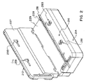
図2を参照すると、図1のポンプ210は、開放位置であることが分かる。ポンプ210の本体部分214内には、少なくとも1個の流体送達機構216が設置されている。流体送達機構216は、チューブ装填チャンネル228を備え、その中には、チューブ28がポンプ210に装填される。流体送達機構216は、チューブ装填特性をさらに備える。流体送達機構216には、底板229が付随している。カバー212には、上板227が付随している。底板229上には、受容機構281、283が配置されている。上板227上には、受容機構281、283と操作可能に付随して、掛け金機構291、293が配置されている。
【0186】
今ここで、図3を参照すると、図1のポンプ210の分解図が描写されている。ポンプ210は、さらに、カバー212上に配置されたパッド216を備え、パッド216は、ポンプ210へのキーパッド(keypad)アクセスを与える。パッド216には、ディスプレイ217用の窓が設けられている。好ましい実施態様では、ディスプレイ217は、LCDディスプレイであり得る。ポンプ210は、ポンプ210の操作を制御するための電子制御装置230を備える。ポンプ210内には、オクルダー機構240が配置され、オクルダー機構240は、以下で詳細に記述するように、チューブ228を通って流体を移動させる手段を提供する。ポンプ210には、電源232もまた配置されており、電源232は、ポンプ210を操作する出力源を供給する。本明細書中で記述される好ましい着装携行式実施態様では、電源232は、一連の電池である。オクルダー機構240には、ソレノイド弁242、243、244および245が備えられている。ソレノイド弁242、243、244および245の機能は、以下でさらに詳細に記述する。
【0187】
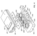
図4を参照すると、これは、ポンプ210の内部にある部品を図示しているポンプ210の分解図である。ポンプ210は、オクルダー252、262およびプランジャー272、273をさらに備える。オクルダー252、262およびプランジャー272、273の機能は、以下でさらに詳細に記述する。
【0188】
今ここで、図5を参照すると、本発明の原理に従って作製された流体送達機構の概略図が示される。可撓性流体容器23が設けられ、これは、液体で満たされて、チューブ28に接続されている。流体容器23は、この流体送達装置(図示せず)にあるチャンバーに装填される。1実施態様では、容器23は、必要に応じて、固定板22と膨張可能ブラダー24との間に配置され得る。膨張可能ブラダー24の外側には、拘束手段26が設けられている。拘束手段26の目的は、ブラダー24が膨張時に容器23を押すように、ブラダー24の膨張を制限することにある。ブラダー24は、流体作動チャンバであり得る。
【0189】
この流体送達装置にチューブ28が装填されるとき、チューブ28の一部分は、第一固定板75とプランジャー73との間で、予め圧縮されている。チューブ28は、非閉塞位置まで予め圧縮される。2個のオクルダー152、162は、チューブ28を挟んで締め付けるプランジャー73の各側面に1個ずつ備え付けられている。オクルダー152、162間には、計量チャンバが配置されている。プランジャー73の流体容器23側に位置しているオクルダーは、上流オクルダー152と呼ばれ、もう一方のオクルダーは、下流オクルダー162と呼ばれる。
【0190】
チューブ28を予め圧縮した結果、圧縮しないときの円形チューブの断面形状に対して、ほぼ楕円形の断面形状が得られる。このチューブを予め圧縮すると、また、このチューブが部分的に減圧される。このチューブをほぼ楕円形の断面形状に予め圧縮することにより、プランジャー73の1単位ストローク距離あたりで送達できる薬物適用量一回分の容量は、予め圧縮しないときに送達できる薬物適用量一回分の容量よりも多くなる。さらに、このチューブを予め圧縮すると、このチューブは、予め応力をかけられた状態で維持されて、それにより、このプランジャーによるこのチューブのそれ以上の圧縮を解除した後、このチューブが予め圧縮されていたために受けた形状に戻る力が与えられる。それに加えて、このチューブを予め圧縮すると、その液体源に向かう方向でチューブを通って液体の流れが生じている間にて、チューブが伸長し過ぎるのを防止する。この予備圧縮の局面の各々は、以下でさらに詳細に説明する。
【0191】
達成できる最大の薬物適用量一回分の容量は、以下の等式により、記述され得る:
Vb=(Vd/T)/(Nc/T)
=Vd/Nc;ここで、
Vb=薬物適用量一回分の容量;
Vd=最低の流速で送達される容量;
T=薬物適用量一回分の容量が送達される時間;そして
Nc=送達サイクル数。
【0192】
この予備圧縮の結果として、このチューブが受ける曲げ半径は、チューブの壁厚に等しいかまたはそれより大きくすべきであることが、一般に、望ましい。これは、この予備圧縮中にこのチューブが受ける応力(これは、チューブの曲げの低下を引き起こし得る)を最小にするためにある。この半径限度を適用すると、このプランジャーの最大ストローク距離は、以下のように定義される:
Stmax=IDmin−2Wmax;ここで、
Stmax=最大ストローク距離;
IDmin=チューブの最小内径;そして
Wmax=チューブの最大壁厚。
【0193】
理論的な薬物適用量一回分の容量は、チューブの直径が薬物適用量一回分の容量を送達する間に変化するので、この上流オクルダーと下流オクルダーとの間にあるチューブの長さおよびチューブの直径の関数として、定義できる。従って、この薬物適用量一回分の容量は、以下のようにして、定義され得る:
Vb=Vo−Vr;ここで、
Vb=薬物適用量一回分の容量;
Vo=チューブの初期容量;
Vr=薬物適用量一回分の容量を送達した後、チューブ中に残留している流体の容量。
Vrは、以下のようにして、計算され得る:
Vr=Va+Vf;ここで、
Va=円弧直径Daを有する楕円弧の容量;
Va=πPL(Da/2)2
=πPL[(Da/2)(Da/2)]
=πPL(Da 2/4);ここで
PL=プランジャーの長さ;
Vf=長さLfを有する楕円平坦部分の容量、
Vf=DaLfPL;ここで、
Da=ID−St;ここで、
ID=チューブの内径;そして
St=プランジャーのストローク距離;
Lf=(Ci−La)/2
=[(πID)−(πDa)]/2
=[πID−π(ID−St)]/2
=(πSt)/2;ここで、
Ci=チューブの内周;
Va=πPL(Da/2)2
=πPL[(ID−St)/2]2
=πPL{[(ID−St)(ID−St)]/4}
=πPL{[ID2−2IDSt+St 2]/4};
Vf=DaLfPL
=PL[(ID−St)(πSt)/2]
=πPL[(ID−St)(St/2)]
=πPL[(IDSt−St 2)/2]
=πPL[(2IDSt−2St 2)/4];
Vr=Va+Vf
=πPL{[ID2−2IDSt+St 2]/4}+πPL{(2IDSt −2St2)/4}
=πPL{[(ID2−2IDSt+St 2)+(2IDSt−2St 2)] /4}。
上で展開した項を組み合わせると、以下が得られる:
Vb=Vo−Vr
=πPL[ID2/4]−πPL{[ID2−St 2]/4}
=πPL{[ID2/4]−[(ID2−St 2)/4]}
=πPL[ID2−ID2−St 2]/4]
=πPLSt 2/4
それゆえ、この予備圧縮(それによって、このチューブは、ほぼ楕円形を呈する)があるために、その薬物適用量一回分の容量は、チューブの内径の大きさには依存しないことが分かる。また、このチューブの形状が円形から楕円形へと変わるので、この薬物適用量一回分の容量は、このプランジャーストローク距離に対して、直線的には変化しない。
【0194】
プランジャー73がチューブ28を押すとき、一定ストローク距離に対して、送達される薬物適用量一回分の容量は、プランジャー73ストロークの開始時に楕円形チューブ28が使用される場合と比較して、円形チューブで開始するときには、少なくなる。しかし、このストローク距離は固定されているので、このプランジャーがこのストローク距離にわたって移動する際に消費されるエネルギーは、その出発チューブ形状には関係なく、同じになる。従って、チューブ28を予め圧縮した結果、一定の薬物適用量一回分の容量に対して、チューブ28を通って流体を押す際のエネルギー消費が少なくなる。プランジャー73がチューブ28を押し付けるのを中止するとき、プランジャー73は、チューブ28の予備圧縮が回復されるように、引き出される。従って、チューブ28は、第二の非弛緩位置(non−relaxed position)まで除圧される。
【0195】
図6〜13は、本発明の原理に従って製造されたオクルダー機構40の実施態様を描写している。図6は、オクルダー機構40の平面断面図である。図7は、オクルダー機構40の立面断面図である。
【0196】
上流オクルダー152および下流オクルダー162は、共に、オクルダー152、162を閉鎖位置へと偏らせるように、バネ装填されている。プランジャー73は、プランジャー73を開放位置へと偏らせるように、バネ装填されている。オクルダー152、162およびプランジャー73は、それぞれ、空気シリンダーに接続されており、これらは、圧縮空気により操作され、そして制御装置(図示せず)により制御される。オクルダー152、162に付随した各空気シリンダーは、好ましくは、三方ソレノイド弁43、45により制御され、そしてプランジャー73に付随した空気シリンダーは、好ましくは、ソレノイド弁42により制御される。この空気式設計とオクルダー機構40の制御操作手順とに依存して、プランジャー73に付随した空気シリンダーを制御するために、2個のソレノイド弁42、44が使用され得る。
【0197】
チューブ28が開いて送達準備が完了したことを確認するために、下流オクルダー162は、プランジャー73が閉鎖位置の方へと移動する前に、開かれる。逆流を防止するために、下流オクルダー162はまた、プランジャー73が開放位置に戻る前に、閉じられる。上流オクルダー152は、この下流オクルダー開放期間中にて、開かれない。この一連の操作方法は、その流体の自由流れ(free−flow)を防止するために、設計されている。
【0198】
上流および下流オクルダー152、162は、機械弁であり、これらは、容器23と、この計量チャンバと、このチューブ28の遠位末端との間で、流体通路を開閉する。上流および下流オクルダー152、162により、また、液体を、この計量チャンバに満たし、そして液体の自由流れまたは逆流なしに、計量チャンバから逃げることができる。
【0199】
上流および下流オクルダー152、162は、通常、閉じられている。上流および下流オクルダー152、162は、予め装填したバネにより発生する約2.5ポンド(好ましくは)の力により、チューブ28を挟んで締め付ける。上流および下流オクルダー152、162の両方は、この予備装填バネ力が調節できるように、設計されている。この予備装填バネ力は、オクルダー152、162がチューブ28を挟んで締め付けることができるのに充分であるべきである。
【0200】
プランジャー73は、チューブ28に圧力を加える可動板として、設計されている。このプランジャーは、好ましくは、アルミニウムから製造されるが、他の材料、金属およびプラスチックの両方が、適切な構造材料である。板75は、必要に応じて、プランジャー73を操作可能に受容するチャンネルの形状で、構成されている。板75およびプランジャー73は、オクルダー機構40内に位置づけられる。
【0201】
同様に、オクルダー機構40は、アルミニウムまたは他の適切な材料から構成できる。オクルダー機構40は、上流および下流オクルダー152、162およびプランジャー73の操作用に組み込んだ3個の空気シリンダーと共に、構成されている。上流および下流オクルダー152、162に付随した空気シリンダーの各々は、インラインソレノイド弁に直接的に接続されている。プランジャー73は、少なくとも1個のインラインソレノイド弁に接続されている。
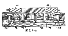
【0202】
図8は、図6のA−A軸に沿って取り出したオクルダー機構40の立面断面図を示す。上流オクルダー152は、閉鎖位置で示され、そしてプランジャー73も同様に、閉鎖位置で示されている。下流オクルダー162およびプランジャー73は、共に、開放位置で示されている。プランジャー73と操作可能に付随しているソレノイド弁42の位置が示されている。
【0203】
図9は、図6のB−B軸に沿って取り出した立面断面図である。ソレノイド弁42とプランジャー73との間の入口空気接続部47が図示されている。
【0204】
図10は、図6のC−C軸に沿って取り出した立面断面図である。ソレノイド弁43およびソレノイド弁45から、それぞれ、上流オクルダー152および下流オクルダー162までのこの空気接続部の位置が示される。
【0205】
図11は、図6のD−D軸に沿って取り出した立面断面図である。ソレノイド弁42とプランジャー73との間の出口空気接続部82が図示されている。
【0206】
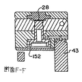
図12および13は、それぞれ、下流および上流オクルダー162、152の立面断面図を図示している。図12は、図6のE−E軸に沿って取り出した断面であるのに対して、図13は、図6のF−F軸に沿って取り出した断面である。図12では、この上流オクルダーは、チューブ28を挟んで締め付けている閉鎖位置に示される。図13では、下流オクルダー162は、開放位置で示されている。
【0207】
1実施態様では、オクルダー機構40およびブラダー24に全空気圧を加えるために、通常市販の空気圧縮機が使用される。代わりに、ブラダー24に空気圧を加えるために、1つの空気圧縮機が使用され、そしてオクルダー機構40に空気圧を加えるために、第二の空気圧縮機が使用され得る。複数の空気圧縮機もまた、使用され得る。
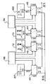
【0208】
今ここで、図14を参照すると、本発明の原理に従ったシステムの図が示されている。このシステムは、流体圧縮機39を利用する。電源32は、弁制御装置35に出力を供給する。弁制御装置35は、ブラダー制御弁31を制御する。ブラダー制御弁31は、ブラダー24に圧縮空気を供給し、これは、順に、容器23を押し付けて、圧縮液体源を作製する。
【0209】
電源32はまた、制御装置33および圧縮機39に出力を供給する。制御装置33は、圧縮機39(これは、エネルギー保存タンク37で保存される流体圧力を発生するのに使用される)を制御する。エネルギー保存タンク37により、圧縮機39の断続的な操作が可能となり、それにより、電源32を維持する。好ましい実施態様では、この流体は、空気である。制御装置33はまた、任意のソレノイドスパイクおよびホールド回路36を制御する。このソレノイドスパイクおよびホールド回路36は、オクルダー機構40を制御するソレノイドを制御する。このスパイクおよびホールド回路36がない場合、制御装置33は、オクルダー機構40を直接的に制御する。制御装置33は、このソレノイドスパイクおよびホールド回路36を制御する。圧縮した空気は、エネルギー保存タンク37から、オクルダー機構40(これは、上流オクルダー152および下流オクルダー162、プランジャー73、およびブラダー24を備える)へと分配される。これらのソレノイド弁の操作は、さらに、以下で記述する。
【0210】
エネルギー保存タンク37は、好ましくは、約0.3175cm(0.125インチ)厚の溶接アルミニウムから構成され、これは、約315cm3(19.2立方インチ)の容量を有する。しかしながら、他の材料および構成方法および他のサイズが、使用され得る。エネルギー保存タンク37は、ブラダー24、上流および下流オクルダー152、162ならびにプランジャー73を操作するのに必要な空気圧を安全に含むように、構成されなければならない。その圧力は、約1psig(ゲージ圧)〜約50psig、および好ましくは、約3psig〜約15psigの範囲であり得る。エネルギー保存タンク37のサイズおよびこの空気圧は、この空気圧縮機の運転時間を最小にするように、従って、エネルギーを保存するように選択できる。上流および下流オクルダー152、162は、好ましくは、約9psig(約7psig〜約11psigの範囲)の空気圧下にて作動するのに対して、ブラダー24は、好ましくは、約3psig(約2psig〜約4psigの範囲)の空気圧下にて作動する。
【0211】
エネルギー保存タンク37内の圧力が、最小設定値(これは、制御装置33の一部をなす圧力変換器(図示せず)により、決定される)より低下するにつれて、制御装置33は、空気圧縮機39を起動して、エネルギー保存タンク37を再充填し、エネルギー保存タンク37内の空気圧を、第二圧力変換器により決定される最大圧力へと高める。これらの圧力変換器の設定値により規定される圧力範囲は、操作圧力エンベロープと呼ばれる。
【0212】
ブラダー24内の圧力は、圧力変換器によりモニターされ、そして制御装置33により制御される。ブラダー24内の空気圧は、最終的には、流体容器23に加えられる。容器23内の圧力は、チューブ28に加えられる。流体容器23から流体が逃げるにつれて、ブラダー24内の圧力は、変換器により決定されるさらに低い圧力設定値まで低下する。その値では、制御装置33は、ソレノイド弁を起動して、圧縮空気をブラダー24内へと流し、それにより、この圧力変換器により決定される上方圧力設定値に達するまで、ブラダー24内の空気圧を高める。次いで、制御装置33は、このソレノイド弁を再起動して、エネルギー保存タンク37とブラダー24との間の圧力を遮断し分離する。
【0213】
これらのソレノイド弁は、例えば、PACKER CORPORATIONから入手できる。これらのソレノイド弁は、好ましくは、約1ボルト〜12ボルトDCの動作電圧、約50ミリワット〜約1000ミリワットの電力消費量、および約1ミリ秒〜約1000ミリ秒の応答時間を有する。ソレノイド弁を通る流速は、約0.25mL/分(6.6×10−5ガロン/分)〜約1000mL/分(0.26ガロン/分)である。このブラダー内の圧力を制御するのに使用されるソレノイド弁は、4ボルトDCの動作電圧および約500ミリワットの電力消費量を有する。
【0214】
制御装置33に含まれるマイクロプロセッサ36は、複数の独立プログラムを備える。マイクロプロセッサ36はまた、複数のマイクロプロセッサを備え得る。あるプログラムは、ブラダー24を制御し、そして他のプログラムは、オクルダー機構40を制御する。ブラダー24が膨張する程、ブラダー24は、エネルギーを容器23に非効率的に移動させることが公知である。従って、このマイクロプロセッサに含まれるプログラムは、ブラダー24の圧力設定値が、各再充填サイクルにて、一定圧力まで高められるように、設計される。この圧力増分は、ブラダー効率補償圧力または調整圧力と呼ばれている。理想的には、ブラダー24内の圧力は、容器23の漏れまたは破裂およびチューブ28の内部膨張を防止するために、できるだけ低いが、容器23から液体を押し出すのに充分に高い。このプログラムはまた、エネルギー保存タンク37内の圧力およびブラダー24内の圧力を定期的に検査する。
【0215】
オクルダー機構40を操作するのに使用されるプログラムは、以下の3つの主要な機能を果たす:ユーザーインターフェイス、操作圧力の制御、および操作時間の制御。Munichおよび当該技術分野で公知の他の調整圧力サブルーチンは、ブラダー24を制御するのに使用されるプログラムに含まれる。ブラダー24が伸長するにつれて(この伸長は、累積的な圧縮機39の活動を感知することにより、決定される)、最大圧力設定値は、上方へと偏る。この累積圧力制御方法により、ブラダー24を通るエネルギー移動の非効率性が減少する;従って、この計量チャンバは、一貫して満たされ、一貫した薬物適用量一回分の容量を生じて、流速精度をさらに高くする。
【0216】
この流体送達装置のスイッチが、電源スイッチを起動することにより、オンにされると、ブラダー24を制御するプログラムは、自己試験を実行する。この自己試験を首尾良く完了すると、このプログラムは、ブラダー24の加圧を開始し、この流体送達装置の空気部品での漏れについて検査を開始し、そしてオクルダー152、162およびプランジャー73の位置を検査する。この漏れ試験は、完了するのに約30秒かかる;この間、もし、液体が容器23から逃げ得るなら、この漏れ試験は失敗し、警報が鳴らされ得る。もし、漏れが見つからないなら、このプログラムは、高低(low−high)ブザーを鳴らすことにより、準備完了信号を表示する。次に、このプログラムは、好ましくは、パスワードの形式で、ユーザーインターフェイス38から、ユーザー入力を検査する。この電源のスイッチをオンにした時点から、このプログラムは、もし、パスワードが認められないなら、上記手順を定期的に起動する。もし、この手順中にて、その空気圧がいずれかの設定値より低下するなら、このマイクロプロセッサは、空気圧縮機39を作動させる。追加のプログラムは、使用され得る。
【0217】
ユーザーインターフェイス38は、以下の3つの機能を含む:プログラミングパネル、LCDディスプレイおよびIR連絡ポート。このプログラミングパネルは、キーパッドを備え、これは、例えば、この流速、薬物適用量一回分の容量、用量数、注入する容量、送達時間、この流体送達装置の状態、ならびに/または上流および下流オクルダー152、162に加える圧力をプログラムするのに、使用される。このキーパッドはまた、オクルダー機構40に対する操作手順をプログラムするのに、使用され得る。各キーを押すと、ビーッという短い音によって確認される。注入される容量は、薬物適用量一回分の容量のリストから選択され得、これには、例えば、5mL(0.00132ガロン)、10mL(0.00264ガロン)、50mL(0.0132ガロン)、100mL(0.0264ガロン)、250mL(0.066ガロン)、300mL(0.079ガロン)および999mL(0.264ガロン)が挙げられる。好ましくは、流速は、流速リストから選択され得、これには、例えば、0.5mL/hr(0.000132ガロン/hr)、1mL/hr(0.000264ガロン/hr)、2mL/hr(0.000528ガロン/hr)、3mL/hr(0.000793ガロン/hr)、4mL/hr(0.00106ガロン/hr)、5mL/hr(0.00132ガロン/hr)、10mL/hr(0.00264ガロン/hr)、20mL/hr(0.00528ガロン/hr)、50mL/hr(0.0132ガロン/hr)、100mL/hr(0.0264ガロン/hr)および200mL/hr(0.0528ガロン/hr)が挙げられる。この流体送達装置の状態は、スイッチによってアドレス可能(addressable)であり、これは、この流体送達装置を始動および/または停止するのに、使用される。このスイッチを起動すると、マイクロプロセッサ36は、ユーザーインターフェイス38から受信されたプログラム化パラメータに基づいて注入を開始し、そしてIR連絡ポートによって入力された時間サイクルに従って、操作される。このスイッチは再度押すと、この流体送達を停止する。メニュースイッチもまた、設けることができ、これにより、流体送達の状態を予告できる。
【0218】
上流および下流オクルダー152、162に加えられる圧力は、負荷スイッチによってアドレス可能であり、このスイッチは、それぞれ、プランジャー73のソレノイド弁42、44の通気(venting)を手動で起動させ、そしてソレノイド弁43、45(これらは、それぞれ、上流および下流オクルダー152、162を制御する)を、両方とも、加圧する。この機能は、チューブ28のオクルダー機構40へのより簡単な装填を提供するために、設計されている。
【0219】
このLCDディスプレイは、この流体送達のプログラム化パラメータの視覚的な出力を供給する。例えば、注入ポンプとして使用するとき、このLCDは、薬物適用量一回分の容量、流速および状態を表示し、また、患者に送達される液体の現在の蓄積容量を表示する。この現在の蓄積容量は、薬物適用量一回分の容量が患者に送達される回数に基づいて、決定される。
【0220】
このIR連絡ポートは、この流体送達装置の操作パラメータ(これには、薬物適用量一回分の容量の送達のタイミング、薬物適用量一回分の容量、および操作圧力パラメータが挙げられる)を検査および/または変更する。プログラムは、この流体送達装置のスイッチをオンにしたとき、またはユーザーがユーザーインターフェイス38によってこのような表示を必要とするときはいつでも、その現在の設定と共に、パラメータのメニューを表示する。これらの操作パラメータは、消去可能でプログラム化可能な読み出し専用メモリー(EPROM)で保持され、行われるいずれの変更も、持続する。
【0221】
このオクルダー機構プログラムはまた、空気圧縮機39(これは、エネルギー保存タンク37に圧縮空気を供給する)を制御する;エネルギー保存タンク37からの圧縮空気は、上流および下流オクルダー152、162およびプランジャー73を操作するのに使用される。圧力設定値および圧力エンベロープは、このIR連絡ポートにより、調節できる。エネルギー保存タンク37内の圧力は、この圧力が最小値(これは、オクルダー機構40の部品の操作圧力要件に基づいて、定義できる)より高く保持される限り、オクルダー機構40の性能に対して、重要ではない。
【0222】
このオクルダー機構プログラムはまた、ソレノイド弁42、43、44、45のタイミングおよび液体の送達のタイミングを制御する。ソレノイド弁のタイミングの制御プログラムは、上流および下流オクルダー152、162およびプランジャー73を操作するのに、使用される。
【0223】
予定したタイミング制御プログラムは、選択した流速および薬物適用量一回分のサイズに基づいている。この流速および薬物適用量一回分のサイズが、ユーザーインターフェイス38によって入力されるとき、このプログラムは、送達の予定時間を自動的に計算する。例えば、0.083mLの薬物適用量一回分のサイズを用いて100mL/hrの流速で送達するための時間スケジュールを見つけるために、まず、このプログラムは、この薬物適用量一回分のサイズが、この送達の全体にわたって不変であると仮定する。1薬物適用量一回分あたり0.083mLで100mLを送達するためには、1204.8回の送達サイクルが必要である;オクルダー機構40を1204.8サイクル/時間(すなわち、3600秒)で操作するためには、オクルダー機構40は、2.988秒以内に、1サイクルを実行する。従って、この送達時間スケジュールが計算できる。
【0224】
図15を参照すると、オクルダー機構40で使用するために、単一のプランジャーと共に、3個のソレノイド弁を利用する配置の概略図が示されている。ソレノイド弁43は、上流オクルダー152を制御するのに使用され、ソレノイド弁45は、下流オクルダー162を制御するのに使用され、そしてソレノイド弁42は、プランジャー73を制御するのに使用される。
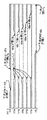
【0225】
今ここで、図16を参照すると、図15の配置を利用するオクルダー機構40の操作プロフィールが提示されている。ソレノイド弁45には電圧が加えられ、通常閉じた共通ポートが接続されて、空気圧が下流オクルダー162の空気シリンダーに入るようにされ、それにより、予備装填バネ力に対抗して押して、下流オクルダー162を開く。この作用により、液体は、プランジャー73がチューブ28を押したとき、この計量チャンバから逃げることができる。下流オクルダー162は、プランジャー73の前方移動中にて、プランジャー73が時間(m)の間に最大ストロークに達するまで、開いたままになる(ソレノイド弁45には、電圧をかけたままである)。時間(m)の後、ソレノイド弁45の電圧が断たれ、通常開いた共通ポートが接続されて、下流オクルダー162の空気シリンダーを通気する。この時点で、予備装填バネは、力を加えて、下流オクルダー162にて、チューブ28を挟んで締め付ける。
【0226】
下流オクルダー162を時間(c)にわたって開いた後、ソレノイド弁46には電圧が加えられ、通常閉じた共通ポートが接続されて、空気圧がプランジャー73の空気シリンダーに入るようにされ、それにより、予備装填バネ力に対抗して押して、時間(d)にわたって、プランジャー73を前方に起動する。時間(d〜e)は、プランジャー73の空気シリンダーの内側で充分な圧力が蓄積されるように、ソレノイド弁42に対して充分な開放時間を与えるように設計される。次いで、ソレノイド弁42の電圧が断たれ、プランジャー73の空気シリンダーを通気して、プランジャー73をその初期位置に戻す。これらの時間関数は、段階関数として示されているものの、非線形時間関数は、可能である。
【0227】
ソレノイド45の電圧を時間(f)にわたって断った後、ソレノイド43には電圧が加えられ、通常閉じた共通ポートが接続されて、空気圧が上流オクルダー152の空気シリンダーに入るようにされ、それにより、予備装填バネ力に対抗して押して、上流オクルダー152を開く。この作用により、液体は、上流オクルダー152を通って、その流体源に戻って逃げ、それにより、フラッシュバックして、これは、順に、上流オクルダー152により形成されたチューブ28の締め付け領域(pinched−off area)を再び開く。
【0228】
このフラッシュバックサイクルの後、上流オクルダー152が依然として開いている間、両方のソレノイド弁42の電圧が断たれる。通常開いた共通ポートが接続されて、空気が、プランジャー73の空気シリンダーから通気される。この時点で、プランジャー73の予備装填バネは、力を加えて、プランジャー73を押し開き、それにより、チューブ28を解放し、そして吸引力を作り出して、この液体を容器23から引き出し、この計量チャンバを満たす。
【0229】
時間(a/h)の後、ソレノイド43の電圧が断たれ、通常開いた共通ポートが接続されて、上流オクルダー152の空気シリンダーが通気される。この時点で、上流オクルダー152の予備装填バネは、力を加えて、上流オクルダー152にて、チューブ28を挟んで締め付け、制御装置33は、次の送達サイクルを実行するための始動(waking−up)前に、残りの予定時間にわたって、待機モードに切り替わる。もう一度、上記作業および手順の全ては、予定時間(T)(これは、一定流速および所定薬物適用量一回分の容量での送達サイクルの周期に相当する)内で、操作される。
【0230】
図17を参照すると、オクルダー機構40で使用するために、4個のソレノイド弁を利用する配置の概略図が示されている。ソレノイド弁43は、上流オクルダー152を制御するのに使用され、ソレノイド弁45は、下流オクルダー162を制御するのに使用され、ソレノイド弁42は、プランジャー73の前方移動を制御するのに使用され、そしてソレノイド弁44は、プランジャー73を通気するのに使用される。
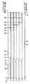
【0231】
図18を参照すると、4個のソレノイド弁を利用するオクルダー機構40の操作プロフィールが提供されている。ソレノイド弁45に電圧を加えると、通常閉じた共通ポートが接続されて、空気圧が下流オクルダー162の空気シリンダーに入るようにされ、それにより、予備装填バネ力に対抗して押して、下流オクルダー162を開く。これにより、液体は、プランジャー73をチューブ28に押したとき、チューブ28から逃げることができる。下流オクルダー162は、時間(c+d+e)にわたって、プランジャー73が移動してチューブ28を圧縮するとき、開いたままになる。
【0232】
下流オクルダー162を開いた後、ソレノイド弁42には電圧が加えられ、通常閉じた共通ポートが接続されて、空気圧がプランジャー73の空気シリンダーに入るようにされ、それにより、予備装填バネ力に対抗して押して、時間(d)にわたって、このプランジャーを前方に起動する。時間(d〜e)は、プランジャー73の空気シリンダーの内側で充分な空気圧が蓄積されるように、ソレノイド弁42に充分な開放時間を与えるように設計される。次いで、ソレノイド弁42の電圧が断たれる。この時点で、プランジャー73は、そのストロークの終点に達し、その前方位置でとどまる。
【0233】
ソレノイド弁42の電圧を時間(e)にわたって断った後、ソレノイド弁45の電圧が断たれ、通常開いた共通ポートが接続されて、下流オクルダー162に付随した空気シリンダーが通気される。この時点で、下流オクルダー162の予備装填バネは、下流オクルダー162にて、力を加えて、チューブ28を挟んで締め付ける。時間(e)は、下流オクルダー162が開放位置にある時間量を規定する変数として、設計される;この変数は、もし、下流オクルダー162が開放位置にある時間値が確立されれば、なくすことができる。
【0234】
ソレノイド弁45の電圧を時間(f)にわたって断った後、ソレノイド弁43には電圧が加えられ、通常閉じた共通ポートが接続されて、空気圧が上流オクルダー152の空気シリンダーに入るようにされ、それにより、予備装填バネ力に対抗して押して、上流オクルダー152を開く。この作用により、液体は、プランジャー73が開放位置に戻るとき、この計量チャンバを満たす。上流オクルダー152は、一定時間にわたって開いたままになり、液体がこの計量チャンバを完全に満たすのを保証する。時間(f)は、下流オクルダー162が上流オクルダー152の開放前に閉じられることを保証するように、設計されている。
【0235】
ソレノイド弁43に電圧を加えるのと同時に、ソレノイド弁44にも電圧が加えられ、通常閉じた共通ポートが接続されて、空気が、プランジャー73の空気シリンダーから通気される。この時点で、プランジャー73の予備装填バネは、プランジャー73を開放位置まで押し戻して、チューブ28を解放し、そして吸引力を作り出して、液体を容器23から引き出し、この計量チャンバを満たす。上流オクルダー152は、一定時間にわたって開いたままになり、液体がこの計量チャンバを完全に満たすのを保証する。
【0236】
図17および18で描写した流体送達装置の実施態様では、流体フラッシュバック操作が可能である。この流体フラッシュバック操作では、流体は、チューブ28を通って、この流体源の方へと押し戻される。このようにして、このフラッシュバック力は、そうしないと圧潰されるチューブ28を再び開くのに使用できる。このフラッシュバックは、チューブ28内にいくらか流体がある限り、機能する。
【0237】
今ここで、図19を参照すると、本発明の原理に従って作製された流体送達機構の代替実施態様の概略図が示され、ここで、二重プランジャー配置が利用される。図5〜18で描写した関連実施態様の記述と一致して、なるべく、同じ番号は、同じ要素を示すのに使用される。チューブ28が、この流体送達装置に装填されるとき、チューブ28の一部分は、第一固定板75と第一プランジャー72との間で、予め圧縮されているのに対して、チューブ28の別の部分は、第二固定板76と第二プランジャー73との間で、予め圧縮されている。第一固定板75および第二固定板76は、1つの連続した板の一部であり得る。2個のオクルダー152、162は、チューブ28を挟んで締め付けるために、プランジャー72、73の各側で1個ずつ設けられている。2個のオクルダー152、162間には、計量チャンバが配置されている。
【0238】
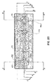
図20〜25は、図19のオクルダー機構40の代替実施態様を描写する。図20は、オクルダー機構40の平面断面図である。図21は、オクルダー機構40の立面断面図である。
【0239】
上流オクルダー152および下流オクルダー162は、共に、閉鎖位置へとバネ装填されている。プランジャー72、73の両方は、開放位置へとバネ装填されている。オクルダー152、162およびプランジャー72、73は、それぞれ、空気シリンダーに接続されており、これらは、圧縮空気により操作される。オクルダー152、162に付随した各空気シリンダーは、好ましくは、三方ソレノイド弁43、45により制御され、そしてプランジャー72、73に付随した2個の空気シリンダーは、好ましくは、それぞれ、ソレノイド弁42、44により制御される。制御装置33は、マイクロプロセッサ36を備え、ソレノイド弁42、43、44、45の操作を制御する。マイクロプロセッサ36は、複数のマイクロプロセッサを備え得る。本実施態様での制御装置33およびマイクロプロセッサ36の機能および操作は、上記のようなこれらの部品の機能および操作と類似している。
【0240】
必要に応じて、プランジャー72、73のストローク距離を制御し易くするために、圧力変換器(図示せず)が使用され得る。この圧力変換器に付随して、プランジャー72、73の各々には、追加ソレノイド弁(図示せず)が設けられている。この追加ソレノイドは、これらの空気シリンダーからの空気の通気を開閉する性能を備えている。この圧力変換器は、これらの空気シリンダーの各々での圧力に比例した出力信号を提供する。この出力信号は、制御装置33により感知される。制御装置33は、各プランジャーに付随したソレノイド弁42、44および追加ソレノイド弁の開閉を制御する。それゆえ、ソレノイド弁42、44および追加ソレノイド弁は、これらの空気シリンダーを圧力を高めて加圧するかまたは通気して、それにより、プランジャー72、73のストロークを制御するために、開閉できる。
【0241】
チューブ28が開いて送達準備が完了したことを保証するために、下流オクルダー162は、プランジャー72、73が閉鎖位置の方へと移動する前に、開かれる。逆流を防止するために、下流オクルダー162はまた、プランジャー72、73が開放位置に戻る前に、閉じられる。上流オクルダー152は、この下流オクルダー開放期間中にて、開かれない。この一連の操作方法は、その液体の自由流れを防止するために、設計されている。
【0242】
上流および下流オクルダー152、162は、上記のように、機械弁である。本実施態様におけるオクルダー152、162に提供される設計、製造および機能は、上の記述と一致している。プランジャー72、73は、上記のように、チューブ28に圧力を加える可動板として、設計されている。従って、本実施態様におけるプランジャー72、73に提供される設計、製造および機能は、上の記述と一致している。
【0243】
オクルダー機構40は、上流および下流オクルダー152、162およびプランジャー72、73の操作用に組み込まれた4個の空気シリンダーと共に、構成されている。上流および下流オクルダー152、162に付随した空気シリンダーの各々は、インラインソレノイド弁に直接的に接続されている。プランジャー72、73は、それぞれ、少なくとも1個のインラインソレノイド弁に接続されている。
【0244】
図22は、図20のA−A軸に沿って取り出したオクルダー機構40の立面断面図を示す。上流オクルダー152は、閉鎖位置で示され、そしてプランジャー72も同様に、閉鎖位置で示されている。下流オクルダー162およびプランジャー73は、共に、開放位置で示されている。プランジャー72と操作可能に付随しているソレノイド弁42の位置が示されている。同様に、プランジャー73と操作可能に付随しているソレノイド弁44の位置が示されている。
【0245】
図23は、図20のB−B軸に沿って取り出した立面断面図である。ソレノイド弁42とプランジャー72との間の入口空気接続部47が図示されている。同様に、ソレノイド弁44とプランジャー73との間の入口空気接続部49が図示されている。
【0246】
図24は、図20のC−C軸に沿って取り出した立面断面図である。ソレノイド弁43およびソレノイド弁45から、それぞれ、上流オクルダー152および下流オクルダー162までのこの空気接続部の位置が示される。
【0247】
図25は、図20のD−D軸に沿って取り出した立面断面図である。ソレノイド弁42とプランジャー72との間の出口空気接続部82が図示されている。同様に、ソレノイド弁44とプランジャー73との間の出口空気接続部84が図示されている。出口82、84は、それぞれ、プランジャー72、73の各々に付随した空気シリンダーを通気する。
【0248】
上流および下流オクルダー152、162の断面図は、それぞれ、図12および13で示した図と類似している。それゆえ、図20の断面E−Eに沿った図は、図12で示したものと同じ外観を有する。同様に、図20の断面F−Fに沿った図は、図13で示したものと同じ外観を有する。
【0249】
図26を参照すると、このオクルダー機構で使用するために、4個のソレノイド弁を利用する二重プランジャー配置の概略図が示されている。ソレノイド弁43は、上流オクルダー152を制御するのに使用され、ソレノイド弁45は、下流オクルダー162を制御するのに使用され、ソレノイド弁42は、プランジャー72を制御するのに使用され、そしてソレノイド弁44は、プランジャー73を制御するのに使用される。この二重プランジャー配置は、以下の機能を与える:高い液体流速では、両方のプランジャー72、73は、より大きな薬物適用量一回分の容量を生じるために、並行して操作するようにプログラムされ得る;中程度の液体流速では、これらのプランジャーの1個(例えば、プランジャー72)が操作され得るのに対して、プランジャー73は、さらに安定した流れを生じるために、使用不能にされるか、または両方のプランジャー72、73は、エネルギーを節約するために、連続して作動するように、プログラム化できる;そして低い流速(この場合、上流オクルダー152は、長時間にわたって、チューブ28を挟んで締め付ける)では、プランジャー72、73は、フラッシュバック操作を実行するように、プログラム化され得る。チューブ28が、長時間にわたって、オクルダー152、162により挟んで締め付けられるとき、チューブ28は、流体がこの計量チャンバを再充填できるようには再び開き得ない。このフラッシュバック操作は、液体を、容器23の方へとチューブ28に押し戻し、それにより、開いた上流オクルダー152にて、チューブ28を開く。好ましい実施態様では、このフラッシュバック操作は、少なくとも2本のプランジャーを利用することにより、行われる。2本のプランジャーを使用することにより、チューブ28内には、フラッシュバックを与える流体が一部存在することが保証される。
【0250】
一般に、このフラッシュバック操作は、正確な薬物適用量一回分の容量が患者に注入されるように、チューブ28が、ほぼ、その初期直径に回復または再拡張する過程である。チューブ28が、長時間にわたって、下流オクルダー152によって挟んで締め付けられるとき、一旦、下流オクルダー152がその開放位置に移動すると、チューブ28は、ゆっくりとしか復元しない。引き続いて、この計量チャンバは、患者に薬物適用量一回分の容量を注入することを見越して、下流オクルダー152を閉じる前に、完全には満たされ得ない。不完全に計量チャンバに充填した結果、患者は、不正確な薬物適用量一回分の容量を注入される。この液体を流れ方向(これは、チューブ28を通って、この液体源の方へと戻る)に押すことにより、チューブ28を挟んで締め付けた場合、このチューブは、この計量チャンバが液体で満たされる前に、ほぼ、その初期直径まで再拡張され得る。これは、以下でさらに詳細に記述する。
【0251】
高い液体流速では、ソレノイド弁45には電圧が加えられ、通常閉じた共通ポートが接続されて、空気圧が下流オクルダー162の空気シリンダーに入るようにされ、それにより、予備装填バネ力に対抗して押して、下流オクルダー162を開く。この作用により、この液体は、プランジャー72または73のいずれかがチューブ28を押したとき、この計量チャンバから逃げることができる。
【0252】
今ここで、図27を参照すると、下流オクルダー162は、プランジャー72、73の前方移動中にて、プランジャー72、73が時間(m)の間に最大ストロークに達するまで、開いたままになる(ソレノイド弁45には、電圧をかけたままである)。この時間(m)の後、ソレノイド弁45の電圧が断たれ、通常開いた共通ポートが接続されて、下流オクルダー162の空気シリンダーを通気する。この時点で、予備装填バネは、その力を加えて、下流オクルダー162にて、チューブ28を挟んで締め付ける。
【0253】
下流オクルダー162を時間(c)にわたって開いた後、ソレノイド弁42には電圧が加えられ、通常閉じた共通ポートが接続されて、空気圧がプランジャー72の空気シリンダーに入るようにされ、それにより、予備装填バネ力に対抗して押して、時間(d)にわたって、プランジャー72を前方に起動する。この時間(d〜e)は、第一薬物適用量一回分を送達するためにプランジャー72の空気シリンダーの内側で充分な圧力が蓄積されるように、ソレノイド弁42に対して充分な開放時間を与える。次いで、下流オクルダー162が時間(n)にわたって開いた後、ソレノイド弁44に電圧が加えられ、通常閉じた共通ポートが接続されて、空気圧がプランジャー73の空気シリンダーに入るようにされ、それにより、予備装填バネ力に対抗して押して、時間(o)にわたって、プランジャー73を前方に起動する。この時間(o〜e)は、第二薬物適用量一回分を送達するために、プランジャー73の空気シリンダーの内側で充分な圧力が蓄積されるように、ソレノイド弁44に対して充分な開放時間を与える。これらの時間関数は、階段関数として示されているものの、非線形関数は、可能である。
【0254】
ソレノイド弁45の電圧を時間(f)にわたって断った後、ソレノイド43には電圧が加えられ、通常閉じた共通ポートが接続されて、空気圧が上流オクルダー152の空気シリンダーに入るようにされ、それにより、予備装填バネ力に対抗して押して、上流オクルダー152を開く。この作用により、液体は、プランジャー72、73が戻るとき、この計量チャンバを満たすことができる。上流オクルダー152は、時間(a/h)にわたって開かれて、液体がこの計量チャンバを完全に満たすのを保証する。時間(f)は、下流オクルダー162が上流オクルダー152の開放前に閉じられることを保証するように、設計されている。
【0255】
ソレノイド弁43に電圧を加えるのと同時に、ソレノイド弁42および44の電圧がまた断たれ、通常開いた共通ポートが接続されて、空気が、プランジャー72、73の空気シリンダーから通気される。この時点で、この予備装填バネは、プランジャー72、73をそれぞれ押し戻す力を加え、それにより、チューブ28を解放し、そして吸引力を作り出して、液体を容器23から引き出し、この計量チャンバを満たす。上流オクルダー152は、時間(a/h)にわたって開いたままになり、液体がこの計量チャンバを完全に満たすのを保証する。
【0256】
時間(a/h)の後、ソレノイド43の電圧が断たれ、通常開いた共通ポートが接続されて、上流オクルダー152の空気シリンダーが通気される。この時点で、上流オクルダー152の予備装填バネは、力を加えて、上流オクルダー152にて、チューブ28を挟んで締め付ける。制御装置33は、次の送達サイクルを実行するための始動前に、残りの予定時間にわたって、待機モードに切り替わる。
【0257】
上記作業および手順の全ては、予定時間(T)内で、操作される。予定時間(T)は、一定流速および所定薬物適用量一回分の容量での送達サイクルの周期に相当する。
【0258】
今ここで、図28を参照すると、中程度の送達流速範囲では、その操作プロフィールは、プランジャー73が使用不能にされているかまたはプランジャー72と一組で起動するようにプログラム化されていること以外は、高い流速のものと類似している。もし、プランジャー73が作動するようにプログラム化されるなら、時間(m)、(d)、(f)および(T)は、単一送達サイクル内で第二の薬物適用量一回分を受容するように、延長される。
【0259】
低い送達流速範囲では、送達サイクル間の予定時間は長いので、チューブ28は、上記のように、上流オクルダー152にて、挟んで締め付けられ変形される。締め付けられたチューブ28により、液体がこの計量チャンバを迅速に満たすのを防止できる。
【0260】
今ここで、図29を参照すると、低い送達流速範囲に対処するために、ソレノイド弁45には電圧が加えられ、通常閉じた共通ポートが接続されて、空気圧が下流オクルダー162の空気シリンダーに入るようにされ、それにより、予備装填バネ力に対抗して押して、下流オクルダー162を開く。この作用により、液体は、プランジャー72および/またはプランジャー73がチューブ28を押したとき、この計量チャンバから逃げることができる。下流オクルダー162は、プランジャー72、73の前方移動中にて、プランジャー72、73が時間(m)の間に最大ストロークに達するまで、開いたままになる(ソレノイド弁45には、電圧をかけたままである)。時間(m)の後、ソレノイド弁45の電圧が断たれ、通常開いた共通ポートが接続されて、下流オクルダー162の空気シリンダーを通気する。この時点で、予備装填バネは、力を加えて、下流オクルダー162にて、チューブ28を挟んで締め付ける。
【0261】
下流オクルダー162を時間(c)にわたって開いた後、ソレノイド弁42には電圧が加えられ、通常閉じた共通ポートが接続されて、空気圧がプランジャー72の空気シリンダーに入るようにされ、それにより、予備装填バネ力に対抗して押して、時間(d)にわたって、プランジャー72を前方に起動する。プランジャー72は、このフラッシュバックサイクルが完了するまで、その前方位置にとどまる。時間(d〜e)は、プランジャー72の空気シリンダーの内側で充分な圧力が蓄積されるように、ソレノイド弁42に対して充分な開放時間を与えるように設計される。次いで、ソレノイド弁42の電圧が断たれ、プランジャー72の空気シリンダーを通気して、プランジャー72をその初期位置に戻す。
【0262】
ソレノイド45の電圧を時間(f)にわたって断った後、ソレノイド43には電圧が加えられ、通常閉じた共通ポートが接続されて、空気圧が上流オクルダー152の空気シリンダーに入るようにされ、それにより、予備装填バネ力に対抗して押して、上流オクルダー152を開く。この作用により、液体は、上流オクルダー152を通って、その流体源に戻って逃げ、それにより、フラッシュバックして、これは、順に、上流オクルダー152により形成されたチューブ28の締め付け領域を再び開く。
【0263】
ソレノイド弁43に電圧を加えるのと同時に、ソレノイド弁44にも電圧が加えられ、通常閉じた共通ポートが接続されて、空気圧がプランジャー73の空気シリンダーに入るようにされ、それにより、予備装填バネ力に対抗して押して、時間(o)にわたって、プランジャー73を前方に起動する。時間(o)は、逆送達を実行するために、プランジャー73の空気シリンダーに充分な圧力が蓄積されるように、ソレノイド弁44に対して充分な開放時間を与える。次いで、ソレノイド44の電圧が断たれ、プランジャー73の空気シリンダーを通気して、プランジャー73をその初期位置に戻す。プランジャー73が前方に移動するにつれて、一定容量の液体が押し戻され、開いた上流オクルダー152をスパイクする。これは、フラッシュバックサイクルと呼ばれる。
【0264】
このフラッシュバックサイクルの後、上流オクルダー152が依然として開いている間、両方のソレノイド弁42および44の電圧が断たれる。通常開いた共通ポートが接続されて、空気が、プランジャー72、73の空気シリンダーから通気され得る。この時点で、プランジャー72、73の予備装填バネはそれぞれ、力を加えて、プランジャー72、73を押し開き、それにより、チューブ28を解放し、そして吸引力を作り出して、この液体を容器23から引き出し、この計量チャンバを満たす。
【0265】
時間(a/h)の後、ソレノイド43の電圧が断たれ、通常開いた共通ポートが接続されて、上流オクルダー152の空気シリンダーが通気される。この時点で、上流オクルダー152の予備装填バネは、力を加えて、上流オクルダー152にて、チューブ28を挟んで締め付け、制御装置33は、次の送達サイクルを実行するための始動前に、残りの予定時間にわたって、待機モードに切り替わる。もう一度、上記作業および手順の全ては、予定時間(T)(これは、一定流速および所定薬物適用量一回分の容量での送達サイクルの周期に相当する)内で、操作される。
【0266】
本発明の流れ精度を達成するために、これらの操作段階および関連したタイミングを制御することは、重要である。オクルダー機構40の操作範囲内では、3つの異なる動的段階がある。これらは、充填段階、送達段階、および遅延または待機段階である。
【0267】
この充填段階は、ソレノイド弁43に電圧を加えて上流オクルダー152を開く時点から、開始する;プランジャー72、73は、戻って、チューブ28の弾性および加圧容器23により発生する吸引力を作り出して、この液体をこの計量チャンバに引き込む。この充填段階は、上流オクルダー152を閉じてチューブ28を遮断したときに終わり、この計量チャンバは、容器23から分離される。
【0268】
この送達段階は、ソレノイド弁45に電圧が加えられて下流オクルダー162を開く時点から、開始する;プランジャー72、73は、前方に移動して、チューブ28を押し、その薬物適用量一回分を送達する。ソレノイド弁45の電圧が断たれ(または、それに再び電圧が加えられ)、下流オクルダー162を閉じて、それに続いて、遅延段階となる。この遅延段階は、下流オクルダー162が、上流オクルダー152の開放前に、完全に遮断されることを保証する。
【0269】
送達サイクルの最後の段階は、この遅延または待機段階である。好ましくは、この待機段階は、この送達および充填段階の後、予定時間(Ts)から余った時間である。次の式は、この待機段階を記述する:
Tw=Ts−(Tf+Td)
ここで、Twは、この待機段階の時間であり、Tsは、この予定時間であり、Tfは、この充填段階の時間であり、そしてTdは、この送達段階の時間である。この予定時間は、その流速に基づいて変わるので、この待機時間もまた、この流速に基づいている。この薬物適用量一回分のサイズもまた、どの段階からこの送達サイクルが連続して開始するか、およびこの計量チャンバを再充填する方法に依存して、影響を受ける。
【0270】
本発明の空気作動した流体送達機構は、プランジャーおよびオクルダーに、および必要に応じて、エネルギー保存タンクに圧縮流体を供給するために、単一圧縮機(例えば、空気圧縮機)を使用するモジュールシステムとして、操作され得る。このモジュールシステムで使用される各個々の流体送達機構と共に、任意の膨張可能ブラダーを含め得る。それゆえ、例えば、このようなモジュールシステムを使用して、複数の医用液体が患者に送達できる。
【0271】
オクルダー機構40の部品を操作するための空気圧縮機を使用することの選択肢には、図30で描写したカム作動機構がある。電子モーター181は、カムシャフト189を回転可能に駆動して、カムシャフト189に配置されたカムの回転を増大させる。これらのカムには、カム従動子が操作可能に付随している。従ってカムシャフト189の回転により、これらのカムが回転し、この回転は、順に、当該技術分野で公知の様式で、これらのカム従動子に作用する。これらのカム従動子は、順に、オクルダー機構40の部品を作動させる。
【0272】
カム172および付随したカム従動子182は、カム作動機構180の操作を説明する。カム172が回転する時、カム従動子182は、平面で、カムシャフト189の方へおよびそこから離れて移動される。カム従動子182は、さらに、カムシャフト189の方へおよびそこから離れて移動して下流オクルダー162を開閉するように、この下流オクルダーに操作可能に付随している。図示しているように、下流オクルダー162は、カム従動子172の遠位末端と一体的に形成されている。類似の様式で、カム従動子183は、上流オクルダー152に操作可能に付随しており、上流オクルダー152は、カム173の回転により、開く。
【0273】
複数のプランジャーに操作可能に付随した複数のカムを設けることは、可能である。図30で図示しているように、5個のカム従動子185a、185b、185c、185d、185eは、5個の異なるカム175a、175b、175c、175d、175eに操作可能に付随している。カム従動子185a、185b、185c、185d、185eの各々の遠位末端では、それぞれ、5本のプランジャーが配置されている。これらのプランジャーは、カム従動子185a、185b、185c、185d、185eのそれぞれに作用するカム175a、175b、175c、175d、175eの回転により、開閉される。
【0274】
図30はまた、オクルダー機構40が作用する位置にチューブ28(図示せず)を配置する1実施態様を図示している。例えば、カバー195は、カバー195の面に配置された谷部193を有し得る。カバー195は、オクルダー機構40に蝶番式に装着され得る。カバー195をプランジャー175a、175b、175c、175d、175eおよびオクルダー152、162の方へと回転するとき、チューブ28は、プランジャー175a、175b、175c、175d、175eおよびオクルダー152、162が作用する位置にされ得る。
【0275】
図31を参照すると、カム175aは、カムシャフト189に配置された断面図だと分かる。カム従動子185aは、カム175aに操作可能に付随している。典型的なカムとして、カム175aは、その表面の上昇変化の範囲を規定する。これは、上部領域211および下部領域213だと分かる。
【0276】
カム175aがカムシャフト189上を回転するにつれて、カム従動子185aは、カム従動子185aが上部領域211と接触するとき、カムシャフト189から離れて後退する。カム従動子185aが下部領域213へと移動し始めるとき、カム従動子185aは、カムシャフト189に近づく。このカム従動子の長手軸は、大体、カムシャフト189の横軸と同一の広がりである。
【0277】
カム作動機構180のカムは、この電気モーターがカムシャフト189を回転させるにつれて、これらのカム従動子が正しい手順でオクルダー機構40の部品を操作するように、カムシャフト189の周りで配置されている。正しい手順は、上記のように、制御装置33、およびマイクロプロセッサ36に含まれるプログラムにより、制御される。それゆえ、本発明のカム作動機構180は、プランジャー175a、175b、175c、175d、175eならびに上流および下流オクルダー152、162を操作できることが分かる。そうする際には、このカム作動機構は、ソレノイド弁42、43、44および45と置き換えられ、その結果、それぞれ、プランジャー175a、175b、175c、175d、175eならびに上流および下流オクルダー152、162の各々に操作可能に付随した空気シリンダーがなくされる。
【0278】
図32aおよび32bは、図30のオクルダー機構40用の操作プロフィール図を図示している。図32aおよび32bの両方は、カム172、175a、175b、175c、175d、175eおよび173のための開閉位置の確認に関して、同じである。図32aは、これらの位置を記述しているのに対して、図32bは、カムシャフト189が回転して図32aで記述する位置に影響を与える角度を確認する。このカム作動機構を使うと、プランジャー1個だけを使用して、このフラッシュバック操作を実行することが可能である。複数のプランジャーを使用する場合、フラッシュバックは、これらのプランジャーの全てを同時に起動することにより、行われ得る。このフラッシュバック過程は、図32aで図示されている。
本発明は、チューブ(28)を液体の流れを供給するための注入ポンプ(10)を提供する。注入ポンプ(10)は、少なくとも2個のオクルダー(152)、(162)を備え、これらは、開放位置、およびチューブ(28)を解除可能に挟んで締め付けるための閉鎖位置を有する。2個のオクルダー(152)、(162)間には、計量チャンバが配置されている。第一プランジャー(72)および第二プランジャー(73)が設けられ、各プランジャー(72)、(73)は、開放位置、およびこの計量チャンバを解除可能に圧縮する閉鎖位置を有する。本発明の方法では、オクルダー(152)は、第一位置にて、この液体源の近くで、このチューブを解除可能に挟んで締め付ける。第二オクルダー(162)は、液体源(23)および第一位置から下流の第二位置にて、このチューブを解除可能に挟んで締め付ける。チューブ(28)は、第一位置にて、解除され、プランジャー(72)は、第一位置と第二位置との間にて、チューブ(28)を圧縮して、それにより、液体源(23)に向かう方向で、チューブ(28)を通って、この液体の流れを発生させる。
【0279】
本明細書中で記述した好ましい実施態様の種々の変更および改良は、当業者に明らかであることを理解すべきである。このような変更および改良は、本発明の精神および範囲から逸脱することなく、また、それに付随した利点を少なくすることなく、行うことができる。従って、このような変更および改良は、添付の特許請求の範囲に含まれると意図される。
【図面の簡単な説明】
【図1】図1は、本発明が利用され得る静脈流体注入ポンプの一例である。
【図2】図2は、開放位置での図1の静脈流体注入ポンプの透視図である。
【図3】図3は、図1の静脈流体注入ポンプの分解図であり、これは、この静脈流体注入ポンプの内部の部品を図示している。
【図4】図4は、図1の静脈流体注入ポンプの別の分解図であり、これは、この静脈流体注入ポンプの内部の別の部品を図示している。
【図5】図5は、本発明の原理に従って作製された流体送達機構の概略図である。
【図6】図6は、本発明の原理に従って作製されたオクルダー機構の平面断面図であり、これは、1個のプランジャーを利用する。
【図7】図7は、図6のオクルダー機構の立面断面図である。
【図8】図8は、図6のA−A軸に沿って取り出した立面断面図である。
【図9】図9は、図6のB−B軸に沿って取り出した立面断面図である。
【図10】図10は、図6のC−C軸に沿って取り出した立面断面図である。
【図11】図11は、図6のD−D軸に沿って取り出した立面断面図である。
【図12】図12は、図6のE−E軸に沿って取り出した図6の下流オクルダーの断面図である。
【図13】図13は、図6のF−F軸に沿って取り出した図6の上流オクルダーの断面図である。
【図14】図14は、本発明の原理に従ったシステムの図である。
【図15】図15は、本発明の原理に従った弁/オクルダー/プランジャー配置の概略図である。
【図16】図16は、図15の弁/オクルダー/プランジャー配置の操作プロフィール図である。
【図17】図17は、本発明の原理に従った弁/オクルダー/プランジャー配置の代替実施態様の概略図である。
【図18】図18は、図17の弁/オクルダー/プランジャー配置の操作プロフィール図である。
【図19】図19は、本発明の原理に従って作製された流体送達機構の代替実施態様の概略図であり、これは、2本のプランジャーを利用する。
【図20】図20は、本発明の原理に従って作製されたオクルダー機構の代替実施態様の平面断面図であり、これは、2本のプランジャーを利用する。
【図21】図21は、図20のオクルダー機構の立面断面図である。
【図22】図22は、図20のA−A軸に沿って取り出した立面断面図である。
【図23】図23は、図20のB−B軸に沿って取り出した立面断面図である。
【図24】図24は、図20のC−C軸に沿って取り出した立面断面図である。
【図25】図25は、図20のD−D軸に沿って取り出した立面断面図である。
【図26】図26は、本発明の原理に従った−二重プランジャー配置の概略図である。
【図27】図27は、図26の二重プランジャー配置の高容量注入の操作プロフィール図である。
【図28】図28は、図26の二重プランジャー配置の中容量注入の操作プロフィール図である。
【図29】図29は、図26の二重プランジャー配置の低容量注入の操作プロフィール図である。
【図30】図30は、本発明の原理に従って作製された流体送達機構の代替実施態様であり、これは、カム作動機構を利用する。
【図31】図31は、図30のカムシャフトの断面図である。
【図32a】図32aは、図30のオクルダー機構の操作プロフィール図である。
【図32b】図32bは、図30のオクルダー機構の操作プロフィール図であり、これは、カム角度位置とオクルダーおよびプランジャーの位置との関係を図示している。[0001]
TECHNICAL FIELD OF THE INVENTION
(Field of the Invention)
The present invention relates to a fluid delivery mechanism for delivering liquids and other fluids.
[0002]
[Prior art]
(Background of the Invention)
Fluid delivery mechanisms are known in the art. Positive displacement pumps are a category of fluid delivery mechanisms, which operate on flexible tubing to produce a pumping action. One category of positive displacement pumps that operate on flexible tubing is also known as valve-type pumps. In operation of the valve pump, the plunger compresses the flexible tube, thereby forcing the liquid contained in the flexible tube out of the flexible tube.
[0003]
One such use of this positive displacement pump is in the administration of intravenous fluids. The administration of intravenous solutions to a patient is well known in the art. Typically, a solution (eg, saline, glucose or electrolyte) contained in a flexible container is supplied to a conduit, such as a polyvinyl chloride (PVC) tube, which is accessed by a catheter through a patient. Through the venous system of the patient. Many times, the fluid is injected under gravity and its flow rate is adjusted by a roller clamp, which restricts the flow lumen of the tube until the desired flow rate is obtained. Is controlled by
[0004]
The flow from the container to the patient is also known to be regulated by means other than roller clamps. The use of electrically controlled infusion pumps is becoming more and more common. Such a pump includes, for example, a valve type pump. In such devices, a container or bag is typically provided to deliver the fluid to the tube. Some mechanisms use an occluder (typically a pair of occluders) to pinch the tube. A plunger presses the tube between the occluders, providing a motive force to deliver fluid to the patient. As fluid is delivered to the patient, one of these occluders opens. By controlling the stroke distance of the plunger, different drug application bolus sizes are obtained. By varying the operating cycle of the opening and closing cycles of these occluders and plungers, different flow rates are obtained.
[0005]
[Problems to be solved by the invention]
One disadvantage of the prior art infusion pumps is that operation of the occluder and / or plunger with the tubing ultimately deforms the tubing and changes the pump capacity. This disadvantage can occur for a number of reasons. Manipulation of the occluder or plunger can extend the tube, thus changing the volume contained within the tube. By manipulating the occluder or plunger, the tube can be permanently fixed in shape, which also produces a change in the volume contained within the tube. Thus, in the long term, such devices will not be accurate with respect to the amount of liquid delivered to the patient. Although mechanical devices have been designed to return the tube to its initial shape during the pump cycle, such devices do not completely eliminate the inaccuracies inherent in the valve pump.
[0006]
There is a need for a medical infusion pump that improves the accuracy of valve type pumps. There is also a need for a medical infusion pump that does not lose the accuracy of a single drug dose delivery even when the pump is used more times. Further, there is a need for a medical infusion pump that has these advantages, yet uses standard tubing and is easily adaptable for use in multiple clinical situations.
[0007]
[Means for Solving the Problems]
In one aspect, the present invention is an apparatus for supplying a flow of deliverable fluid through a tube, the apparatus comprising:
A metering chamber in the tube formed between a pair of occluders;
A first occluder located upstream from the metering chamber;
A second occluder located downstream from the metering chamber;
Each occluder has an open position and a closed position for releasably closing the metering chamber; and
A first plunger and a second plunger;
Each plunger has an open position and a closed position for releasably compressing the metering chamber;
Provide equipment.
[0008]
In a preferred embodiment, the device may further comprise means for supplying the source of deliverable fluid under pressure to the metering chamber.
[0009]
In a preferred embodiment, the device may further comprise the means for supplying the source of deliverable fluid under pressure comprises an inflatable bladder.
[0010]
In a preferred embodiment, the apparatus may further comprise the means for supplying the source of deliverable fluid under pressure comprises a fluid compressor for supplying a compressed fluid to the inflatable bladder.
[0011]
In a preferred embodiment, the apparatus further comprises the means for supplying the source of deliverable fluid under pressure comprises an energy storage tank, the energy storage tank comprising a fluid compressor and the inflatable bladder. It is in fluid communication and may store the compressed fluid under pressure.
[0012]
In a preferred embodiment, the fluid compressor may intermittently supply a compressed fluid to the energy storage tank.
[0013]
In a preferred embodiment, furthermore, the pressure in the energy storage tank can be increased over time.
[0014]
In a preferred embodiment, the device further comprises a pressure transducer such that when high pressure is generated, the fluid compressor is switched off, the pressure transducer in fluid communication with the energy storage tank, And may be in electrical communication with the fluid compressor.
[0015]
In a preferred embodiment, the fluid compressor applies pressure to the energy storage tank, wherein a second fluid compressor can apply pressure to the inflatable bladder.
[0016]
In a preferred embodiment, the device may further comprise a closed pressure system defined upstream from the metering chamber.
[0017]
In a preferred embodiment, the device may further be such that the closing pressure system is negative pressure.
[0018]
In a preferred embodiment, the occluder can be fluid operated.
[0019]
In a preferred embodiment, the fluid-operated occluder may include a solenoid.
[0020]
In a preferred embodiment, the occluder is biased toward a closed position.
[0021]
In a preferred embodiment, the plunger can be fluid operated.
[0022]
In a preferred embodiment, the fluid-operated plunger may comprise a pneumatic cylinder.
[0023]
In a preferred embodiment, the plunger is biased in an open position.
[0024]
In a preferred embodiment, the fluid may be a medical fluid.
[0025]
In a preferred embodiment, the device may further comprise means for opening and closing the occluder and the plunger.
[0026]
In a preferred embodiment, the means for opening and closing the occluder and the plunger may comprise a cam actuation mechanism.
[0027]
In one aspect, the present invention is an apparatus for supplying a flow of liquid through a tube, the apparatus comprising:
First means for closing the tube in a first position;
Second means for closing the tube at a second position;
First means for compressing the liquid in the tube between the first position and the second position; and
Second means for compressing the liquid in the tube between the first position and the second position,
Provide equipment.
[0028]
In a preferred embodiment, the device may further comprise means for supplying a source of liquid to the tube under pressure.
[0029]
In a preferred embodiment, the device may further comprise the means for supplying a source of liquid under pressure comprises a fluid compressor for supplying a compressed fluid to the inflatable bladder.
[0030]
In a preferred embodiment, the fluid may include air.
[0031]
In a preferred embodiment, the means for supplying a liquid source under pressure further comprises an energy storage tank, wherein the energy storage tank is in fluid communication with a fluid compressor and the inflatable bladder; Compressed air can be stored under pressure.
[0032]
In a preferred embodiment, the fluid compressor may intermittently supply a compressed fluid to the energy storage tank.
[0033]
In a preferred embodiment, furthermore, the pressure in the energy storage tank can be increased over time.
[0034]
In a preferred embodiment, further comprising a pressure transducer such that when high pressure is generated, the fluid compressor is switched off, the pressure transducer in fluid communication with the energy storage tank, and the fluid compression Electrical communication with the machine.
[0035]
In a preferred embodiment, the fluid compressor applies pressure to the energy storage tank, wherein a second fluid compressor can apply pressure to the inflatable bladder.
[0036]
In a preferred embodiment, it further comprises a closing pressure system defined upstream from the metering chamber, wherein the metering chamber may be arranged between the first closing means and the second closing means.
[0037]
In a preferred embodiment, furthermore, the closing pressure system can be negative pressure.
[0038]
In a preferred embodiment, the means for closing the tube may comprise an occluder.
[0039]
In a preferred embodiment, the occluder can be fluid operated.
[0040]
In a preferred embodiment, the fluid-operated occluder may include a solenoid.
[0041]
In a preferred embodiment, the occluder is biased toward a closed position.
[0042]
In a preferred embodiment, the occluder can be cam actuated.
[0043]
In a preferred embodiment, the means for compressing the tube may comprise a plunger.
[0044]
In a preferred embodiment, the plunger can be fluid operated.
[0045]
In a preferred embodiment, the fluid-operated plunger may comprise a pneumatic cylinder.
[0046]
In a preferred embodiment, the plunger is biased in an open position.
[0047]
In a preferred embodiment, the plunger can be cam actuated.
[0048]
In a preferred embodiment, the liquid may be a medical liquid.
[0049]
In one aspect, the invention is a method of delivering a liquid, the method comprising:
Providing a liquid source in fluid communication with the metering chamber;
Releasably clamping the chamber near the liquid source in a first position;
Releasably clamping the chamber at the liquid source and at a second position downstream from the first position;
Releasing the first position; and
Compressing the chamber between the first position and the second position, thereby generating a flow of the liquid through the tube.
Provide a method.
[0050]
In a preferred embodiment, providing a liquid source in fluid communication with the chamber may further comprise providing the liquid under pressure.
[0051]
In a preferred embodiment, providing a liquid source in fluid communication with the chamber may further comprise providing a closed pressure system defined upstream from the chamber.
[0052]
In a preferred embodiment, the step of supplying the closed pressure system may further include the step of supplying a negative pressure.
[0053]
In a preferred embodiment, the step of releasably clamping the chamber may further utilize fluid actuation.
[0054]
In a preferred embodiment, the step of compressing the chamber may further utilize fluid actuation.
[0055]
In one aspect, the present invention is an apparatus for providing a flow of the liquid from a liquid source through a tube, the apparatus comprising:
Means for pinching and clamping a part of the tube;
First means for pushing the liquid in the tube in the flow direction; and
Second means for directing the flow of the liquid through the clamped portion of the tube toward the liquid source;
Here, the tube is pushed through the clamped portion of the tube toward the liquid source so as to be reopened using the liquid, thereby increasing the accuracy of the flow of the liquid. To be improved,
Provide equipment.
[0056]
In a preferred embodiment, the pushing means may comprise a plunger.
[0057]
In a preferred embodiment, the plunger may be a fluid-operated plunger.
[0058]
In a preferred embodiment, the fluid-operated plunger may comprise a pneumatic cylinder.
[0059]
In a preferred embodiment, the fluid may include air.
[0060]
In a preferred embodiment, the plunger may be a cam operated plunger.
[0061]
In a preferred embodiment, the indicating means may include an occluder.
[0062]
In a preferred embodiment, the occluder may be a fluid-operated occluder.
[0063]
In a preferred embodiment, the fluid-operated occluder may comprise a pneumatic cylinder.
[0064]
In a preferred embodiment, the fluid may include air.
[0065]
In a preferred embodiment, the occluder may be a cam-operated occluder.
[0066]
In a preferred embodiment, the pushing means may comprise a plurality of plungers.
[0067]
In a preferred embodiment, the indicating means may include a plurality of occluders.
[0068]
In a preferred embodiment, the indicating means may comprise a plunger and an occluder.
[0069]
In one aspect, the invention is a method of injecting the liquid from a liquid source through a tube, the method comprising:
Closing the tube; and
Compressing the tube to push the liquid in the tube in a direction toward the liquid source, through the closed portion of the tube,
Here, the tube is pushed through the clamped portion of the tube toward the liquid source so as to be reopened using the liquid, thereby increasing the accuracy of the flow of the liquid. To be improved,
Provide a method.
[0070]
In a preferred embodiment, the plunger may be a fluid-operated plunger.
[0071]
In a preferred embodiment, the fluid-operated plunger may comprise a pneumatic cylinder.
[0072]
In a preferred embodiment, the fluid may include air.
[0073]
In a preferred embodiment, the plunger may be a cam operated plunger.
[0074]
In a preferred embodiment, the occluder may be a cam-operated occluder.
[0075]
In a preferred embodiment, the occluder may be a fluid-operated occluder.
[0076]
In a preferred embodiment, the fluid-operated occluder may comprise a pneumatic cylinder.
[0077]
In a preferred embodiment, the fluid may include air.
[0078]
In one aspect, the present invention is an apparatus for reopening a tube connected to a liquid source, the apparatus comprising:
Means for releasably clamping a portion of said tube;
First means for pushing the liquid in the tube in the flow direction; and
Second means for directing the flow of the liquid through the clamped portion of the tube toward the liquid source;
Wherein the flow of the liquid is adapted to reopen the tube, thereby improving the accuracy of the flow of the liquid;
Provide equipment.
[0079]
In a preferred embodiment, the pushing means may comprise a plunger.
[0080]
In a preferred embodiment, the plunger may be a fluid-operated plunger.
[0081]
In a preferred embodiment, the fluid-operated plunger may comprise a pneumatic cylinder.
[0082]
In a preferred embodiment, the fluid may include air.
[0083]
In a preferred embodiment, the plunger may be a cam operated plunger.
[0084]
In a preferred embodiment, the indicating means may include an occluder.
[0085]
In a preferred embodiment, the occluder may be a fluid-operated occluder.
[0086]
In a preferred embodiment, the fluid-operated occluder may comprise a pneumatic cylinder.
[0087]
In a preferred embodiment, the fluid may include air.
[0088]
In a preferred embodiment, the occluder may be a cam-operated occluder.
[0089]
In a preferred embodiment, the pushing means may comprise a plurality of plungers.
[0090]
In a preferred embodiment, the indicating means may include a plurality of occluders.
[0091]
In a preferred embodiment, the indicating means may comprise a plunger and an occluder.
[0092]
In one aspect, the invention is an apparatus for use with a tube and a container containing a liquid in fluid communication with the tube, the apparatus comprising:
A measuring chamber in the tube;
A bladder for compressing the container, thereby pressurizing the liquid in the tube and flowing the liquid to the metering chamber;
A plunger for releasably compressing the metering chamber, thereby generating the liquid flow from the metering chamber.
Provide equipment.
[0093]
In a preferred embodiment, the device further comprises an energy storage tank for storing the compressed fluid under pressure, wherein the energy storage tank is in fluid communication with the bladder, and in fluid communication with the fluid compressor. I can do it.
[0094]
In a preferred embodiment, the fluid compressor may intermittently supply a compressed fluid to the energy storage tank.
[0095]
In a preferred embodiment, furthermore, the pressure in the bladder can be increased over time.
[0096]
In a preferred embodiment, further comprising a pressure transducer such that when high pressure is generated, the fluid compressor is switched off, the pressure transducer in fluid communication with the energy storage tank, and the fluid compression Electrical communication with the machine.
[0097]
In a preferred embodiment, the fluid compressor applies pressure to the energy storage tank, and wherein a second fluid compressor can apply pressure to the occluder.
[0098]
In a preferred embodiment, the fluid may include air.
[0099]
In a preferred embodiment, the liquid may be a medical liquid.
[0100]
In a preferred embodiment, the metering chamber may further be defined by two occluders, the occluder having an open position and a closed position for releasably clamping the tube.
[0101]
In a preferred embodiment, the occluder is biased toward a closed position.
[0102]
In a preferred embodiment, the occluder can be fluid operated.
[0103]
In a preferred embodiment, the fluid-operated occluder may include a solenoid.
[0104]
In a preferred embodiment, the occluder can be cam actuated.
[0105]
In a preferred embodiment, the plunger can be fluid operated.
[0106]
In a preferred embodiment, the fluid-operated plunger may comprise a pneumatic cylinder.
[0107]
In a preferred embodiment, the plunger is biased in an open position.
[0108]
In a preferred embodiment, the plunger can be cam actuated.
[0109]
In one aspect, the present invention is an apparatus, comprising:
At least one fluid compressor for supplying a compressed fluid;
An energy storage tank in fluid communication with the fluid compressor for storing the compressed fluid under pressure;
A fluid drive mechanism in fluid communication with the energy storage tank; and
A tube operably associated with the fluid drive mechanism.
Provide equipment.
[0110]
In a preferred embodiment, the fluid compressor may intermittently supply a compressed fluid to the energy storage tank.
[0111]
In a preferred embodiment, the device further comprises a pressure transducer such that when high pressure is generated, the fluid compressor is switched off, the pressure transducer in fluid communication with the energy storage tank, And may be in electrical communication with the fluid compressor.
[0112]
In a preferred embodiment, the fluid compressor applies pressure to the energy storage tank, wherein a second fluid compressor can apply pressure to the inflatable bladder.
[0113]
In a preferred embodiment, the fluid may include air.
[0114]
In a preferred embodiment, the device can be a medical pump.
[0115]
In a preferred embodiment, the pump may be wearable.
[0116]
In a preferred embodiment, the fluid drive mechanism may further comprise two occluders, the occluder having an open position and a closed position for releasably clamping the tube.
[0117]
In a preferred embodiment, the occluder is biased toward a closed position.
[0118]
In a preferred embodiment, the occluder can be fluid operated.
[0119]
In a preferred embodiment, the fluid-operated occluder may include a solenoid.
[0120]
In a preferred embodiment, the occluder can be cam actuated.
[0121]
In a preferred embodiment, the fluid drive mechanism may further comprise a plunger for releasably compressing the chamber.
[0122]
In a preferred embodiment, the plunger can be fluid operated.
[0123]
In a preferred embodiment, the fluid-operated plunger may comprise a pneumatic cylinder.
[0124]
In a preferred embodiment, the plunger is biased in an open position.
[0125]
In a preferred embodiment, the plunger can be cam actuated.
[0126]
In a preferred embodiment, the fluid drive mechanism may include a plurality of fluid drive mechanisms.
[0127]
In one aspect, the present invention is a method of storing and distributing energy in a device, the method comprising:
Supplying a compressed fluid to the energy storage tank;
Providing a fluid actuation mechanism; and
Supplying compressed fluid from the energy storage tank to the fluid actuation mechanism.
Provide a method.
[0128]
In one aspect of the present invention, the step of providing a fluid-operated mechanism may further include the step of providing a fluid-operated pump.
[0129]
In one aspect, the step of providing a fluid-operated pump in the present invention may further include the step of providing a fluid-operated medical infusion pump.
[0130]
In one aspect, the step of providing a compressed fluid to a fluid actuating mechanism further comprises:
Compressing the tube using the compressed fluid;
Using the compressed fluid to clamp the tube distally from the compression tube at a first location;
Stopping the compressed fluid and releasing the compression tube;
Using the compressed fluid to clamp and clamp the tube at the compression tube and a second position proximal to the first position;
Stopping the compressed fluid and releasing the clamp tube at the first position;
Recompressing the tube using the compressed fluid.
[0131]
In one aspect, the step of supplying a compressed fluid to the energy storage tank may further include the step of intermittently supplying a compressed fluid to the energy storage tank.
[0132]
In one aspect, when the high pressure is generated, the step of supplying the compressed fluid to the energy storage tank so that the supply of the compressed fluid is stopped, further comprising the step of monitoring the pressure in the energy storage tank. May be included.
[0133]
In one aspect, the present invention is an apparatus for supplying a flow of liquid through a tube, the apparatus comprising:
Means for providing a source of liquid under pressure in fluid communication with the tube;
First means for closing the tube in a first position;
Second means for closing the tube in a second position; and
Means for compressing the tube between the first closed position and the second closed position.
Provide equipment.
[0134]
In one aspect, the means for supplying a liquid source under pressure may further comprise an inflatable bladder.
[0135]
In one aspect, the means for supplying a liquid source under pressure may further comprise a fluid compressor for supplying a compressed fluid to the inflatable bladder.
[0136]
In one aspect, the fluid may include air.
[0137]
In one aspect, the means for supplying a liquid source under pressure further comprises an energy storage tank, wherein the energy storage tank is in fluid communication with a fluid compressor and the inflatable bladder; Compressed air can be stored under pressure.
[0138]
In one aspect, the fluid compressor may intermittently supply a compressed fluid to the energy storage tank.
[0139]
In one aspect, further, the pressure in the energy storage tank can be increased over time.
[0140]
In one aspect, further comprising a pressure transducer such that when high pressure is generated, the fluid compressor is switched off, the pressure transducer in fluid communication with the energy storage tank, and the fluid compression Electrical communication with the machine.
[0141]
In one aspect, the fluid compressor applies pressure to the energy storage tank, and further wherein a second fluid compressor can apply pressure to the occluder.
[0142]
In one aspect, the device may be wearable.
[0143]
In one aspect, the means for closing the tube may comprise an occluder.
[0144]
In one aspect, the occluder can be fluid operated.
[0145]
In one aspect, the fluid-operated occluder may include a solenoid.
[0146]
In one aspect, the occluder is biased toward a closed position.
[0147]
In one aspect, the occluder can be cam actuated.
[0148]
In one aspect, the means for compressing the tube may include a plunger.
[0149]
In one aspect, the plunger may be fluid operated.
[0150]
In one aspect, the fluid-operated plunger may include an air cylinder.
[0151]
In one aspect, the plunger is biased at an open position.
[0152]
In one aspect, the plunger can be cam actuated.
[0153]
In one aspect, the invention is a method of injecting a liquid, the method comprising:
Providing a source of liquid under pressure in fluid communication with the tube;
Compressing the tube between a first position and a second position;
Clamping the tube distally from the liquid source at the first position;
Releasing the tube between the first position and the second position;
Clamping the tube at the liquid source and the second position proximal to the first position; and
Compressing the tube between the first position and the second position.
Provide a method.
[0154]
In one aspect, in the present invention, the step of releasably clamping the tube may further utilize fluid actuation.
[0155]
In one aspect, in the present invention, the step of compressing the tube may further utilize fluid actuation.
[0156]
In one aspect, the present invention is an apparatus for supplying a flow of liquid through a tube, the apparatus comprising:
A fluid working chamber for placing a liquid source connected to the tube under pressure;
At least two fluid-operated occluders having an open position and a closed position for releasably clamping the tube;
A metering chamber located between said occluders; and
A fluid-operated plunger having an open position and a closed position for releasably compressing the metering chamber.
Provide equipment.
[0157]
In one aspect, the invention provides the above device, further comprising an energy storage tank for storing the compressed fluid under pressure, wherein the energy storage tank may be in fluid communication with a fluid compressor.
[0158]
In one aspect, according to the present invention, the fluid compressor may supply a compressed fluid to the energy storage tank intermittently.
[0159]
In one aspect, the present invention can further increase the pressure in the energy storage tank over time.
[0160]
In one aspect, the present invention further comprises a pressure transducer such that when high pressure is generated, the fluid compressor is switched off, the pressure transducer in fluid communication with the energy storage tank, And may be in electrical communication with the fluid compressor.
[0161]
In one aspect, the invention provides that the fluid compressor applies pressure to the energy storage tank, and wherein the second fluid compressor can apply pressure to the occluder.
[0162]
In one aspect, in the present invention, the fluid may include air.
[0163]
In one aspect, the present invention may be configured such that the device is wearable and portable.
[0164]
In one aspect, the present invention may further include connecting the fluid working chamber to an energy storage tank expanded by a compressor.
[0165]
In one aspect, the invention provides that the energy storage tank can be connected to an inflatable bladder.
[0166]
In one aspect, in the present invention, the fluid-operated occluder may include a solenoid.
[0167]
In one aspect, in the present invention, the fluid-operated plunger may include an air cylinder.
[0168]
In one aspect, the present invention is characterized in that the occluder is biased toward a closed position.
[0169]
In one aspect, the present invention is characterized in that the plunger is biased at an open position.
[0170]
In one aspect, the invention is a method of pumping a fluid, the method comprising:
Providing a closed pressure fluid system comprising a fluid source and a tube;
Closing the tube in a first position to isolate the closed pressure system;
Compressing the tube downstream from the closure tube;
Closing the tube at a second location downstream from the compression tube to maintain isolation of the closed pressure system;
Opening the tube at the first position.
Provide a method.
[0171]
In one aspect, in the present invention, the closed pressure system may be a negative pressure system.
[0172]
In one aspect, in the present invention, the closed pressure system may be a positive pressure system.
[0173]
In one aspect, the present invention provides that the step of providing a positive pressure fluid system may further include the step of supplying the fluid under pressure.
[0174]
In one aspect, the step of closing the tube at the first position may further include the step of utilizing fluid actuation.
[0175]
In one aspect, the step of compressing the tube may further include a step of utilizing fluid operation.
[0176]
In one aspect, the present invention is a method of measuring a fluid in a tube, the method comprising:
Closing the tube in a first position;
Downstream of the first position, compressing the tube to a first non-closed position;
Closing the tube at a second position downstream from the tube compression section;
Releasing the tube at the first position;
Depressurizing the tube to the second non-relaxed position.
Provide a method.
[0177]
In one aspect, the method of the present invention may further include the step of providing a liquid source in fluid communication with the tube.
[0178]
In one aspect, the invention can include the above method further comprising providing a closed pressure system.
[0179]
In one aspect, the present invention may further comprise the step of providing a closed pressure system, further comprising the step of applying a negative pressure.
[0180]
In one aspect, the present invention can include the step of closing the tube further comprising the step of utilizing fluid actuation.
[0181]
In one aspect, the step of compressing the tube may further include a step of utilizing fluid operation.
[0182]
(Summary of the Invention)
The present invention provides a fluid delivery mechanism that improves the accuracy of a valve pump. The present invention provides a fluid delivery mechanism that does not lose the accuracy of a single drug dose delivery in which the pump is used more times. The present invention provides a fluid delivery mechanism that controls the shape of the tubing throughout the pump cycle. The present invention also provides a fluid delivery mechanism that is easily adaptable for use in a variety of clinical situations. The present invention further provides a fluid delivery mechanism that is easily adaptable to multiple pump installations.
[0183]
The present invention provides a fluid delivery mechanism for providing a flow of deliverable fluid through a tube. Examples of this deliverable fluid include liquids and medical liquids. The fluid delivery mechanism comprises at least two occluders, which have an open position and a closed position for releasably pinching-off the tube. The tube section between these two occluders forms a metering chamber. A first plunger and a second plunger are provided, each plunger having an open position and a closed position for releasably compressing the metering chamber. In the method of the invention, the occluder releasably clamps the tube in the first position near the liquid source. A second occluder releasably clamps the tube at the liquid source and at a second position downstream from the first position. The tube is released in a first position and the plunger compresses the tube between a first position and a second position, thereby causing the tube to move in a direction toward the liquid source. To generate this flow of liquid.
[0184]
BEST MODE FOR CARRYING OUT THE INVENTION
(Detailed description of preferred embodiments)
Referring to FIG. 1, one example of a fluid delivery device in which the present invention can be utilized is generally referred to as 210. The example described herein is a wearable intravenous infusion pump, and moreover, the principles of the present invention are applicable to a number of different fluid delivery environments.
[0185]
Referring to FIG. 2, it can be seen that the
[0186]
Referring now to FIG. 3, an exploded view of the
[0187]
Referring to FIG. 4, this is an exploded view of the
[0188]
Referring now to FIG. 5, a schematic diagram of a fluid delivery mechanism made in accordance with the principles of the present invention is shown. A
[0189]
When the tube is loaded into the fluid delivery device, a portion of the tube is pre-compressed between the first fixed
[0190]
As a result of the pre-compression of the
[0191]
The maximum achievable single dose volume can be described by the following equation:
Vb= (Vd/ T) / (Nc/ T)
= Vd/ Nc;here,
Vb= Volume of a single dose of drug;
Vd= Volume delivered at lowest flow rate;
T = time during which a single dose of drug is delivered; and
Nc= Number of delivery cycles.
[0192]
As a result of this pre-compression, it is generally desirable that the bending radius experienced by the tube should be equal to or greater than the wall thickness of the tube. This is to minimize the stress experienced by the tube during the pre-compression, which can cause a reduction in tube bending. Applying this radius limit, the maximum stroke distance of this plunger is defined as:
Stmax= IDmin-2Wmax;here,
Stmax= Maximum stroke distance;
IDmin= Minimum inner diameter of tube; and
Wmax= Maximum wall thickness of the tube.
[0193]
The theoretical drug dose volume is the length of the tube between this upstream and downstream occluder, as the diameter of the tube changes during delivery of the drug dose volume. It can be defined as a function of diameter. Thus, this single dose of drug may be defined as follows:
Vb= Vo-Vr;here,
Vb= Volume of a single dose of drug;
Vo= Initial volume of tube;
Vr= Volume of fluid remaining in the tube after delivering a single dose of drug dose.
VrCan be calculated as follows:
Vr= Va+ Vf;here,
Va= Arc diameter DaThe volume of the elliptical arc having
Va= ΠPL(Da/ 2)2
= ΠPL[(Da/ 2) (Da/ 2)]
= ΠPL(Da 2/ 4); where
PL= Length of plunger;
Vf= Length LfThe capacity of the elliptical flat part with
Vf= DaLfPL;here,
Da= ID-St;here,
ID = tube inner diameter; and
St= Plunger stroke distance;
Lf= (Ci-La) / 2
= [(ΠID)-(πDa)] / 2
= [ΠID-π (ID-St)] / 2
= (ΠSt) / 2; where
Ci= Inner circumference of tube;
Va= ΠPL(Da/ 2)2
= ΠPL[(ID-St) / 2]2
= ΠPL{[(ID-St) (ID-St)] / 4}
= ΠPL{[ID2-2 IDSt+ St 2] / 4};
Vf= DaLfPL
= PL[(ID-St) (ΠSt) / 2]
= ΠPL[(ID-St) (St/ 2)]
= ΠPL[(IDSt-St 2) / 2]
= ΠPL[(2IDSt-2St 2) / 4];
Vr= Va+ Vf
= ΠPL{[ID2-2 IDSt+ St 2] / 4} + πPL{(2IDSt {-2St2) / 4}
= ΠPL{[(ID2-2 IDSt+ St 2) + (2IDSt-2St 2)] {/ 4}.
Combining the terms expanded above gives:
Vb= Vo-Vr
= ΠPL[ID2/ 4] -πPL{[ID2-St 2] / 4}
= ΠPL{[ID2/ 4]-[(ID2-St 2) / 4]}
= ΠPL[ID2-ID2-St 2] / 4]
= ΠPLSt 2/ 4
Therefore, it can be seen that because of this pre-compression (thereby causing the tube to assume an approximately elliptical shape), the single dose of the drug dose does not depend on the size of the inner diameter of the tube. Also, since the shape of the tube changes from circular to elliptical, the volume of a single dose of the drug does not change linearly with the plunger stroke distance.
[0194]
When the
[0195]
6-13 depict an embodiment of an
[0196]
Both the
[0197]
To confirm that
[0198]
The upstream and
[0199]
The upstream and
[0200]
The
[0201]
Similarly, the
[0202]
FIG. 8 is an elevational sectional view of the
[0203]
FIG. 9 is an elevational sectional view taken along the BB axis of FIG. An
[0204]
FIG. 10 is an elevational sectional view taken along the CC axis of FIG. The position of this air connection from the
[0205]
FIG. 11 is an elevational sectional view taken along the DD axis of FIG. An
[0206]
12 and 13 illustrate elevation cross-sectional views of the downstream and
[0207]
In one embodiment, a commercially available air compressor is typically used to apply full air pressure to the
[0208]
Referring now to FIG. 14, a diagram of a system in accordance with the principles of the present invention is shown. This system utilizes a
[0209]
[0210]
The
[0211]
As the pressure in the
[0212]
The pressure in
[0213]
These solenoid valves are available, for example, from PACKER CORPORATION. These solenoid valves preferably have an operating voltage of about 1 volt to 12 volts DC, a power consumption of about 50 milliwatts to about 1000 milliwatts, and a response time of about 1 millisecond to about 1000 milliseconds. The flow rate through the solenoid valve is about 0.25 mL / min (6.6 × 10⁻⁵Gal / min) to about 1000 mL / min (0.26 gal / min). The solenoid valve used to control the pressure in this bladder has an operating voltage of 4 volts DC and a power consumption of about 500 milliwatts.
[0214]
The
[0215]
The program used to operate the
[0216]
When the fluid delivery device switch is turned on by activating a power switch, the program controlling the
[0219]
The
[0218]
The pressure applied to the upstream and
[0219]
The LCD display provides a visual output of the programmed parameters of the fluid delivery. For example, when used as an infusion pump, the LCD displays the volume, flow rate, and status of a single dose of the drug, and also displays the current accumulated volume of liquid delivered to the patient. The current storage volume is determined based on the number of times a single dose of drug is delivered to the patient.
[0220]
The IR communication port inspects operating parameters of the fluid delivery device, including timing of delivery of a single dose of drug, volume of a single dose of drug, and operating pressure parameters. Or change. The program displays a menu of parameters, along with its current settings, when the fluid delivery device is switched on, or whenever the user requires such display via the
[0221]
This occluder mechanism program also controls the
[0222]
The occluder mechanism program also controls the timing of the
[0223]
The scheduled timing control program is based on the selected flow rate and the size of the drug dose. When this flow rate and the size of a single dose of drug is entered by the
[0224]
Referring to FIG. 15, a schematic diagram of an arrangement utilizing three solenoid valves with a single plunger for use with the
[0225]
Referring now to FIG. 16, an operational profile of the
[0226]
After opening the
[0227]
After turning off the voltage of
[0228]
After this flashback cycle, both
[0229]
After a time (a / h), the voltage of the
[0230]
Referring to FIG. 17, a schematic diagram of an arrangement utilizing four solenoid valves for use with the
[0231]
Referring to FIG. 18, an operating profile of an
[0232]
After opening the
[0233]
After turning off the
[0234]
After shutting down the voltage of the
[0235]
At the same time that voltage is applied to the
[0236]
In the embodiment of the fluid delivery device depicted in FIGS. 17 and 18, a fluid flashback operation is possible. In this fluid flashback operation, fluid is pushed back through
[0237]
Referring now to FIG. 19, there is shown a schematic diagram of an alternative embodiment of a fluid delivery mechanism made in accordance with the principles of the present invention, wherein a dual plunger arrangement is utilized. Consistent with the description of the related embodiments depicted in FIGS. 5-18, preferably the same numbers are used to indicate the same elements. When the
[0238]
20-25 depict an alternative embodiment of the
[0239]
The
[0240]
If desired, a pressure transducer (not shown) may be used to help control the stroke distance of
[0241]
To ensure that
[0242]
The upstream and
[0243]
[0244]
FIG. 22 shows an elevational sectional view of the
[0245]
FIG. 23 is an elevational sectional view taken along the BB axis of FIG. An
[0246]
FIG. 24 is an elevational sectional view taken along the CC axis of FIG. The position of this air connection from the
[0247]
FIG. 25 is an elevational sectional view taken along the DD axis of FIG. An
[0248]
The cross-sectional views of the upstream and
[0249]
Referring to FIG. 26, a schematic diagram of a dual plunger arrangement utilizing four solenoid valves for use with the occluder mechanism is shown.
[0250]
Generally, this flashback operation is the process by which the
[0251]
At high liquid flow rates,
[0252]
Referring now to FIG. 27, the
[0253]
After opening the
[0254]
After shutting down the voltage of the
[0255]
Simultaneously with energizing
[0256]
After a time (a / h), the voltage of the
[0257]
All of the above operations and procedures are operated within the scheduled time (T). The scheduled time (T) corresponds to the cycle of a delivery cycle at a constant flow rate and a single volume of a given drug application.
[0258]
Referring now to FIG. 28, in the medium delivery flow rate range, the operating profile is such that
[0259]
In the low delivery flow rate range, the
[0260]
Referring now to FIG. 29, to accommodate the low delivery flow rate range,
[0261]
After opening the
[0262]
After turning off the voltage of
[0263]
Simultaneously with energizing
[0264]
After this flashback cycle, both
[0265]
After a time (a / h), the voltage of the
[0266]
It is important to control these operating steps and associated timing to achieve the flow accuracy of the present invention. Within the operating range of the
[0267]
The filling phase begins when the
[0268]
This delivery phase begins when the
[0269]
The last stage of the delivery cycle is this delay or waiting stage. Preferably, the waiting phase is the scheduled time (Ts). The following equation describes this wait stage:
Tw= Ts− (Tf+ Td)
Where TwIs the time of this waiting phase and TsIs this scheduled time and TfIs the time of this filling phase, and TdIs the time of this delivery phase. Since the scheduled time varies based on the flow rate, the waiting time is also based on the flow rate. The size of the drug dose is also affected, depending on the stage from which the delivery cycle starts continuously and the method of refilling the metering chamber.
[0270]
The pneumatically actuated fluid delivery mechanism of the present invention is a module that uses a single compressor (eg, an air compressor) to supply compressed fluid to plungers and occluders and, optionally, to energy storage tanks. As a system, it can be operated. An optional inflatable bladder may be included with each individual fluid delivery mechanism used in the modular system. Thus, for example, using such a modular system, multiple medical fluids can be delivered to a patient.
[0271]
An option to use an air compressor to operate the components of the
[0272]
The
[0273]
It is possible to provide a plurality of cams operably associated with a plurality of plungers. As shown in FIG. 30, five
[0274]
FIG. 30 also illustrates one embodiment of placing the tube 28 (not shown) at a location where the
[0275]
Referring to FIG. 31, it can be seen that the
[0276]
As the
[0277]
The cams of the cam actuating mechanism 180 are arranged around the
[0278]
32a and 32b illustrate operating profile diagrams for the
The present invention provides an infusion pump (10) for supplying a flow of liquid through a tube (28). The infusion pump (10) comprises at least two occluders (152), (162), which have an open position and a closed position for releasably clamping the tube (28). A metering chamber is arranged between the two occluders (152), (162). A first plunger (72) and a second plunger (73) are provided, each plunger (72), (73) having an open position and a closed position that releasably compresses the metering chamber. In the method of the present invention, the occluder (152) releasably clamps the tube in the first position near the liquid source. A second occluder (162) releasably clamps the tube at a second position downstream from the liquid source (23) and the first position. The tube (28) is released in the first position and the plunger (72) compresses the tube (28) between the first and second positions, thereby causing the liquid source ( This liquid flow is generated in the direction towards 23) through the tube (28).
[0279]
It should be understood that various modifications and improvements of the preferred embodiment described herein will be apparent to those skilled in the art. Such changes and modifications can be made without departing from the spirit and scope of the present invention and without diminishing its attendant advantages. It is therefore intended that such changes and modifications be covered by the appended claims.
[Brief description of the drawings]
FIG. 1 is an example of an intravenous fluid infusion pump in which the present invention may be utilized.
FIG. 2 is a perspective view of the intravenous fluid infusion pump of FIG. 1 in an open position.
FIG. 3 is an exploded view of the intravenous fluid infusion pump of FIG. 1, illustrating the internal components of the intravenous fluid infusion pump.
FIG. 4 is another exploded view of the intravenous fluid infusion pump of FIG. 1, illustrating another component inside the intravenous fluid infusion pump.
FIG. 5 is a schematic diagram of a fluid delivery mechanism made in accordance with the principles of the present invention.
FIG. 6 is a plan cross-sectional view of an occluder mechanism made in accordance with the principles of the present invention, which utilizes a single plunger.
FIG. 7 is an elevational sectional view of the occluder mechanism of FIG. 6;
FIG. 8 is an elevational sectional view taken along the AA axis of FIG. 6;
FIG. 9 is an elevational sectional view taken along the BB axis of FIG. 6;
FIG. 10 is an elevational sectional view taken along the CC axis of FIG. 6;
FIG. 11 is an elevational sectional view taken along the DD axis of FIG. 6;
FIG. 12 is a cross-sectional view of the downstream occluder of FIG. 6 taken along the EE axis of FIG. 6;
FIG. 13 is a cross-sectional view of the upstream occluder of FIG. 6 taken along the FF axis of FIG. 6;
FIG. 14 is an illustration of a system in accordance with the principles of the present invention.
FIG. 15 is a schematic diagram of a valve / occluder / plunger arrangement in accordance with the principles of the present invention.
FIG. 16 is an operational profile diagram of the valve / occluder / plunger arrangement of FIG.
FIG. 17 is a schematic diagram of an alternative embodiment of a valve / occluder / plunger arrangement in accordance with the principles of the present invention.
FIG. 18 is an operational profile diagram of the valve / occluder / plunger arrangement of FIG.
FIG. 19 is a schematic diagram of an alternative embodiment of a fluid delivery mechanism made in accordance with the principles of the present invention, which utilizes two plungers.
FIG. 20 is a cross-sectional plan view of an alternative embodiment of an occluder mechanism made in accordance with the principles of the present invention, which utilizes two plungers.
FIG. 21 is an elevational sectional view of the occluder mechanism of FIG. 20;
FIG. 22 is an elevational sectional view taken along the AA axis of FIG. 20;
FIG. 23 is an elevational sectional view taken along the BB axis of FIG. 20;
FIG. 24 is an elevational sectional view taken along the CC axis of FIG. 20;
FIG. 25 is an elevational sectional view taken along the DD axis of FIG. 20;
FIG. 26 is a schematic illustration of a dual plunger arrangement in accordance with the principles of the present invention.
FIG. 27 is an operational profile diagram of the high volume injection of the dual plunger arrangement of FIG. 26.
FIG. 28 is an operational profile diagram of the medium volume injection of the dual plunger arrangement of FIG. 26.
FIG. 29 is an operational profile diagram of the low volume injection of the dual plunger arrangement of FIG. 26.
FIG. 30 is an alternative embodiment of a fluid delivery mechanism made in accordance with the principles of the present invention, which utilizes a cam actuation mechanism.
FIG. 31 is a sectional view of the camshaft of FIG. 30;
FIG. 32a is an operational profile diagram of the occluder mechanism of FIG. 30;
FIG. 32b is an operational profile of the occluder mechanism of FIG. 30, illustrating the relationship between the cam angular position and the positions of the occluder and plunger.
Claims (16)
圧縮流体を提供するための少なくとも1個の流体圧縮機;
圧力下で該圧縮流体を保存するために、該流体圧縮機と流体連絡しているエネルギー保存タンク;
該エネルギー保存タンクと流体連絡している流体駆動ポンプ上げ機構;ならびに
該液体を運搬して送達するための、該流体駆動ポンプ上げ機構に操作可能に付随しているチューブ、を備える、
装置。An infusion pump for delivering a liquid, comprising:
At least one fluid compressor for providing a compressed fluid;
An energy storage tank in fluid communication with the fluid compressor for storing the compressed fluid under pressure;
A fluid driven pump lift mechanism in fluid communication with the energy storage tank; and a tube operably associated with the fluid driven pump lift mechanism for carrying and delivering the liquid.
apparatus.
ポンプ。The pump according to claim 1 or 2, wherein the pump further comprises a pressure transducer in fluid communication with the energy storage tank and in electrical communication with the fluid compressor, such that a high pressure is generated. If so, the fluid compressor is switched off,
pump.
エネルギー保存タンクに圧縮流体を供給する工程;
流体作動ポンプ上げ機構を設ける工程;および
チューブを通して流体をポンプ上げするために、該エネルギー保存タンクから該流体作動ポンプ上げ機構へと圧縮流体を供給する工程、を包含する、
方法。A method of storing and distributing energy in an infusion pump, the method comprising:
Supplying a compressed fluid to the energy storage tank;
Providing a fluid-operated pumping mechanism; and supplying compressed fluid from the energy storage tank to the fluid-operated pumping mechanism for pumping fluid through a tube.
Method.
該圧縮流体を利用して、前記チューブを圧縮する工程;
該圧縮流体を利用して、第一位置で、該チューブを挟んで締め付ける工程;
該圧縮流体を停止して、該圧縮チューブを解除する工程;
該圧縮流体を利用して、第二位置で、該チューブを挟んで締め付ける工程;
該圧縮流体を停止して、該第一位置で、該締め付けチューブを解除する工程;
ならびに
該圧縮流体を利用して、該チューブを再圧縮する工程、を包含する、
方法。14. The method of claim 13, wherein the step of supplying a compressed fluid to the fluid-operated pumping mechanism further comprises:
Compressing the tube using the compressed fluid;
Clamping the tube at the first position using the compressed fluid;
Stopping the compressed fluid and releasing the compression tube;
Clamping the tube at the second position using the compressed fluid;
Stopping the compressed fluid and releasing the clamped tube at the first position;
And recompressing the tube using the compressed fluid.
Method.
方法。16. The method of any one of claims 13 to 15, wherein supplying a compressed fluid to the energy storage tank further comprises monitoring a pressure in the energy storage tank. As a result, when a high pressure is generated, the supply of the compressed fluid is stopped.
Method.
Applications Claiming Priority (1)
| Application Number | Priority Date | Filing Date | Title |
|---|---|---|---|
| US09/264,199 US6666665B1 (en) | 1999-03-04 | 1999-03-04 | Fluid delivery mechanism having a plurality of plungers for compressing a metering chamber |
Related Parent Applications (1)
| Application Number | Title | Priority Date | Filing Date |
|---|---|---|---|
| JP2000602331A Division JP3485894B2 (en) | 1999-03-04 | 1999-12-10 | Fluid delivery mechanism |
Publications (1)
| Publication Number | Publication Date |
|---|---|
| JP2004108359A true JP2004108359A (en) | 2004-04-08 |
Family
ID=23005008
Family Applications (3)
| Application Number | Title | Priority Date | Filing Date |
|---|---|---|---|
| JP2000602331A Expired - Fee Related JP3485894B2 (en) | 1999-03-04 | 1999-12-10 | Fluid delivery mechanism |
| JP2003191528A Pending JP2004156584A (en) | 1999-03-04 | 2003-07-03 | Fluid delivery mechanism |
| JP2003191527A Pending JP2004108359A (en) | 1999-03-04 | 2003-07-03 | Fluid delivery mechanism |
Family Applications Before (2)
| Application Number | Title | Priority Date | Filing Date |
|---|---|---|---|
| JP2000602331A Expired - Fee Related JP3485894B2 (en) | 1999-03-04 | 1999-12-10 | Fluid delivery mechanism |
| JP2003191528A Pending JP2004156584A (en) | 1999-03-04 | 2003-07-03 | Fluid delivery mechanism |
Country Status (18)
| Country | Link |
|---|---|
| US (3) | US6666665B1 (en) |
| EP (3) | EP1380314A1 (en) |
| JP (3) | JP3485894B2 (en) |
| KR (1) | KR100417363B1 (en) |
| CN (1) | CN1299294A (en) |
| AR (1) | AR022830A1 (en) |
| AU (3) | AU738944B2 (en) |
| BR (1) | BR9910186A (en) |
| CA (1) | CA2331077A1 (en) |
| CO (1) | CO5241297A1 (en) |
| CR (1) | CR6254A (en) |
| HU (1) | HUP0102273A3 (en) |
| NZ (1) | NZ507734A (en) |
| PL (1) | PL343475A1 (en) |
| TR (4) | TR200201732T1 (en) |
| TW (1) | TW416856B (en) |
| WO (1) | WO2000051670A1 (en) |
| ZA (1) | ZA200005266B (en) |
Families Citing this family (45)
| Publication number | Priority date | Publication date | Assignee | Title |
|---|---|---|---|---|
| US7150727B2 (en) * | 2000-05-11 | 2006-12-19 | Zevex, Inc. | Apparatus and method for preventing free flow in an infusion line |
| US7815612B2 (en) * | 2000-05-11 | 2010-10-19 | Zevex, Inc. | Apparatus and method for preventing free flow in an infusion line |
| US6595950B1 (en) * | 2000-05-11 | 2003-07-22 | Zevex, Inc. | Apparatus and method for preventing free flow in an infusion line |
| JP4058498B2 (en) * | 2001-02-23 | 2008-03-12 | ストライカー コーポレイション | Integrated drug delivery system |
| US20040034331A1 (en) * | 2001-02-23 | 2004-02-19 | Jason Toman | Integrated medication delivery system |
| US6692457B2 (en) * | 2002-03-01 | 2004-02-17 | Insulet Corporation | Flow condition sensor assembly for patient infusion device |
| DE10233622A1 (en) * | 2002-07-24 | 2004-02-12 | Disetronic Licensing Ag | Infusion pump, method, control program and semiconductor component for the metered administration of a medical liquid |
| US7818184B2 (en) * | 2002-09-24 | 2010-10-19 | Draeger Medical Systems, Inc. | Patient medical fluid parameter data processing system |
| US7776006B2 (en) | 2003-11-05 | 2010-08-17 | Baxter International Inc. | Medical fluid pumping system having real time volume determination |
| US8499721B2 (en) * | 2003-11-06 | 2013-08-06 | Nova-Tech Engineering, Inc. | Apparatus and method for nasal delivery of compositions to birds |
| US7927313B2 (en) | 2004-05-27 | 2011-04-19 | Baxter International Inc. | Medical device configuration based on recognition of identification information |
| US20050277873A1 (en) * | 2004-05-27 | 2005-12-15 | Janice Stewart | Identification information recognition system for a medical device |
| US8961461B2 (en) | 2004-05-27 | 2015-02-24 | Baxter International Inc. | Multi-state alarm system for a medical pump |
| US7669262B2 (en) * | 2004-11-10 | 2010-03-02 | Allen Medical Systems, Inc. | Accessory frame for spinal surgery |
| CA2612891A1 (en) * | 2005-06-22 | 2007-01-04 | Gambro Bct, Inc. | Apparatus and method for separating discrete volumes of a composite liquid |
| US20100210441A1 (en) * | 2005-06-22 | 2010-08-19 | Caridianbct, Inc. | Apparatus And Method For Separating Discrete Volumes Of A Composite Liquid |
| EP2077871A2 (en) * | 2006-10-20 | 2009-07-15 | CaridianBCT Biotechnologies, LLC | Methods for washing a red blood cell component and for removing prions therefrom |
| FR2908165A1 (en) * | 2006-11-08 | 2008-05-09 | Fresenius Vial Soc Par Actions | METHOD FOR CONTROLLING THE FLOW OF A PERISTALTIC PUMP AND PERISTALTIC PUMP |
| US7909795B2 (en) | 2007-07-05 | 2011-03-22 | Baxter International Inc. | Dialysis system having disposable cassette and interface therefore |
| US8715235B2 (en) | 2007-07-05 | 2014-05-06 | Baxter International Inc. | Dialysis system having disposable cassette and heated cassette interface |
| EP2185031A4 (en) | 2007-08-24 | 2014-12-24 | Allen Medical Systems Inc | Surgical table accessory platform |
| US8635725B2 (en) * | 2008-10-28 | 2014-01-28 | Tony Y. Tannoury | Prone and laterally angled surgical device and method |
| US8197235B2 (en) | 2009-02-18 | 2012-06-12 | Davis David L | Infusion pump with integrated permanent magnet |
| US8353864B2 (en) | 2009-02-18 | 2013-01-15 | Davis David L | Low cost disposable infusion pump |
| WO2011005411A1 (en) * | 2009-07-06 | 2011-01-13 | Caridianbct, Inc. | Apparatus and method for automatically loading washing solution in a multi-unit blood processor |
| EP3284494A1 (en) | 2009-07-30 | 2018-02-21 | Tandem Diabetes Care, Inc. | Portable infusion pump system |
| DE102010014106B4 (en) * | 2010-04-07 | 2012-03-15 | Webasto Ag | Method for operating a metering pump and device with a metering pump |
| ES2523125T3 (en) | 2010-05-27 | 2014-11-21 | Terumo Bct, Inc. | Multi-unit blood processor with temperature detection |
| US9028388B2 (en) | 2010-06-07 | 2015-05-12 | Terumo Bct, Inc. | Multi-unit blood processor with volume prediction |
| US20130047625A1 (en) * | 2011-08-22 | 2013-02-28 | Star Drive Propulsion Systems, LLC | Enhanced pulse detonation engine system |
| CN103874855B (en) * | 2011-10-21 | 2016-11-16 | 费森尤斯维亚尔两合公司 | The peristaltic pump of pumping liquid and the method for operation peristaltic pump |
| US9180242B2 (en) | 2012-05-17 | 2015-11-10 | Tandem Diabetes Care, Inc. | Methods and devices for multiple fluid transfer |
| US9238100B2 (en) | 2012-06-07 | 2016-01-19 | Tandem Diabetes Care, Inc. | Device and method for training users of ambulatory medical devices |
| US9733805B2 (en) | 2012-06-26 | 2017-08-15 | Terumo Bct, Inc. | Generating procedures for entering data prior to separating a liquid into components |
| CN103536982A (en) * | 2012-07-13 | 2014-01-29 | 江苏先声药业有限公司 | Recombinant human endostatin continuous infusion system |
| NL2009424C2 (en) | 2012-09-06 | 2014-03-10 | D O R C Dutch Ophthalmic Res Ct International B V | Irrigation/aspiration system, cartridge, pump unit, surgical machine, method for controlling. |
| US9161875B2 (en) | 2012-09-07 | 2015-10-20 | Allen Medical Systems, Inc. | Multi-axis joint for a spar of a limb holder |
| US10245908B2 (en) * | 2016-09-06 | 2019-04-02 | Aperia Technologies, Inc. | System for tire inflation |
| US9173998B2 (en) | 2013-03-14 | 2015-11-03 | Tandem Diabetes Care, Inc. | System and method for detecting occlusions in an infusion pump |
| JP2014200617A (en) * | 2013-04-10 | 2014-10-27 | セイコーエプソン株式会社 | Fluid injection device and clogging detection method |
| ES2911102T3 (en) * | 2015-12-04 | 2022-05-17 | Carefusion 303 Inc | Drive pump for an automatic drug mixer. |
| CN110292678B (en) * | 2019-08-12 | 2021-05-18 | 河南科技大学第一附属医院 | Pulsating blood transfusion device |
| DE102020113267A1 (en) * | 2020-05-15 | 2021-11-18 | Aesculap Ag | Medical hose pump with stamp elements and associated hose arrangement |
| CN113476690A (en) * | 2021-06-01 | 2021-10-08 | 上海交通大学医学院附属瑞金医院 | Intelligent adjustment venous transfusion pump based on blood sugar/blood pressure |
| US20230093674A1 (en) * | 2021-09-23 | 2023-03-23 | Modular Medical, Inc. | Portable infusion pump with negative pressure control |
Family Cites Families (49)
| Publication number | Priority date | Publication date | Assignee | Title |
|---|---|---|---|---|
| DE2005269A1 (en) * | 1970-02-05 | 1971-08-12 | Lang, Volker, Drmed , 8000 München | Dosing pump for discontinuous, precisely dosed liquid aspiration, especially in medicine |
| US3670966A (en) * | 1971-02-01 | 1972-06-20 | Hudson Mfg Co H D | Spray control valve |
| ES234032Y (en) * | 1978-02-17 | 1979-01-01 | PUMPING DEVICE FOR INFUSIONS IN MEDICAL APPLICATIONS | |
| DE2820281A1 (en) * | 1978-05-10 | 1979-11-15 | Fresenius Chem Pharm Ind | HOSE PUMP WITH HIGH DOSING ACCURACY |
| US4237881A (en) * | 1978-12-26 | 1980-12-09 | Anatros Corporation | Device for the intravenous or enteric infusion of liquids into the human body at a predetermined constant rate |
| US4410322A (en) * | 1979-03-09 | 1983-10-18 | Avi, Inc. | Nonpulsating TV pump and disposable pump chamber |
| DE3010894C2 (en) * | 1980-03-21 | 1985-12-12 | M.A.N. Maschinenfabrik Augsburg-Nürnberg AG, 4200 Oberhausen | Electrode support arm with opening device for clamping jaws of electric arc furnaces |
| US4479762A (en) * | 1982-12-28 | 1984-10-30 | Baxter Travenol Laboratories, Inc. | Prepackaged fluid processing module having pump and valve elements operable in response to applied pressures |
| GB2138511B (en) * | 1983-04-14 | 1987-03-25 | Smith & Nephew Ass | Peristaltic pump and pumphead therefor |
| US4610781A (en) * | 1983-12-30 | 1986-09-09 | Baxter Travenol Laboratories, Inc. | Fluid processing system with flow control manifold |
| US4662829A (en) | 1984-01-05 | 1987-05-05 | C. R. Bard, Inc. | Pulsatile pump |
| US4650469A (en) * | 1984-10-19 | 1987-03-17 | Deltec Systems, Inc. | Drug delivery system |
| US4657490A (en) * | 1985-03-27 | 1987-04-14 | Quest Medical, Inc. | Infusion pump with disposable cassette |
| US4826482A (en) | 1986-03-04 | 1989-05-02 | Kamen Dean L | Enhanced pressure measurement flow control system |
| US4893991A (en) | 1987-05-27 | 1990-01-16 | Heminway James F | Method and means for improving efficiency of peristaltic pumps |
| US5131816A (en) * | 1988-07-08 | 1992-07-21 | I-Flow Corporation | Cartridge fed programmable ambulatory infusion pumps powered by DC electric motors |
| US5336051A (en) * | 1989-09-22 | 1994-08-09 | Yehuda Tamari | Inline non-invasive pressure monitoring system for pumps |
| US5165873A (en) | 1989-10-10 | 1992-11-24 | Imed Corporation | Two-cycle peristaltic pump |
| US5105983A (en) * | 1989-10-31 | 1992-04-21 | Block Medical, Inc. | Infusion apparatus |
| US5055001A (en) * | 1990-03-15 | 1991-10-08 | Abbott Laboratories | Volumetric pump with spring-biased cracking valves |
| US5492534A (en) | 1990-04-02 | 1996-02-20 | Pharmetrix Corporation | Controlled release portable pump |
| US5040955A (en) | 1990-06-20 | 1991-08-20 | Honeywell Inc. | Peristaltic pump having inflatable pumping members |
| US5217355A (en) | 1991-08-05 | 1993-06-08 | Imed Corporation | Two-cycle peristaltic pump with occlusion detector |
| US5221268A (en) | 1991-12-06 | 1993-06-22 | Block Medical, Inc. | Multiple dose control apparatus |
| US5554013A (en) * | 1992-05-01 | 1996-09-10 | Mcgaw, Inc. | Disposable cassette with negative head height fluid supply |
| US5302093A (en) * | 1992-05-01 | 1994-04-12 | Mcgaw, Inc. | Disposable cassette with negative head height fluid supply and method |
| US5305739A (en) * | 1992-09-28 | 1994-04-26 | Grayco, Inc. | Inflatable resuscitation device |
| US5364242A (en) * | 1992-11-25 | 1994-11-15 | Pharmacia Deltec, Inc. | Pump apparatus and method including double activation pump apparatus |
| GB9227195D0 (en) | 1992-12-16 | 1993-03-03 | Prior Francis G R | Bag |
| US5431626A (en) | 1993-03-03 | 1995-07-11 | Deka Products Limited Partnership | Liquid pumping mechanisms for peritoneal dialysis systems employing fluid pressure |
| US5438510A (en) * | 1993-03-03 | 1995-08-01 | Deka Products Limited Partnership | User interface and monitoring functions for automated peritoneal dialysis systems |
| US5487649A (en) | 1993-09-29 | 1996-01-30 | American Hydro-Surgical Instruments, Inc. | Infinitely variable pneumatic pulsatile pump |
| US5577891A (en) * | 1993-11-30 | 1996-11-26 | Instech Laboratories, Inc. | Low power portable resuscitation pump |
| US5658133A (en) * | 1994-03-09 | 1997-08-19 | Baxter International Inc. | Pump chamber back pressure dissipation apparatus and method |
| JP3677045B2 (en) * | 1994-04-06 | 2005-07-27 | バクスター、インターナショナル、インコーポレイテッド | Apparatus for tidal vibration pulse peritoneal dialysis |
| US5499906A (en) | 1994-08-08 | 1996-03-19 | Ivac Corporation | IV fluid delivery system |
| US5593290A (en) * | 1994-12-22 | 1997-01-14 | Eastman Kodak Company | Micro dispensing positive displacement pump |
| DE19509242A1 (en) * | 1995-03-15 | 1996-09-19 | Volker Von Hertel | Hose pump |
| US5938634A (en) * | 1995-09-08 | 1999-08-17 | Baxter International Inc. | Peritoneal dialysis system with variable pressure drive |
| US5730730A (en) | 1995-09-29 | 1998-03-24 | Darling, Jr.; Phillip H. | Liquid flow rate control device |
| US5674052A (en) * | 1995-11-14 | 1997-10-07 | Coulter International Corp. | Pinch pump having selectable pressure plate sizes and a flexible tube with attachment ribs |
| US5720728A (en) * | 1996-03-25 | 1998-02-24 | Mallinckrodt Medical, Inc. | Teardrop shaped pressurizing apparatus |
| US5592754A (en) * | 1996-06-07 | 1997-01-14 | Alliedsignal Truck Brake Systems Co. | Electronic control of compressor unloader and air dryer purge |
| US6213739B1 (en) * | 1997-01-17 | 2001-04-10 | Niagara Pump Corporation | Linear peristaltic pump |
| GR1002892B (en) * | 1997-02-17 | 1998-04-10 | Micrel | Linear peristaltic pump |
| US5964583A (en) * | 1997-10-15 | 1999-10-12 | Baxter International Inc. | Elastomerically assisted peristaltic pump |
| US5964381A (en) * | 1997-11-12 | 1999-10-12 | Ljl Biosystems, Inc. | Device for projectile dispensing of small volume liquid samples |
| US6267570B1 (en) * | 1999-02-16 | 2001-07-31 | Arne D. Armando | Peristaltic pump |
| US6302653B1 (en) * | 1999-07-20 | 2001-10-16 | Deka Products Limited Partnership | Methods and systems for detecting the presence of a gas in a pump and preventing a gas from being pumped from a pump |
-
1999
- 1999-03-04 US US09/264,199 patent/US6666665B1/en not_active Expired - Fee Related
- 1999-12-10 TR TR2002/01732T patent/TR200201732T1/en unknown
- 1999-12-10 BR BR9910186-6A patent/BR9910186A/en not_active IP Right Cessation
- 1999-12-10 AU AU23583/00A patent/AU738944B2/en not_active Ceased
- 1999-12-10 TR TR2002/01731T patent/TR200201731T1/en unknown
- 1999-12-10 TR TR2001/00106T patent/TR200100106T1/en unknown
- 1999-12-10 NZ NZ507734A patent/NZ507734A/en unknown
- 1999-12-10 EP EP03077143A patent/EP1380314A1/en not_active Withdrawn
- 1999-12-10 TR TR2002/01730T patent/TR200201730T1/en unknown
- 1999-12-10 WO PCT/US1999/029436 patent/WO2000051670A1/en not_active Application Discontinuation
- 1999-12-10 PL PL99343475A patent/PL343475A1/en unknown
- 1999-12-10 CA CA002331077A patent/CA2331077A1/en not_active Abandoned
- 1999-12-10 EP EP99967274A patent/EP1077735A1/en not_active Withdrawn
- 1999-12-10 KR KR10-2000-7012211A patent/KR100417363B1/en not_active IP Right Cessation
- 1999-12-10 JP JP2000602331A patent/JP3485894B2/en not_active Expired - Fee Related
- 1999-12-10 CN CN99805791A patent/CN1299294A/en active Pending
- 1999-12-10 EP EP03077144A patent/EP1358897A2/en not_active Withdrawn
- 1999-12-10 HU HU0102273A patent/HUP0102273A3/en unknown
-
2000
- 2000-02-19 TW TW089102892A patent/TW416856B/en not_active IP Right Cessation
- 2000-03-03 CO CO00015619A patent/CO5241297A1/en not_active Application Discontinuation
- 2000-03-03 AR ARP000100963A patent/AR022830A1/en unknown
- 2000-09-29 ZA ZA200005266A patent/ZA200005266B/en unknown
- 2000-10-09 CR CR6254A patent/CR6254A/en not_active Application Discontinuation
-
2001
- 2001-07-30 AU AU57733/01A patent/AU763737B2/en not_active Ceased
- 2001-07-30 AU AU57734/01A patent/AU763744B2/en not_active Ceased
- 2001-08-31 US US09/943,855 patent/US6585499B2/en not_active Expired - Fee Related
-
2003
- 2003-05-20 US US10/441,403 patent/US20030192919A1/en not_active Abandoned
- 2003-07-03 JP JP2003191528A patent/JP2004156584A/en active Pending
- 2003-07-03 JP JP2003191527A patent/JP2004108359A/en active Pending
Also Published As
Similar Documents
| Publication | Publication Date | Title |
|---|---|---|
| JP2004108359A (en) | Fluid delivery mechanism | |
| EP0197705B1 (en) | Infusion pump with disposable cassette | |
| US4840542A (en) | Infusion pump with direct pressure sensing | |
| US4710166A (en) | Automated drug additive infusion system | |
| JP2763005B2 (en) | Pump cassette for liquid injection and fluid pump cassette device using the same | |
| US5348539A (en) | Infusion pump for use with prepackaged IV bags | |
| EP1888144B1 (en) | Implantable infusion device with multiple controllable fluid outlets | |
| US4236880A (en) | Nonpulsating IV pump and disposable pump chamber | |
| US4842584A (en) | Disposable fluid infusion pumping chamber cassette and drive mechanism thereof | |
| CZ289064B6 (en) | Infusion apparatus | |
| JPH0120904B2 (en) | ||
| JPH01136664A (en) | Pulsating pump | |
| JPH08508173A (en) | Medical drip pump, drip bag and their use | |
| AU765706B2 (en) | A fluid delivery mechanism | |
| CZ20004060A3 (en) | Fluid delivery mechanism | |
| JPH0412989B2 (en) | ||
| WO1988000841A1 (en) | Expansible chamber drug infuser system | |
| WO2020004581A1 (en) | Medicinal liquid injecting device | |
| JPH06105911A (en) | Liquid dosing device for medical treatment |
Legal Events
| Date | Code | Title | Description |
|---|---|---|---|
| A131 | Notification of reasons for refusal |
Free format text: JAPANESE INTERMEDIATE CODE: A131 Effective date: 20060926 |
|
| A02 | Decision of refusal |
Free format text: JAPANESE INTERMEDIATE CODE: A02 Effective date: 20070302 |