JP2004106984A - Traction sheave for elevator - Google Patents
Traction sheave for elevator Download PDFInfo
- Publication number
- JP2004106984A JP2004106984A JP2002270072A JP2002270072A JP2004106984A JP 2004106984 A JP2004106984 A JP 2004106984A JP 2002270072 A JP2002270072 A JP 2002270072A JP 2002270072 A JP2002270072 A JP 2002270072A JP 2004106984 A JP2004106984 A JP 2004106984A
- Authority
- JP
- Japan
- Prior art keywords
- weight
- urethane resin
- parts
- traction sheave
- rope
- Prior art date
- Legal status (The legal status is an assumption and is not a legal conclusion. Google has not performed a legal analysis and makes no representation as to the accuracy of the status listed.)
- Pending
Links
- 229920002803 thermoplastic polyurethane Polymers 0.000 claims abstract description 82
- 239000002245 particle Substances 0.000 claims abstract description 66
- VYPSYNLAJGMNEJ-UHFFFAOYSA-N Silicium dioxide Chemical compound O=[Si]=O VYPSYNLAJGMNEJ-UHFFFAOYSA-N 0.000 claims abstract description 56
- OKTJSMMVPCPJKN-UHFFFAOYSA-N Carbon Chemical compound [C] OKTJSMMVPCPJKN-UHFFFAOYSA-N 0.000 claims abstract description 43
- NJLLQSBAHIKGKF-UHFFFAOYSA-N dipotassium dioxido(oxo)titanium Chemical compound [K+].[K+].[O-][Ti]([O-])=O NJLLQSBAHIKGKF-UHFFFAOYSA-N 0.000 claims abstract description 36
- 239000000377 silicon dioxide Substances 0.000 claims abstract description 28
- 229910052582 BN Inorganic materials 0.000 claims abstract description 22
- PZNSFCLAULLKQX-UHFFFAOYSA-N Boron nitride Chemical compound N#B PZNSFCLAULLKQX-UHFFFAOYSA-N 0.000 claims abstract description 22
- 238000005299 abrasion Methods 0.000 claims abstract description 20
- 239000000835 fiber Substances 0.000 claims abstract description 20
- 229910002804 graphite Inorganic materials 0.000 claims abstract description 16
- 239000010439 graphite Substances 0.000 claims abstract description 16
- 229920005989 resin Polymers 0.000 claims abstract description 16
- 239000011347 resin Substances 0.000 claims abstract description 16
- 229920001187 thermosetting polymer Polymers 0.000 claims abstract description 14
- 239000000463 material Substances 0.000 claims abstract description 12
- 239000000843 powder Substances 0.000 claims description 56
- 230000002093 peripheral effect Effects 0.000 claims description 19
- 239000002783 friction material Substances 0.000 claims description 7
- 230000002708 enhancing effect Effects 0.000 claims 1
- 229920002635 polyurethane Polymers 0.000 abstract 2
- 229910052799 carbon Inorganic materials 0.000 abstract 1
- 229920005749 polyurethane resin Polymers 0.000 abstract 1
- XEEYBQQBJWHFJM-UHFFFAOYSA-N Iron Chemical compound [Fe] XEEYBQQBJWHFJM-UHFFFAOYSA-N 0.000 description 6
- 238000010586 diagram Methods 0.000 description 5
- 239000006096 absorbing agent Substances 0.000 description 4
- 239000011248 coating agent Substances 0.000 description 4
- 238000000576 coating method Methods 0.000 description 4
- 238000010276 construction Methods 0.000 description 4
- 239000000945 filler Substances 0.000 description 4
- 230000035939 shock Effects 0.000 description 4
- 239000010419 fine particle Substances 0.000 description 3
- 229910052742 iron Inorganic materials 0.000 description 3
- 238000012423 maintenance Methods 0.000 description 3
- 238000002156 mixing Methods 0.000 description 3
- 230000015572 biosynthetic process Effects 0.000 description 2
- 230000000694 effects Effects 0.000 description 2
- 238000000465 moulding Methods 0.000 description 2
- 239000000872 buffer Substances 0.000 description 1
- 238000006073 displacement reaction Methods 0.000 description 1
- 238000009434 installation Methods 0.000 description 1
- 238000005259 measurement Methods 0.000 description 1
- 239000000203 mixture Substances 0.000 description 1
- 238000010998 test method Methods 0.000 description 1
- 229920005992 thermoplastic resin Polymers 0.000 description 1
- 230000032258 transport Effects 0.000 description 1
Images

Landscapes
- Cage And Drive Apparatuses For Elevators (AREA)
- Pulleys (AREA)
Abstract
Description
【0001】
【発明の属する技術分野】
本発明は、ロープを介して乗りかごをつるべ式に昇降させるトラクション方式のエレベータに用いられるトラクションシーブに関する。
【0002】
【従来の技術】
エレベータは、乗りかごが建物の昇降路内を昇降することで、乗客を任意の階床へ運ぶ機械である。各階への移動の指令は、かご内の行き先ボタンを押すことで行われ、その指令に従って屋上階の機械室に設置された巻き上げ機が駆動される。この巻き上げ機の駆動に伴い、その回転軸に取り付けられたトラクションシーブが回転することにより、そのトラクションシーブに巻き掛けられたロープを介して乗りかごが昇降する。この場合、ロープの一端にはカウンタウェイトと呼ばれる釣合重りが設けられており、この釣合重りと乗りかごとがロープを介してトラクションシーブを間に挟んで、つるべ式に互いに上下反対方向に昇降することになる。
【0003】
なお、一般にはトラクションシーブに架設されるロープの乗りかご側と釣合重り側とではロープの張力が異なる。張力が異なっていても、各階で静止できるのは、トラクションシーブとロープに発生する摩擦力によるものである。
【0004】
ところで、トラクション方式のエレベータにおいて、乗りかごをつるべ式に昇降させるためには、建物の最上部に巻き上げ機を設置しておく必要があり、通常、建物の屋上に機械室を設けて、そこに巻き上げ機を設置している。この場合、巻き上げ機を小型化すると、それに伴い機械室の占有面積を小さくするができるので、省スペース及び建設コストの削減が図られる。また、現地での工期短縮のため、巻き上げ機のモータやフレーム等を工場出荷時に組み立てておき、現地ではクレーンで屋上のエレベータ機械室に吊り上げて据え付るようにしている。したがって、巻き上げ機が小形であればあるほど、クレーンの容量として小型のものですみ、据え付けが容易となる。
【0005】
【発明が解決しようとする課題】
上述したように、エレベータの巻き上げ機を小型化すると、機械室の省スペース化が図られ、また、建築費の削減、クレーン等の建設基材の小型化が図られる。しかしながら、巻き上げ機を小型化するためには、モータの小型化と共にロープを巻き掛けるトラクションシーブの小径化が重要となる。モータについては小型でも従来の数倍の回転数を発生させ、かつ、ロープを駆動できるモーメントを有するモータが開発されている。一方、トラクションシーブについては、通常、鉄製のものが使用されている。このトラクションシーブを小径化した場合、ロープとの接触面積が狭くなるため、その分、摩擦力が足りなくなり、トラクション比(ロープの片端に単位荷重を載せた場合に、ロープがトラクションシーブを滑らずに、もう片方に乗せられる最大荷重の比)が低くなる。このため、シーブとロープとの接触が不安定となり、エレベータ乗降中に乗りかごが下にずれるといったような現象が生じる可能性がある。
【0006】
本発明は上記のような点に鑑みなされたもので、小径化に伴う摩擦力の低下を抑えて、規定のトラクション比を得ることのできるエレベータ用トラクションシーブを提供することを目的とする。
【0007】
【課題を解決するための手段】
トラクションシーブを小径化するためには、トラクション比の仕様を満足することが必要条件であり、そのためにはロープとの間の摩擦係数をより高くする必要がある。そこで、本発明では、トラクションシーブの外周部の少なくともロープとの接触部に高摩擦材としてウレタン樹脂を被覆(コーティング)することを特徴とする。
【0008】
このように、トラクションシーブの外周部のロープとの接触部分にウレタン樹脂を被覆することで摩擦係数を高くすることができ、トラクションシーブの小径化によりロープとの接触面積が少なくなった場合でも十分な摩擦力を得ることができる。これにより、規定のトラクション比を満足して、乗りかごの安定した昇降動作を実現できる。
【0009】
上記ウレタン樹脂としては、具体的にはJISで規定されたスケールAによる硬さ試験で硬度が90〜99あるいはスケールDによる硬さ試験で硬度が35〜70である熱硬化性ウレタン樹脂または熱可塑性ウレタン樹脂が用いられる。このように、適度な表面硬度を持つ熱硬化性ウレタン樹脂または熱可塑性ウレタン樹脂を用いることで耐摩耗性が向上し、十分な製品寿命を期待することができる。
【0010】
また、このようなウレタン樹脂の中に適度な粒径のシリカ粉末粒子、黒鉛または炭素粉末粒子、窒化ホウ素粉末粒子、チタン酸カリウム繊維またはチタン酸カリウムウィスカーのいずれかを適量充填することにより、さらに耐摩耗性を向上させることができる。
【0011】
シリカ粉末粒子、黒鉛または炭素粉末粒子、窒化ホウ素粉末粒子は、ウレタン樹脂に比べて硬く耐摩耗性を向上させる優れた充填材であり、極少量の充填では特性が発現されず、5重量部以下の充填では無充填と同等の耐摩耗性であり、30重量部以上充填すると粘度が高くなり製造性が悪くなる。チタン酸カリウム繊維またはチタン酸カリウムウィスカーについては、硬い材料ではないがウレタン樹脂と馴染み、耐摩耗性を向上させる。これについても、極少量の充填では特性が発現されず、5重量部以下の充填では無充填と同等の耐摩耗性であり、30重量部以上充填すると粘度が高くなり製造性が悪くなる。したがって、シリカ粉末粒子、黒鉛または炭素粉末粒子、窒化ホウ素粉末粒子、チタン酸カリウム繊維またはチタン酸カリウムウィスカーの充填量は、ウレタン樹脂100重量部に対して5〜30重量部の割合が好ましい。
【0012】
また、シリカ粉末、黒鉛または炭素粉末、窒化ホウ素粉末の粉末粒径については、5ミクロンメータ以下の細かい粒子では、形成前の樹脂粘度が高くなり成形が困難となる。また、30ミクロンメータ以上の粉末粒子を混入させるとウレタン樹脂の機械強度低下を起こすため、30ミクロンメータ以下の粒子を使用することが好ましい。
【0013】
【発明の実施の形態】
以下、図面を参照して本発明の一実施形態を説明する。
【0014】
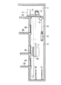
図1は本発明の一実施形態に係るトラクション方式のエレベータの概略構成を示す図である。図中の10はビルなどの建物の中に設けられた昇降路、11は屋上など昇降路10の最上部に設置された機械室を示している。機械室11には、巻き上げ機12、調速機(ガバナ)13、階床選択機14などが設けられている。
【0015】
巻き上げ機12のモータ軸にはトラクションシーブ(綱車)15が取り付けられており、巻き上げ機12の駆動により、このトラクションシーブ15が回転し、そこに巻き掛けられたロープ16を介して乗りかご17とカウンタウェイト(釣合重り)18とがつるべ式に昇降路10内を互いに反対方向に昇降するようになっている。なお、19はそらせ車であり、トラクションシーブ15と対にして用いられる。図1の例ではロープ16がトラクションシーブ15とそらせ車19に二重巻き(ダブルラップ)された構成になっているが、ロープ16の掛け方については特に限定されるものではない。
【0016】
また、20および21は昇降路10のピット部に設置された緩衝器(バッファ)であり、20は乗りかご用の緩衝器、21はカウンタウェイト用の緩衝器を示している。
【0017】
乗りかご17は、図せぬホール呼びボタンやかご呼びボタンの操作による呼び情報に応答して建物の最下階22と最上階23との間を規定の速度で移動する。また、各階床には昇降路10に対向させてホールドア24がそれぞれ設けられており、これらのホールドア24は乗りかご17の着床に伴いかご側のドア25と共に開閉する。
【0018】
このような構成において、トラクションシーブ15に巻き掛けられるロープ16には重量物であるエレベータの乗りかご17が取り付けられており、乗りかご17が昇降する度にロープ16がトラクションシーブ溝に当たるため、過酷な使用に耐えなければならない。また、ロープ16の一端には乗りかご17、他端にはカウンタウェイト18が結ばれていて、その間のロープ16が掛けられたトラクションシーブ15では、乗りかご17内の乗客の重量とカウンタウェイト18の重量との差による滑りにも耐えられるだけの高い摩擦力をロープ16との間に発生させなければならない。
【0019】
通常、トラクションシーブ15は鉄で形成され、また、ロープ16との間で十分な摩擦力を発生することができるような径を有している。ところが、機械室11の省スペース化などの要求により、トラクションシーブ15の径を小さくした場合にロープ16との接触面積が狭くなり、十分な摩擦力を発生できなくなる。このような問題を解消するため、トラクションシーブ15に対して以下のような工夫を施すものである。
【0020】
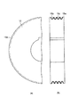
図2はトラクションシーブ15の構成を示す図であり、図2(a)はトラクションシーブ15の正面図、同図(b)はトラクションシーブ15の側部断面図である。トラクションシーブ15の外周部15aには、複数本(ここでは4本)の溝15bが形成されており、この溝15bにロープ16が巻き掛けられるようになっている。
【0021】
ここで、トラクションシーブ15の外周部15aの少なくともロープ16との接触部である溝15bの表面部分に、特定の高摩擦材15cを被覆(コーティング)しておく。上記高摩擦材15cとは、具体的にはウレタン樹脂である。このようなウレタン樹脂をシーブ外周部15aの溝15bの表面部分にコーティングしておくことで、通常鉄製で形成されるトラクションシーブ15を小径化した場合でも、ロープ16との間に十分な摩擦力を得ることができ、トラクション比を仕様値まで高めることができる。
【0022】
また、上記ウレタン樹脂としては、エレベータの使用環境に応じて、適度な表面硬度を持つ熱硬化性ウレタン樹脂または熱可塑性ウレタン樹脂を使用する。具体的には、JISで規定された硬さ試験のスケールAによる硬度が90〜99あるいはスケールDによる硬度が35〜70である硬度熱硬化性ウレタン樹脂または熱可塑性ウレタン樹脂のいずれかを使用する。このように、適度な表面硬度硬度を持つ熱硬化性ウレタン樹脂または熱可塑性ウレタン樹脂を用いることで、摩擦力だけでなく、耐久性も確保することができ、ロープ16との接触によるトラクションシーブ15の摩耗を抑えてメンテナンスの頻度を少なくすることができる。
【0023】
また、上記ウレタン樹脂は、元々、耐摩耗性の高い樹脂であり、上述したように適度な表面硬度を持つ熱硬化性ウレタン樹脂または熱可塑性ウレタン樹脂を使用すれば十分な製品寿命を期待できるが、さらに、その中にシリカ粉末粒子、黒鉛または炭素粉末粒子、窒化ホウ素粉末粒子、チタン酸カリウム繊維またはチタン酸カリウムウィスカーのいずれかの材料を充填することで、耐摩耗性をさらに高めることができる。
【0024】
シリカ粉末粒子、黒鉛または炭素粉末粒子、窒化ホウ素粉末粒子は、ウレタン樹脂に比べて硬く耐摩耗性を向上させる優れた充填材である。このような充填材を用いる場合において、極少量の充填では特性が発現されず、例えばウレタン樹脂100重量部に対して、5重量部以下の充填では無充填と同等の耐摩耗性であり、一方、30重量部以上充填すると粘度が高くなり製造性が悪くなる。チタン酸カリウム繊維、チタン酸カリウムウィスカーについては、硬い材料ではないがウレタン樹脂と馴染んで耐摩耗性を向上させる特性を有する。これについても、極少量の充填では特性が発現されず、例えばウレタン樹脂100重量部に対して、5重量部以下の充填では無充填と同等の耐摩耗性であり、一方、30重量部以上充填すると粘度が高くなり製造性が悪くなる。
【0025】
このようなことから、シリカ粉末粒子、黒鉛または炭素粉末粒子、窒化ホウ素粉末粒子、チタン酸カリウム繊維またはチタン酸カリウムウィスカーを充填する場合には、ウレタン樹脂100重量部に対して5〜30重量部の割合で充填することが好ましい。
【0026】
また、シリカ粉末粒子、黒鉛または炭素粉末粒子、窒化ホウ素粉末粒子といった粉末材に関しては、その粒径が5ミクロンメータ以下の細かい粒子では、形成前の樹脂粘度が高くなり成形が困難となり、一方、30ミクロンメータ以上の粉末粒子を混入させるとウレタン樹脂の機械強度低下を起こす。したがって、5〜30ミクロンメータの粒径粒子を使用することが好ましい。
【0027】
なお、シリカ粉末粒子、黒鉛または炭素粉末粒子、窒化ホウ素粉末粒子、チタン酸カリウム繊維またはチタン酸カリウムウィスカーのうち、少なくとも2種類以上を5〜30重量部混合し、粉末材に関してはその粒径が5〜30ミクロンメータとすることでも良く、このようにした場合でも上記同様に耐摩耗性を高めることができる。
【0028】
また、ウレタン樹脂にどの種類の粉末をどの程度充填するかについては、エレベータ機械室内環境等を考慮して決めるものとする。
【0029】
ここで、図3を参照してトラクションシーブ15の外周部15aに上述したウレタン樹脂をコーティングした場合におけるトラクション比と耐摩耗性の試験結果について述べる。トラクション比とは、トラクションシーブに掛けられたロープが滑らないでいられる両端の重量比のことであり、この値が高いほど、トラクションシーブとしての性能(摩擦力)が高いことを意味する。
【0030】
(試験1)
図3はトラクション比を測定するための装置であり、図中の31はロープ16の一端に付けられる重り(A)、32はロープ16の他端に付けられる重り(B)、33は軸、34はロープである。
【0031】
今、JISのAスケールによる硬さ試験(JISのKによる7312の7硬さ試験)で硬度96の熱硬化性ウレタン樹脂を1mmの厚さで外周部15aに被覆したトラクションシーブ15を被試験体として用い、図3に示すようなトラクション比測定装置の軸33に回転しないように取り付ける。そして、このトラクションシーブ15の外周部15aにロープ34を巻き掛け、ロープ34の一方端に重り(A)31を吊し、他方端に重り(A)31の1.5倍の重量を有する重り(B)32を吊るして、ロープ34の滑り状態を検査したところ、ロープ34が滑らなかったことが確認された。これに対し、ウレタン樹脂を被覆していない通常のトラクションシーブについても上記同様の試験を行ったところ、ロープ34が重り(A)31よりも重量のある重い重り(B)32側へ滑ることが確認された。
【0032】
また、ロープ34の両端にそれぞれ重り(A)31と重り(B)32を吊るした状態で、重り(B)32が落ちない方向(図3では反時計回り)に軸33を回転させ、トラクションシーブ15の外周部15aに施されたウレタン樹脂の耐摩耗性を試験した。トラクションシーブ15が1000回転した後にその摩耗量を測定したところ、測定誤差内の若干の摩耗量が検出されただけであり、耐摩耗性が高いことが確認された。
【0033】
また、スケールAによる硬度96の前後の熱硬化性ウレタン樹脂を用いて上記同様の試験を試みた結果、90〜99の範囲で同様結果が得られることが判明した。また、熱硬化性ウレタン樹脂に代えて、同様の硬度90〜99を有する熱可塑性ウレタン樹脂を用いた場合でも同じ結果が得られた。
【0034】
なお、スケールAによる硬さ試験では90〜99の硬度が最適なものであるが、スケールDによる硬さ試験では35〜70の硬度が最適なものとなる。スケールAとスケールDとでは硬さの試験方法が異なり、その硬度の表示レベルも違うが、その試験対象となるウレタン樹脂としての硬質は同じである。
【0035】
このように、JISで規定されたスケールAによる硬さ試験で硬度が90〜99あるいはスケールDによる硬さ試験で硬度が35〜70である熱硬化性ウレタン樹脂または熱可塑性ウレタン樹脂をトラクションシーブ15の外周部15aにコーティングしておくことで摩擦係数を上げることができ、所定のトラクション比を確保して、ロープずれを抑えて安定したエレベータの運転を行うことができると共に、トラクションシーブ15の耐摩耗性を確保してメンテナンス頻度を削減することができる。
【0036】
(試験2)
トラクションシーブ15の外周部15aにコーティングするウレタン樹脂100の中に、ウレタン樹脂100重量部に対して、平均粒子径15ミクロンメータのシリカ粉末の粒子を「2重量部、5重量部、10重量部、20重量部、30重量部、35重量部」といった割合でそれぞれ充填して上記試験1と同様の試験を行った。なお、「ウレタン樹脂100重量部に対してシリカ粉末をx重量部の割合」とは、重量比として例えばウレタン樹脂100gに対して、シリカ粉末をxgの割合で入れることを意味する。
【0037】
その結果、トラクション性能及び耐摩耗性は、シリカ粉末を2重量部の割合で充填したものはウレタン樹脂のみのシーブの場合と変わりなかった。これに対し、シリカ粉末を5重量部、10重量部、20重量部、30重量部といった割合でそれぞれに充填したシーブでは耐摩耗性の向上が見られ、トラクション性能(つまりトラクション比)は上記試験1と同様の結果が得られた。また、シリカ粉末を35重量部充填したものについては、シリカ粉末を被覆する時にボイドが多数残ってしまい、製造性が低下するといった問題があった。
【0038】
以上のような点から、ウレタン樹脂100重量部に対して、シリカ粉末を5〜30重量部の割合で充填することが好もしいものとされる。また、シリカ粉末の粒径のサイズについては、粒径が5ミクロンメータ以下の細かい粒子では、形成前の樹脂粘度が高くなり成形が困難となり、一方、30ミクロンメータ以上の粉末粒子を混入させるとウレタン樹脂の機械強度低下を起こすため、15ミクロンメータの前後、具体的には5〜30ミクロンメータの粒径粒子を使用することが好ましい。
【0039】
(試験3)
トラクションシーブ15の外周部15aにコーティングするウレタン樹脂100の中に、ウレタン樹脂100重量部に対して、平均粒子径15ミクロンメータの黒鉛粉末の粒子を「2重量部、5重量部、10重量部、20重量部、30重量部、35重量部」といった割合でそれぞれ充填して上記試験1と同様の試験を行った。
【0040】
その結果、トラクション性能及び耐摩耗性は、黒鉛粉末を2重量部の割合で充填したものはウレタン樹脂のみのシーブの場合と変わりなかった。これに対して、黒鉛粉末を5重量部、10重量部、20重量部、30重量部といった割合でそれぞれに充填したシーブでは、3000回転試験を行ってもシーブ外周部にほとんど摩耗が見られず、耐摩耗性として十分な結果が得られた。トラクション性能については上記試験1と同様の結果が得られた。また、黒鉛粉末を35重量部充填したものについては、粘度が高くなり、黒鉛粉末を被覆する時にボイドが多数残ってしまい、製造性が低下するといった問題があった。
【0041】
なお、黒鉛粉末を同様の性質を有する炭素粉末に代えて試験した場合でも上記同様の結果が得られる。
【0042】
以上のような点から、ウレタン樹脂100重量部に対して、黒鉛粉末粒子または炭素粉末を5〜30重量部充填することが好もしいものとされる。また、その粒径のサイズについては、上記シリカ粉末と同様に15ミクロンメータ前後、具体的には5〜30ミクロンメータが好ましい。
【0043】
(試験4)
トラクションシーブ15の外周部15aにコーティングするウレタン樹脂100の中に、ウレタン樹脂100重量部に対して、平均粒子径15ミクロンメータの窒化ホウ素粉末の粒子を「2重量部、5重量部、10重量部、20重量部、30重量部、35重量部」といった割合でそれぞれ充填して上記試験1と同様の試験を行った。
【0044】
その結果、トラクション性能及び耐摩耗性は、窒化ホウ素粉を2重量部の割合で充填したものはウレタン樹脂のみのシーブの場合と変わりなかった。これに対して、窒化ホウ素粉を5重量部、10重量部、20重量部、30重量部といった割合でそれぞれに充填したシーブでは、2000回転試験を行ってもシーブ外周部にほとんど摩耗が見られず、耐摩耗性として十分な結果が得られた。トラクション性能については上記試験1と同様の結果が得られた。また、窒化ホウ素粉を35重量部充填したものについては、同様の試験を試みた結果、混合時に増粘し、餅状になり被覆できなかった。
【0045】
以上のような点から、ウレタン樹脂100重量部に対して、窒化ホウ素粉を5〜30重量部充填することが好ましいものとされる。また、その粒径のサイズについては、上記シリカ粉末と同様に15ミクロンメータ前後、具体的には5〜30ミクロンメータが好ましい。
【0046】
(試験5)
トラクションシーブ15の外周部15aにコーティングするウレタン樹脂100の中に、ウレタン樹脂100重量部に対して、チタン酸カリウム繊維を「2重量部、5重量部、10重量部、20重量部、30重量部、35重量部」といった割合でそれぞれ充填して上記試験1と同様の試験を行った。
【0047】
その結果、トラクション性能及び耐摩耗性は、チタン酸カリウム繊維を2重量部の割合で充填したものはウレタン樹脂のみのシーブの場合と変わりなかった。これに対して、チタン酸カリウム繊維を5重量部、10重量部、20重量部、30重量部といった割合でそれぞれに充填したシーブでは、2000回転試験を行ってもシーブ外周部にほとんど摩耗が見られず、耐摩耗性として十分な結果が得られた。トラクション性能については上記試験1と同様の結果が得られた。また、チタン酸カリウム繊維を35重量部充填したものについては、やや粘度が高くなり、被覆する時にボイドが多数残り、製造性が低下するといった問題があった。
【0048】
なお、チタン酸カリウム繊維を同様の性質を有するチタン酸カリウムウィスカーに代えて試験した場合でも上記同様の結果が得られる。
【0049】
以上のような点から、ウレタン樹脂100重量部に対して、チタン酸カリウム繊維またはチタン酸カリウムウィスカーを5〜30重量部充填することが好もしいものとされる。
【0050】
(試験6)
トラクションシーブ15の外周部15aにコーティングするウレタン樹脂100の中に、ウレタン樹脂100重量部に対して、平均粒子径15ミクロンメータのシリカ粉末を5重量部、黒鉛粉末(または炭素粉末)を5重量部、窒化ホウ素粉末を5重量部の割合で混合して充填することにより上記試験1と同様の試験を行った。その結果、トラクション性能及び耐摩耗性は、ウレタン樹脂のみのシーブよりも優れていた。
【0051】
なお、上記混合材にチタン酸カリウム繊維(またはチタン酸カリウムウィスカー)を5重量部の割合で加えても良い。また、これらの混合材の割合は上述したように5〜30重量部が好ましく、粒子サイズについては5〜30ミクロンメータが好ましい。
【0052】
また、シリカ粉末粒子、黒鉛または炭素粉末粒子、窒化ホウ素粉末粒子、チタン酸カリウム繊維またはチタン酸カリウムウィスカーの他にも、耐摩耗性を高めることのできる材料があれば、その材料をウレタン樹脂に充填することで上記同様の効果が得られるものである。
【0053】
【発明の効果】
以上詳記したように本発明によれば、トラクションシーブの外周部の少なくともロープとの接触部に高摩擦材としてウレタン樹脂を被覆(コーティング)するようにしたため、ロープとの間の摩擦係数を高くすることができ、トラクションシーブの小径化によりロープとの接触面積が少なくなった場合でも十分な摩擦力を得ることができる。これにより、規定のトラクション比を満足して、乗りかごの安定した昇降動作を実現することができる。
【0054】
また、上記ウレタン樹脂としては、適度な表面硬度を持つ熱硬化性ウレタン樹脂または熱可塑性ウレタン樹脂を用いることで耐摩耗性が向上し、十分な製品寿命を期待することができる。
【0055】
また、上記ウレタン樹脂の中に適度な粒径のシリカ粉末粒子、黒鉛または炭素粉末粒子、窒化ホウ素粉末粒子、チタン酸カリウム繊維またはチタン酸カリウムウィスカーのいずれかを適量充填することにより、さらに耐摩耗性を向上させることができ、トラクションシーブの製品寿命の延長化を図ることができると共に、メンテナンス頻度を少なくすることができる。
【図面の簡単な説明】
【図1】本発明の一実施形態に係るトラクション方式のエレベータの概略構成を示す図。
【図2】上記エレベータに用いられるトラクションシーブの構成を示す図であり、図2(a)はトラクションシーブの正面図、同図(b)はトラクションシーブの側部断面図。
【図3】本発明によるトラクションシーブのトラクション比及び耐摩耗性について説明するための図。
【符号の説明】
10…昇降路
11…機械室
12…巻き上げ機
13…調速機
14…階床選択機
15…トラクションシーブ
15a…外周部
15b…溝
15c…高摩擦材
16…ロープ
17…乗りかご
18…カウンタウェイト
19…そらせ車
20,21…緩衝器
22…最下階
23…最上階
24…ホールドア
25…かごドア[0001]
TECHNICAL FIELD OF THE INVENTION
The present invention relates to a traction sheave used for a traction-type elevator that raises and lowers a car in a hanging manner via a rope.
[0002]
[Prior art]
An elevator is a machine that transports a passenger to an arbitrary floor by raising and lowering a car in a hoistway of a building. The command to move to each floor is issued by pressing the destination button in the car, and the hoist installed in the machine room on the roof floor is driven according to the command. As the traction sheave attached to the rotating shaft rotates with the driving of the hoist, the car moves up and down via the rope wound around the traction sheave. In this case, a balancing weight called a counterweight is provided at one end of the rope, and the balancing weight and the riding basket are vertically interposed in a slippery manner with the traction sheave interposed therebetween through the rope. You will be going up and down.
[0003]
In general, the tension of the rope differs between the car side of the rope installed on the traction sheave and the counterweight side. Even if the tension is different, it is possible to stop at each floor due to the frictional force generated on the traction sheave and the rope.
[0004]
By the way, in a traction type elevator, it is necessary to install a hoist at the top of the building in order to raise and lower the car in a hanging manner, usually a machine room is installed on the roof of the building, and there is A hoist is installed. In this case, if the hoist is reduced in size, the occupied area of the machine room can be reduced accordingly, so that space and construction costs can be reduced. In order to shorten the construction period on site, the motor and frame of the hoist are assembled at the time of shipment from the factory, and then locally lifted and installed in the elevator machine room on the rooftop with a crane. Therefore, the smaller the hoist, the smaller the crane capacity and the easier the installation.
[0005]
[Problems to be solved by the invention]
As described above, when the elevator hoist is downsized, the space in the machine room can be reduced, the construction cost can be reduced, and the construction base material such as a crane can be downsized. However, in order to reduce the size of the hoist, it is important to reduce the size of the motor and the diameter of the traction sheave around which the rope is wound. Regarding the motor, a motor that has several times the number of rotations of a conventional motor and has a moment capable of driving a rope has been developed. On the other hand, the traction sheave is usually made of iron. If the traction sheave is reduced in diameter, the contact area with the rope will be reduced, so the friction force will be insufficient, and the traction ratio (when a unit load is placed on one end of the rope, the rope will not slip on the traction sheave In addition, the ratio of the maximum load that can be placed on the other side) is reduced. For this reason, the contact between the sheave and the rope becomes unstable, and there is a possibility that a phenomenon such as the car being shifted down while getting on and off the elevator may occur.
[0006]
SUMMARY OF THE INVENTION The present invention has been made in view of the above circumstances, and has as its object to provide an elevator traction sheave capable of obtaining a specified traction ratio while suppressing a decrease in frictional force due to a reduction in diameter.
[0007]
[Means for Solving the Problems]
In order to reduce the diameter of the traction sheave, it is necessary to satisfy the specification of the traction ratio, and for that purpose, it is necessary to further increase the coefficient of friction between the rope and the rope. Therefore, the present invention is characterized in that at least a portion of the outer peripheral portion of the traction sheave that contacts the rope is coated with urethane resin as a high friction material.
[0008]
As described above, the friction coefficient can be increased by coating the urethane resin on the contact portion of the outer peripheral portion of the traction sheave with the rope, and it is sufficient even when the contact area with the rope is reduced due to the smaller diameter of the traction sheave. High frictional force can be obtained. As a result, a stable traction operation of the car can be realized while satisfying the prescribed traction ratio.
[0009]
As the urethane resin, specifically, a thermosetting urethane resin having a hardness of 90 to 99 in a hardness test on a scale A specified in JIS or a hardness of 35 to 70 in a hardness test on a scale D or a thermoplastic resin Urethane resin is used. As described above, by using a thermosetting urethane resin or a thermoplastic urethane resin having an appropriate surface hardness, abrasion resistance is improved, and a sufficient product life can be expected.
[0010]
Further, by filling silica powder particles of a suitable particle size, graphite or carbon powder particles, boron nitride powder particles, potassium titanate fiber or potassium titanate whisker in such urethane resin in an appropriate amount, furthermore, Abrasion resistance can be improved.
[0011]
Silica powder particles, graphite or carbon powder particles, and boron nitride powder particles are excellent fillers that are harder than urethane resins and improve abrasion resistance. Filling has the same abrasion resistance as non-filling, and filling more than 30 parts by weight increases viscosity and deteriorates productivity. Although potassium titanate fiber or potassium titanate whisker is not a hard material, it is compatible with urethane resin and improves wear resistance. Also in this case, the characteristics are not exhibited by filling a very small amount, filling less than 5 parts by weight has the same abrasion resistance as no filling, and filling more than 30 parts by weight increases the viscosity and deteriorates the productivity. Therefore, the filling amount of silica powder particles, graphite or carbon powder particles, boron nitride powder particles, potassium titanate fibers or potassium titanate whiskers is preferably 5 to 30 parts by weight based on 100 parts by weight of the urethane resin.
[0012]
Regarding the powder particle size of silica powder, graphite or carbon powder, and boron nitride powder, fine particles having a particle size of 5 μm or less have a high resin viscosity before formation, which makes molding difficult. Further, when powder particles having a particle size of 30 μm or more are mixed, the mechanical strength of the urethane resin is reduced. Therefore, it is preferable to use particles having a particle size of 30 μm or less.
[0013]
BEST MODE FOR CARRYING OUT THE INVENTION
Hereinafter, an embodiment of the present invention will be described with reference to the drawings.
[0014]
FIG. 1 is a diagram showing a schematic configuration of a traction type elevator according to one embodiment of the present invention. In the drawing,
[0015]
A traction sheave (a sheave) 15 is attached to a motor shaft of the
[0016]
[0017]
The
[0018]
In such a configuration, a
[0019]
Normally, the
[0020]
2A and 2B are diagrams showing a configuration of the
[0021]
Here, a specific
[0022]
In addition, as the urethane resin, a thermosetting urethane resin or a thermoplastic urethane resin having an appropriate surface hardness is used depending on the use environment of the elevator. Specifically, any one of a thermosetting urethane resin and a thermoplastic urethane resin having a hardness of 90 to 99 or a hardness of 35 to 70 according to Scale D in a hardness test specified in JIS is used. . As described above, by using a thermosetting urethane resin or a thermoplastic urethane resin having an appropriate surface hardness, not only the frictional force but also the durability can be secured, and the
[0023]
Further, the urethane resin is originally a resin having high wear resistance, and a sufficient product life can be expected by using a thermosetting urethane resin or a thermoplastic urethane resin having an appropriate surface hardness as described above. Further, by filling therein any of silica powder particles, graphite or carbon powder particles, boron nitride powder particles, potassium titanate fiber or potassium titanate whisker, the wear resistance can be further enhanced. .
[0024]
Silica powder particles, graphite or carbon powder particles, and boron nitride powder particles are excellent fillers that are harder than urethane resins and improve abrasion resistance. In the case where such a filler is used, the characteristics are not exhibited when a very small amount of the filler is used. If more than 30 parts by weight are added, the viscosity becomes high and the productivity is deteriorated. The potassium titanate fiber and the potassium titanate whisker are not hard materials, but have a characteristic of being compatible with the urethane resin and improving abrasion resistance. Also in this case, the characteristics are not exhibited when the filling amount is very small. For example, when the filling amount is 5 parts by weight or less with respect to 100 parts by weight of the urethane resin, the abrasion resistance is equivalent to the non-filling state, while the filling amount is 30 parts by weight or more. As a result, the viscosity increases and the manufacturability deteriorates.
[0025]
For this reason, when silica powder particles, graphite or carbon powder particles, boron nitride powder particles, potassium titanate fibers or potassium titanate whiskers are filled, 5 to 30 parts by weight with respect to 100 parts by weight of the urethane resin. Is preferable.
[0026]
Further, with respect to powder materials such as silica powder particles, graphite or carbon powder particles, and boron nitride powder particles, in the case of fine particles having a particle size of 5 μm or less, the resin viscosity before formation increases and molding becomes difficult. Mixing powder particles of 30 micrometers or more causes a decrease in the mechanical strength of the urethane resin. Therefore, it is preferable to use particles having a particle size of 5 to 30 micrometers.
[0027]
Among silica powder particles, graphite or carbon powder particles, boron nitride powder particles, potassium titanate fiber or potassium titanate whiskers, at least two or more kinds are mixed in an amount of 5 to 30 parts by weight. The thickness may be set to 5 to 30 micrometers, and even in this case, the wear resistance can be improved as described above.
[0028]
In addition, what kind of powder is filled into the urethane resin and how much is to be determined in consideration of the elevator machine room environment and the like.
[0029]
Here, the traction ratio and the wear resistance test results when the outer
[0030]
(Test 1)
FIG. 3 shows an apparatus for measuring the traction ratio, in which 31 is a weight (A) attached to one end of the
[0031]
Now, the
[0032]
Further, with the weights (A) 31 and the weights (B) 32 suspended from both ends of the
[0033]
In addition, as a result of trying the same test as above using a thermosetting urethane resin having a hardness of around 96 according to the scale A, it was found that the same result was obtained in the range of 90 to 99. The same results were obtained when a thermoplastic urethane resin having a similar hardness of 90 to 99 was used instead of the thermosetting urethane resin.
[0034]
In the hardness test using the scale A, a hardness of 90 to 99 is optimal, but in the hardness test using the scale D, a hardness of 35 to 70 is optimal. The scale A and the scale D have different hardness test methods and different display levels of the hardness, but the hardness of the urethane resin to be tested is the same.
[0035]
Thus, a thermosetting urethane resin or a thermoplastic urethane resin having a hardness of 90 to 99 in a hardness test according to JIS or a hardness of 35 to 70 in a hardness test according to Scale D is subjected to
[0036]
(Test 2)
In the urethane resin 100 which coats the outer
[0037]
As a result, traction performance and abrasion resistance were the same as those of the case where the silica powder was filled at a ratio of 2 parts by weight and the case where only the urethane resin was used. On the other hand, the sheaves filled with silica powder in the proportions of 5 parts by weight, 10 parts by weight, 20 parts by weight, and 30 parts by weight respectively show improved wear resistance, and the traction performance (that is, the traction ratio) is determined by the above test. The same result as in Example 1 was obtained. Further, when the silica powder is filled with 35 parts by weight, there is a problem that many voids remain when the silica powder is coated, and the productivity is reduced.
[0038]
In view of the above, it is preferable to fill the silica powder at a ratio of 5 to 30 parts by weight with respect to 100 parts by weight of the urethane resin. Regarding the particle size of the silica powder, fine particles having a particle size of 5 μm or less have a high resin viscosity before forming and are difficult to mold. On the other hand, if powder particles of 30 μm or more are mixed, In order to reduce the mechanical strength of the urethane resin, it is preferable to use particles having a particle size of about 15 μm, specifically 5 to 30 μm.
[0039]
(Test 3)
In the urethane resin 100 which coats the outer
[0040]
As a result, traction performance and abrasion resistance were the same as those in the case where the graphite powder was filled at a ratio of 2 parts by weight, as compared with the case where the urethane resin alone was used. On the other hand, in a sieve filled with graphite powder at a ratio of 5 parts by weight, 10 parts by weight, 20 parts by weight, and 30 parts by weight, almost no wear was observed on the outer periphery of the sheave even after the 3000 rotation test. Sufficient results were obtained as abrasion resistance. Regarding traction performance, the same results as in Test 1 were obtained. In addition, the powder filled with 35 parts by weight of graphite powder has a problem that the viscosity becomes high, and a large number of voids remain when the graphite powder is coated, thereby reducing the productivity.
[0041]
It should be noted that the same result as described above can be obtained even when the test is performed by replacing the graphite powder with a carbon powder having similar properties.
[0042]
In view of the above, it is preferable to fill 5 to 30 parts by weight of graphite powder particles or carbon powder with respect to 100 parts by weight of the urethane resin. Further, the size of the particle size is preferably about 15 μm, similarly to the above silica powder, specifically 5 to 30 μm.
[0043]
(Test 4)
In the urethane resin 100 which coats the outer
[0044]
As a result, the traction performance and the wear resistance were the same as those of the case where the boron nitride powder was filled at a ratio of 2 parts by weight and the case where the urethane resin alone was used. On the other hand, in the case of a sieve filled with boron nitride powder at a ratio of 5 parts by weight, 10 parts by weight, 20 parts by weight, and 30 parts by weight, the outer periphery of the sheave is almost worn even after a 2,000 rotation test. And sufficient results were obtained as abrasion resistance. Regarding traction performance, the same results as in Test 1 were obtained. The same test was carried out for the powder filled with 35 parts by weight of boron nitride powder. As a result, the viscosity increased during mixing, and the mixture became cake-like and could not be covered.
[0045]
In view of the above, it is preferable to fill the boron nitride powder with 5 to 30 parts by weight based on 100 parts by weight of the urethane resin. Further, the size of the particle size is preferably about 15 μm, similarly to the above silica powder, specifically 5 to 30 μm.
[0046]
(Test 5)
In the urethane resin 100 coated on the outer
[0047]
As a result, the traction performance and the abrasion resistance were the same as those obtained by filling the potassium titanate fiber at a ratio of 2 parts by weight with the case of the sieve containing only the urethane resin. On the other hand, in a sieve filled with potassium titanate fiber at a ratio of 5 parts by weight, 10 parts by weight, 20 parts by weight, or 30 parts by weight, almost no wear was found on the outer periphery of the sheave even after a 2,000 rotation test. However, sufficient results were obtained as wear resistance. Regarding traction performance, the same results as in Test 1 were obtained. In addition, when filled with 35 parts by weight of potassium titanate fiber, there was a problem that the viscosity was slightly increased, a large number of voids remained at the time of coating, and the productivity was reduced.
[0048]
In addition, the same result as described above can be obtained when the test is performed by replacing the potassium titanate fiber with a potassium titanate whisker having similar properties.
[0049]
From the above points, it is preferable to fill 5 to 30 parts by weight of potassium titanate fiber or potassium titanate whisker with respect to 100 parts by weight of the urethane resin.
[0050]
(Test 6)
In the urethane resin 100 coated on the outer
[0051]
Note that potassium titanate fiber (or potassium titanate whisker) may be added to the above-mentioned mixed material at a ratio of 5 parts by weight. As described above, the ratio of these mixed materials is preferably 5 to 30 parts by weight, and the particle size is preferably 5 to 30 μm.
[0052]
In addition, besides silica powder particles, graphite or carbon powder particles, boron nitride powder particles, potassium titanate fiber or potassium titanate whisker, if there is a material that can enhance wear resistance, the material is converted to urethane resin. The same effect as described above can be obtained by filling.
[0053]
【The invention's effect】
As described above in detail, according to the present invention, at least the outer peripheral portion of the traction sheave is contacted with the rope by urethane resin as a high friction material, so that the friction coefficient between the rope and the rope is increased. And a sufficient frictional force can be obtained even when the contact area with the rope is reduced due to the reduction in the diameter of the traction sheave. As a result, a stable traction operation of the car can be realized while satisfying the prescribed traction ratio.
[0054]
Further, by using a thermosetting urethane resin or a thermoplastic urethane resin having an appropriate surface hardness as the urethane resin, abrasion resistance is improved and a sufficient product life can be expected.
[0055]
Further, by filling the urethane resin with an appropriate amount of silica powder particles, graphite or carbon powder particles, boron nitride powder particles, potassium titanate fiber or potassium titanate whisker having an appropriate particle size, the abrasion resistance is further increased. Performance can be improved, the product life of the traction sheave can be extended, and the frequency of maintenance can be reduced.
[Brief description of the drawings]
FIG. 1 is a diagram showing a schematic configuration of a traction-type elevator according to an embodiment of the present invention.
FIG. 2 is a diagram showing a configuration of a traction sheave used for the elevator, FIG. 2 (a) is a front view of the traction sheave, and FIG. 2 (b) is a side sectional view of the traction sheave.
FIG. 3 is a diagram for explaining the traction ratio and wear resistance of the traction sheave according to the present invention.
[Explanation of symbols]
DESCRIPTION OF
Claims (10)
上記ロープが巻き掛けられる外周部の少なくとも上記ロープとの接触部に、高摩擦材としてウレタン樹脂が被覆されていることを特徴とするエレベータ用トラクションシーブ。In a traction sheave for elevators installed on a rope hoist that raises and lowers a rider and a counterweight in a hanging manner,
A traction sheave for an elevator, wherein a urethane resin is coated as a high friction material on at least a contact portion of an outer peripheral portion around which the rope is wound with the rope.
上記ロープが巻き掛けられる外周部の少なくとも上記ロープとの接触部に、JISで規定されたスケールAによる硬さ試験で硬度が90〜99あるいはスケールDによる硬さ試験で硬度が35〜70である熱硬化性ウレタン樹脂または熱可塑性ウレタン樹脂が被覆されていることを特徴とするエレベータ用トラクションシーブ。In a traction sheave for elevators installed on a rope hoist that raises and lowers a rider and a counterweight in a hanging manner,
A hardness of 90 to 99 in a hardness test on a scale A specified in JIS or a hardness of 35 to 70 in a hardness test on a scale D at least at a contact portion of the outer peripheral portion around which the rope is wound with the rope. An elevator traction sheave coated with a thermosetting urethane resin or a thermoplastic urethane resin.
上記ロープが巻き掛けられる外周部の少なくとも上記ロープとの接触部に、高摩擦材としてウレタン樹脂が被覆されており、そのウレタン樹脂に耐摩耗性を高める特定の材料が充填されていることを特徴とするエレベータ用トラクションシーブ。In a traction sheave for elevators installed on a rope hoist that raises and lowers a rider and a counterweight in a hanging manner,
A urethane resin is coated as a high friction material on at least a contact portion of the outer periphery around which the rope is wound with the rope, and the urethane resin is filled with a specific material that enhances abrasion resistance. Traction sheave for elevators.
Priority Applications (1)
| Application Number | Priority Date | Filing Date | Title |
|---|---|---|---|
| JP2002270072A JP2004106984A (en) | 2002-09-17 | 2002-09-17 | Traction sheave for elevator |
Applications Claiming Priority (1)
| Application Number | Priority Date | Filing Date | Title |
|---|---|---|---|
| JP2002270072A JP2004106984A (en) | 2002-09-17 | 2002-09-17 | Traction sheave for elevator |
Publications (1)
| Publication Number | Publication Date |
|---|---|
| JP2004106984A true JP2004106984A (en) | 2004-04-08 |
Family
ID=32267817
Family Applications (1)
| Application Number | Title | Priority Date | Filing Date |
|---|---|---|---|
| JP2002270072A Pending JP2004106984A (en) | 2002-09-17 | 2002-09-17 | Traction sheave for elevator |
Country Status (1)
| Country | Link |
|---|---|
| JP (1) | JP2004106984A (en) |
Cited By (7)
| Publication number | Priority date | Publication date | Assignee | Title |
|---|---|---|---|---|
| JP2006160415A (en) * | 2004-12-03 | 2006-06-22 | Toshiba Elevator Co Ltd | Speed detector fitting device and fitting method of elevator control renewal |
| WO2010071061A1 (en) * | 2008-12-17 | 2010-06-24 | 三菱電機株式会社 | Rope for elevator |
| CN102745579A (en) * | 2011-04-21 | 2012-10-24 | 新明和工业株式会社 | Lifting driving device and mechanical parking equipment having the same |
| WO2014023449A1 (en) * | 2012-08-07 | 2014-02-13 | Schaeffler Technologies AG & Co. KG | Belt drive for a motor vehicle |
| CN108861955A (en) * | 2017-05-11 | 2018-11-23 | 蒂森克虏伯电梯(上海)有限公司 | The drawing belt and its belt wheel of elevator device and the elevator for using the drawing belt and belt wheel |
| KR102528654B1 (en) * | 2022-12-14 | 2023-05-08 | 이재길 | Wire sheave for stage equipment and its manufacturing method |
| EP3945062B1 (en) * | 2020-08-01 | 2025-06-18 | Otis Elevator Company | High friction and wear resistant elevator sheave liner |
-
2002
- 2002-09-17 JP JP2002270072A patent/JP2004106984A/en active Pending
Cited By (14)
| Publication number | Priority date | Publication date | Assignee | Title |
|---|---|---|---|---|
| JP2006160415A (en) * | 2004-12-03 | 2006-06-22 | Toshiba Elevator Co Ltd | Speed detector fitting device and fitting method of elevator control renewal |
| DE112009002722B4 (en) * | 2008-12-17 | 2016-12-15 | Mitsubishi Electric Corp. | Carrying rope for a lift |
| CN102216192A (en) * | 2008-12-17 | 2011-10-12 | 三菱电机株式会社 | Rope for elevator |
| US8402731B2 (en) | 2008-12-17 | 2013-03-26 | Mitsubishi Electric Corporation | Elevator rope |
| KR101273854B1 (en) | 2008-12-17 | 2013-06-11 | 미쓰비시덴키 가부시키가이샤 | Rope for elevator |
| CN102216192B (en) * | 2008-12-17 | 2013-08-21 | 三菱电机株式会社 | Rope for elevator |
| JP5300868B2 (en) * | 2008-12-17 | 2013-09-25 | 三菱電機株式会社 | Elevator rope |
| WO2010071061A1 (en) * | 2008-12-17 | 2010-06-24 | 三菱電機株式会社 | Rope for elevator |
| CN102745579A (en) * | 2011-04-21 | 2012-10-24 | 新明和工业株式会社 | Lifting driving device and mechanical parking equipment having the same |
| WO2014023449A1 (en) * | 2012-08-07 | 2014-02-13 | Schaeffler Technologies AG & Co. KG | Belt drive for a motor vehicle |
| US9856970B2 (en) | 2012-08-07 | 2018-01-02 | Schaeffler Technologies AG & Co. KG | Belt drive for a motor vehicle |
| CN108861955A (en) * | 2017-05-11 | 2018-11-23 | 蒂森克虏伯电梯(上海)有限公司 | The drawing belt and its belt wheel of elevator device and the elevator for using the drawing belt and belt wheel |
| EP3945062B1 (en) * | 2020-08-01 | 2025-06-18 | Otis Elevator Company | High friction and wear resistant elevator sheave liner |
| KR102528654B1 (en) * | 2022-12-14 | 2023-05-08 | 이재길 | Wire sheave for stage equipment and its manufacturing method |
Similar Documents
| Publication | Publication Date | Title |
|---|---|---|
| WO2003050348A1 (en) | Elevator rope and elevator device | |
| CN1294069C (en) | elevator | |
| US9994424B2 (en) | Elevator system | |
| JP2004525837A (en) | High-strength wire with thin elevator rope | |
| WO2001068973A1 (en) | Rope, and elevator using the same | |
| US4230205A (en) | Elevator system | |
| JP2006513962A (en) | Elevator sheave | |
| JP2004106984A (en) | Traction sheave for elevator | |
| JP4296152B2 (en) | Elevator rope and elevator equipment | |
| CN100540441C (en) | Elevator with a movable elevator car | |
| JP6511232B2 (en) | elevator | |
| JPWO2007007400A1 (en) | Elevator equipment | |
| JP2004137003A (en) | Elevator equipment | |
| CN1220616C (en) | Elevator device | |
| JP4312721B2 (en) | Elevator equipment | |
| CN1264740C (en) | Elevator device | |
| JP2005527449A (en) | Elevator manufacturing method and elevator delivery system | |
| CN1063727C (en) | Emergency braking of mine hoist | |
| JPWO2004101419A1 (en) | Elevator equipment | |
| CN109562912B (en) | Elevator device | |
| JPS594589A (en) | Drive sheave |
Legal Events
| Date | Code | Title | Description |
|---|---|---|---|
| A621 | Written request for application examination |
Free format text: JAPANESE INTERMEDIATE CODE: A621 Effective date: 20050829 |
|
| A977 | Report on retrieval |
Effective date: 20080425 Free format text: JAPANESE INTERMEDIATE CODE: A971007 |
|
| A131 | Notification of reasons for refusal |
Effective date: 20080513 Free format text: JAPANESE INTERMEDIATE CODE: A131 |
|
| A02 | Decision of refusal |
Free format text: JAPANESE INTERMEDIATE CODE: A02 Effective date: 20081007 |