JP2004106983A - Sheet feeding cassette and image formation device - Google Patents
Sheet feeding cassette and image formation device Download PDFInfo
- Publication number
- JP2004106983A JP2004106983A JP2002270052A JP2002270052A JP2004106983A JP 2004106983 A JP2004106983 A JP 2004106983A JP 2002270052 A JP2002270052 A JP 2002270052A JP 2002270052 A JP2002270052 A JP 2002270052A JP 2004106983 A JP2004106983 A JP 2004106983A
- Authority
- JP
- Japan
- Prior art keywords
- sheet
- remaining amount
- auxiliary frame
- image forming
- forming apparatus
- Prior art date
- Legal status (The legal status is an assumption and is not a legal conclusion. Google has not performed a legal analysis and makes no representation as to the accuracy of the status listed.)
- Granted
Links
- 230000015572 biosynthetic process Effects 0.000 title 1
- 238000001514 detection method Methods 0.000 claims description 5
- 230000003287 optical effect Effects 0.000 description 5
- 238000004140 cleaning Methods 0.000 description 3
- 238000003780 insertion Methods 0.000 description 3
- 230000037431 insertion Effects 0.000 description 3
- 238000000034 method Methods 0.000 description 3
- 230000001681 protective effect Effects 0.000 description 3
- 210000000078 claw Anatomy 0.000 description 2
- 230000005484 gravity Effects 0.000 description 2
- 238000011144 upstream manufacturing Methods 0.000 description 2
- 230000008602 contraction Effects 0.000 description 1
- 230000007423 decrease Effects 0.000 description 1
- 238000010438 heat treatment Methods 0.000 description 1
- 108091008695 photoreceptors Proteins 0.000 description 1
Images


Classifications
-
- B—PERFORMING OPERATIONS; TRANSPORTING
- B65—CONVEYING; PACKING; STORING; HANDLING THIN OR FILAMENTARY MATERIAL
- B65H—HANDLING THIN OR FILAMENTARY MATERIAL, e.g. SHEETS, WEBS, CABLES
- B65H1/00—Supports or magazines for piles from which articles are to be separated
- B65H1/08—Supports or magazines for piles from which articles are to be separated with means for advancing the articles to present the articles to the separating device
- B65H1/12—Supports or magazines for piles from which articles are to be separated with means for advancing the articles to present the articles to the separating device comprising spring
-
- B—PERFORMING OPERATIONS; TRANSPORTING
- B65—CONVEYING; PACKING; STORING; HANDLING THIN OR FILAMENTARY MATERIAL
- B65H—HANDLING THIN OR FILAMENTARY MATERIAL, e.g. SHEETS, WEBS, CABLES
- B65H2405/00—Parts for holding the handled material
- B65H2405/30—Other features of supports for sheets
- B65H2405/32—Supports for sheets partially insertable - extractable, e.g. upon sliding movement, drawer
-
- B—PERFORMING OPERATIONS; TRANSPORTING
- B65—CONVEYING; PACKING; STORING; HANDLING THIN OR FILAMENTARY MATERIAL
- B65H—HANDLING THIN OR FILAMENTARY MATERIAL, e.g. SHEETS, WEBS, CABLES
- B65H2511/00—Dimensions; Position; Numbers; Identification; Occurrences
- B65H2511/10—Size; Dimensions
- B65H2511/15—Height, e.g. of stack
-
- B—PERFORMING OPERATIONS; TRANSPORTING
- B65—CONVEYING; PACKING; STORING; HANDLING THIN OR FILAMENTARY MATERIAL
- B65H—HANDLING THIN OR FILAMENTARY MATERIAL, e.g. SHEETS, WEBS, CABLES
- B65H2551/00—Means for control to be used by operator; User interfaces
- B65H2551/20—Display means; Information output means
Landscapes
- Engineering & Computer Science (AREA)
- Mechanical Engineering (AREA)
- Sheets, Magazines, And Separation Thereof (AREA)
- Controlling Sheets Or Webs (AREA)
Abstract
Description
【0001】
【発明の属する技術分野】
本発明は、シートを収納する給紙カセット及びこれを有する電子写真方式等の画像形成装置に関するものである。
【0002】
【従来の技術】画像形成装置の給紙カセットとして、主枠体と、この主枠体に摺動自在に設けられた補助枠体とを有し、収納するシートサイズに応じて補助枠体を伸縮させることは公知である(特許文献1参照)。また、給紙カセットのシート残量を検出してシート残量を給紙カセットに表示するシート残量機構を有するものも公知である(特許文献2及び特許文献3参照)。
【0003】
【特許文献1】
特開平5−51136号公報
【特許文献1】
特開平6−271141号公報
【特許文献1】
特開平10−194479号公報
【0004】
【発明が解決しようとする課題】
しかしながら、従来においては、伸縮自在の給紙カセットにシート残量表示機構を適用したものは知られていない。従来のシート残量表示機構は、シートを積載するシート積載板に連結された残量表示部を動かす構成であるため、これを伸縮自在とした給紙カセットに適用しようとすると、シート積載板が設けられた主枠体にシート残量表示部を設けざるを得ない。画像形成装置に給紙カセットを装着した場合、補助枠体が正面側にあって、主枠体が奥側に配置されるとき、主枠体にシート残量表示部を設けた構成では、ユーザが見にくく、シート残量の確認が困難であるという問題を生じる。
【0005】本発明は、伸縮自在の給紙カセットにおいて、シートの残量を容易に確認することができる給紙カセット及びこれを有する画像形成装置を提供することを目的としている。
【0006】
【課題を解決するための手段】上記目的を達成するため、本発明の第1の特徴とするところは、主枠体と、この主枠体に対して摺動自在に設けられた補助枠体と、積載されたシート残量に応じて動くシート残量検出部と、このシート残量検出部に連結され、且つ前記補助枠体の摺動に応じて動く連結部と、この連結部の動きに応じて前記補助枠体にシート残量を表示するシート残量表示部とを具備する給紙カセットにある。したがって、補助枠体にシート残量表示部を設けることができるので、主枠体が奥側に配置される場合であっても、容易にシート残量を確認することができる。
【0007】主枠体にシートを積載するシート積載板を設け、このシート積載板に連結部を連結することが好ましい。シート積載板には、シートの残量に応じて回動、傾斜、上下動等の動きをなす機構が設けられるが、このシート積載板の動きをシート残量検出部により検出することができる。この場合、シート残量検出部がシート残量に応じて回転させるようにし、このシート検出部の回転を連結部を介してシート残量表示部に伝達することができる。連結部とシート残量表示部とのいずれか一方にレバーを、他方にカムを設け、連結部の回転をシート残量表示部に設けられた表示片の上下動に変換することが好ましい。
【0008】連結部は、補助枠体に設けられた支持部により回動のみ許されるように位置を固定することが好ましい。この連結部は、補助枠体を伸ばした場合には、ユーザが直接触るおそれがあるので、防護部を設けることが好ましい。防護部は、ひさし状に形成されて連結部の上部に設けられる防護壁や連結部を囲む防護カバーとして構成することができる。
【0009】本発明の第2の特徴とするところは、画像形成装置本体と、この画像形成装置本体に収納された像形成手段と、この像形成手段に搬送すべきシートを収納する給紙カセットとを有し、前記給紙カセットは、主枠体と、この主枠体に対して摺動自在に設けられた補助枠体と、積載されたシート残量に応じて動くシート残量検出部と、このシート残量検出部に連結され、且つ前記補助枠体の摺動に応じて動く連結部と、この連結部の動きに応じて前記補助枠体にシート残量を表示するシート残量表示部とを具備し、前記補助枠体が伸びたとき、前記補助枠体の少なくとも一部が前記画像形成装置本体よりも正面側に突出する画像形成装置にある。このように、給紙カセットの補助枠体を画像形成装置本体より突出自在の構成としたので、小サイズのシートを給紙カセットに収納する場合は、給紙カセットを縮めて画像形成装置全体をコンパクトにすることできるし、大サイズのシートに対しては、給紙カセットを伸ばすことにより収納することができる。また、このように給紙カセットを伸縮した場合にも、補助枠体に設けたシート残量表示部によりシート残量を確認することができる。
【0010】
【発明の実施の形態】次に本発明の実施形態を図面に基づいて説明する。
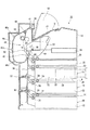
図1において、本発明の実施形態に係る画像形成装置10の概要が示されている。画像形成装置10は、画像形成装置本体12を有し、この画像形成装置本体12内に像形成手段14が搭載され、この画像形成装置本体12の上部に後述する排出部16が設けられていると共に、この画像形成装置本体12の下部に例えば2段の給紙ユニット18,18が配置されている。さらに、画像形成装置本体12の下方には、オプションとして着脱装着される2段の給紙ユニット18,18が配置されている。
【0011】それぞれの給紙ユニット18は、給紙ユニット本体20と、用紙が収納される給紙カセット22とを有する。給紙カセット22は、給紙ユニット本体20に対して摺動自在に装着され、正面方向(図1の右方向)に引き出される。また、給紙カセット22の奥端近傍上部にはナジャーロール24が配置され、このナジャーロール24の前方にリタードロール26及びフィードロール28が配置されている。さらにオプションの給紙ユニット18,18には、それぞれ対をなす送りロール30が設けられている。
【0012】上記複数の給紙カセット22の少なくとも一つは、伸縮自在のもので、主枠体32と、この主枠体32に対して摺動自在に設けられた補助枠体34とを有し、図1において2点鎖線で示すように、補助枠体34は、伸ばした場合には、画像形成装置本体12から正面方向に少なくとも補助枠体34の一部である長さAだけ突出し、縮めた場合には、画像形成装置本体12の正面壁面に一致するようにしてある。この給紙カセット22については後に詳述する。
【0013】搬送路36は、最下端の給紙ユニット18のナジャーロール24から排出口38までの用紙通路であり、この搬送路36は、画像形成装置本体12の裏面(図1の左側面)近傍にあって、最下端の給紙ユニット18の送りロール30から後述する定着装置62まで略鉛直に形成されている部分を有する。この搬送路36の定着装置64の上流側に後述する転写装置56と像担持体54が配置され、さらに転写装置62と像担持体54の上流側にレジストロール40が配置されている。さらに、搬送路36の排出口38の近傍には排出ロール42が配置されている。
【0014】したがって、前述した給紙ユニット18から搬送されたシートは、搬送路36のレジストロール40により一時停止され、所定のタイミングで像形成手段14に送られて像が形成され、排出ロール42により排出部16へ排出される。
【0015】ただし、両面印刷の場合は、反転路に戻される。即ち、排出ロール42の手前は2股に別れ、その分かれた部分に切換爪44が設けられていると共に、分かれた部分からレジストロール42まで戻る反転路46が形成されている。この反転路46には搬送ロール48a〜48cが設けられており、両面印刷の場合には、切換爪44が反転路46を開く側に切り換えられ、排出ロール42にシートの後端手前がかかる時点で排出ロール42が反転し、記録媒体が反転路46に導かれ、レジストロール38、転写装置62と像担持体54及び定着装置64を通って排出部16へ排出されるものである。
【0016】排出部16は、画像形成装置本体12に対して回動自在の傾斜部50を有する。この傾斜部50は、排出口部分が低く、正面方向(図1の右方向)に向けて徐々に高くなるよう傾斜しており、排出口部分を下端とし、高くなった先端を上端としている。この傾斜部50は下端を中心に回動自在であるよう画像形成装置本体12に支持されている。図1で2点鎖線で示すように、傾斜部50を上方に回転して開いたときには、開放部52が形成され、この開放部52を介して後述するプロセスカートリッジ66が脱着できるようにしてある。
【0017】像形成手段14は、例えば電子写真方式のもので、感光体からなる像担持体54と、この像担持体54を一様帯電する例えば帯電ロールからなる帯電装置56と、この帯電装置56により帯電された像担持体54に、光により潜像を書き込む光書込み装置58と、この光書込み装置58により形成された像担持体54の潜像を現像剤により可視化する現像装置60と、この現像装置60による現像剤像を用紙に転写する例えば転写ロールからなる転写装置62と、像担持体54に残存する現像剤をクリーニングする例えばブレードからなるクリーニング装置63と、転写装置62により転写された用紙上の現像剤像を用紙に定着させる例えば加圧ロールと加熱ロールとからなる定着装置64とから構成されている。光書込み装置58は例えば走査型のレーザ露光装置からなり、前述した給紙ユニット18と平行で画像形成装置本体12の正面近傍に配置され、現像装置60内を横切って像担持体54を露光する。また、現像装置60は、像担持体54と対向する現像ロール66を有する。
【0018】プロセスカートリッジ68は、像担持体54、帯電装置56、現像装置60及びクリーニング装置64を一体化したものである。このプロセスカートリッジ68は、排出部16の傾斜部50の直近下方に配置されており、前述したように、傾斜部50を開いたときに形成される開放部52を介して脱着される。
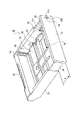
【0019】図2及び図3において、給紙カセット22の一例が示されている。主枠体32は、給紙カセット22の挿入方向奥側に前述したリタードロール26を支持している。また、この主枠体32の背面部分にシートを案内するガイド部70が形成されている。補助枠体34は、該補助枠体34の側面部分が主枠体32の側面部分に摺動自在に挿入されている。この補助枠体34は、正面部分に正面カバー部72が設けられ、この正面カバー部72が長さAだけ画像形成装置本体から突出するようになっている。また、この補助枠体34内には、シート後端ガイド74が前後方向に移動自在に立設されている。給紙がセット22に収納されるシートは、シート後端ガイド74に後端が当接される。異なるシートを収納する場合は、補助枠体34を主枠体32から伸縮させてもよいし、補助枠体34が伸ばされている状態にあっては、シート後端ガイド74を移動調節してもよい。
【0020】シート積載板76は、主枠体32の底部に揺動自在に設けられている。このシート積載板76は、シートの残量に応じて上下動し、このシート積層板76には、シート積載板76の最上位に積層されたシートの搬送位置を常に一定に保つための制御機構が設けられている。
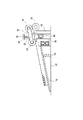
【0021】この制御機構は、前述したナジャーロール24の位置を電気的に検出し、シート積層板76をモータ等により駆動する電気的なものから構成してもよいが、この実施形態にあっては、機械的なものが用いられており、その一例が図4に示されている。
【0022】図4において、ナジャーロール24は、フィードロール28の回転軸を支点として揺動する揺動アーム78に支持されている。この揺動アーム78は、上方から第1の弾性体80により下方へ付勢されている。また、この揺動アーム78の位置を検出するアクチュエータ82が当接している。このアクチュエータ82には、ラチェット84が連結されている。このラチェット84は主枠体32に対して左右方向に移動自在であり、このラチェット84に対向してラック86が主枠体32に固定されている。ラチェット84とラック86にはピニオンギア88が噛み合っている。このピニオンギア88は、シート積層板76に回転自在に支持されている。また、シート積層板76は、主枠体32との間に第2の弾性体90が介在され、この第2の弾性体90により、シート搬出側が上方へ向かうよう付勢されている。
【0023】シート積層板76は、ラチェット84が図中右側の位置にある場合は、ラチェット84とラック86との間にはピニオンギア88が噛み合っているため、位置が固定されている。シート積層板76に積層されたシートは、第1の弾性体80により、ナジャーロール24が所定圧力で押し付けられている。ここで、シートがナジャーロール24の回転により送り出され、リタードロール26とフィードロール28とにより一枚一枚捌かれ、搬送されていくと、揺動アーム78が下方に下がる。揺動アーム78が下方に下がると、アクチュエータ82が押されて下方に移動し、ラチェット84が図中左方向に移動する。これにより、ラチェット84とピニオンギア88との噛み合いが外れ、第2の弾性体90により、ピニオンギア88がラック86に沿って回転し、シート積載板76が上昇する。これによりアクチュエータ82が第1の弾性体80とバランスするまで上昇する。これによりラチェット84が図中右側に移動してピニオンギア88と噛み合い、シート積載板76が停止し、再びナジャーロール24がシートに所定の位置で接触するようになる。
【0024】このように、シート残量に応じてシート積層板76が上下動する。この実施形態においては、シート積層板76の上下動に応じてシートの残量を表示するシート残量表示機構92が設けられている。
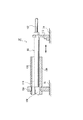
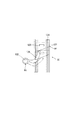
【0025】図5乃至図9において、シート残量表示機構92は、給紙カセット22の側部内面近傍に配置され、シート残量検出部94と、このシート残量検出部94に連結された連結部96とを有する。シート残量検出部94は連結部96と一体で連結部96の一端近傍に設けられている。このシート残量検出部94は、シート積載板76に形成されたけ係合溝98に係合されており、後述するように、シート積載板76の上下動に応じて、連結部96を中心として回動するようになっている。
【0026】連結部96は、シート残量検出部94が設けられた第1の回動軸100と、この第1の回動軸100に摺動自在に挿入された第2の回動軸102とを有する。図8に示すように、第1の回動軸100は、主枠体32に設けられた第1の支持部104に回動のみ許されるように支持されている。また、この第1の回動軸100には、第2の回動軸102が挿入される挿入孔106が形成されていると共に、この挿入溝106に沿って摺動溝108が形成されている。一方、第2の回動軸102の一端近傍には、突出部110が形成され、この突出部110が摺動溝108に摺動自在に挿入されている。また、第2の回動軸102は、補助枠体34に設けられた第2の支持部112に回動のみ許されるように支持されている。したがって、補助枠体34が主枠体32に対して移動すると、補助枠体34に設けられた第2の支持部112を介して、第1の回動軸100に対して第2の回動軸102が移動する。また、第1の回動軸100が回動すれば、第2の回動軸102がそれに伴って回動する。
【0027】この連結部96の上方には、図2及び図3に示すように、防護部114が設けられている。この防護部114は、この実施形態においては、補助枠体34の側部内面に突出したひさし状の防護壁として構成され、連結部96の上方を覆い、ユーザが直接連結部96に触るのを防止している。この防護部114は、他の実施形態として、連結部96の一部又は全体を覆うカバー部として構成することもできる。
【0028】シート残量表示機構92は、シート残量表示部116を有する。このシート残量表示部116は、補助枠体34の正面カバー部72に形成された窓部118と、この窓部118内で移動自在に配置された表示片120とを有する。この表示片120は、カム122と一体に形成されている。カム122は、例えば正面カバー部72に形成されたレール部124に摺動自在であり、上下方向に移動する。このカム122の下面には例えば斜めに形成されたカム面を有する。一方、連結部94の第2の回動軸102の先端には、レバー126が第2の回動軸102と一体に形成され、このレバー126の先端がカム122のカム面に当接している。したがって、第2の回動軸102が回動すると、レバー126がカム122のカム面に沿って摺動し、カム122がレール部124に沿って摺動し、表示片120が上下動してシート残量を表示するものである。
なお、カム122は、該カム122の重力によりレバー126との当接を確保してもよいが、弾性体を設けてカム122を下方へ付勢してもよい。
【0029】次に上記実施形態の作用について説明する。
像担持体54が帯電装置56により一様に帯電され、この帯電された像担持体54には、画像信号に基づいて光書込み装置58から発した光が照射され、潜像が形成される。この光書込み装置58により形成された像担持体54の潜像は現像装置60の現像剤により可視化される。
【0030】一方、サイズ信号等により給紙ユニット18の一つが選択され、給紙カセット22の一つに収納されたシートはナジャーロール24により送り出され、リタードロール26及びフィードロール28により捌かれてレジストロール40まで達し、このレジストロール40により一次停止され、タイミングをとって転写装置62と像担持体54との間に導かれる。
【0031】このようにして記録媒体が転写装置62と像担持体54との間に導かれると、像担持体54上の現像剤が転写装置62により記録媒体に転写される。この現像剤が転写されたシートは、定着装置64を通って排出部16へ排出されるものである。
【0032】給紙カセット22においては、シート積載板76に積載されたシートの残量が徐々に少なくなると、シート積載板76が徐々に上昇する。シート積載板76が上昇すると、シート積載板76に係合しているシート残留表示機構92のシート残量検出部94が回転する。このシート残量検出部94が回転すると、連結部96がレバー126と共に回転し、カム122が表示片120と共に該カム122の重力又は弾性体の付勢により下方向へ移動し、窓部118における表示片120の位置によってシート残量を表示する。
【0033】主枠体32に対して補助枠体34を伸縮させると、第1の回動軸100に対して第2の回動軸102も伸縮し、カム122とレバー126との当接が保たれ、シート残量残量表示部116には何ら支障無しにシート残量を表示することができるものである。
【0034】なお、上記実施形態におけるシート残量表示機構は一例であって、主枠体32に対する補助枠体34の伸縮に対応する機構であればよい。
【0035】
【発明の効果】以上述べたように、本発明によれば、伸縮自在の給紙カセットにおいて、主枠体に対する補助枠体の摺動に連動して伸縮する連結部を介してシート残量検知部とシート残量表示部とを連結したので、補助枠体にシート残量表示部を設けることができ、シートの残量を容易に確認することができる。
【図面の簡単な説明】
【図1】本発明の実施形態に係る画像形成装置を示す断面図である。
【図2】本発明の実施形態に係る画像形成装置に用いた給紙カセットの正面上方から見た斜視図である。
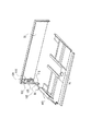
【図3】本発明の実施形態に係る画像形成装置に用いた給紙カセットの背面上方から見た斜視図である。
【図4】本発明の実施形態に係る画像形成装置に用いた給紙カセットの位置制御機構を示す側面図である。
【図5】本発明の実施形態に係る給紙カセットを主要部を背面方向から見た斜視図である。
【図6】本発明の実施形態に係る給紙カセットを主要部を正面方向から見た斜視図である。
【図7】本発明の実施形態に係る給紙カセットのシート残量表示機構を示す斜視図である。
【図8】本発明の実施形態に係る給紙カセットのシート残量表示機構の連結部を示す断面図である。
【図9】本発明の実施形態に係る給紙カセットのシート残量表示機構のシート残量表示部を示す正面図である。
【符号の説明】
10 画像形成装置
12 画像形成装置本体
14 像形成手段
18 給紙ユニット
22 給紙カセット
32 主枠体
34 補助枠体
72 正面カバー部
76 シート積載板
92 シート残量表示機構
94 シート残量検出部
96 連結部
100 第1の回動軸
102 第2の回動軸
114 防護部
116 シート残量表示部
118 窓部
120 表示片
122 カム
126 レバー[0001]
TECHNICAL FIELD OF THE INVENTION
The present invention relates to a sheet feeding cassette for storing sheets and an image forming apparatus such as an electrophotographic type having the sheet feeding cassette.
[0002]
2. Description of the Related Art As a paper feed cassette of an image forming apparatus, a main frame and an auxiliary frame slidably provided on the main frame are provided. It is known to expand and contract (see Patent Document 1). There is also known a device having a sheet remaining amount mechanism that detects the remaining amount of sheets in a sheet feeding cassette and displays the remaining amount of sheets on the sheet feeding cassette (see Patent Documents 2 and 3).
[0003]
[Patent Document 1]
JP-A-5-51136 [Patent Document 1]
JP-A-6-271141 [Patent Document 1]
JP-A-10-194479
[Problems to be solved by the invention]
However, conventionally, there is no known sheet cassette in which a sheet remaining amount display mechanism is applied to a retractable sheet cassette. Since the conventional sheet remaining amount display mechanism is configured to move the remaining amount display unit connected to the sheet stacking plate for stacking sheets, if this is applied to a flexible paper cassette, the sheet stacking plate is It is inevitable to provide a remaining sheet display section on the provided main frame. When the paper feed cassette is mounted on the image forming apparatus, when the auxiliary frame is located on the front side and the main frame is located on the back side, the main frame is provided with a sheet remaining amount display unit. And it is difficult to check the remaining amount of sheets.
SUMMARY OF THE INVENTION It is an object of the present invention to provide a paper cassette capable of easily confirming the remaining amount of sheets in a telescopic paper cassette and an image forming apparatus having the same.
[0006]
Means for Solving the Problems To achieve the above object, a first feature of the present invention is that a main frame and an auxiliary frame slidably provided on the main frame. A sheet remaining amount detecting unit that moves in accordance with the remaining amount of stacked sheets, a connecting unit that is connected to the sheet remaining amount detecting unit, and that moves in accordance with sliding of the auxiliary frame, and a movement of the connecting unit. And a sheet remaining amount display unit for displaying a sheet remaining amount on the auxiliary frame according to the above. Therefore, since the remaining sheet display portion can be provided on the auxiliary frame, the remaining sheet can be easily confirmed even when the main frame is disposed on the back side.
It is preferable that a sheet stacking plate for stacking sheets is provided on the main frame, and a connecting portion is connected to the sheet stacking plate. The sheet stacking plate is provided with a mechanism such as rotating, tilting, and vertically moving according to the remaining amount of the sheet. The movement of the sheet stacking plate can be detected by the sheet remaining amount detecting unit. In this case, the sheet remaining amount detecting unit is rotated according to the remaining sheet amount, and the rotation of the sheet detecting unit can be transmitted to the sheet remaining amount display unit via the connecting unit. It is preferable that a lever is provided on one of the connecting portion and the remaining sheet amount display portion and a cam is provided on the other, and the rotation of the connecting portion is converted into a vertical movement of a display piece provided on the remaining sheet amount displaying portion.
It is preferable that the position of the connecting portion is fixed so that only the rotation is allowed by the supporting portion provided on the auxiliary frame. When the auxiliary frame is extended, there is a possibility that the user may come into direct contact with the connecting portion. Therefore, it is preferable to provide a protective portion. The protection part can be configured as a protection wall formed in an eave shape and provided on the connection part and a protection cover surrounding the connection part.
According to a second feature of the present invention, an image forming apparatus main body, image forming means housed in the image forming apparatus main body, and a paper feed cassette for storing sheets to be conveyed to the image forming means are provided. The paper cassette includes a main frame, an auxiliary frame slidably provided with respect to the main frame, and a remaining sheet detecting unit that moves in accordance with the remaining amount of stacked sheets. A connecting portion connected to the remaining sheet detecting section and moving in accordance with the sliding of the auxiliary frame; and a remaining sheet amount displaying the remaining sheet on the auxiliary frame in accordance with the movement of the connecting portion. A display unit, wherein at least a part of the auxiliary frame protrudes forward from the image forming apparatus main body when the auxiliary frame is extended. As described above, since the auxiliary frame of the paper feed cassette is configured to be able to protrude from the image forming apparatus main body, when storing small-sized sheets in the paper feed cassette, the paper feed cassette is contracted to reduce the entire image forming apparatus. The sheet can be made compact, and large-sized sheets can be stored by extending the sheet feeding cassette. In addition, even when the sheet cassette is expanded or contracted in this manner, the remaining sheet amount can be confirmed by the remaining sheet display portion provided on the auxiliary frame.
[0010]
Embodiments of the present invention will now be described with reference to the drawings.
FIG. 1 shows an outline of an
Each
At least one of the plurality of
The
Accordingly, the sheet conveyed from the
However, in the case of double-sided printing, it is returned to the reversing path. That is, the front of the
The
The
The
2 and 3, an example of the
The
This control mechanism may be constituted by an electric mechanism for electrically detecting the position of the above-mentioned
In FIG. 4, the
When the
As described above, the
5 to 9, a sheet remaining
The connecting
Above the connecting
The sheet remaining
The
Next, the operation of the above embodiment will be described.
The
On the other hand, one of the
When the recording medium is guided between the
In the
When the
The mechanism for displaying the remaining amount of sheets in the above-described embodiment is merely an example, and may be any mechanism that supports expansion and contraction of the
[0035]
As described above, according to the present invention, in the extensible paper cassette, the remaining sheet amount is detected via the connecting portion which expands and contracts in conjunction with the sliding of the auxiliary frame with respect to the main frame. Since the unit and the remaining sheet display unit are connected, the remaining sheet display unit can be provided on the auxiliary frame, so that the remaining sheet can be easily checked.
[Brief description of the drawings]
FIG. 1 is a cross-sectional view illustrating an image forming apparatus according to an embodiment of the present invention.
FIG. 2 is a perspective view of the sheet cassette used in the image forming apparatus according to the embodiment of the present invention, as viewed from the front upper side.
FIG. 3 is a perspective view of the sheet cassette used in the image forming apparatus according to the embodiment of the present invention, as viewed from the upper rear side.
FIG. 4 is a side view illustrating a position control mechanism of a sheet cassette used in the image forming apparatus according to the embodiment of the present disclosure.
FIG. 5 is a perspective view of a main part of the paper feed cassette according to the embodiment of the present invention, as viewed from the back.
FIG. 6 is a perspective view of a main portion of the sheet cassette according to the embodiment of the present invention, as viewed from the front.
FIG. 7 is a perspective view showing a sheet remaining amount display mechanism of the sheet cassette according to the embodiment of the present invention.
FIG. 8 is a cross-sectional view showing a connection portion of a sheet remaining amount display mechanism of the sheet cassette according to the embodiment of the present invention.
FIG. 9 is a front view showing a sheet remaining amount display unit of the sheet remaining amount display mechanism of the sheet cassette according to the embodiment of the present invention.
[Explanation of symbols]
10
Claims (9)
Priority Applications (3)
| Application Number | Priority Date | Filing Date | Title |
|---|---|---|---|
| JP2002270052A JP3952500B2 (en) | 2002-09-17 | 2002-09-17 | Paper feeding cassette and image forming apparatus |
| US10/383,248 US6869071B2 (en) | 2002-09-17 | 2003-03-07 | Sheet supply cassette and image forming apparatus |
| CNB031197396A CN100378597C (en) | 2002-09-17 | 2003-03-10 | Paper Feeder and Imaging Unit |
Applications Claiming Priority (1)
| Application Number | Priority Date | Filing Date | Title |
|---|---|---|---|
| JP2002270052A JP3952500B2 (en) | 2002-09-17 | 2002-09-17 | Paper feeding cassette and image forming apparatus |
Publications (2)
| Publication Number | Publication Date |
|---|---|
| JP2004106983A true JP2004106983A (en) | 2004-04-08 |
| JP3952500B2 JP3952500B2 (en) | 2007-08-01 |
Family
ID=31986837
Family Applications (1)
| Application Number | Title | Priority Date | Filing Date |
|---|---|---|---|
| JP2002270052A Expired - Fee Related JP3952500B2 (en) | 2002-09-17 | 2002-09-17 | Paper feeding cassette and image forming apparatus |
Country Status (3)
| Country | Link |
|---|---|
| US (1) | US6869071B2 (en) |
| JP (1) | JP3952500B2 (en) |
| CN (1) | CN100378597C (en) |
Cited By (4)
| Publication number | Priority date | Publication date | Assignee | Title |
|---|---|---|---|---|
| JP2012197129A (en) * | 2011-03-18 | 2012-10-18 | Seiko Epson Corp | Recording material feed cassette and recording apparatus |
| JP2017013973A (en) * | 2015-07-02 | 2017-01-19 | キヤノン株式会社 | Sheet loading apparatus |
| JP2020117404A (en) * | 2015-07-02 | 2020-08-06 | キヤノン株式会社 | Sheet loading apparatus |
| JP2020193090A (en) * | 2019-05-29 | 2020-12-03 | 株式会社リコー | Image forming device |
Families Citing this family (20)
| Publication number | Priority date | Publication date | Assignee | Title |
|---|---|---|---|---|
| JP4204990B2 (en) * | 2003-03-31 | 2009-01-07 | 株式会社リコー | Feeding apparatus and image forming apparatus |
| US7258338B2 (en) * | 2004-06-03 | 2007-08-21 | Hewlett-Packard Development Company, L.P. | Media tray for image forming devices |
| JP2006058944A (en) * | 2004-08-17 | 2006-03-02 | Canon Inc | Image forming system and image forming apparatus |
| US20060244203A1 (en) * | 2005-04-28 | 2006-11-02 | Hewlett-Packard Development Company, Lp | Media tray |
| JP4641503B2 (en) * | 2006-02-03 | 2011-03-02 | キヤノン株式会社 | Sheet feeding apparatus and image forming apparatus |
| US20090206544A1 (en) * | 2008-02-18 | 2009-08-20 | Xerox Corporation | Preventing Overfill Of Media Sheets In a Sheet Feeder |
| JP5135390B2 (en) * | 2010-06-30 | 2013-02-06 | 京セラドキュメントソリューションズ株式会社 | Paper remaining amount detection device, image forming device |
| TW201300248A (en) * | 2011-06-29 | 2013-01-01 | Hon Hai Prec Ind Co Ltd | Printer capable of indicating amount of remaining papers |
| JP2013129487A (en) * | 2011-12-21 | 2013-07-04 | Ricoh Co Ltd | Remaining paper amount display device and image forming device |
| JP5880841B2 (en) * | 2012-03-01 | 2016-03-09 | 株式会社リコー | Feeding apparatus and image forming apparatus |
| CN102785952A (en) * | 2012-08-20 | 2012-11-21 | 天津光电通信技术有限公司 | Paper bin structure for left-side feeding of office equipment |
| JP2014148400A (en) * | 2013-02-01 | 2014-08-21 | Konica Minolta Inc | Paper feeder and image forming apparatus |
| JP6388159B2 (en) * | 2014-11-14 | 2018-09-12 | 富士ゼロックス株式会社 | Image forming apparatus |
| US10730709B2 (en) * | 2015-09-11 | 2020-08-04 | Hewlett-Packard Development Company, L.P. | Media tray assemblies with indicators |
| US10960604B2 (en) * | 2015-12-04 | 2021-03-30 | Hewlett-Packard Development Company, L.P. | Indicators |
| TWI666129B (en) * | 2017-01-12 | 2019-07-21 | 虹光精密工業股份有限公司 | Tray drawer and multi-function printer using the same |
| CN107298324A (en) * | 2017-06-27 | 2017-10-27 | 莫佩行 | Printer paper fixing device |
| CN108328370A (en) * | 2018-03-29 | 2018-07-27 | 上海富士施乐有限公司 | Paper-advance unit and image processing equipment for image processing equipment |
| JP7161345B2 (en) * | 2018-08-29 | 2022-10-26 | シャープ株式会社 | Paper feeder and image forming device |
| CN109051239B (en) * | 2018-09-10 | 2023-09-05 | 江苏德尔森汽车有限公司 | A storage device for sorting parts of hydraulic booster pump assembly |
Family Cites Families (8)
| Publication number | Priority date | Publication date | Assignee | Title |
|---|---|---|---|---|
| US5172903A (en) * | 1990-09-28 | 1992-12-22 | Konica Corporation | Paper feed cassette |
| JPH0551136A (en) | 1991-08-22 | 1993-03-02 | Brother Ind Ltd | Paper feed cassette device in image forming device |
| JP2840517B2 (en) * | 1992-06-02 | 1998-12-24 | キヤノン株式会社 | Paper cassette and image forming apparatus |
| JPH06271141A (en) | 1993-03-19 | 1994-09-27 | Ricoh Co Ltd | Residual paper quantity indicator for paper feeding cassette |
| KR0141668B1 (en) * | 1994-09-27 | 1998-07-01 | 김광호 | Device for measuring the number of paper for a printer |
| JPH10194479A (en) | 1996-12-27 | 1998-07-28 | Canon Inc | Sheet loading device, image recording device, and facsimile device |
| JP3740278B2 (en) * | 1998-04-15 | 2006-02-01 | 株式会社リコー | Paper cassette |
| US6206362B1 (en) * | 1999-08-31 | 2001-03-27 | Hewlett-Packard Company | Media stack status indicator |
-
2002
- 2002-09-17 JP JP2002270052A patent/JP3952500B2/en not_active Expired - Fee Related
-
2003
- 2003-03-07 US US10/383,248 patent/US6869071B2/en not_active Expired - Lifetime
- 2003-03-10 CN CNB031197396A patent/CN100378597C/en not_active Expired - Lifetime
Cited By (6)
| Publication number | Priority date | Publication date | Assignee | Title |
|---|---|---|---|---|
| JP2012197129A (en) * | 2011-03-18 | 2012-10-18 | Seiko Epson Corp | Recording material feed cassette and recording apparatus |
| JP2017013973A (en) * | 2015-07-02 | 2017-01-19 | キヤノン株式会社 | Sheet loading apparatus |
| US9857748B2 (en) | 2015-07-02 | 2018-01-02 | Canon Kabushiki Kaisha | Sheet supporting device |
| JP2020117404A (en) * | 2015-07-02 | 2020-08-06 | キヤノン株式会社 | Sheet loading apparatus |
| JP2020193090A (en) * | 2019-05-29 | 2020-12-03 | 株式会社リコー | Image forming device |
| JP7261390B2 (en) | 2019-05-29 | 2023-04-20 | 株式会社リコー | image forming device |
Also Published As
| Publication number | Publication date |
|---|---|
| JP3952500B2 (en) | 2007-08-01 |
| US20040051231A1 (en) | 2004-03-18 |
| CN100378597C (en) | 2008-04-02 |
| US6869071B2 (en) | 2005-03-22 |
| CN1484113A (en) | 2004-03-24 |
Similar Documents
| Publication | Publication Date | Title |
|---|---|---|
| JP2004106983A (en) | Sheet feeding cassette and image formation device | |
| JP6732548B2 (en) | Sheet ejection device and image forming apparatus | |
| JP6236789B2 (en) | Paper feeding device and image forming apparatus having the same | |
| US7413188B2 (en) | Paper feed cassette, recording medium size detector and image formation device using coaxial movable members for moving orthogonal fences | |
| JP5129285B2 (en) | Paper feeding device and image forming apparatus | |
| JP2001122447A (en) | Sheet feeding apparatus and image forming apparatus | |
| JP6204248B2 (en) | Operation panel support mechanism and image forming apparatus having the same | |
| US7484730B2 (en) | Image forming apparatus | |
| JPH11180602A (en) | Sheet material loading tray mechanism and image formation device | |
| JP5948301B2 (en) | Recording medium storage device and image forming apparatus having the same | |
| JP4402451B2 (en) | Image forming apparatus | |
| JP3149307B2 (en) | Cassette with paper size detector | |
| JP3774533B2 (en) | Sheet storage device and image processing device | |
| JP5025019B2 (en) | Image forming apparatus | |
| JP3915908B2 (en) | Paper cassette | |
| JP2004107009A (en) | Paper feeding cassette | |
| US20070104530A1 (en) | Image forming apparatus having unit housing permitting mechanism | |
| JP3611539B2 (en) | Image forming apparatus | |
| JP3483319B2 (en) | Sheet feeding apparatus and image forming apparatus | |
| JP7446160B2 (en) | Media transport device | |
| JP2004107042A (en) | Sheet carrier device, paper feeding unit, and image forming device | |
| JP2009040542A (en) | Paper feeder and image forming device | |
| JP2008120485A (en) | Image forming device | |
| JP3604671B2 (en) | Image forming device | |
| JP3622531B2 (en) | Sheet feeding device |
Legal Events
| Date | Code | Title | Description |
|---|---|---|---|
| A621 | Written request for application examination |
Free format text: JAPANESE INTERMEDIATE CODE: A621 Effective date: 20050818 |
|
| A871 | Explanation of circumstances concerning accelerated examination |
Free format text: JAPANESE INTERMEDIATE CODE: A871 Effective date: 20060811 |
|
| A975 | Report on accelerated examination |
Free format text: JAPANESE INTERMEDIATE CODE: A971005 Effective date: 20060927 |
|
| A131 | Notification of reasons for refusal |
Free format text: JAPANESE INTERMEDIATE CODE: A131 Effective date: 20061018 |
|
| A521 | Request for written amendment filed |
Free format text: JAPANESE INTERMEDIATE CODE: A523 Effective date: 20061212 |
|
| A521 | Request for written amendment filed |
Free format text: JAPANESE INTERMEDIATE CODE: A523 Effective date: 20061212 |
|
| A131 | Notification of reasons for refusal |
Free format text: JAPANESE INTERMEDIATE CODE: A131 Effective date: 20070117 |
|
| A521 | Request for written amendment filed |
Free format text: JAPANESE INTERMEDIATE CODE: A523 Effective date: 20070314 |
|
| TRDD | Decision of grant or rejection written | ||
| A01 | Written decision to grant a patent or to grant a registration (utility model) |
Free format text: JAPANESE INTERMEDIATE CODE: A01 Effective date: 20070409 |
|
| A61 | First payment of annual fees (during grant procedure) |
Free format text: JAPANESE INTERMEDIATE CODE: A61 Effective date: 20070422 |
|
| R150 | Certificate of patent or registration of utility model |
Free format text: JAPANESE INTERMEDIATE CODE: R150 |
|
| FPAY | Renewal fee payment (event date is renewal date of database) |
Free format text: PAYMENT UNTIL: 20110511 Year of fee payment: 4 |
|
| FPAY | Renewal fee payment (event date is renewal date of database) |
Free format text: PAYMENT UNTIL: 20110511 Year of fee payment: 4 |
|
| FPAY | Renewal fee payment (event date is renewal date of database) |
Free format text: PAYMENT UNTIL: 20120511 Year of fee payment: 5 |
|
| FPAY | Renewal fee payment (event date is renewal date of database) |
Free format text: PAYMENT UNTIL: 20130511 Year of fee payment: 6 |
|
| FPAY | Renewal fee payment (event date is renewal date of database) |
Free format text: PAYMENT UNTIL: 20130511 Year of fee payment: 6 |
|
| FPAY | Renewal fee payment (event date is renewal date of database) |
Free format text: PAYMENT UNTIL: 20140511 Year of fee payment: 7 |
|
| LAPS | Cancellation because of no payment of annual fees |