【0001】
【発明の属する技術分野】
本発明は収納棚間を走行するスタッカークレーンを備える自動倉庫に関し、特には作業効率を向上させる技術に関する。
【0002】
【従来の技術】
従来の自動倉庫としては、対向配置された収納棚間に1台のスタッカークレーンを配し、このスタッカークレーンにより収納棚への入出庫作業を行うようにしたものが知られているが、より効率的に作業を行うために、例えば同一レール上を複数台のスタッカークレーンが走行するようにしたものや、収納棚の両側にそれぞれ1台ずつスタッカークレーンを有するもの等が提案されている(下記文献参照)。尚、同一レール上を複数台(例えば2台)のスタッカークレーンが走行する場合には、スタッカークレーン同士が衝突や追突を起こす危険性があることから、例えば下記文献に示すように、自車、他車それぞれの位置情報に基づいて走行を制御し衝突や追突を未然に防ぐことなどが行われている。
【0003】
又、作業の効率化を図るための別法として、収納棚の奥行方向に複数の物品を収納するようにし、多段階に進退動作するスライドフォークにて入出庫作業を行うようにした自動倉庫なども提案されている(下記文献参照)。
【0004】
【文献1】特開平10−152207号公報(第2頁、図1)
【文献2】実開平5−46805号公報(第4頁、図1)
【文献3】特許第2857836号公報(第2−4頁、図1−3)
【文献4】特開昭62−157102号公報(第3頁、図6−9)
【0005】
【発明が解決しようとする課題】
同一レール上を複数台のスタッカークレーンが走行するよう構成する場合には、入出庫ステーションを複数箇所に設けたり、入出庫ステーションが収納棚の一方にのみ設けられている自動倉庫では、スタッカークレーンとは別の搬送装置(レール台車)を設けたりしなければ作業効率を高めることができないため、実施する上での制約が大きいという問題がある。
【0006】
収納棚の両側をそれぞれ1台ずつのスタッカークレーンが走行するよう構成する場合には、入出庫ステーションが収納棚の一方にのみ設けられている自動倉庫であっても実施可能であるが、例えば左右一対の収納棚を有する自動倉庫では3台のスタッカークレーンを設置することになり、自動倉庫の収容効率が大幅に低下するという問題がある。
【0007】
本発明は、上記従来の技術の課題を解決するためのものであり、大幅な収容効率の低下を招くことなく容易に実施可能であり、且つ効率的な入出庫作業が行える構成とされた自動倉庫を提供することを目的とする。
【0008】
【課題を解決するための手段】
上記の目的を達成するため、本発明は、左右一対の収納棚間に、該収納棚と並行して複数列の走行レールが設けられると共に、各走行レール上に少なくとも1台のスタッカークレーンが備えられており、各スタッカークレーンには、左右の収納棚との間で物品の入出庫を行う、左右方向に進退動作可能なスライドフォークが設けられていることを特徴とする自動倉庫とする、という技術的手段を採用する。
【0009】
本発明によれば、複数列の走行レール上を走行する複数台のスタッカークレーンにより左右の収納棚への入出庫作業を行うことができるため、スタッカークレーンの台数に応じて搬送量が増大することになり、入出庫作業の効率を向上させることが可能となる。又、入出庫位置が収納棚の両端に配されている場合は勿論のこと、収納棚の一端のみに配されている場合にも適用でき、上記の優れた効果を得ることができる。但し、各走行レール上複数台のスタッカークレーンを備える構成とする際には、入出庫位置を収納棚の複数箇所に配することが好ましい。又更に、本発明によれば、上記の通り作業効率を高めながら、収納棚の両側にスタッカークレーンを設置する場合に比べ収容効率の低下を抑えることができるという効果が得られる。
【0010】
本発明において、収納棚が、スタッカークレーン側列と反スタッカークレーン側列の左右2列からなると共に、収納棚間には2列の走行レールが設けられている場合には、各走行レール上を走行するスタッカークレーンに、該スタッカークレーンが走行する走行レールに近い側の収納棚のスタッカークレーン側列と反スタッカークレーン側列とに入出庫可能であり、且つ遠い側の収納棚のスタッカークレーン側列に入出庫可能とされた、左右方向に進退動作するスライドフォークを設けるようにすることができる。
【0011】
このようにすれば、例えば左の収納棚に対し左のスタッカークレーンが入出庫を行っている最中に、右のスタッカークレーンにより左の収納棚のスタッカークレーン側列への入出庫を行うといったことが可能であり、入出庫作業の効率をすこぶる高めることができる。
【0012】
又、本発明において、各走行レール上を走行するスタッカークレーンの位置を検出する位置検出手段と、スライドフォークの作動状態を検出する状態検出手段と、位置検出手段及び状態検出手段の検出結果に基づきスタッカークレーンの走行を制御する走行制御手段と、を備え、走行制御手段が、隣り合う走行レール上のスタッカークレーンのそれぞれの位置から両スタッカークレーンの車間距離を導出すると共に、該車間距離が所定値以下であり、且つスライドフォークが車間距離導出の対象となるスタッカークレーン側へ進出している場合には、両スタッカークレーンが互いに近づく向きの走行を禁止する制御を行うようにすることができる。
【0013】
このようにすれば、隣り合う走行レール上のスタッカークレーン同士が衝突することを防止でき、安全に入出庫作業を行うことができる。ここで所定値は、例えばブレーキ装置によりスタッカークレーンを急停車させるために必要な制動距離よりも若干大きな値と設定することができ、又、スタッカークレーンの走行速度に応じて異なる値と設定することもできる。尚、スタッカークレーンの走行速度に応じて異なるよう設定された所定値に基づいた走行制御とすれば、必要以上に車間距離が確保されることがなくなるので、作業効率の低下を防止することができる。
【0014】
【発明の実施の形態】
以下、本発明の実施の形態について、図面に参照して詳細に説明する。尚、図1は本実施形態に係る自動倉庫の斜視図、図2は本実施形態に係るスタッカークレーンの斜視図、図3は本実施形態に係る自動倉庫の要部の機能ブロック図であり、図4は本実施形態に係る自動倉庫の制御フロー図である。又、図5及び図6は本実施形態に係る自動倉庫の稼動状況を示す概略平面図である。
【0015】
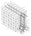
図1に示すように、本実施形態に係る自動倉庫は、物品を収納する収納部を上下方向、及び前後方向にそれぞれ多数備えた左右1対の収納棚1,2と、これら収納棚1,2の間に、収納棚1,2に並行して前後方向に設けられた走行レール10,20と、各走行レール上を走行するスタッカークレーン11,21とを備え、このスタッカクレーン11,21によって、収納棚1,2の前後方向一端側に設けられた左右1対の入出庫ステーション3,4と、収納棚1,2との間の物品の搬送が行われるようになっている。
【0016】
収納棚1(2)は、スタッカークレーン側列1a(2a)と反スタッカークレーン側列1b(2b)との左右2列の収納部を備えており、いずれの収納部もスタッカークレーン11,21の少なくとも一方による物品の入出庫が行えるよう、スタッカークレーン側に開口されて形成されている。尚、この実施例では、収納棚1,2のスタッカークレーン側列1a,2aの一端側に入出庫ステーション3,4が併設されているが、収納棚1,2の両端側に入出庫ステーションを設けるようにしても構わない。
【0017】
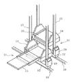
図2に示すように、スタッカークレーン11,21は、それぞれ主に走行レール10,20上を前後方向に走行するための台車12,22と、台車12,22に立設されたマスト13,23と、マスト13,23に案内されて上下方向に昇降自在とされた、物品を載置させるキャリッジ14,24とからなり、各キャリッジ14,24には、収納棚1,2の収納部、及び入出庫ステーション3,4との間で物品を受け渡しするための左右方向に進退動作可能なスライドフォーク15,25が備えられている。台車12,22には車輪を回転駆動させる走行モータ及びこの走行用モータに制動をかけるブレーキ装置を有する走行駆動装置16,26、及び昇降用モータを有する昇降駆動装置17,27が搭載され、キャリッジ14,24にはスライド用モータを有する進退駆動装置18,28が搭載されており、台車12,22には更にこれら各駆動装置を制御する制御装置19,29が搭載されている。そして、制御装置19,29により、走行駆動装置16,26が制御されて台車12,22は走行し、昇降駆動装置17,27が制御されてキャリッジ14,24は昇降し、進退駆動装置18,28が制御されてスライドフォーク15,25は進退する。
【0018】
ここで、スタッカークレーン11のスライドフォーク15は2段階に進退する構造とされており、スタッカークレーン11に近い側の収納棚である収納棚1のスタッカークレーン側列1a及び反スタッカークレーン側列1bの収納部と、スタッカークレーン11から遠い側の収納棚である収納棚2のスタッカークレーン側列2aの収納部と、入出庫ステーション3,4との間で物品の受け渡しが可能である。又、スタッカークレーン21のスライドフォーク25も同様に2段階に進退する構造とされており、スタッカークレーン21に近い側の収納棚である収納棚2のスタッカークレーン側列2a及び反スタッカークレーン側列2bの収納部と、スタッカークレーン21から遠い側の収納棚である収納棚1のスタッカークレーン側列1aの収納部と、入出庫ステーション3,4との間で物品の受け渡しが可能である。
【0019】
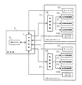
図3は本実施形態に係る自動倉庫の要部の機能ブロック図であり、この図3に示すように、上記スタッカクレーン11,21の台車12,22の走行、キャリッジ14,24の昇降、及びスライドフォーク15,25の進退動作は管理機5によって一括的に制御されるようになっており、管理機5からの動作指令信号が各スタッカークレーン11,21に搭載された制御装置19,29へと送信されると共に、各制御装置19,29が上記指令信号に基づいてスタッカークレーン11,21が備える走行駆動装置16,26、昇降駆動装置17,27、及び進退駆動装置18,28を制御する。又、台車12,22には、台車12,22に備えられた車輪の回転数を検出するエンコーダE1,E2がそれぞれ設けられ、またキャリッジ14,24には各スライドフォーク15,25が隣りのスタッカークレーン側へと進出するとオンされるようマイクロスイッチSW1,SW2がそれぞれ設けられおり、これらの検出信号が管理機5へ送信されるようになっている。尚、このようなマイクロスイッチSW1,SW2が、本発明におけるフォーク状態検出手段に相当する。
【0020】
管理機5は、作業者が入出庫の指示を行うために操作する操作パネル6と、操作パネル6によって入力される信号とエンコーダE1,E2及びマイクロスイッチSW1,SW2からの検出信号とに従って、以下に詳述する処理を行い動作指令信号を送信する演算装置7とを備えている。そして、作業者が操作パネル6を操作して、入庫/出庫と、入庫である場合には入出庫ステーション3,4のいすれから収納棚1,2の何処に物品を入庫するか、出庫である場合には収納棚1,2の何処に収納されている物品を入出庫ステーション3,4のいすれに出庫するか、といった指示を入力すると、この入力に従って、演算装置7が各スタッカークレーン11,21をどのように動作させるかを表す動作指令信号を各スタッカークレーン11,21へ送信する。尚、一連の入出庫作業が完了すると、演算装置7は各スタッカークレーン11,21へホームポジション、すなわち入出庫ステーション3,4の側方の待機位置に移動するよう動作指令信号を送信し、スタッカークレーン11,21をこのホームポジションで次の入出庫作業まで待機させるようになっている。
【0021】
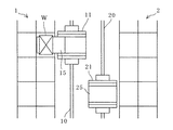
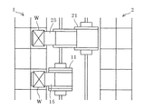
次に、本実施形態に係る両スタッカークレーンの衝突を回避するための制御について、図4に示す制御フロー図並びに図5ないし図7に示す自動倉庫の稼動状況を示す概略平面図を参照して説明する。尚、説明上、スタッカークレーンが上記ホームポジションから遠ざかる方向をスタッカークレーンの前進方向、ホームポジションへ近付く方向を後進方向とする。
【0022】
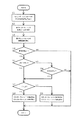
管理機5の演算装置7は、先ずエンコーダE1,E2及びマイクロスイッチSW1,SW2からの検出信号を取込み(S1)、エンコーダE1,E2の検出信号に基づいて、各スタッカークレーン11,21のホームポジションを基準とした走行レール10,20上の位置L1,L2をそれぞれ導出し(S2)、導出した各位置から前後方向に両スタッカークレーン11,21が離間している距離(車間距離)を導出する(S3)。具体的には、演算装置7は、エンコーダE1,E2からの検出信号として入力される車輪の回転数に車輪の径を乗算して走行距離を求め、この走行距離を累算することによりホームポジションからの距離、つまり現在の位置を導出する。このような演算装置7による演算処理、並びに車輪の回転数を検出するエンコーダE1,E2により、本発明における位置検出手段が構成されている。そして、演算装置7は、各スタッカークレーン11,21のホームポジションからの距離の差を求めることで、両スタッカークレーン11,21の前後方向の車間距離を導出する。
【0023】
続いて、演算装置7は、導出された両スタッカークレーン11,21の車間距離が所定値L以下であるか否かを判断する(S4)。ここで所定値Lを、例えばブレーキ装置によりスタッカークレーンを急停車させるために必要な制動距離よりも若干大きな値と設定しておけば、車間距離が所定値L以下となった時点でブレーキ装置にて制動をかければ、衝突することなくスタッカークレーンを停車させることができることになる。S4において、両スタッカークレーン11,21の車間距離が所定値Lよりも大きいと判断されれば(S4のNO)、両スタッカークレーン11,21が衝突する恐れはないので、走行を禁止させることはせず、両スタッカークレーン11,21とも前後いずれの方向にも走行可能である。S4において、両スタッカークレーン11,21の車間距離が所定値L以下であると判断されれば(S4のYES)、マイクロスイッチSW1,SW2のいずれかがオンであるか否かが判断される(S5,S6)。
【0024】
マイクロスイッチSW1,SW2のいずれもオンではないと判断されれば(S5のNO,S6のNO)、両スタッカークレーン11,21が衝突する恐れはないので、走行を禁止させることはせず、両スタッカークレーン11,21とも前後いずれの方向にも走行可能である。すなわち、例えば図5に示すように、スタッカークレーン11が停車しスタッカークレーン21とは反対側の収納棚1へスライドフォーク15を進出させて物品Wの入庫/出庫作業を行っている場合には、スタッカークレーン21をスタッカークレーン11へ近付くようと前進、或いは後進させることができる。スタッカークレーン11の横を通過させることもできるので、例えば図6に示すように、スタッカークレーン11が入出庫作業を行っている位置よりも更に前方位置でスタッカークレーン21を停車させ、収納棚1へスライドフォーク25を進出させて物品Wの入庫/出庫作業を行うことが可能である。又、スタッカークレーン11の横でスタッカークレーン21を停車させ、収納棚2へスライドフォーク25を進出させて入出庫作業を行うこともできる。
【0025】
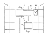
マイクロスイッチSW1,SW2のいずれか一方がオンであると判断されれば(S5のYES,S6のYES)、両スタッカークレーン11,21の位置L1,L2が比較される(S7)。スタッカークレーン11の位置L1がスタッカークレーン21の位置L2よりも遠ければ(S7のYES)、演算装置7は、両スタッカークレーンが互いに近付く向きの走行、すなわちスタッカークレーン11の後進とスタッカークレーン21の前進とを禁止する旨の指令信号を制御装置19,29へと送信する。そして、この指令信号に従って、制御装置19は走行駆動装置16がスタッカークレーン11を後進させるよう作動することを禁止し、制御装置29は走行駆動装置26がスタッカークレーン21を前進させるよう作動することを禁止する(S8)。走行駆動装置16が既にスタッカークレーン11を後進させるよう作動している、或いは走行駆動装置26が既にスタッカークレーン21を前進させるよう作動しているときには、制御装置19,29は各走行駆動装置が備えるブレーキ装置を作動させて、走行を停止させる。例えば図7に示すように、スタッカークレーン11が停車しスタッカークレーン21側の収納棚2へスライドフォーク15を進出させて物品Wの入庫/出庫作業を行っている場合には、スタッカークレーン21がスタッカークレーン11へと前進することが禁止され、仮にスタッカークレーン21が走行中であったとしても停車させられるので、両スタッカークレーン11,21の衝突が未然に防止される。又、スタッカークレーン11がスタッカークレーン21へと後進することも禁止されるので、上記のようにして停車したスタッカークレーン21に対しスライドフォーク15がキャリッジ14へ完全に収納されていない状態のスタッカークレーン11が衝突することも防止される。
【0026】
又、スタッカークレーン11の位置L1がスタッカークレーン21の位置L2よりも近ければ(S7のNO)、演算装置7は、両スタッカークレーンが互いに近付く向きの走行、すなわちスタッカークレーン11の前進とスタッカークレーン21の後進とを禁止する旨の指令信号を制御装置19,29へと送信する。そして、この指令信号に従って、制御装置19は走行駆動装置16がスタッカークレーン11を前進させるよう作動することを禁止し、制御装置29は走行駆動装置26がスタッカークレーン21を後進させるよう作動することを禁止する(S9)。走行駆動装置16が既にスタッカークレーン11を前進させるよう作動している、或いは走行駆動装置26が既にスタッカークレーン21を後進させるよう作動しているときには、制御装置19,29は各走行駆動装置が備えるブレーキ装置を作動させて、走行を停止させる。尚、以上で説明した演算装置7による車間距離の導出処理、並びに演算装置7、制御装置19,29によるスタッカークレーンの走行禁止に係る処理が、本発明における走行制御手段に相当する。
【0027】
このように、本実施形態によれば、2台のスタッカークレーン11,21により同時的に入出庫作業を行うことが可能であることから、スタッカークレーンが1台のみである場合よりも搬送量が増大し、入出庫作業の効率がすこぶる向上することとなると共に、両スタッカークレーン11,21が衝突することなく走行するよう制御されるので、安全に入出庫作業を行うことができる。しかも、2台のスタッカークレーン11,21は並走するように構成されていることから、入出庫ステーション3,4が収納棚1,2にのみ設けられている場合でも充分に作業効率が高められる。又、本実施形態では、収納棚1に2列(1a,1b)、収納棚2に2列(2a,2b)の計4列の収納部に対し、2列、各1台のスタッカークレーン11,21で物品の搬送を行うようにしているので、スタッカークレーンが2列で配設されることによる自動倉庫の収容効率の低下が抑えられている。
【0028】
本実施形態によれば、更に、左右一対の入出庫ステーション3,4が設けられていることから両入出庫ステーション3,4から同時に物品を入庫させたり、同時に物品を出庫させたり、一方で入庫し他方で出庫するといったことを同時に行わせたりすることができる。又、スタッカークレーン11と右の入出庫ステーション4、或いは右の収納棚2のスタッカークレーン側列2aとの間で物品の受け渡しをさせたり、スタッカークレーン21と左の入出庫ステーション3、或いは左の収納棚1のスタッカークレーン側列1aとの間で物品の受け渡しをさせたりすることができるので、極めて自由度の高い入出庫作業が可能であり、作業者は適切な方法(例えば、入出庫作業の所要時間が最小となる方法)で自動倉庫を運用することができる。
【0029】
【発明の効果】
本発明によれば、複数台のスタッカークレーンにより入出庫作業が行えることから、入出庫作業の効率をすこぶる高めることができ、しかも安全に自動倉庫を運用することが可能となる。
【図面の簡単な説明】
【図1】本発明に係る自動倉庫の斜視図である。
【図2】本発明に係るスタッカークレーンの斜視図である。
【図3】本発明に係る自動倉庫の要部の機能ブロック図である。
【図4】本発明に係る自動倉庫の制御フロー図である。
【図5】本発明に係る自動倉庫の稼動状況を示す概略平面図である。
【図6】本発明に係る自動倉庫の稼動状況を示す概略平面図である。
【図7】本発明に係る自動倉庫の稼動状況を示す概略平面図である。
【符号の説明】
1、2 収納棚
3、4 入出庫ステーション
5 管理機
10、20 走行レール
11、21 スタッカークレーン
15、25 スライドフォーク
19、29 制御装置
E1、E2 エンコーダ
SW1、SW2 マイクロスイッチ[0001]
TECHNICAL FIELD OF THE INVENTION
The present invention relates to an automatic warehouse having a stacker crane running between storage shelves, and more particularly to a technique for improving work efficiency.
[0002]
[Prior art]
As a conventional automatic warehouse, there is known an automatic warehouse in which one stacker crane is arranged between storage shelves arranged opposite to each other, and the stacker crane is used to perform a work of moving in and out of the storage shelves. In order to perform the work efficiently, for example, a system in which a plurality of stacker cranes run on the same rail, a system having one stacker crane on each side of a storage shelf, and the like have been proposed (see the following document). reference). When a plurality of (for example, two) stacker cranes travel on the same rail, there is a risk that the stacker cranes collide with each other or cause a rear-end collision. BACKGROUND ART Travel is controlled based on the position information of each other vehicle to prevent a collision or a rear-end collision.
[0003]
In addition, as an alternative method of improving work efficiency, an automatic warehouse that stores a plurality of articles in the depth direction of a storage shelf and performs loading / unloading work with a slide fork that moves in and out of multiple stages. Have also been proposed (see the following literature).
[0004]
[Document 1] Japanese Patent Application Laid-Open No. 10-152207 (page 2, FIG. 1)
[Reference 2] Japanese Utility Model Laid-Open No. 5-46805 (page 4, FIG. 1)
[Reference 3] Japanese Patent No. 2857836 (pages 2-4, FIG. 1-3)
Reference 4: Japanese Patent Application Laid-Open No. Sho 62-157102 (page 3, FIG. 6-9)
[0005]
[Problems to be solved by the invention]
When a plurality of stacker cranes are configured to run on the same rail, an entry / exit station may be provided at a plurality of locations. However, there is a problem in that the work efficiency cannot be improved unless another transfer device (rail carriage) is provided, so that there is a great restriction in implementing the method.
[0006]
When one stacker crane runs on each side of the storage shelf, it can be implemented even in an automatic warehouse in which the entry / exit station is provided on only one of the storage shelves. In an automatic warehouse having a pair of storage shelves, three stacker cranes are installed, and there is a problem that the storage efficiency of the automatic warehouse is greatly reduced.
[0007]
An object of the present invention is to solve the above-mentioned problems of the conventional technology, and can be easily implemented without causing a large decrease in storage efficiency, and is configured so as to enable efficient entry / exit operations. The purpose is to provide a warehouse.
[0008]
[Means for Solving the Problems]
In order to achieve the above object, the present invention provides a plurality of traveling rails between a pair of left and right storage shelves in parallel with the storage shelves, and at least one stacker crane provided on each traveling rail. Each stacker crane is provided with a slide fork that can move in and out of the left and right storage shelves that can move goods in and out of the left and right storage shelves. Adopt technical means.
[0009]
According to the present invention, since a plurality of stacker cranes traveling on a plurality of rows of traveling rails can be used to enter and exit the left and right storage shelves, the transport amount increases according to the number of stacker cranes. It becomes possible to improve the efficiency of loading and unloading work. Further, the present invention can be applied not only to the case where the loading / unloading position is arranged at both ends of the storage shelf but also to the case where it is arranged only at one end of the storage shelf, and the above-mentioned excellent effects can be obtained. However, when a plurality of stacker cranes are provided on each traveling rail, it is preferable to arrange the loading / unloading positions at a plurality of locations on the storage shelf. Further, according to the present invention, it is possible to obtain the effect that the lowering of the storage efficiency can be suppressed as compared with the case where stacker cranes are installed on both sides of the storage shelf, while increasing the work efficiency as described above.
[0010]
In the present invention, when the storage shelves are composed of two left and right rows of a stacker crane side row and an anti-stacker crane side row, and two rows of travel rails are provided between the storage shelves, The traveling stacker crane can enter and exit the stacker crane side row and the anti-stacker crane side row of the storage shelf on the side near the traveling rail on which the stacker crane travels, and the stacker crane side row of the storage shelf on the far side. A slide fork that can be moved in and out of the vehicle and that moves forward and backward in the left-right direction can be provided.
[0011]
In this way, for example, while the left stacker crane is moving in and out of the left storage shelf, the right stacker crane moves in and out of the left storage shelf to the stacker crane side row. Is possible, and the efficiency of the loading / unloading operation can be significantly improved.
[0012]
Further, in the present invention, a position detecting means for detecting a position of the stacker crane traveling on each traveling rail, a state detecting means for detecting an operation state of the slide fork, and a detection result of the position detecting means and the state detecting means. Traveling control means for controlling traveling of the stacker crane, wherein the traveling control means derives an inter-vehicle distance between the two stacker cranes from respective positions of the stacker cranes on adjacent traveling rails, and the inter-vehicle distance is a predetermined value. In the following, when the slide fork has advanced to the side of the stacker crane that is the target of deriving the inter-vehicle distance, control can be performed to prohibit the two stacker cranes from traveling in a direction approaching each other.
[0013]
With this configuration, it is possible to prevent the stacker cranes on the adjacent traveling rails from colliding with each other, and it is possible to safely perform the loading / unloading operation. Here, the predetermined value can be set to a value slightly larger than the braking distance required for stopping the stacker crane suddenly by the brake device, for example, or can be set to a different value according to the traveling speed of the stacker crane. it can. If the traveling control is performed based on a predetermined value that is set differently according to the traveling speed of the stacker crane, the inter-vehicle distance is not secured more than necessary, so that a decrease in work efficiency can be prevented. .
[0014]
BEST MODE FOR CARRYING OUT THE INVENTION
Hereinafter, embodiments of the present invention will be described in detail with reference to the drawings. 1 is a perspective view of the automatic warehouse according to the present embodiment, FIG. 2 is a perspective view of the stacker crane according to the present embodiment, and FIG. 3 is a functional block diagram of a main part of the automatic warehouse according to the present embodiment. FIG. 4 is a control flowchart of the automatic warehouse according to the present embodiment. FIGS. 5 and 6 are schematic plan views showing the operation status of the automatic warehouse according to the present embodiment.
[0015]
As shown in FIG. 1, the automatic warehouse according to the present embodiment includes a pair of left and right storage shelves 1 and 2 provided with a large number of storage units for storing articles in a vertical direction and a front and rear direction, respectively. 2, traveling rails 10 and 20 provided in the front-rear direction in parallel with the storage shelves 1 and 2 and stacker cranes 11 and 21 traveling on each traveling rail are provided. Articles are transported between the storage shelves 1 and 2 and a pair of left and right entry / exit stations 3 and 4 provided at one end in the front-rear direction of the storage shelves 1 and 2.
[0016]
The storage shelves 1 (2) are provided with two left and right storage sections of a stacker crane side row 1a (2a) and an anti-stacker crane side row 1b (2b). The opening is formed on the stacker crane side so that at least one of the articles can be loaded and unloaded. In this embodiment, the loading and unloading stations 3 and 4 are provided at one end of the stacker crane side rows 1a and 2a of the storage shelves 1 and 2, respectively. It may be provided.
[0017]
As shown in FIG. 2, the stacker cranes 11 and 21 mainly include trucks 12 and 22 for traveling on traveling rails 10 and 20, respectively, and masts 13 and 23 erected on the trucks 12 and 22. And carriages 14 and 24 on which articles are placed, which are guided vertically by the masts 13 and 23 so as to be able to move up and down. The carriages 14 and 24 have storage sections of the storage shelves 1 and 2, and Slide forks 15 and 25 are provided which can move forward and backward in the left and right direction for transferring articles to and from the loading and unloading stations 3 and 4. The carriages 12 and 22 are equipped with traveling motors 16 and 26 having traveling motors for rotating and driving wheels and braking devices for braking the traveling motors, and elevation driving devices 17 and 27 having elevator motors. Forward and backward drive units 18 and 28 having slide motors are mounted on 14 and 24, and control units 19 and 29 for controlling these drive units are further mounted on the carts 12 and 22, respectively. Then, the traveling drives 16 and 26 are controlled by the controllers 19 and 29, and the carriages 12 and 22 travel, and the lift drives 17 and 27 are controlled to move the carriages 14 and 24 up and down. 28 is controlled, and the slide forks 15, 25 advance and retreat.
[0018]
Here, the slide fork 15 of the stacker crane 11 is configured to advance and retreat in two stages, and the stacker crane side row 1a and the anti-stacker crane side row 1b of the storage shelf 1 which is the storage shelf on the side close to the stacker crane 11 are arranged. It is possible to transfer articles between the storage section, the storage section of the stacker crane side row 2a of the storage shelf 2 which is a storage shelf far from the stacker crane 11, and the loading / unloading stations 3 and 4. Similarly, the slide fork 25 of the stacker crane 21 is configured to advance and retreat in two stages, and the stacker crane side row 2a and the anti-stacker crane side row 2b of the storage shelf 2 which is a storage shelf close to the stacker crane 21. Can be transferred between the storage section of the stacker crane 21, the storage section of the stacker crane side row 1 a of the storage shelf 1 which is the storage shelf far from the stacker crane 21, and the loading / unloading stations 3 and 4.
[0019]
FIG. 3 is a functional block diagram of a main part of the automatic warehouse according to the present embodiment. As shown in FIG. 3, the carriages 12 and 22 of the stacker cranes 11 and 21 travel, the carriages 14 and 24 move up and down, and The forward and backward movements of the slide forks 15 and 25 are controlled collectively by the management machine 5, and operation command signals from the management machine 5 are sent to the control devices 19 and 29 mounted on each of the stacker cranes 11 and 21. And the control devices 19 and 29 control the traveling drive devices 16 and 26, the elevation drive devices 17 and 27, and the forward / backward drive devices 18 and 28 of the stacker cranes 11 and 21 based on the command signal. . Further, the carriages 12 and 22 are provided with encoders E1 and E2 for detecting the number of rotations of the wheels provided on the carriages 12 and 22, respectively. Micro switches SW1 and SW2 are provided so as to be turned on when the vehicle advances to the crane side, and these detection signals are transmitted to the management machine 5. Note that such micro switches SW1 and SW2 correspond to fork state detecting means in the present invention.
[0020]
The management machine 5 performs the following operations in accordance with an operation panel 6 operated by the operator to issue a loading / unloading instruction, a signal input by the operation panel 6 and detection signals from the encoders E1 and E2 and the micro switches SW1 and SW2. And an arithmetic unit 7 for performing the processing described in detail above and transmitting an operation command signal. Then, the operator operates the operation panel 6 to enter / exit from the storage shelves 1 and 2 from either the entry / exit station 3 or 4 in the case of the entry / exit and the entry / exit. In some cases, when an instruction such as where the articles stored in the storage shelves 1 and 2 should be taken out of the entry / exit stations 3 and 4 is input, the arithmetic unit 7 causes the stacker cranes 11 according to the input. , 21 are transmitted to each of the stacker cranes 11 and 21. When a series of loading / unloading operations is completed, the arithmetic unit 7 sends an operation command signal to each of the stacker cranes 11 and 21 to move to a home position, that is, a standby position beside the loading / unloading stations 3 and 4, The cranes 11 and 21 are made to wait at the home position until the next loading / unloading operation.
[0021]
Next, control for avoiding collision between the two stacker cranes according to the present embodiment will be described with reference to a control flow diagram shown in FIG. 4 and a schematic plan view showing an operation state of the automatic warehouse shown in FIGS. explain. In the description, the direction in which the stacker crane moves away from the home position is referred to as the forward direction of the stacker crane, and the direction in which the stacker crane approaches the home position is the reverse direction.
[0022]
The arithmetic unit 7 of the management machine 5 first takes in the detection signals from the encoders E1 and E2 and the micro switches SW1 and SW2 (S1), and based on the detection signals of the encoders E1 and E2, the home position of each stacker crane 11 and 21. The positions L1 and L2 on the traveling rails 10 and 20 are derived respectively with reference to (S2), and the distance (inter-vehicle distance) between the two stacker cranes 11 and 21 in the front-rear direction from each derived position is derived. (S3). Specifically, the arithmetic unit 7 obtains the traveling distance by multiplying the rotation number of the wheel, which is input as the detection signal from the encoders E1 and E2, by the diameter of the wheel, and accumulates the traveling distance to obtain the home position. Derived the distance from, that is, the current position. The arithmetic processing by the arithmetic unit 7 and the encoders E1 and E2 for detecting the number of rotations of the wheels constitute a position detecting means in the present invention. Then, the arithmetic unit 7 derives the inter-vehicle distance in the front-rear direction of the two stacker cranes 11 and 21 by obtaining the difference between the distances of the respective stacker cranes 11 and 21 from the home position.
[0023]
Subsequently, the arithmetic unit 7 determines whether or not the derived inter-vehicle distance between the two stacker cranes 11 and 21 is equal to or less than a predetermined value L (S4). Here, if the predetermined value L is set to a value slightly larger than the braking distance required for stopping the stacker crane suddenly by the braking device, for example, the braking device is used when the inter-vehicle distance becomes the predetermined value L or less. If braking is applied, the stacker crane can be stopped without collision. If it is determined in S4 that the inter-vehicle distance between the two stacker cranes 11 and 21 is larger than the predetermined value L (NO in S4), there is no possibility that the two stacker cranes 11 and 21 will collide with each other, so that traveling is prohibited. Instead, both stacker cranes 11 and 21 can travel in both front and rear directions. In S4, if it is determined that the inter-vehicle distance between the two stacker cranes 11 and 21 is equal to or less than the predetermined value L (YES in S4), it is determined whether one of the micro switches SW1 and SW2 is on (S4). S5, S6).
[0024]
If it is determined that neither of the micro switches SW1 and SW2 is turned on (NO in S5, NO in S6), there is no danger that the two stacker cranes 11 and 21 will collide with each other. Both the stacker cranes 11 and 21 can travel in any direction. That is, for example, as shown in FIG. 5, when the stacker crane 11 stops and the slide fork 15 advances to the storage shelf 1 on the opposite side of the stacker crane 21 to perform the entry / exit work of the article W, The stacker crane 21 can move forward or backward so as to approach the stacker crane 11. Because the stacker crane 11 can pass beside the stacker crane 11, the stacker crane 21 is stopped at a position further forward than the position where the stacker crane 11 is performing the loading and unloading work, and is moved to the storage shelf 1 as shown in FIG. The entry / exit operation of the article W can be performed by advancing the slide fork 25. Alternatively, the stacker crane 21 can be stopped next to the stacker crane 11 and the slide fork 25 can be advanced to the storage shelf 2 to perform a loading / unloading operation.
[0025]
If it is determined that one of the micro switches SW1 and SW2 is ON (YES in S5, YES in S6), the positions L1 and L2 of both stacker cranes 11 and 21 are compared (S7). If the position L1 of the stacker crane 11 is farther than the position L2 of the stacker crane 21 (YES in S7), the arithmetic unit 7 travels in a direction in which both stacker cranes approach each other, that is, the backward movement of the stacker crane 11 and the advance of the stacker crane 21 Are transmitted to the control devices 19 and 29 to prohibit the above. Then, in accordance with this command signal, the control device 19 prohibits the traveling drive device 16 from operating to move the stacker crane 11 backward, and the control device 29 causes the traveling drive device 26 to operate to advance the stacker crane 21 forward. It is prohibited (S8). When the traveling drive device 16 is already operating to move the stacker crane 11 backward, or when the traveling drive device 26 is already operating to advance the stacker crane 21, the control devices 19 and 29 are provided in each traveling drive device. Activate the brake device to stop traveling. For example, as shown in FIG. 7, when the stacker crane 11 is stopped and the slide fork 15 is advanced to the storage shelf 2 on the side of the stacker crane 21 to perform the loading / unloading operation of the articles W, the stacker crane 21 is moved to the stacker. The forward movement to the crane 11 is prohibited, and the vehicle is stopped even if the stacker crane 21 is running, so that the collision between the two stacker cranes 11 and 21 is prevented. Further, the backward movement of the stacker crane 11 to the stacker crane 21 is also prohibited, so that the stacker crane 11 in a state where the slide fork 15 is not completely housed in the carriage 14 with respect to the stacker crane 21 stopped as described above. Are also prevented from colliding.
[0026]
On the other hand, if the position L1 of the stacker crane 11 is closer than the position L2 of the stacker crane 21 (NO in S7), the arithmetic unit 7 travels in a direction in which both stacker cranes approach each other, that is, the advance of the stacker crane 11 and the stacker crane 21 Is transmitted to the control devices 19 and 29 to prohibit the backward movement. Then, in accordance with this command signal, the control device 19 inhibits the traveling drive device 16 from operating to move the stacker crane 11 forward, and the control device 29 causes the traveling drive device 26 to operate to move the stacker crane 21 backward. It is prohibited (S9). When the traveling drive 16 is already operating to move the stacker crane 11 forward, or when the traveling drive 26 is already operating to move the stacker crane 21 backward, the controllers 19 and 29 are provided in each traveling drive. Activate the brake device to stop traveling. The process for deriving the inter-vehicle distance by the arithmetic unit 7 and the process for prohibiting the traveling of the stacker crane by the arithmetic unit 7 and the control devices 19 and 29 correspond to the travel control means in the present invention.
[0027]
As described above, according to the present embodiment, the loading and unloading work can be performed simultaneously by the two stacker cranes 11 and 21, so that the transport amount is smaller than when only one stacker crane is used. The stacking cranes 11 and 21 are controlled so as to travel without collision, so that the warehousing operation can be performed safely. In addition, since the two stacker cranes 11 and 21 are configured to run in parallel, the work efficiency can be sufficiently improved even when the loading / unloading stations 3 and 4 are provided only in the storage shelves 1 and 2. . In the present embodiment, two rows (1a, 1b) of the storage shelves 1 and two rows (2a, 2b) of the storage shelves 2 for a total of four rows of storage units, one for each stacker crane 11 are provided. , 21 are used to convey articles, so that a reduction in the storage efficiency of the automatic warehouse due to the arrangement of the stacker cranes in two rows is suppressed.
[0028]
According to the present embodiment, since a pair of left and right entry / exit stations 3 and 4 are further provided, articles can be entered from both entry / exit stations 3 and 4 at the same time, articles can be exited at the same time, or entered at the same time. Then, it is possible to simultaneously carry out the retrieval on the other side. In addition, articles are transferred between the stacker crane 11 and the right entry / exit station 4 or the stacker crane side row 2a of the right storage shelf 2, or the stacker crane 21 and the left entry / exit station 3 or the left Since goods can be transferred to and from the stacker crane side row 1a of the storage shelf 1, it is possible to perform a very high degree of freedom in entering / exiting work, and a worker can use an appropriate method (for example, entering / exiting work). Method that minimizes the required time).
[0029]
【The invention's effect】
ADVANTAGE OF THE INVENTION According to this invention, since a warehouse operation | work can be performed by a several stacker crane, the efficiency of a warehouse operation can be improved very much, and also an automatic warehouse can be operated safely.
[Brief description of the drawings]
FIG. 1 is a perspective view of an automatic warehouse according to the present invention.
FIG. 2 is a perspective view of a stacker crane according to the present invention.
FIG. 3 is a functional block diagram of a main part of the automatic warehouse according to the present invention.
FIG. 4 is a control flowchart of the automatic warehouse according to the present invention.
FIG. 5 is a schematic plan view showing the operation status of the automatic warehouse according to the present invention.
FIG. 6 is a schematic plan view showing the operation status of the automatic warehouse according to the present invention.
FIG. 7 is a schematic plan view showing the operation status of the automatic warehouse according to the present invention.
[Explanation of symbols]
1, 2 Storage shelf 3, 4 Entry / exit station 5 Management machine 10, 20 Running rail 11, 21 Stacker crane 15, 25 Slide fork 19, 29 Control device E1, E2 Encoder SW1, SW2 Micro switch