JP2004106008A - Welding joint and welding method thereof - Google Patents
Welding joint and welding method thereof Download PDFInfo
- Publication number
- JP2004106008A JP2004106008A JP2002270982A JP2002270982A JP2004106008A JP 2004106008 A JP2004106008 A JP 2004106008A JP 2002270982 A JP2002270982 A JP 2002270982A JP 2002270982 A JP2002270982 A JP 2002270982A JP 2004106008 A JP2004106008 A JP 2004106008A
- Authority
- JP
- Japan
- Prior art keywords
- welding
- base material
- current
- groove
- welding wire
- Prior art date
- Legal status (The legal status is an assumption and is not a legal conclusion. Google has not performed a legal analysis and makes no representation as to the accuracy of the status listed.)
- Pending
Links
Images


Abstract
Description
【0001】
【発明の属する技術分野】
本発明は、溶接継手及びその溶接方法に係り、更に詳しくは厚肉部材のT字形の溶接継手及びその溶接方法に関するものである。
【0002】
【従来の技術】
建築物の鉄骨構造、橋梁、産業機械、建設機械等のあらゆる溶接構造物においては、溶接継手としてT字形継手を採用する場合が多い。このT字形継手の溶接手法としては、種々の溶接方法があるが、その一つの溶接方法として、T字形継手において、レ形の開先を有する一方の部材を、他方の部材に突合せ、前記レ形の開先側から溶接を行い、開先の裏側に裏波ビードを形成するものがある。この溶接方法は、前述した開先側の部分を溶融させ、この溶融プールを開先側から開先裏側に押し出すものであり、BOB(Bulldozed−Out Bead)溶接方法と称している(非特許文献1参照。)。
【0003】
【非特許文献1】
高谷 透、他3名、「T継手における裏波ビード溶接方法の研究」(社)溶接学会、第175回溶接法資料、第143回アーク物理資料、2001年8月8日
【0004】
【発明が解決しようとする課題】
前述した従来技術は、裏当て材を使用せずに、開先の裏側に裏波ビードを形成することができるので、箱形などの閉断面構造や狭隘部のT字形継手の溶接に有効な溶接方法である。この溶接方法は、本件出願の発明者等によって開発研究されているものであるが、この溶接方法の前述した利点を活用し、種々の肉厚を有する部材への適用を試みているが、特に、T字形継手を構成する部材の肉厚が厚い場合、一方の部材に設けたレ形の開先から溶接を行っても、この一方の部材と他方の部材とが突き合わされた部分における他方の部材の溶け込みが十分になされないため、未溶着部が発生するという問題があった。
【0005】
本発明は、上述の事柄にもとづいてなされたもので、厚肉部材の溶接接合を可能にした溶接継手及びその溶接方法を提供することを目的とする。
【0006】
【課題を解決するための手段】
本発明の目的を達成するために、第1の発明は、第1の母材の面と第2の母材の端面との当接部を突合せ溶接する溶接継手において、前記第2の母材における当接部の一方側に形成した第1の開先に臨ませた溶接ワイヤのアークにより、前記当接部を溶融させ、この溶融物を溶接側とは反対側に押し出して形成した第1の溶接部と、前記第2の母材における当接部の他方側に形成した第2の開先に臨ませた溶接ワイヤのアークにより、前記第2の開先側の当接部及び前記第1の溶接部の一部を溶融させて溶接する第2の溶接部とで、前記第1の母材と第2の母材との当接部を突合せ溶接したことを特徴する溶接継手にある。
【0007】
また、第2の発明は、第1の発明において、前記第1の母材と第2の母材とは、厚肉部材であることを特徴とする溶接継手にある。
【0008】
更に、第3の発明は、第1または第の発明において、前記第1の溶接部を形成するための溶接ワイヤへの印加電流は、直流電流とパルス状の電流とを重畳させた電流であり、前記第2の溶接部を形成するための溶接ワイヤへの印加電流は、直流電流であることを特徴とする溶接継手にある。
【0009】
また、第4の発明は、第1の母材の面と第2の母材の端面との当接部を突合せ溶接する溶接継手の溶接方法において、前記第2の母材における当接部の一方側に形成した第1の開先に、溶接ワイヤを臨ませ、この溶接ワイヤのアークにより、前記当接部を溶融させ、この溶融物を溶接側とは反対側に押し出して第1の溶接部を形成し、次に、前記第2の母材における当接部の他方側に形成した第2の開先に、溶接ワイヤを臨ませ、この溶接ワイヤのアークにより、前記第2の開先側の当接部及び前記第1の溶接部の一部を溶融させて第2の溶接部を形成し、前記第1の母材と第2の母材との当接部を突合せ溶接したことを特徴する溶接継手の溶接方法にある。
【0010】
更に、第5発明は、第3の発明において、前記第1の母材と第2の母材とは、厚肉部材であることを特徴とする溶接継手の溶接方法にある。
【0011】
また、第6の発明は、第4または第5の発明において、前記第1の溶接部を形成するための溶接ワイヤへの印加電流は、直流電流とパルス状の電流とを重畳させた電流であり、前記第2の溶接部を形成するための溶接ワイヤへの印加電流は、直流電流であることを特徴とする溶接継手の溶接方法にある。
【0012】
【発明の実施の形態】
以下、本発明の溶接継手及びその製造方法の実施の形態を、図面を用いて説明する。
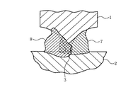
図1は、本発明の溶接継手の一実施の形態を示す断面図で、この図において、1は第1の母材、2はこの第1の母材1に接合される第2の母材である。前述した第1の母材1は、その突合わせ端部にルートフェイス3を有するようにその一方側に形成した第1のレ型開先形成面4と他方側に形成した第2のレ型開先形成面5が設けられている。また、前述した第2の母材2は第1の母材1のルートフェイス3と接触する平坦面6を有しており、第1の母材1とによりT字形継手を形成する。
【0013】
7は第1の溶接部で、この第1の溶接部7は第1の母材1における第1のレ型開先形成面4と第2の母材2の平坦面7とにより形成される第1の開先に設けられている。この第1の溶接部7は後述する溶接ワイヤからのアークによって、第1の開先側の部分を溶融した溶融物を第1の開先側から第2の開先側に押し出すようにして形成されている。8は第2の溶接部で、この第2の溶接部8は後述する溶接ワイヤからのアークによって、第2の開先側の部分及び前記第1の溶接部の一部を溶融させて形成されている。
【0014】
前述した第1の溶接部7を形成するために、溶接ワイヤには、直流電流とパルス状の電流とを重畳させた電流が印加される。また、第2の溶接部8を形成するために、溶接ワイヤには、直流電流が印加される。
【0015】
図2は、本発明の継手の製作に用いる溶接装置の一実施の形態の構成を示すもので、この図2において、図1に示す符号と同符号のものは、同一部分を示す。10は旋回可能なロボット本体、11はロボット本体10に設けた平行リンク部、12は平行リンク部11に設けたロボットアーム、13はロボットアーム12の先端に設けた溶接トーチ、14は溶接トーチ13に保持された溶接ワイヤ、15は溶接ワイヤ14を溶接トーチ13を介して送給するための送給装置である。
【0016】
16はロボット制御装置で、このロボット制御装置16は指令信号を出力してロボットアーム12を図に示す少なくとも互いに直交するX、Y、Zの3軸方向に駆動制御する。また、ロボット制御装置16は、種々の制御設定値等を入力・記憶するための入力部17 と、ロボットアーム12の位置・姿勢制御のための位置制御部18と、溶接速度を制御するための速度制御部19等とから構成されている。
【0017】
20および21は溶接電力を供給するためのケーブルで、その一方はロボットに備えられた送給装置15側で溶接ワイヤ14に、他方は溶接すべき第1の母材1または第2の母材2に接続されている。
【0018】
22は溶接電源で、この溶接電源22はケーブル20および21により溶接ワイヤ14と母材1または2に接続されている。23は電圧検出器で、この電圧検出器23は溶接電源22から溶接ワイヤ14に供給される溶接電流の電圧を検出する。24は電流検出器で、この電流検出器24は溶接電源22から溶接ワイヤ14に供給される溶接電流を検出する。
【0019】
25は平均電圧設定器で、この平均電圧設定器25は溶接ワイヤ14に供給すべき平均電圧値を設定する。26は電圧制御器で、この電圧制御器26は平均電圧設定器25に設定された平均電圧と電圧検出器23で検出された電圧が後述の電力診断部を介して入力された実平均電圧値とを比較して、電圧制御信号を出力する。
【0020】
27は平均電流設定器で、この平均電流設定器27は溶接ワイヤ14に供給すべき平均電流値を設定する。28は電流制御器で、この電流制御器28は平均電圧設定器27に設定された平均電流と電流検出器24で検出された電流が後述の電力診断部を介して入力された実平均電流値とを比較して、電流制御信号を出力する。
【0021】
29は出力制御器で、この出力制御器29は電圧制御器26からの電圧制御信号と電流制御器28からの電流制御信号が入力され、それらの制御信号に基づいて、溶接電源22から供給されるべき電力を制御するための制御信号を出力する。
【0022】
30は電力診断装置で、この電力診断装置30は入力部31と、比較部32と、出力部33とから構成されている。入力部31は、平均電圧設定器25で設定される平均電圧より高い電圧の第1の電圧設定値と平均電圧設定器25で設定される平均電圧より低い電圧の第2の電圧設定値や、平均電流設定器27で設定される平均電流より高い電流の電流設定値を設定する。
【0023】
比較部32は、電圧検出器23から入力される実電圧値と前記第1および第2の電圧設定値とを比較し、後述の位置制御信号をロボット制御装置16に出力するとともに、電流検出器24から入力される実電流値と前記電流設定値とを比較し、位置制御信号をロボット制御装置16に出力する機能を備えている。
【0024】
出力部33は、電圧検出器23や電流検出器24から検出された実電圧値および実電流値をそれぞれ電圧制御器26および電流制御器28に出力する機能をする。
【0025】
そして、上述した溶接装置は、上記各制御装置やロボット等のこれら全体を制御するコンピュータ等により構成されている。
【0026】
次に、上述したアーク溶接装置を用いて本発明の継手の一実施の形態の溶接接合する方法を説明する。
【0027】
図2において、溶接トーチ14はロボットアーム12に取り付けられており、溶接ワイヤ14は溶接トーチ13に保持されながら溶接トーチ13の先端より所定の長さ突き出ており、ワイヤ送給装置15によって送られるようになっている。そこで、この図2に示すように、溶接ワイヤ14は第1の開先側に所定の傾斜角度δ傾けられて、かつ所定の狙い位置に向けて対向される。この位置設定はロボット制御装置16の入力部17および位置制御部18によって行われる。また、移動経路や溶接速度は入力部17から速度制御部19に与えられ、それに基づいて、溶接ワイヤ14は図2の図面上垂直方向に移動させられる。
【0028】
また、電力診断装置30の入力部31からは、予め第1および第2の電圧設定値と電流設定値が入力され、比較部32に記憶される。
【0029】
このように設定した状態で、初層のアーク溶接を開始する。溶接が始まると、電圧検出器23および電流検出器24はそれぞれケーブル20,21の実電圧値および実電流値を検出する。溶接中にロボットの振動や母材の位置ずれなどで溶接ワイヤ14が例えば母材1の開先側に寄りすぎると、熱容量の小さい開先の端部が溶け落ちてしまい溶接ビードを置くことができなくなる。端部が溶け落ちるとアークが母材の裏に抜けてしまい、実電圧値が高くなる。すると、電力診断装置30の比較部32では予め入力された第1および第2の電圧設定値と実電圧値とが比較され、実電圧値が第1の電圧設定値を超えると、溶接ワイヤ14を第2の母材2側に移動するように位置制御信号をロボット10の位置制御部18に出力し、溶接ワイヤ14は第1の母材1の第1の開先側から第2の母材2側に近づくように移動修正される。
【0030】
これとは反対に、溶接ワイヤ14と母材との相対的位置関係が設定位置に対し第2の母材2側に寄ってしまった場合、開先側への入熱が少なくなり溶接ビードが第2の開先側に押し出されなくなり、手前側にビードが溜まってくる。すると、溶接ワイヤ14の突き出し長さが短くなるので、実電圧値は下がり実電流値は高くなる現象が起こる。
【0031】
したがって、比較部32は予め入力されている電圧設定値と実電圧値を比較し、実電圧値が第2の電圧設定値を下回ったとき、溶接ワイヤ14を開先側に移動するように位置制御信号を位置制御部18に指令し、溶接ワイヤ14は開先側に移動修正させられる。
【0032】
あるいは、電流検出器24によって実電流値が検出されているので、比較器32は予め入力されている電流設定値と実電流値を比較し、実電流値が電流設定値を超えた場合、溶接ワイヤ14を開先側に移動するように位置制御信号を位置制御部18に指令し、溶接ワイヤ14は開先側に移動修正させるようにしてもよい。
【0033】
一方、電力診断装置30の出力部33は、電圧検出器23および電流検出器24から検出された実電圧値および実電流値を、それぞれ電圧制御器26および電流制御器28に出力する。
【0034】
電圧制御器26では、予め設定されている平均電圧値と実電圧値を比較し、実電圧値が平均電圧になるように電圧制御指令信号を出力制御部29に出力する。また、電流制御器28は、予め設定されている平均電流値と実電流値を比較し、実電流値が平均電流になるように電流制御指令信号を出力制御部29に出力する。
【0035】
出力制御部29は、入力された電圧制御指令信号と電流制御指令信号に基づいて、溶接電源22から供給する電圧と電流を調整する制御信号を溶接電源22に出力し、供給電力が設定値になるように調整される。
【0036】
このように、溶接ワイヤ14と母材との位置関係を設定値に移動修正しながら、また平均電圧と平均電流も設定値になるように修正しながら溶接される。
【0037】
ここで、前述した第1の開先に第1の溶接部7を形成する方法を図3を用いて説明すると、図3に示すように溶接ワイヤ14の先端を、第1のレ形開形形成面4と第2の母材2の平坦面6とで形成された第1の開先内に位置させる。
【0038】
この状態において、前述した溶接装置の溶接電源22から、例えば溶接トーチ14と第2の母材2との間に、直流電流とパルス状の電流とを重畳した電流を印加すると、溶接ワイヤ14の先端からアークが発生する。このアークは第1の母材1と第2の母材2との当接部をバランス良く溶融するとともに、溶接ワイヤ14自身も溶融する。これにより、この部分に溶融物のプールが形成される。
【0039】
この溶融物のプールが増加すると、この溶融物はアークの噴出力や溶融物のプール内の対流などにより、第1の開先側から第2の開先側に押し出され、さらに表面張力などの働きにより、第1の開先内から第2の開先の一部部分まで一体となった溶融物のプールが形成され、それらが再凝固して図3に示すような第1の溶接部7がT字形継手における第1の開先の初層部として形成される。この第1の溶接部7は、図3の図面に垂直な方向に設けられて、溶接ビードを形成する。
【0040】
次に、第2の開先に第2の溶接部8を形成する場合を説明すると、前述した第1の開先への第1の溶接部7の形成と同様に、溶接ワイヤ14の先端を、図3の2点鎖線で示すように第2のレ形開形形成面5と第2の母材2の平坦面6とで形成された第2の開先内に位置させる。
【0041】
この状態において、前述した溶接装置の溶接電源22から、例えば溶接トーチ14と第2の母材2との間に、直流電流を印加すると、溶接ワイヤ14の先端からアークが発生する。このアークは第1の母材1と第2の母材2との当接部近傍および第1の溶接部7における第2の開先側への突出した部分等をバランス良く溶融する。これにより、第1の母材1と第2の母材2との当接部近傍および第1の溶接部7の一部の溶融物が一体となり、それらが再凝固して、図1に示すような第1の溶接部8がT字形継手における第2の開先の初層部として形成される。なお、上記の溶接状態は、開先部の初層の溶接であり、開先の大きさにもよるが開先部におけるその他残りの部分の溶接は従来と同様な方法で例えば多層の肉盛部を形成することができるので、その説明は省略する。
【0042】
図4は本発明の溶接継手の他の実施の形態を示すもので、この図4において、図1に示す符号と同符号のものは同一部分である。この実施の形態は、第1および第2のレ形開先形成面を、円弧面で構成ものである。この実施の形態においても、前述した実施の形態と同様に、堅固な結合を有する継手を得ることができる。
【0043】
なお、上述の実施の形態において、溶接トーチ14を直線移動させながら、溶接する場合を説明したが、この動作に加えて溶接トーチ14を揺動させることも可能である。また、上述の実施の形態においては、第の溶接部を形成するために、溶接トーチへの印加電流として、直流電流を用いたが、溶接溶け込みを良好にするために、パルス状の電流を用いることも可能である。
【0044】
【発明の効果】
以上に述べた如く、本発明の溶接継手によれば、第1の母材と第2の母材との突合せ部を、第1の溶接部と第2の溶接部との融合によって、未溶着部を生じることなく堅固に結合することができるので、この継手で接合構成された構造物の信頼性を向上させることができる。
【0045】
また、本発明の方法によれば、第1の母材と第の母材との当接部に形成される一方の開先に形成した第1の溶接部と、他方の開先に形成した第2の溶接部との溶融融合によって、前記当接部の接合を強度に維持することができる。
【図面の簡単な説明】
【図1】本発明の溶接継手の一実施の形態を示す溶接部の断面図である。
【図2】本発明の溶接継手の溶接に用いられる溶接装置の一例の構成図である。
【図3】本発明の溶接継手の一実施の形態における溶接部の形成過程を説明するための説明図である。
【図4】本発明の溶接継手の他の実施の形態を示す溶接部の断面図である。
【符号の説明】
1 第1の母材
2 第2の母材
3 ルートフェイス
4 第1の開先形成面
5 第2の開先形成面
7 第1の溶接部
8 第2の溶接部[0001]
TECHNICAL FIELD OF THE INVENTION
The present invention relates to a welded joint and a method for welding the same, and more particularly, to a T-shaped welded joint for a thick member and a method for welding the same.
[0002]
[Prior art]
In all welded structures such as steel structures of buildings, bridges, industrial machines, construction machines, etc., a T-shaped joint is often used as a weld joint. There are various welding methods for this T-shaped joint. One of the welding methods is to butt one member having a R-shaped groove to the other member in a T-shaped joint. In some cases, welding is performed from the groove side of the shape, and a back bead is formed on the back side of the groove. This welding method melts the above-described groove side portion and pushes out the molten pool from the groove side to the back side of the groove, and is referred to as a BOB (Bulldosed-Out Bead) welding method (Non-Patent Document) 1).
[0003]
[Non-patent document 1]
Toru Takatani and three others, "Study on Uranami Bead Welding Method for T Joints", Japan Welding Society, 175th welding method data, 143rd arc physics data, August 8, 2001 [0004]
[Problems to be solved by the invention]
The above-mentioned prior art can form a traverse bead on the back side of a groove without using a backing material, so that it is effective for welding a T-shaped joint having a closed section such as a box shape or a narrow portion. It is a welding method. This welding method has been developed and studied by the inventors of the present application, and attempts have been made to apply the method to members having various thicknesses by utilizing the aforementioned advantages of the welding method. When the thickness of the member constituting the T-shaped joint is large, even if welding is performed from the groove of the re-shaped portion provided on one member, the other member at the portion where the one member and the other member abut against each other is used. There is a problem that unwelded portions are generated because the members are not sufficiently melted.
[0005]
The present invention has been made based on the above-mentioned matters, and an object of the present invention is to provide a welded joint capable of welding and joining thick members and a welding method thereof.
[0006]
[Means for Solving the Problems]
In order to achieve the object of the present invention, a first invention provides a welded joint for butt-welding a contact portion between a surface of a first base material and an end surface of a second base material. The contact portion is melted by an arc of a welding wire facing a first groove formed on one side of the contact portion in the above, and the melt is extruded to a side opposite to the welding side to form a first portion. And the arc of the welding wire facing the second groove formed on the other side of the contact portion of the second base material, the contact portion on the second groove side and the second A welded joint, characterized in that a contact portion between the first base material and the second base material is butt-welded with a second welded portion for melting and welding a part of the first welded portion. .
[0007]
A second invention is the welded joint according to the first invention, wherein the first base material and the second base material are thick members.
[0008]
In a third aspect based on the first aspect, the current applied to the welding wire for forming the first weld is a current obtained by superimposing a DC current and a pulsed current. The current applied to the welding wire for forming the second weld is a direct current.
[0009]
Further, a fourth invention provides a welding method of a welding joint for butt-welding a contact portion between a surface of a first base material and an end surface of a second base material, wherein the contact portion of the second base material is A welding wire is made to face a first groove formed on one side, and the abutting portion is melted by an arc of the welding wire, and the molten material is extruded to a side opposite to the welding side to perform first welding. Forming a portion, and then facing the welding wire to a second groove formed on the other side of the contact portion of the second base material, and the arc of the welding wire causes the second groove to be formed. Forming a second welded portion by fusing the contact portion on the side and a part of the first welded portion, and butt-welding the contacted portion between the first base material and the second base material. A welding method for a welded joint characterized by the above.
[0010]
Furthermore, a fifth invention is the method for welding a weld joint according to the third invention, wherein the first base material and the second base material are thick members.
[0011]
In a sixth aspect based on the fourth or fifth aspect, the current applied to the welding wire for forming the first weld is a current obtained by superimposing a DC current and a pulsed current. The method for welding a weld joint according to
[0012]
BEST MODE FOR CARRYING OUT THE INVENTION
Hereinafter, embodiments of a welded joint and a method for manufacturing the same according to the present invention will be described with reference to the drawings.
FIG. 1 is a sectional view showing an embodiment of a welded joint according to the present invention. In this figure,
[0013]
[0014]
In order to form the first
[0015]
FIG. 2 shows a configuration of an embodiment of a welding apparatus used for manufacturing the joint of the present invention. In FIG. 2, the same reference numerals as those shown in FIG. 1 indicate the same parts.
[0016]
A
[0017]
[0018]
A
[0019]
An average
[0020]
An average
[0021]
[0022]
[0023]
The comparing
[0024]
The
[0025]
The above-described welding apparatus is configured by a computer or the like that controls the whole of the above-described control devices and robots.
[0026]
Next, a method for welding and joining the joint according to an embodiment of the present invention using the above-described arc welding apparatus will be described.
[0027]
In FIG. 2, a
[0028]
The first and second voltage set values and the current set values are input in advance from the
[0029]
In this state, arc welding of the first layer is started. When welding starts, the
[0030]
On the contrary, when the relative positional relationship between the
[0031]
Therefore, the
[0032]
Alternatively, since the actual current value is detected by the
[0033]
On the other hand, the
[0034]
The
[0035]
The
[0036]
In this manner, welding is performed while moving and correcting the positional relationship between the
[0037]
Here, a method of forming the first welded
[0038]
In this state, when a current obtained by superimposing a DC current and a pulsed current is applied between the
[0039]
When the pool of the melt increases, the melt is extruded from the first groove side to the second groove side due to the ejection power of the arc and the convection in the pool of the melt, and further, the surface tension and the like are increased. By operation, an integrated pool of melt is formed from within the first groove to a portion of the second groove, which resolidifies and forms a
[0040]
Next, a case in which the second welded
[0041]
In this state, when a direct current is applied from, for example, the
[0042]
FIG. 4 shows another embodiment of the welded joint according to the present invention. In FIG. 4, the same reference numerals as those shown in FIG. 1 denote the same parts. In this embodiment, the first and second groove-shaped forming surfaces are formed by arc surfaces. Also in this embodiment, a joint having a firm connection can be obtained as in the above-described embodiment.
[0043]
In the above-described embodiment, the case where welding is performed while the
[0044]
【The invention's effect】
As described above, according to the welded joint of the present invention, the butted portion of the first base material and the second base material is not welded by the fusion of the first welded portion and the second welded portion. Since the connection can be made firmly without any portion, the reliability of the structure joined and formed by this joint can be improved.
[0045]
Further, according to the method of the present invention, the first welded portion is formed at one groove formed at the contact portion between the first base material and the first base material, and is formed at the other groove formed at the other groove. The fusion of the contact portion with the second weld portion can maintain the strength of the joint.
[Brief description of the drawings]
FIG. 1 is a sectional view of a welded portion showing one embodiment of a welded joint of the present invention.
FIG. 2 is a configuration diagram of an example of a welding device used for welding a welded joint according to the present invention.
FIG. 3 is an explanatory diagram for explaining a process of forming a weld in one embodiment of the welded joint of the present invention.
FIG. 4 is a sectional view of a welded portion showing another embodiment of the welded joint of the present invention.
[Explanation of symbols]
DESCRIPTION OF
Claims (6)
Priority Applications (1)
| Application Number | Priority Date | Filing Date | Title |
|---|---|---|---|
| JP2002270982A JP2004106008A (en) | 2002-09-18 | 2002-09-18 | Welding joint and welding method thereof |
Applications Claiming Priority (1)
| Application Number | Priority Date | Filing Date | Title |
|---|---|---|---|
| JP2002270982A JP2004106008A (en) | 2002-09-18 | 2002-09-18 | Welding joint and welding method thereof |
Publications (2)
| Publication Number | Publication Date |
|---|---|
| JP2004106008A true JP2004106008A (en) | 2004-04-08 |
| JP2004106008A5 JP2004106008A5 (en) | 2005-09-08 |
Family
ID=32268428
Family Applications (1)
| Application Number | Title | Priority Date | Filing Date |
|---|---|---|---|
| JP2002270982A Pending JP2004106008A (en) | 2002-09-18 | 2002-09-18 | Welding joint and welding method thereof |
Country Status (1)
| Country | Link |
|---|---|
| JP (1) | JP2004106008A (en) |
Cited By (5)
| Publication number | Priority date | Publication date | Assignee | Title |
|---|---|---|---|---|
| JP2007090386A (en) * | 2005-09-29 | 2007-04-12 | Hitachi Ltd | Two-sided welding process and welded structure formed thereby |
| CN102107312A (en) * | 2011-01-13 | 2011-06-29 | 安徽跨宇钢结构网架工程有限公司 | Butt welding and T-shaped welding construction method for thick steel plate in normal temperature state |
| WO2013001934A1 (en) * | 2011-06-27 | 2013-01-03 | 株式会社日立製作所 | Hybrid welding method for t-joint using laser beam welding and arc welding |
| CN104972209A (en) * | 2015-06-30 | 2015-10-14 | 柳州金茂机械有限公司 | Method for welding special-purpose T-type steel for bridge frame |
| CN109202353A (en) * | 2018-10-25 | 2019-01-15 | 广州文冲船厂有限责任公司 | A kind of fixed-position welding method of Type B hanging ring |
-
2002
- 2002-09-18 JP JP2002270982A patent/JP2004106008A/en active Pending
Cited By (8)
| Publication number | Priority date | Publication date | Assignee | Title |
|---|---|---|---|---|
| JP2007090386A (en) * | 2005-09-29 | 2007-04-12 | Hitachi Ltd | Two-sided welding process and welded structure formed thereby |
| CN102107312A (en) * | 2011-01-13 | 2011-06-29 | 安徽跨宇钢结构网架工程有限公司 | Butt welding and T-shaped welding construction method for thick steel plate in normal temperature state |
| WO2013001934A1 (en) * | 2011-06-27 | 2013-01-03 | 株式会社日立製作所 | Hybrid welding method for t-joint using laser beam welding and arc welding |
| JP2013006203A (en) * | 2011-06-27 | 2013-01-10 | Hitachi-Ge Nuclear Energy Ltd | Hybrid welding method for t-joint using laser beam welding and arc welding |
| CN103635283A (en) * | 2011-06-27 | 2014-03-12 | 株式会社日立制作所 | Hybrid welding method for T-joint using laser beam welding and arc welding |
| CN104972209A (en) * | 2015-06-30 | 2015-10-14 | 柳州金茂机械有限公司 | Method for welding special-purpose T-type steel for bridge frame |
| CN109202353A (en) * | 2018-10-25 | 2019-01-15 | 广州文冲船厂有限责任公司 | A kind of fixed-position welding method of Type B hanging ring |
| CN109202353B (en) * | 2018-10-25 | 2020-09-01 | 广州文冲船厂有限责任公司 | Positioning welding method for B-shaped hoisting ring |
Similar Documents
| Publication | Publication Date | Title |
|---|---|---|
| KR100535899B1 (en) | Welding method and welding device | |
| KR102198122B1 (en) | Synchronized rotating arc welding method and system | |
| EP3415264B1 (en) | Laser-beam welding method | |
| JP5571745B2 (en) | Double wire welding torch and related methods | |
| JPH06285655A (en) | Method and equipment for welding | |
| JP2004106008A (en) | Welding joint and welding method thereof | |
| JP2018183799A (en) | Control device of laser welding robot, the laser welding robot, laser welding robot system, and laser welding method | |
| JP4058099B2 (en) | Two-electrode arc welding end method | |
| JP5513206B2 (en) | Method and apparatus for adjusting wire protrusion length of welding robot | |
| JP6964530B2 (en) | Pipe joining structure and joining method | |
| US6534746B1 (en) | Narrow gap welding method and welding apparatus | |
| JP3531811B2 (en) | Welding method, welding apparatus used for this method, welded joint and welded structure manufactured by the method | |
| JP2004098124A (en) | Welding method and welding system | |
| JP2686839B2 (en) | Industrial robot system | |
| JP2003053540A (en) | Welding method and welding equipment using this welding method | |
| JP7007237B2 (en) | Manufacturing method of laminated model and laminated model | |
| JP2019076912A (en) | Manufacturing method for laminate-molded component, joint method for laminate-molded component, laminate-molded component, and structure | |
| JP3960025B2 (en) | Welding method | |
| JP2004223584A (en) | Welding device and welding method | |
| JP2011031256A (en) | Apparatus for supplying filler wire in laser welding and method for supplying the same | |
| JP2004009095A (en) | Welding method and welding system | |
| JP6372447B2 (en) | AC pulse arc welding apparatus, AC pulse arc welding system, and AC pulse arc welding method | |
| JP2003225765A (en) | Position detecting method in automatic welding machine | |
| JP2005349422A (en) | Welding method, welding equipment, and database system | |
| JPH06234074A (en) | Welding method by welding robot |
Legal Events
| Date | Code | Title | Description |
|---|---|---|---|
| A521 | Written amendment |
Effective date: 20050315 Free format text: JAPANESE INTERMEDIATE CODE: A523 |
|
| A621 | Written request for application examination |
Free format text: JAPANESE INTERMEDIATE CODE: A621 Effective date: 20050315 |
|
| A977 | Report on retrieval |
Free format text: JAPANESE INTERMEDIATE CODE: A971007 Effective date: 20070703 |
|
| A131 | Notification of reasons for refusal |
Effective date: 20070710 Free format text: JAPANESE INTERMEDIATE CODE: A131 |
|
| A02 | Decision of refusal |
Effective date: 20071106 Free format text: JAPANESE INTERMEDIATE CODE: A02 |