【0001】
【発明の属する技術分野】
本発明は海底ケーブル接続のための自在継手に関する。
【0002】
【従来の技術】
海底ケーブルは端部で引留体により係留されると共に、中継器等の海中器機を介して他の海底ケーブルと接続されて所定長を得る。海底への敷設時や海底からの回収時には、ケーブルは船舶の船首あるいは船尾に設けられたシーブやドラムエンジンに巻回支持されながら海底へ送り出され、または引き上げられる。シーブでの巻回支持の際、ケーブルはシーブに沿って湾曲自在であるが、海中器機自体や引留体自体は撓むことができないので、湾曲するケーブルにより大きな曲げ応力を受けないように、上記海中器機と引留体は自在継手で連結される。
【0003】
かかる自在継手は、例えば、実公平5−36088や特開平10−260331に開示されているような、いわゆるジンバル機構を有するものが知られている。このジンバル機構は、テールケーブルを貫通案内する軸体が球状部を有し、この球状部を内輪部材の内径内に収めて両者を軸体軸線と直交するピンで回動自在に結合すると共に、内輪部材とこれを収める外輪部材とを上記ピンそして軸体軸線と直交する他のピンで回動自在に結合している。かくして、軸体軸線と直交する二軸まわりに自在に回動自在となる。
【0004】
【発明が解決しようとする課題】
しかしながら、上記の公知のジンバル機構にあっては、ジンバル機構を構成する各部材がその機構上、可動範囲が限定されており、回動角すなわち屈曲角があまり大きくとれない。
【0005】
そこで、上記のようなジンバル機構をケーブル長手方向の二箇所に設けた自在継手も知られている。こうすれば、両方のジンバル機構によって全屈曲角は大きく確保できる。
【0006】
自在継手は、上記二つのジンバル機構のためのスペースに加え、テールケーブルの可撓部を収めるスペースも各々確保せねばならないので、該自在継手の長手方向寸法は大きくなってしまう。この寸法が大きくなるということは、それだけ重量が増大するということであり、敷設船での敷設機械への負荷が大きくなり、又その操作も困難となる。さらには、敷設船での限られた空間での作業性を悪くする。
【0007】
本発明は、このような事情に鑑み、屈曲角を大きく確保できると共に長手方向に小寸法で軽量化可能な、海底ケーブル接続のための自在継手を提供することを目的とする。
【0008】
【課題を解決するための手段】
本発明に係る海底ケーブル接続のための自在継手は、引留体により係留されたケーブルと海中器機とをテールケーブルを介して接続する上記引留体と海中器機の間に仲介して両者を屈曲自在に連結する。
【0009】
かかる自在継手において、本発明では、自在継手は引留体側の第一継手部と海中器機側の第二継手部とを有し、第一継手部は、引留体に取り付けられてテールケーブル案内孔が軸線上に形成された軸体と、該軸体に対し半径外方に順次配された中間部材そして外部材とを有している。上記軸体と中間部材は軸体の軸線との直交面に位置する一つの軸線まわりに、そして上記中間部材と外部材とは上記直交面での上記一つの軸線と直角な他の軸線まわりにそれぞれ回動自在に連結されている。一方第二継手部は、海中器機に取り付けられた固定部材と、ケーブルの長手方向との直交面内に位置する一つの軸線まわりで上記固定部材に対して回動自在に該固定部材と連結された可動部材とを有している。上記第二継手部の可動部材と第一継手部の外部材とは上記固定部材の回動軸線及びケーブル長手方向に対して直角な軸線まわりに回動自在に連結されている。上記固定部材と可動部材のうち少なくとも可動部材はケーブル長手方向に貫通した中空空間を形成していて、テールケーブルの可撓部の少なくとも一部が上記中空空間内に収められている。
【0010】
このような構成の本発明によれば、ケーブルの長手方向に対して直角な面上の任意の軸線まわりに、第一継手部と第二継手部の両方で十分に屈曲が可能であり、両者を合わせた全屈曲角は十分に大きい。しかも、第二継手部では、可動部材に形成された中空空間内にテールケーブルの可撓部の少なくとも一部を収容するので、そのための空間を上記長手方向の別位置に設けずともよく、その分だけ装置は上記長手方向で小型化される。これは、通常きわめて重量が大きいこの種の装置にとって、大幅な軽量化を達成する。又、ケーブル敷設時あるいは引上時の限られた敷設船上でのスペースにおける作業性が向上する。
【0011】
本発明において、第二継手部は、固定部材が外輪そして可動部材が該外輪内に配される内輪をなし、外輪と内輪がピン部材で、該内輪と第一継手部の外部材が他のピン部材で、それぞれのピン部材の軸線まわりに回動自在に連結されているようにすることができる。この形態は、比較的簡単な構造であるが、可動部材に形成される中空空間はあまり大きくできないので、ここに収容されるテールケーブルの可撓部が半径方向に小さいときに有効である。
【0012】
又、本発明においては、上述のピン部材で回動自在とする形態に代えて、第二継手部は、固定部材と可動部材がケーブル長手方向に離間して並設された輪体でそれぞれ形成され、固定部材と可動部材がそして可動部材と第一継手部の外部材とがそれぞれケーブル軸線と平行に設けられた複数のロッドにより連結され、各ロッドは軸部と球部とを有していて軸部で固定部材と可動部材の一方の部材に、そして可動部材と外部材の一方の部材に取り付けられ、球部で回動自在かつ軸方向に摺動自在に他方の部材で支持されているようにすることもできる。この形態によると、構造は若干複雑になるが、可動部材の中空空間を大きく確保することができるため、ここに収容されるテールケーブルの可撓部が半径方向に大きく形成、例えば、大径で巻回されていても、十分に収容できる。
【0013】
本発明では、いずれの形態の場合であっても、第一継手部と第二継手部は、引留体と海中器機とに取り付けられたチューブ状可撓カバーにより覆われて外部から保護されていることが好ましい。
【0014】
【発明の実施の形態】
以下、添付図面にもとづき、本発明の実施の形態を説明する。
【0015】
<第一実施形態>
図1において、ケーブル、例えば光ケーブル1は引留体2に係留されており、海中器機、例えば中継器3からのテールケーブル4と上記引留体2にて接続されている。上記ケーブル1、テールケーブル4、そして引留体2、さらにはその接続方法は広く知られているところであり、又、本発明の主眼とするところではないので、詳説はしない。
【0016】
上記引留体2及びケーブル1はゴムモールド体5で保持され、中継器3は筒状のハウジング6内に収められている。上記引留体2とハウジング6とは、第一継手部10と第二継手部20とによって、接続されており、両継手部10,20のそれぞれにおいて、ケーブルの長手方向に対して直角な面での二つの直交軸まわりに回動自在となっている。
【0017】
上記引留体2は、そのケースから軸線方向に突出する軸体7を有し、該軸体7の先端は球頭部8となっており、該球頭部8は二つの平行な対向せる平坦面8Aを形成するように一部が切り取られている。該軸体7にはケーブル案内孔9が形成されていて、このケーブル案内孔9を通してテールケーブル4の先端部が引留体2へ導入されている。
【0018】
第一継手部10は、上記軸体7の球頭部8を支持するリング状の中間部材11と、これに外嵌されたリング状の外部材12と、球頭部8と中間部材11を回動自在に連結するピン部材13と、中間部材11と外部材12を回動自在に連結するピン部材14とを有している。
【0019】
上記中間部材11は、上記球頭部8と同径の円筒内面部11Aと上記球頭部8に形成された対向せる平坦面8Aに摺接する摺接平坦面11Bとを一つの内面として有しており、この内面で形成される空間に上記球頭部8を収容している。上記中間部材11と球頭部8とは、ケーブルの長手方向に対して直角な面での一つの直径線上に位置する一対の上記ピン部材13により、互いに該ピン部材13の軸線まわりに回動自在に連結されている。該回動は上記平坦面8Aと摺接平坦面11Bとの間のでの摺接案内のもとに、球頭部8の球外面が円筒内面部11Aに転動するようにしてなされる。
【0020】
一方、中間部材11と外部材12とは、上記ピン部材13と直交する方向に配された他の一対のピン部材14により、回動自在に連結されている。上記中間部材11と外部材12は、上記球頭部8と中間部材11との場合と同様に、互いに円滑に回動せしめるように、中間部材11の外面が球面とそれを一部切り取った平坦面とを有し、外部材12の内面には上記平坦面を摺接案内する摺接平坦面と上記球面の転動を許容する円筒内面部とが形成されている。又、上記外部材12は、第二継手部20の方に向けて延びながらその径を若干大きくしているスカート部15を有し、該スカート部15からは、周方向にて上記ピン部材14の位置と直角な位置、すなわちピン部材13に対応する位置で、延長腕部16が軸線方向に延長して設けられている。
【0021】
第二継手部20は、中継器3用のハウジング6に螺合された固定部材21と、該固定部材21に対して回動自在に連結された可動部材22とを有している。固定部材21と可動部材22とは、外輪と内輪の関係をなしている。
【0022】
上記固定部材21は上記ハウジング6に螺合される円筒部から一つの直径線の位置で軸線方向に延出する一対の腕部23を有し、該腕部23にてリング状の可動部材22と一対のピン部材24によって回動可能に連結されている。又、該可動部材22は上記一対のピン部材24と直角な位置関係にある他の一対のピン部材25によって上記第一継手部10の外部材の延長腕部16と回動自在に連結されている。上記可動部材22と上記固定部材21そして外部材12との接面は図1(B)のごとく互いに平坦面をなしていて、ピン部材24そしてピン部材25まわりの回動が上記平坦面での摺動によって安定して行なわれるようになっている。
【0023】
上記可動部材22は、リング状に中空となっていて、その中空空間内には、中継器3からのテールケーブル4の巻回された可撓部4Aの一部を収容している。テールケーブル4は、金属管により保護されていて剛性が高いので、かかる巻回部分を形成することによって可撓性を得ている。
【0024】
さらに、本実施形態では、上記第一及び第二継手部の範囲を外部から保護するために、蛇腹状のゴム製の可撓カバー26が取り付けられている。
【0025】
このような本実施形態装置にあっては、ケーブルに曲げの外力が作用したときには、第一継手部10そして第二継手部20において、各ピン部材まわりに回動して、ケーブル全体として大きく屈曲することが可能となる。例えば、図2においては、紙面に平行な面内での曲げ外力を受けていて、紙面に対し直角な方向のピン部材13(図1(A)参照)そしてピン部材25まわりに回動する。勿論、曲げ外力の方向が周方向にずれた面内で作用すれば、第一継手部10では両ピン部材13,14まわりに、そして第二継手部20では両ピン部材24,25まわりに回動する。
【0026】
かくして、本実施形態では、両継手部10,20での回動によりケーブルは大きく屈曲できる。そして、テールケーブル4の可撓部4Aはその一部が第二継手部20の可動部材22の内部空間内に収められるので、装置はケーブルの長手方向で上記可撓部4Aのための空間を別途形成する必要がなく上記長手方向での大幅な小型化がなされ、装置の軽減化ともなる。
【0027】
<第二実施形態>
次に、図3に示す第二実施形態は、図1の第一実施形態に比し、第二継手部30において、固定部材と可動部材が並んで配置されている点に大きな特徴がある。
【0028】
中継器3のハウジング6に固定された固定部材31と、これに並設されたリング状の可動部材32とは、周方向の複数位置(図示の例では六箇所)で軸線方向に延びるロッド33で連結されている。該ロッド33は軸部33Aの一端に球部33Bを有し、他端にはねじ部33Cが形成されている。一方、固定部材31には対応位置に貫通孔が形成され、この貫通孔は上記ロッド33の球部33Bの直径に等しい円筒内面31Aと球座面31Bを有しており、図3の状態にあっては上記ロッド33の球部33Bは上記球座面31Bに接面している。そして、上記ロッド33のねじ部33Cは可動部材32に螺合取付けされている。
【0029】
上記固定部材31と可動部材32が形成する中空空間内には、テールケーブル4の巻回された可撓部4Aが収容されている。
【0030】
本実施形態では、上記可動部材32と第一継手部10の外部材12とが、上記可動部材32と固定部材31とを連結しているロッド33と同じ形態のロッド34で連結されている。このロッド34も、軸部34A、球部34Bそしてねじ部34Cを有し、球部34Bで可動部材32と係合し、ねじ部34Cで上記外部材12に螺合取付けされている。上記ロッド34は、ロッド33と周方向で同一位置に配置することは可動部材32の厚みを大きくすることとなるので、隣接せるロッド33の間に位置するように周方向に分布している。
【0031】
又、上記第一継手部10は、外部材12が図1におけるスカート部15を有していない点、そしてロッド34が螺合されている点において図1の場合と異なるが、その他の点は同一なので、共通部位に同一符号を付しその説明は省略する。
【0032】
本実施形態において、ケーブルが曲げの外力を受けると、上記ロッド33,34はその球部33B,34Bが固定部材31そして可動部材32の球座面にて球面すべり回転し、その結果、可動部材32は固定部材31に対し、外部材12は可動部材32に対し、回動するようになる。その際、周方向位置によって、可動部材32と固定部材31との距離、さらには、外部材12と可動部材32との距離が、それぞれ異なるので、その差分は、図4のごとく上記ロッド33,34の球部33B,34Bが固定部材31そして外部材12の貫通孔部の円筒内面上を軸線方向に摺接移動することにより調整される。
【0033】
本発明において、第二継手部の中空空間に収められるテールケーブルの可撓部は巻回されていることを要しない。テールケーブルの剛性によって、可撓部の形態は変ってくるものであり、例えば、剛性の低いものにあって巻回することなく直線状となっているものもある。
【0034】
又、引留体の軸体は、球頭部である必要はなく、円錐頭部でもよく、要は中間部材内で回動が可能な形状ならば良い。
【0035】
【発明の効果】
本発明は、以上のように自在継手を第一継手部と第二継手部に設けたので、全屈曲角がきわめて大きく確保できる一方で、第二継手部を輪体としてその中空空間内にテールケーブルの可撓部を収めることとしたので、該可撓部を収めるための空間を別途ケーブルの長手方向で第二継手部に隣接して設けることを要しないので、その分だけ上記長手方向での寸法が短縮化され、装置の小型化かつ軽量化が図れる。その結果、ケーブル敷設に備えた取扱いそしてケーブル敷設時あるいは引上時の作業性が向上する。
【図面の簡単な説明】
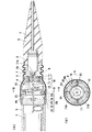
【図1】本発明の第一実施形態装置の断面を示し、(A)はケーブルの軸線を含む面での断面図、(B)は(A)におけるB−B断面図であり、又(A)は(B)におけるA−A線で断面されている。
【図2】図1装置の屈曲時の断面図である。
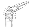
【図3】本発明の第二実施形態装置の断面を示し、(A)はケーブルの軸線を含む面での断面図、(B)は(A)におけるB−B断面図であり、又(A)は(B)におけるA−A線で断面されている。
【図4】図3装置の屈曲時の断面図である。
【符号の説明】
1 ケーブル
2 引留体
3 中継器(海中器機)
4 テールケーブル
4A 可撓部
7 軸体
10 第一継手部
11 中間部材
12 外部材
20 第二継手部
21 固定部材
22 可動部材
24 ピン部材
25 ピン部材
26 可撓カバー
30 第二継手部
31 固定部材
32 可動部材
33 ロッド
33A 軸部
33B 球部
34 ロッド
34A 軸部
34B 球部[0001]
TECHNICAL FIELD OF THE INVENTION
The present invention relates to a universal joint for connecting a submarine cable.
[0002]
[Prior art]
The submarine cable is moored at the end by a tether, and is connected to another submarine cable via a submarine device such as a repeater to obtain a predetermined length. When the cable is laid on the seabed or collected from the seabed, the cable is sent to the seabed while being wound and supported by a sheave or a drum engine provided at the bow or stern of the ship, or is lifted. At the time of winding support by the sheave, the cable can freely bend along the sheave, but the undersea equipment itself and the anchoring body itself cannot bend, so that the bending cable does not receive large bending stress, The undersea equipment and the tonnage body are connected by a universal joint.
[0003]
As such a universal joint, for example, one having a so-called gimbal mechanism as disclosed in Japanese Utility Model Publication No. 5-36088 and Japanese Patent Laid-Open No. 10-260331 is known. In this gimbal mechanism, a shaft body for guiding the tail cable through has a spherical portion, and this spherical portion is accommodated in the inner diameter of the inner ring member, and both are rotatably connected by a pin orthogonal to the shaft body axis, The inner ring member and the outer ring member that accommodates the inner ring member are rotatably connected to each other by the above-mentioned pin and another pin perpendicular to the axis of the shaft body. Thus, it is freely rotatable around two axes orthogonal to the shaft axis.
[0004]
[Problems to be solved by the invention]
However, in the above-described known gimbal mechanism, the members constituting the gimbal mechanism have a limited movable range due to the mechanism, and the rotation angle, that is, the bending angle cannot be made too large.
[0005]
Therefore, a universal joint in which the gimbal mechanism as described above is provided at two locations in the longitudinal direction of the cable is also known. In this way, a large total bending angle can be ensured by both gimbal mechanisms.
[0006]
In the universal joint, in addition to the space for the two gimbal mechanisms, a space for accommodating the flexible portion of the tail cable must be ensured, so that the longitudinal dimension of the universal joint increases. An increase in this size means an increase in weight, which increases the load on the laying machine on the laying ship and makes its operation difficult. Furthermore, the workability in the limited space of the laying ship is deteriorated.
[0007]
In view of such circumstances, an object of the present invention is to provide a universal joint for connecting a submarine cable, which can secure a large bending angle and can be reduced in size and weight in the longitudinal direction.
[0008]
[Means for Solving the Problems]
The universal joint for connecting a submarine cable according to the present invention, the cable anchored by the anchoring body and the undersea equipment connect between the anchoring body and the undersea equipment connecting the undersea equipment via a tail cable, so that both can be freely bent. connect.
[0009]
In such a universal joint, in the present invention, the universal joint has a first joint part on the anchoring body side and a second joint part on the underwater equipment side, and the first joint part is attached to the anchoring body and has a tail cable guide hole. It has a shaft formed on the axis, an intermediate member and an outer member sequentially arranged radially outward with respect to the shaft. The shaft body and the intermediate member are around one axis located in a plane orthogonal to the axis of the shaft body, and the intermediate member and the outer member are around another axis perpendicular to the one axis in the orthogonal plane. Each is rotatably connected. On the other hand, the second joint portion is connected to the fixed member attached to the undersea device and the fixed member so as to be rotatable with respect to the fixed member around one axis positioned in a plane orthogonal to the longitudinal direction of the cable. Movable member. The movable member of the second joint portion and the outer member of the first joint portion are rotatably connected around a rotation axis of the fixed member and an axis perpendicular to the longitudinal direction of the cable. At least the movable member of the fixed member and the movable member forms a hollow space penetrating in the cable longitudinal direction, and at least a part of the flexible portion of the tail cable is housed in the hollow space.
[0010]
According to the present invention having such a configuration, it is possible to sufficiently bend both the first joint portion and the second joint portion around an arbitrary axis on a plane perpendicular to the longitudinal direction of the cable. Is large enough. Moreover, in the second joint portion, at least a part of the flexible portion of the tail cable is accommodated in the hollow space formed in the movable member, so that a space for that need not be provided at another position in the longitudinal direction. The device is reduced in size in the longitudinal direction. This achieves significant weight savings for such devices, which are usually quite heavy. In addition, workability in a limited space on a laid ship when laying or pulling up a cable is improved.
[0011]
In the present invention, in the second joint portion, the fixed member forms an outer ring and the movable member forms an inner ring arranged in the outer ring, the outer ring and the inner ring are pin members, and the outer member of the inner ring and the first joint portion is formed of another member. The pin members can be connected so as to be rotatable around the axis of each pin member. This configuration has a relatively simple structure, but since the hollow space formed in the movable member cannot be so large, it is effective when the flexible portion of the tail cable accommodated therein is small in the radial direction.
[0012]
Further, in the present invention, instead of the above-described mode in which the pin member is made rotatable, the second joint portion is formed by a ring body in which a fixed member and a movable member are arranged side by side in the longitudinal direction of the cable. The fixed member and the movable member, and the movable member and the outer member of the first joint portion are connected by a plurality of rods provided in parallel with the cable axis, respectively, and each rod has a shaft portion and a sphere portion. The shaft is attached to one of the fixed member and the movable member, and the movable member and one of the outer members, and is supported by the other member so as to be rotatable and slidable in the axial direction by the ball. You can also be. According to this embodiment, although the structure is slightly complicated, a large hollow space for the movable member can be secured, so that the flexible portion of the tail cable accommodated therein is formed large in the radial direction. Even if it is wound, it can be sufficiently accommodated.
[0013]
In the present invention, in any case, the first joint portion and the second joint portion are protected from the outside by being covered by the tubular flexible cover attached to the anchor and the undersea device. Is preferred.
[0014]
BEST MODE FOR CARRYING OUT THE INVENTION
Hereinafter, an embodiment of the present invention will be described with reference to the accompanying drawings.
[0015]
<First embodiment>
In FIG. 1, a cable, for example, an optical cable 1 is moored to a tether 2, and is connected to a tail cable 4 from an underwater device, for example, a repeater 3, by the tether 2. The cable 1, the tail cable 4, the anchoring body 2, and the connection method thereof are widely known, and are not the main subject of the present invention, and thus will not be described in detail.
[0016]
The staying body 2 and the cable 1 are held by a rubber mold body 5, and the repeater 3 is housed in a cylindrical housing 6. The tether 2 and the housing 6 are connected by a first joint 10 and a second joint 20, and in each of the joints 10, 20, at a plane perpendicular to the longitudinal direction of the cable. About two orthogonal axes.
[0017]
The anchoring body 2 has a shaft body 7 projecting from the case in the axial direction, and the tip of the shaft body 7 is a ball head 8, and the ball head 8 is formed of two parallel opposed flat surfaces. A portion has been cut away to form surface 8A. A cable guide hole 9 is formed in the shaft body 7, and the tip end of the tail cable 4 is introduced into the tether 2 through the cable guide hole 9.
[0018]
The first joint portion 10 includes a ring-shaped intermediate member 11 that supports the ball head 8 of the shaft 7, a ring-shaped outer member 12 that is externally fitted to the ring-shaped intermediate member 11, the ball head 8, and the intermediate member 11. It has a pin member 13 for rotatably connecting, and a pin member 14 for rotatably connecting the intermediate member 11 and the outer member 12.
[0019]
The intermediate member 11 has, as one inner surface, a cylindrical inner surface portion 11A having the same diameter as the ball head 8 and a sliding contact flat surface 11B which is in sliding contact with a flat surface 8A formed on the ball head 8 and facing the same. The ball head 8 is accommodated in the space formed by the inner surface. The intermediate member 11 and the ball head 8 are rotated about the axis of the pin member 13 by a pair of the pin members 13 located on one diameter line in a plane perpendicular to the longitudinal direction of the cable. They are freely connected. The rotation is performed such that the ball outer surface of the ball head 8 rolls to the cylindrical inner surface portion 11A under the sliding contact guide between the flat surface 8A and the sliding contact flat surface 11B.
[0020]
On the other hand, the intermediate member 11 and the outer member 12 are rotatably connected by another pair of pin members 14 arranged in a direction orthogonal to the pin member 13. As in the case of the ball head 8 and the intermediate member 11, the intermediate member 11 and the outer member 12 have a spherical outer surface and a flat part of the outer surface of the intermediate member 11 so that they can be smoothly rotated. The outer surface of the outer member 12 is provided with a sliding flat surface for slidingly guiding the flat surface and a cylindrical inner surface portion allowing the rolling of the spherical surface. Also, the outer member 12 has a skirt portion 15 extending toward the second joint portion 20 and having a slightly larger diameter while extending from the skirt portion 15 to the pin member 14 in the circumferential direction. The extended arm 16 is provided at a position perpendicular to the position, i.e., at a position corresponding to the pin member 13, extending in the axial direction.
[0021]
The second joint portion 20 has a fixed member 21 screwed to the housing 6 for the relay device 3 and a movable member 22 rotatably connected to the fixed member 21. The fixed member 21 and the movable member 22 form an outer ring and an inner ring.
[0022]
The fixed member 21 has a pair of arms 23 extending in the axial direction at a position of one diameter line from a cylindrical portion screwed to the housing 6, and the arm 23 has a ring-shaped movable member 22. And a pair of pin members 24 so as to be rotatable. The movable member 22 is rotatably connected to the extension arm 16 of the outer member of the first joint portion 10 by another pair of pin members 25 having a positional relationship perpendicular to the pair of pin members 24. I have. The contact surfaces of the movable member 22, the fixed member 21, and the outer member 12 are flat with each other as shown in FIG. 1B, and the rotation around the pin member 24 and the pin member 25 causes the flat surface to rotate. The sliding is performed stably.
[0023]
The movable member 22 is hollow in a ring shape, and accommodates a part of the flexible portion 4A around which the tail cable 4 from the repeater 3 is wound, in the hollow space. Since the tail cable 4 is protected by the metal tube and has high rigidity, flexibility is obtained by forming such a winding portion.
[0024]
Further, in the present embodiment, a bellows-like rubber flexible cover 26 is attached to protect the range of the first and second joints from the outside.
[0025]
In such a device of the present embodiment, when an external force of bending acts on the cable, the cable rotates around each pin member in the first joint portion 10 and the second joint portion 20 and largely bends as a whole cable. It is possible to do. For example, in FIG. 2, it receives a bending external force in a plane parallel to the paper and rotates around the pin member 13 (see FIG. 1A) and the pin member 25 in a direction perpendicular to the paper. Of course, if the direction of the bending external force acts in a plane shifted in the circumferential direction, the first joint 10 turns around both the pin members 13 and 14 and the second joint 20 turns around the two pin members 24 and 25. Move.
[0026]
Thus, in the present embodiment, the cable can be largely bent by the rotation at the joints 10 and 20. Since a part of the flexible portion 4A of the tail cable 4 is accommodated in the internal space of the movable member 22 of the second joint portion 20, the device occupies a space for the flexible portion 4A in the longitudinal direction of the cable. There is no need to separately form the device, so that the size can be significantly reduced in the longitudinal direction, and the device can be reduced.
[0027]
<Second embodiment>
Next, the second embodiment shown in FIG. 3 is significantly different from the first embodiment in FIG. 1 in that the fixed member and the movable member are arranged side by side in the second joint portion 30.
[0028]
A fixed member 31 fixed to the housing 6 of the repeater 3 and a ring-shaped movable member 32 arranged in parallel with the fixed member 31 are rods 33 extending in the axial direction at a plurality of circumferential positions (six in the illustrated example). Are connected by The rod 33 has a ball portion 33B at one end of a shaft portion 33A, and a screw portion 33C at the other end. On the other hand, a through-hole is formed in the fixing member 31 at a corresponding position, and this through-hole has a cylindrical inner surface 31A and a spherical seating surface 31B equal to the diameter of the spherical portion 33B of the rod 33, as shown in FIG. In this case, the ball portion 33B of the rod 33 is in contact with the ball seating surface 31B. The screw portion 33C of the rod 33 is screwed to the movable member 32.
[0029]
In the hollow space formed by the fixed member 31 and the movable member 32, a flexible portion 4A around which the tail cable 4 is wound is accommodated.
[0030]
In the present embodiment, the movable member 32 and the outer member 12 of the first joint portion 10 are connected by a rod 34 having the same form as the rod 33 connecting the movable member 32 and the fixed member 31. The rod 34 also has a shaft portion 34A, a ball portion 34B, and a screw portion 34C. The rod portion 34 is engaged with the movable member 32 at the ball portion 34B, and is screwed to the outer member 12 with a screw portion 34C. Since the rods 34 are arranged at the same position in the circumferential direction as the rods 33, the thickness of the movable member 32 is increased. Therefore, the rods 34 are distributed in the circumferential direction so as to be located between the adjacent rods 33.
[0031]
The first joint portion 10 is different from that of FIG. 1 in that the outer member 12 does not have the skirt portion 15 in FIG. 1 and that the rod 34 is screwed, but other points are the same. Since they are the same, the same reference numerals are given to the common parts, and the description thereof will be omitted.
[0032]
In the present embodiment, when the cable receives an external force of bending, the rods 33 and 34 of the rods 33B and 34B rotate spherically on the spherical bearing surfaces of the fixed member 31 and the movable member 32, and as a result, the movable member 32 rotates relative to the fixed member 31 and the outer member 12 rotates relative to the movable member 32. At that time, the distance between the movable member 32 and the fixed member 31 and the distance between the outer member 12 and the movable member 32 are different depending on the circumferential position, and the difference is as shown in FIG. The spherical portions 33B, 34B of 34 are adjusted by sliding in the axial direction on the inner surface of the cylindrical portion of the through hole of the fixing member 31 and the outer member 12.
[0033]
In the present invention, the flexible portion of the tail cable accommodated in the hollow space of the second joint does not need to be wound. The form of the flexible part changes depending on the rigidity of the tail cable. For example, some flexible parts have low rigidity and are straight without being wound.
[0034]
Also, the shaft of the anchoring body does not need to be a spherical head, but may be a conical head.
[0035]
【The invention's effect】
The present invention provides the universal joint in the first joint portion and the second joint portion as described above, so that the entire bending angle can be extremely large, while the tail portion is formed in the hollow space by using the second joint portion as a ring body. Since the flexible portion of the cable is accommodated, there is no need to separately provide a space for accommodating the flexible portion adjacent to the second joint portion in the longitudinal direction of the cable. Is reduced in size, and the size and weight of the device can be reduced. As a result, handling for cable laying and workability during cable laying or pulling up are improved.
[Brief description of the drawings]
1A and 1B are cross-sectional views of a device according to a first embodiment of the present invention, in which FIG. 1A is a cross-sectional view taken along a plane including an axis of a cable, FIG. (A) is a cross section taken along line AA in (B).
FIG. 2 is a cross-sectional view of the device of FIG. 1 when bent.
FIGS. 3A and 3B are cross-sectional views of a device according to a second embodiment of the present invention, in which FIG. 3A is a cross-sectional view taken along a plane including an axis of a cable, FIG. (A) is a cross section taken along line AA in (B).
4 is a cross-sectional view of the device of FIG. 3 when it is bent.
[Explanation of symbols]
1 Cable 2 Tether 3 Repeater (undersea equipment)
4 Tail cable 4A Flexible part 7 Shaft 10 First joint part 11 Intermediate member 12 Outer member 20 Second joint part 21 Fixed member 22 Movable member 24 Pin member 25 Pin member 26 Flexible cover 30 Second joint part 31 Fixed member 32 Movable member 33 Rod 33A Shaft 33B Ball 34 Rod 34A Shaft 34B Ball