JP2004103409A - Battery, its manufacturing method, battery pack, and battery pack module - Google Patents
Battery, its manufacturing method, battery pack, and battery pack module Download PDFInfo
- Publication number
- JP2004103409A JP2004103409A JP2002264020A JP2002264020A JP2004103409A JP 2004103409 A JP2004103409 A JP 2004103409A JP 2002264020 A JP2002264020 A JP 2002264020A JP 2002264020 A JP2002264020 A JP 2002264020A JP 2004103409 A JP2004103409 A JP 2004103409A
- Authority
- JP
- Japan
- Prior art keywords
- battery
- film
- laminated
- width
- assembled
- Prior art date
- Legal status (The legal status is an assumption and is not a legal conclusion. Google has not performed a legal analysis and makes no representation as to the accuracy of the status listed.)
- Pending
Links
- 238000004519 manufacturing process Methods 0.000 title claims description 16
- 229920005989 resin Polymers 0.000 claims abstract description 27
- 239000011347 resin Substances 0.000 claims abstract description 27
- 239000005001 laminate film Substances 0.000 claims description 27
- 229910052751 metal Inorganic materials 0.000 claims description 19
- 239000002184 metal Substances 0.000 claims description 19
- 238000000034 method Methods 0.000 claims description 12
- 230000006835 compression Effects 0.000 claims description 11
- 238000007906 compression Methods 0.000 claims description 11
- 238000000748 compression moulding Methods 0.000 claims description 9
- 238000007731 hot pressing Methods 0.000 claims description 6
- 238000003466 welding Methods 0.000 claims description 6
- 238000010894 electron beam technology Methods 0.000 claims description 2
- 238000000605 extraction Methods 0.000 claims description 2
- 238000000465 moulding Methods 0.000 claims description 2
- XLYOFNOQVPJJNP-UHFFFAOYSA-N water Substances O XLYOFNOQVPJJNP-UHFFFAOYSA-N 0.000 abstract description 6
- 238000007789 sealing Methods 0.000 description 9
- 239000011888 foil Substances 0.000 description 7
- 230000007774 longterm Effects 0.000 description 7
- HBBGRARXTFLTSG-UHFFFAOYSA-N Lithium ion Chemical compound [Li+] HBBGRARXTFLTSG-UHFFFAOYSA-N 0.000 description 6
- -1 for example Polymers 0.000 description 6
- 229910001416 lithium ion Inorganic materials 0.000 description 6
- 229920000139 polyethylene terephthalate Polymers 0.000 description 6
- 239000005020 polyethylene terephthalate Substances 0.000 description 6
- RYGMFSIKBFXOCR-UHFFFAOYSA-N Copper Chemical compound [Cu] RYGMFSIKBFXOCR-UHFFFAOYSA-N 0.000 description 5
- 239000004698 Polyethylene Substances 0.000 description 5
- 229910052782 aluminium Inorganic materials 0.000 description 5
- XAGFODPZIPBFFR-UHFFFAOYSA-N aluminium Chemical compound [Al] XAGFODPZIPBFFR-UHFFFAOYSA-N 0.000 description 5
- 239000002194 amorphous carbon material Substances 0.000 description 5
- 229910052802 copper Inorganic materials 0.000 description 5
- 239000010949 copper Substances 0.000 description 5
- 230000004927 fusion Effects 0.000 description 5
- PXHVJJICTQNCMI-UHFFFAOYSA-N nickel Substances [Ni] PXHVJJICTQNCMI-UHFFFAOYSA-N 0.000 description 5
- 229920000573 polyethylene Polymers 0.000 description 5
- OKTJSMMVPCPJKN-UHFFFAOYSA-N Carbon Chemical compound [C] OKTJSMMVPCPJKN-UHFFFAOYSA-N 0.000 description 4
- WYURNTSHIVDZCO-UHFFFAOYSA-N Tetrahydrofuran Chemical compound C1CCOC1 WYURNTSHIVDZCO-UHFFFAOYSA-N 0.000 description 4
- 238000010586 diagram Methods 0.000 description 4
- 239000003792 electrolyte Substances 0.000 description 4
- 239000010410 layer Substances 0.000 description 4
- YEJRWHAVMIAJKC-UHFFFAOYSA-N 4-Butyrolactone Chemical compound O=C1CCCO1 YEJRWHAVMIAJKC-UHFFFAOYSA-N 0.000 description 3
- WEVYAHXRMPXWCK-UHFFFAOYSA-N Acetonitrile Chemical compound CC#N WEVYAHXRMPXWCK-UHFFFAOYSA-N 0.000 description 3
- 239000003125 aqueous solvent Substances 0.000 description 3
- 239000003575 carbonaceous material Substances 0.000 description 3
- 229920000554 ionomer Polymers 0.000 description 3
- 238000005304 joining Methods 0.000 description 3
- 239000007773 negative electrode material Substances 0.000 description 3
- 239000011255 nonaqueous electrolyte Substances 0.000 description 3
- 229920000642 polymer Polymers 0.000 description 3
- BQCIDUSAKPWEOX-UHFFFAOYSA-N 1,1-Difluoroethene Chemical compound FC(F)=C BQCIDUSAKPWEOX-UHFFFAOYSA-N 0.000 description 2
- ZZXUZKXVROWEIF-UHFFFAOYSA-N 1,2-butylene carbonate Chemical compound CCC1COC(=O)O1 ZZXUZKXVROWEIF-UHFFFAOYSA-N 0.000 description 2
- OIFBSDVPJOWBCH-UHFFFAOYSA-N Diethyl carbonate Chemical compound CCOC(=O)OCC OIFBSDVPJOWBCH-UHFFFAOYSA-N 0.000 description 2
- XTHFKEDIFFGKHM-UHFFFAOYSA-N Dimethoxyethane Chemical compound COCCOC XTHFKEDIFFGKHM-UHFFFAOYSA-N 0.000 description 2
- LCGLNKUTAGEVQW-UHFFFAOYSA-N Dimethyl ether Chemical compound COC LCGLNKUTAGEVQW-UHFFFAOYSA-N 0.000 description 2
- KMTRUDSVKNLOMY-UHFFFAOYSA-N Ethylene carbonate Chemical compound O=C1OCCO1 KMTRUDSVKNLOMY-UHFFFAOYSA-N 0.000 description 2
- XEEYBQQBJWHFJM-UHFFFAOYSA-N Iron Chemical compound [Fe] XEEYBQQBJWHFJM-UHFFFAOYSA-N 0.000 description 2
- WHXSMMKQMYFTQS-UHFFFAOYSA-N Lithium Chemical compound [Li] WHXSMMKQMYFTQS-UHFFFAOYSA-N 0.000 description 2
- 239000004677 Nylon Substances 0.000 description 2
- 229910021383 artificial graphite Inorganic materials 0.000 description 2
- 239000006229 carbon black Substances 0.000 description 2
- 230000000052 comparative effect Effects 0.000 description 2
- 239000004020 conductor Substances 0.000 description 2
- JBTWLSYIZRCDFO-UHFFFAOYSA-N ethyl methyl carbonate Chemical compound CCOC(=O)OC JBTWLSYIZRCDFO-UHFFFAOYSA-N 0.000 description 2
- 239000005038 ethylene vinyl acetate Substances 0.000 description 2
- HCDGVLDPFQMKDK-UHFFFAOYSA-N hexafluoropropylene Chemical group FC(F)=C(F)C(F)(F)F HCDGVLDPFQMKDK-UHFFFAOYSA-N 0.000 description 2
- 230000008595 infiltration Effects 0.000 description 2
- 238000001764 infiltration Methods 0.000 description 2
- 238000010030 laminating Methods 0.000 description 2
- 229910052744 lithium Inorganic materials 0.000 description 2
- 229910002102 lithium manganese oxide Inorganic materials 0.000 description 2
- VLXXBCXTUVRROQ-UHFFFAOYSA-N lithium;oxido-oxo-(oxomanganiooxy)manganese Chemical compound [Li+].[O-][Mn](=O)O[Mn]=O VLXXBCXTUVRROQ-UHFFFAOYSA-N 0.000 description 2
- URIIGZKXFBNRAU-UHFFFAOYSA-N lithium;oxonickel Chemical compound [Li].[Ni]=O URIIGZKXFBNRAU-UHFFFAOYSA-N 0.000 description 2
- NUJOXMJBOLGQSY-UHFFFAOYSA-N manganese dioxide Chemical compound O=[Mn]=O NUJOXMJBOLGQSY-UHFFFAOYSA-N 0.000 description 2
- 229920001778 nylon Polymers 0.000 description 2
- 230000035515 penetration Effects 0.000 description 2
- 239000007774 positive electrode material Substances 0.000 description 2
- RUOJZAUFBMNUDX-UHFFFAOYSA-N propylene carbonate Chemical compound CC1COC(=O)O1 RUOJZAUFBMNUDX-UHFFFAOYSA-N 0.000 description 2
- YLQBMQCUIZJEEH-UHFFFAOYSA-N tetrahydrofuran Natural products C=1C=COC=1 YLQBMQCUIZJEEH-UHFFFAOYSA-N 0.000 description 2
- UUAMLBIYJDPGFU-UHFFFAOYSA-N 1,3-dimethoxypropane Chemical compound COCCCOC UUAMLBIYJDPGFU-UHFFFAOYSA-N 0.000 description 1
- JWUJQDFVADABEY-UHFFFAOYSA-N 2-methyltetrahydrofuran Chemical compound CC1CCCO1 JWUJQDFVADABEY-UHFFFAOYSA-N 0.000 description 1
- 229920000049 Carbon (fiber) Polymers 0.000 description 1
- 229910015015 LiAsF 6 Inorganic materials 0.000 description 1
- 229910013063 LiBF 4 Inorganic materials 0.000 description 1
- 229910012851 LiCoO 2 Inorganic materials 0.000 description 1
- 229910015643 LiMn 2 O 4 Inorganic materials 0.000 description 1
- 229910013290 LiNiO 2 Inorganic materials 0.000 description 1
- 229910013870 LiPF 6 Inorganic materials 0.000 description 1
- 229920003171 Poly (ethylene oxide) Polymers 0.000 description 1
- 239000004743 Polypropylene Substances 0.000 description 1
- FKQOMXQAEKRXDM-UHFFFAOYSA-N [Li].[As] Chemical compound [Li].[As] FKQOMXQAEKRXDM-UHFFFAOYSA-N 0.000 description 1
- 239000006230 acetylene black Substances 0.000 description 1
- 239000000956 alloy Substances 0.000 description 1
- PPTSBERGOGHCHC-UHFFFAOYSA-N boron lithium Chemical compound [Li].[B] PPTSBERGOGHCHC-UHFFFAOYSA-N 0.000 description 1
- DQXBYHZEEUGOBF-UHFFFAOYSA-N but-3-enoic acid;ethene Chemical compound C=C.OC(=O)CC=C DQXBYHZEEUGOBF-UHFFFAOYSA-N 0.000 description 1
- 229910052799 carbon Inorganic materials 0.000 description 1
- 239000004917 carbon fiber Substances 0.000 description 1
- 238000010000 carbonizing Methods 0.000 description 1
- 239000010406 cathode material Substances 0.000 description 1
- 229920002678 cellulose Polymers 0.000 description 1
- 239000001913 cellulose Substances 0.000 description 1
- 150000001786 chalcogen compounds Chemical class 0.000 description 1
- 239000000571 coke Substances 0.000 description 1
- 229920001577 copolymer Polymers 0.000 description 1
- 239000013078 crystal Substances 0.000 description 1
- IEJIGPNLZYLLBP-UHFFFAOYSA-N dimethyl carbonate Chemical compound COC(=O)OC IEJIGPNLZYLLBP-UHFFFAOYSA-N 0.000 description 1
- 230000000694 effects Effects 0.000 description 1
- 239000008151 electrolyte solution Substances 0.000 description 1
- 238000002474 experimental method Methods 0.000 description 1
- PCHJSUWPFVWCPO-UHFFFAOYSA-N gold Chemical compound [Au] PCHJSUWPFVWCPO-UHFFFAOYSA-N 0.000 description 1
- 229910052737 gold Inorganic materials 0.000 description 1
- 239000010931 gold Substances 0.000 description 1
- 238000010438 heat treatment Methods 0.000 description 1
- 238000002347 injection Methods 0.000 description 1
- 239000007924 injection Substances 0.000 description 1
- 229910052742 iron Inorganic materials 0.000 description 1
- 239000002648 laminated material Substances 0.000 description 1
- 229910000625 lithium cobalt oxide Inorganic materials 0.000 description 1
- MHCFAGZWMAWTNR-UHFFFAOYSA-M lithium perchlorate Chemical compound [Li+].[O-]Cl(=O)(=O)=O MHCFAGZWMAWTNR-UHFFFAOYSA-M 0.000 description 1
- 229910003002 lithium salt Inorganic materials 0.000 description 1
- 159000000002 lithium salts Chemical class 0.000 description 1
- BFZPBUKRYWOWDV-UHFFFAOYSA-N lithium;oxido(oxo)cobalt Chemical compound [Li+].[O-][Co]=O BFZPBUKRYWOWDV-UHFFFAOYSA-N 0.000 description 1
- MCVFFRWZNYZUIJ-UHFFFAOYSA-M lithium;trifluoromethanesulfonate Chemical compound [Li+].[O-]S(=O)(=O)C(F)(F)F MCVFFRWZNYZUIJ-UHFFFAOYSA-M 0.000 description 1
- 239000000463 material Substances 0.000 description 1
- 239000002905 metal composite material Substances 0.000 description 1
- 239000007769 metal material Substances 0.000 description 1
- VNWKTOKETHGBQD-UHFFFAOYSA-N methane Chemical compound C VNWKTOKETHGBQD-UHFFFAOYSA-N 0.000 description 1
- 239000000203 mixture Substances 0.000 description 1
- CWQXQMHSOZUFJS-UHFFFAOYSA-N molybdenum disulfide Chemical compound S=[Mo]=S CWQXQMHSOZUFJS-UHFFFAOYSA-N 0.000 description 1
- 229910052982 molybdenum disulfide Inorganic materials 0.000 description 1
- 229910021382 natural graphite Inorganic materials 0.000 description 1
- 229910052759 nickel Inorganic materials 0.000 description 1
- YTBWYQYUOZHUKJ-UHFFFAOYSA-N oxocobalt;oxonickel Chemical compound [Co]=O.[Ni]=O YTBWYQYUOZHUKJ-UHFFFAOYSA-N 0.000 description 1
- 230000035699 permeability Effects 0.000 description 1
- 239000005011 phenolic resin Substances 0.000 description 1
- 229920001200 poly(ethylene-vinyl acetate) Polymers 0.000 description 1
- 229920002239 polyacrylonitrile Polymers 0.000 description 1
- 229920000098 polyolefin Polymers 0.000 description 1
- 229920001155 polypropylene Polymers 0.000 description 1
- 229920001451 polypropylene glycol Polymers 0.000 description 1
- 239000002243 precursor Substances 0.000 description 1
- 230000002265 prevention Effects 0.000 description 1
- 229910052709 silver Inorganic materials 0.000 description 1
- 239000004332 silver Substances 0.000 description 1
- 239000002904 solvent Substances 0.000 description 1
- 239000010935 stainless steel Substances 0.000 description 1
- 229910001220 stainless steel Inorganic materials 0.000 description 1
- 239000000126 substance Substances 0.000 description 1
- HXJUTPCZVOIRIF-UHFFFAOYSA-N sulfolane Chemical compound O=S1(=O)CCCC1 HXJUTPCZVOIRIF-UHFFFAOYSA-N 0.000 description 1
- 239000002345 surface coating layer Substances 0.000 description 1
- 229920001187 thermosetting polymer Polymers 0.000 description 1
- CFJRPNFOLVDFMJ-UHFFFAOYSA-N titanium disulfide Chemical compound S=[Ti]=S CFJRPNFOLVDFMJ-UHFFFAOYSA-N 0.000 description 1
Images


Classifications
-
- B—PERFORMING OPERATIONS; TRANSPORTING
- B29—WORKING OF PLASTICS; WORKING OF SUBSTANCES IN A PLASTIC STATE IN GENERAL
- B29L—INDEXING SCHEME ASSOCIATED WITH SUBCLASS B29C, RELATING TO PARTICULAR ARTICLES
- B29L2031/00—Other particular articles
- B29L2031/34—Electrical apparatus, e.g. sparking plugs or parts thereof
- B29L2031/3468—Batteries, accumulators or fuel cells
-
- Y—GENERAL TAGGING OF NEW TECHNOLOGICAL DEVELOPMENTS; GENERAL TAGGING OF CROSS-SECTIONAL TECHNOLOGIES SPANNING OVER SEVERAL SECTIONS OF THE IPC; TECHNICAL SUBJECTS COVERED BY FORMER USPC CROSS-REFERENCE ART COLLECTIONS [XRACs] AND DIGESTS
- Y02—TECHNOLOGIES OR APPLICATIONS FOR MITIGATION OR ADAPTATION AGAINST CLIMATE CHANGE
- Y02E—REDUCTION OF GREENHOUSE GAS [GHG] EMISSIONS, RELATED TO ENERGY GENERATION, TRANSMISSION OR DISTRIBUTION
- Y02E60/00—Enabling technologies; Technologies with a potential or indirect contribution to GHG emissions mitigation
- Y02E60/10—Energy storage using batteries
Landscapes
- Secondary Cells (AREA)
- Battery Mounting, Suspending (AREA)
- Connection Of Batteries Or Terminals (AREA)
- Sealing Battery Cases Or Jackets (AREA)
Abstract
Description
【0001】
【発明の属する技術分野】
本発明は、電池およびその製造方法、ならびに組電池、組電池モジュールに関する。
【0002】
【従来の技術】
電池の外装として、樹脂膜と金属膜を積層したラミネートフィルムが用いられている。
【0003】
ところで、このラミネートフィルムを用いた電池は、ラミネートフィルムからの水分透過による電池性能の低下という問題がある。これは、ラミネート材の特性として、ラミネート面では、水分の浸入防止性能が優れているが、ラミネート構造の積層断面が露出する側端部からの水分に対しては、その浸入を許してしまう構造となっている。これは、ラミネート構造自体が、その側端部においては金属で覆われておらず、樹脂膜がむきだしになっているため、この樹脂膜を透過または浸透して水分が浸入してしまうためである。
【0004】
このようなラミネートフィルムを外装として用いた電池として、たとえば特許文献1には、ラミネートフィルムの端部に融着代を設けて封止した構造が開示されている。
【0005】
また、特許文献2には、ラミネートフィルムの端部に、さらに封口補助部材によって覆った構造が開示されている。
【0006】
【特許文献1】
特開2001−357826号公報
【特許文献2】
特開2000−223087号公報
【0007】
【発明が解決しようとする課題】
しかしながら、これら従来の構造では、まず前者の場合、融着代を注液口に設けて、この部分のシール不良を防止するためのものであり、電池全周囲にわたるラミネートフィルム同士の接合部における水の浸入に対しては考慮されていない。
【0008】
また、後者の場合には、封口補助部材を取り付けるためにその製造自体が難しく、また製造コストや部品コストの上昇を招くといった問題がある。
【0009】
そこで、本発明の目的は、ラミネートフィルム外装の電池において、防水性を向上させた電池を提供することであり、また、このための電池の製造方法を提供することである。
【0010】
さらに、本発明の他の目的は、ラミネートフィルム側端部からの水分の侵入を防止した電池を用いた組電池を提供することであり、とくに車載用の組電池モジュールを提供することである。
【0011】
【課題を解決するための手段】
本発明は下記の構成により達成される。
【0012】
(1)少なくとも樹脂膜、金属膜、および樹脂膜をこの順序で積層したラミネートフィルムによって外装した電池であって、前記ラミネートフィルム同士が接合される側端部に熱加圧圧縮成型により圧縮変形された圧縮部を有することを特徴とする電池。
【0013】
(2)少なくとも樹脂膜、金属膜、および樹脂膜をこの順序で積層したラミネートフィルムによって外装した電池の製造方法であって、前記ラミネートフィルム同士が接合され接合部を、凸部を有するヒートプレス型によって熱加圧圧縮成型することにより、前記接合部に圧縮部を成型する工程を有することを特徴とする電池の製造方法。
【0014】
(3)上記の電池を複数個、並列および/または直列に接続したことを特徴とする組電池。
【0015】
(4)上記の組電池を複数個、並列および/または直列に接続したことを特徴とする組電池モジュール。
【0016】
【発明の効果】
本発明によれば、ラミネートフィルム側端部に圧縮部を設けたことで、ラミネートフィルムの樹脂膜が圧縮されて、硬く高密度化するため、この部分からの水の浸入を防止する。このため、ラミネートフィルム外装からの防水性能を向上することができる。したがって、電池の長期的信頼性が向上することができる。
【0017】
また、本発明の組電池は、この電池を使用したものであるから、組電池としての長期的信頼性を向上することができる。
【0018】
また、本発明の組電池モジュールは、この組電池を使用したものであるから、組電池モジュールとしての長期的信頼性を向上することができる。
【0019】
【発明の実施の形態】
以下、図面を参照して本発明の実施の形態を説明する。
【0020】
(第1の実施の形態)
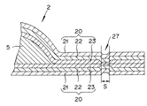
図1は、本発明を適用した電池の概観を示す図面である。図において、(a)は上面図、(b)は(a)における矢印B方向から見た側面図、(c)は(a)における矢印C方向から見た側面図である。また、図2は、この電池のラミネートフィルム側端部の拡大断面図であり、おおむね図1(a)におけるA−A線に沿った部分断面である。
【0021】
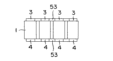
この電池1は、矩形状の外装2内部に電池要素5を収納し、両側に電池のタブ電極3および4を設けたものである。
【0022】
外装2は、樹脂膜21、金属膜22、樹脂膜23をこの順序で積層した3層構造のラミネートフィルム20である。
【0023】
そして、この外装2の側端部は、図2に示すように、ラミネートフィルム20同士が張り合わされた部分(接合部と称する)に、熱加圧圧縮成型することによって形成した圧縮部27を設けている。
【0024】
圧縮部27の圧縮された部分の幅Sは、後述する実施例から、0.5mm以上が好ましく、実施例によれば0.5〜1.0mm程度が好ましい。
【0025】
ラミネートフィルム20は、一般的なラミネートフィルム(ラミネートシートと上されることもある)でよく、たとえば、熱融着性樹脂フィルム、金属膜、剛性を有する樹脂フィルムがこの順序で積層された高分子金属複合フィルムが用いられる。
【0026】
熱融着性樹脂としては、たとえばポリエチレン(PE)、アイオノマー、エチレンビニルアセテート(EVA)等を用いることができる。金属膜としては、たとえばAl箔、Ni箔を用いることができる。剛性を有する樹脂としては、たとえばポリエチレンテレフタレート(PET)、ナイロン等を用いることができる。具体的には、シール面側から外面に向けて積層したPE/Al箔/PETの積層フィルム;PE/Al箔/ナイロンの積層フィルム;アイオノマー/Ni箔/PETの積層フィルム;EVA/Al箔/PETの積層フィルム;アイオノマー/Al箔/PETの積層フィルムなどを用いることができる。熱融着性樹脂フィルムは、電池要素を内部に収納する際のシール層として作用する。金属膜や剛性を有する樹脂膜は、湿性、耐通気性、耐薬品性を外装材に付与する。ラミネートフィルムは、超音波融着等を用いて、容易かつ確実に接合させることができる。
【0027】
次に、このような電池の製造方法について説明する。
【0028】
図3は、上述した電池のラミネートフィルム側端部における圧縮部の成形方法を説明するための図面である。
【0029】
まず、図3(a)に示すように、ラミネートフィルム側端部をヒートプレス装置にセットする。ここで、ヒートプレス装置のヒートプレス型31は、図示するように、ラミネートフィルム側端部における接合部26に位置する部分に凸部32を有する。また、この凸部32は、電池の全周囲にわたり接合部26を圧縮できるように設けられている。
【0030】
続いて、図3(b)に示すように、ヒートプレス型31を過熱しつつラミネートフィルム側端部の接合部26を、電池の全周囲にわたり圧縮して熱加圧圧縮成型を行う。
【0031】
これにより、図3(c)に示すように、ラミネートフィルム側端部の接合部26において、圧縮部27が形成されることにより、この部分における樹脂膜23が圧縮されて硬く、かつ高密度になる。このことにより樹脂膜23の透水性を低くすることができ、この部分からの水の浸入を阻止することができるようになる。
【0032】
しかも、その製造方法は、上述したとおり凸部を有するヒートプレス型により、熱加圧圧縮成型するだけであるので、補助部材なども必要なく、容易に製造することができる。
【0033】
なお、この熱加圧圧縮成型を行う際には、熱加圧圧縮成型の前にラミネートフィルム側端部をあらかじめ加圧による樹脂封止した後であってもよい。
【0034】
(実施例)
ここで、上述した電池の防水試験の結果を説明する。
【0035】
実験は、図1および図2に示した電池について、ラミネートフィルム側端部25の金属膜22の幅Sを変えた電池を試験サンプルとして製作し、この試験サンプルを温度50℃、湿度100%の恒温恒湿槽内に試験サンプルを3ヶ月間放置し、電池内部の水分をカールフィッシャー法にて定量した。
【0036】
試験サンプルは、圧縮部27の幅Sが0.5mm(実施例1)、幅Sが0.7m(実施例2)、幅Sが1.0mm(実施例3)とし、幅Sが0.4mm(比較例1)、幅Sが0.1mm(比較例2)である。
【0037】
試験結果を表1に示す。
【0038】
【表1】
この表1からわかるとおり、圧縮部27の幅Sが0.5mm以上である場合に、水分の浸入をよく防止している。なお、幅Sの上限は、試験を行った試験サンプルの幅Sを1.0mmとしているがもちろんこれ以上であってもよい。ただし、試験結果からは0.5mm程度でも十分である。
【0040】
以上のように、この実施例からも、ラミネートフィルム側端部に圧縮部27を設けることで、水分の浸入を防止することができることがわかる。
【0041】
なお、本第1の実施の形態において、電池外装のラミネートフィルムは、樹脂膜、金属膜、および樹脂膜をこの順序でそれぞれ1層を積層したものであるが、積層させる樹脂膜や金属膜は1層とは限らず、複数層が積層されたものであってもよい。
【0042】
また、熱加圧圧縮成型に用いるヒートプレス型31の凸部32の形状は、図3に示した台形状の他に、たとえば、図4(a)に示すような矩形状、図4(b)に示すよう円弧形状などでもよい。
【0043】
(電池要素)
なお、本第1の実施の形態における電池におけるラミネートフィルムの外装によって覆われた電池要素は、基本的にどのようなものでもよい。
【0044】
一例をあげれば、下記のとおりである。
参考までに、以下、本発明のラミネート電池がリチウムイオン二次電池である場合について簡単に記述する。ただし、本発明のラミネート電池は、リチウムイオン二次電池に限定されるわけではない。なお、電池要素11とは、充放電に実質的に関与する正極、セパレータ、負極などが積層されてなる部分を意味する。
【0045】
[正極]
正極は、アルミニウム等からなる正極集電体の両面に正極材料が結着した構造を有する。正極材料としては、種々の酸化物(LiMn2O4などのリチウムマンガン酸化物;二酸化マンガン;LiNiO2などのリチウムニッケル酸化物;LiCoO2などのリチウムコバルト酸化物;リチウム含有ニッケルコバルト酸化物;リチウムを含む非晶質五酸化バナジウムなど)や、カルコゲン化合物(二硫化チタン、二硫化モリブテンなど)等を挙げることができる。これらの中では、得られるリチウムイオン二次電池の出力特性を考慮すると、リチウムマンガン酸化物またはリチウムニッケル酸化物が好ましい。
【0046】
正極集電体には、導電性を向上させるために、導電性材料を併せて結着させてもよい。導電性材料としては、たとえば、人造黒鉛、カーボンブラック(たとえばアセチレンブラックなど)、ニッケル粉末等が挙げられる。
【0047】
正極集電体としては、たとえばアルミニウム製エキスパンドメタル、アルミニウム製メッシュ、アルミニウム製パンチドメタル等を用いることができる。なお、正極は正極集電体の片面に正極材料を結着させた構造であってもよい。
【0048】
[負極]
負極は、銅などからなる負極集電体の両面に負極材料が結着した構造を有する。負極材料としては、リチウムイオンを吸蔵放出する炭素材料を用いることができる。このような炭素材料としては、天然黒鉛、人造黒鉛、カーボンブラック、活性炭、カーボンファイバー、コークス、有機前駆体(たとえば、フェノール樹脂、ポリアクリロニトリル、セルロース等)を不活性雰囲気中で熱処理して合成した炭素などが挙げられる。好ましくは、負極は非晶質カーボン系材料からなる。本願において「非晶質カーボン系材料」とは結晶構造を有さない炭素材料を意味し、換言すれば非晶質炭素材料を意味する。このような非晶質カーボン系材料は熱硬化性樹脂を炭素化することによって得られる。因みに、放電による電圧依存が大きい非晶質カーボン系材料を用いると、2以上のリチウムイオン二次電池を並列に接続した場合におけるリチウムイオン二次電池のサイクル特性を向上させることができる。
【0049】
負極集電体としては、たとえば銅製エキスパンドメタル、銅製メッシュ、銅製パンチドメタル等を用いることができる。なお、負極は負極集電体の片面に負極材料を結着させた構造であってもよい。
【0050】
[セパレータ]
セパレータは、ポリオレフィン系微多孔質セパレータ、たとえば、ポリエチレン、ポリプロピレンを用いることができ、セパレータ中には、非水電解液が含浸させられる。非水電解液は、非水溶媒に電解質を溶解することにより調製される。非水溶媒としては、エチレンカーボネート(EC)、プロピレンカーボネート(PC)、ブチレンカーボネート(BC)、ジメチルカーボネート(DMC)、ジエチルカーボネート(DEC)、エチルメチルカーボネート(EMC)、γ−ブチロラクトン(γ−BL)、スルホラン、アセトニトリル、1,2−ジメトキシエタン、1,3−ジメトキシプロパン、ジメチルエーテル、テトラヒドロフラン(THF)、2−メチルテトラヒドロフラン等を挙げることができる。非水溶媒は、単独で使用しても、2種以上混合して使用しても良い。電解質としては、たとえば過塩素酸リチウム(LiClO4)、六フッ化リン酸リチウム(LiPF6)、四フッ化ホウ素リチウム(LiBF4)、六フッ化砒素リチウム(LiAsF6)、トリフルオロメタンスルホン酸リチウム(LiCF3SO3)、ビストリフルオロメチルスルホニルイミドリチウム[LiN(CF3SO3)2]等のリチウム塩を挙げることができる。電解質の非水溶媒に対する溶解量は、通常は0.2mol/L〜2mol/L程度である。
【0051】
非水電解液を保持するポリマーとしては、たとえば、ポリエチレンオキサイド誘導体、ポリプロピレンオキサイド誘導体、前記誘導体を含むポリマー、ビニリデンフロライド(VdF)とヘキサフルオロプロピレン(HFP)との共重合体等が挙げられる。
【0052】
[タブ電極]
タブには、銅、鉄から選ばれる金属を用いることができるが、アルミニウム、ステンレス鋼といった金属またはこれらを含む合金材料も同様に使用可能である。また、表面被覆層にはニッケルが最も好適に使用できるが、銀、金といった金属材料も同様に使用可能である。
【0053】
本発明のラミネート電池の製造は、当業者であれば想到するであろう公知技術を用いて行うことができる。たとえば、タブの所定の位置に、熱融着技術を用いてシート部材を配置する。このタブを電池要素と接続する。次に、タブが接続された電池要素をラミネートシートで包み込み、電解液を注入するための封口部を残して熱融着する。このとき、タブはラミネートシート外部に引き出され、所定の位置で熱融着されるようにする。続いて、封口部を通じて電解液を注入し、封口部を熱融着により閉じる。そして、その後、前述したように、ラミネートフィルム側端部の接合部分を電池の全周囲にわたり熱加圧圧縮成型して圧縮部を形成する。
【0054】
なお、ラミネート電池そのものの製造方法は上述したような方法に限定されるものではなく、いかようなものであってもよい。
【0055】
(第2の実施の形態)
第2の実施の形態は、上述した第1の実施の形態による電池を複数個接続した組電池である。
【0056】
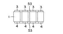
図5は、第2の実施の形態による組電池の斜視図であり、図6は、内部構成を上方から見た図面である。
【0057】
図示するようにこの組電池50は、上述した第1の実施の形態による電池1を複数個直接に接続したものをさらに並列に接続したものである。電池1同士は、導電バー53により各電池のタブ電極3および4が接続されている。この組電池50には電極ターミナル51および52が、この組電池50の電極として組電池50の一側面に設けられている。
【0058】
この組電池50に用いる上述した第1の実施の形態による電池1の形状は、立方体であり、その電池1の幅をa、長さをb、厚さをcとした場合、a/b比が0.3〜1.0の範囲であり、かつa/c比が5〜100の範囲であることが好ましい。具体的には、電池1の幅が50mm〜200mmの範囲、長さが50mm〜300mmの範囲、厚さが2mm〜10mmの範囲であることがより好ましい。
【0059】
電池1をこの大きさとすることで、組電池の製造工程上扱いやすく、また、パッケージングしやすい。さらに、組電池化した際トータルの容積を小さくすることができる
また、電池1から取り出されているそれぞれのタブ電極3および4の幅は、タブ電極取り出し面の幅の20%〜90%であることが好ましい。
【0060】
これにより、必要な電池出力を保ちながら、電極部分のシール性を確保できる。
【0061】
この組電池においては、電池1を直接に接続しさらに並列に接続する際の接続方法として、超音波溶接、熱溶接、レーザー溶接、リベット、かしめ、電子ビームなどを用いることができる。このような接続方法をとることで、長期的信頼性のある組電池を製造することができる。
【0062】
以上のように本第2の実施の形態による組電池によれば、前述した第1の実施の形態による水の浸入を防止することのできる電池を用いて組電池化することで、高容量、高出力と得ることができ、しかも一つひとつの電池の信頼性が高いため、組電池としての長期的信頼性を向上させることができる。
【0063】
なお、組電池としての電池1の接続は、電池1を複数個全て並列に接続してもよいし、また、電池1を複数個全て直列に接続してもよい。
【0064】
(第3の実施の形態)
第3の実施の形態は、上述した第2の実施の形態による組電池を複数個接続した組電池モジュールである。
【0065】
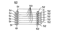
図6は、第2の実施の形態による組電池モジュールの斜視図である。
【0066】
この組電池モジュール60は、前述した第2の実施の形態による組電池50を複数個積層し、各組電池50の電極ターミナル51、52を導電バー61および62によって接続し、モジュール化したものである。
【0067】
このように、組電池50をモジュール化することによって、電池制御を容易にし、たとえば電気自動車やハイブリッド自動車などの車搭用として最適な組電池モジュールとなる。そして、この組電池モジュール60は、上述した組電池を用いたものであるから防水性能が高く、長期の屋外での使用に際しても十分な防水性があり、長期的信頼性の高いものである向上させることができる。
【0068】
(第4の実施の形態)
第4の実施の形態は、上述した第3の実施の形態による組電池モジュールを搭載してなる車両である。この組電池モジュールを用いる自動車としては、たとえば電気自動車、ハイブリッド自動車などである。
【0069】
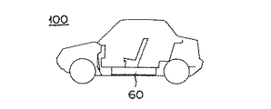
参考までに、図8に、組電池モジュール60を搭載する車両(自動車)100の概略図を示す。車両に搭載される組電池モジュール60は、上記説明した特性を有する。このため、組電池モジュール60を搭載してなる車両は高い耐久性を有し、長期間に渡って使用した後であっても充分な出力を提供しうる。
【図面の簡単な説明】
【図1】本発明を適用した第1の実施の形態における電池の概観構成を示す図面である。
【図2】上記電池のラミネートフィルム側端部の拡大断面図である。
【図3】上記電池の製造方法を説明するための図面である。
【図4】上記電池の製造に用いるヒートプレス型の例を示す図面である。
【図5】本発明を適用した第2の実施の形態における組電池の概観構成を示す図面である。
【図6】第2の実施の形態における組電池を上方から見た内部構成を示す図面である。
【図7】本発明を適用した第3の実施の形態における組電池モジュールの概観構成を示す図面である。
【図8】本発明を適用した第4の実施の形態における車両を示す図面である。
【符号の説明】
1 電池、
20 ラミネートフィルム、
21、23 樹脂膜、
22 金属膜、
26 接合部
27 圧縮部
31 ヒートプレス型、
32 凸部
50 組電池、
60 組電池モジュール
100 車両[0001]
TECHNICAL FIELD OF THE INVENTION
The present invention relates to a battery and a method for manufacturing the same, as well as an assembled battery and an assembled battery module.
[0002]
[Prior art]
BACKGROUND ART A laminate film in which a resin film and a metal film are laminated is used as an exterior of a battery.
[0003]
By the way, the battery using this laminated film has a problem that the battery performance is deteriorated due to moisture permeation from the laminated film. This is because, as a characteristic of the laminate material, the laminate surface has excellent moisture penetration prevention performance, but the structure allows the penetration of moisture from the side edge where the laminated cross section of the laminate structure is exposed. It has become. This is because the laminate structure itself is not covered with metal at its side end, and the resin film is exposed, so that moisture penetrates or penetrates the resin film. .
[0004]
As a battery using such a laminate film as an exterior, for example,
[0005]
Further,
[0006]
[Patent Document 1]
JP 2001-357826 A [Patent Document 2]
Japanese Patent Application Laid-Open No. 2000-223087
[Problems to be solved by the invention]
However, in these conventional structures, first, in the former case, a fusion allowance is provided in the injection port to prevent poor sealing at this portion, and the water at the junction between the laminated films over the entire periphery of the battery is provided. Is not taken into account.
[0008]
In the latter case, there is a problem that the manufacturing itself is difficult because the sealing auxiliary member is attached, and the manufacturing cost and the component cost are increased.
[0009]
Accordingly, an object of the present invention is to provide a battery having a laminated film exterior with improved waterproofness, and an object of the present invention is to provide a battery manufacturing method therefor.
[0010]
Still another object of the present invention is to provide an assembled battery using a battery in which moisture is prevented from entering from an end portion on the side of the laminated film, and in particular, to provide an assembled battery module for a vehicle.
[0011]
[Means for Solving the Problems]
The present invention is achieved by the following configurations.
[0012]
(1) A battery in which at least a resin film, a metal film, and a resin film are packaged with a laminated film in which the laminated films are laminated in this order, and which is compression-deformed at a side end where the laminated films are joined to each other by hot-pressure compression molding. A battery comprising a compressed portion.
[0013]
(2) A method for producing a battery in which at least a resin film, a metal film, and a resin film are packaged with a laminate film in which the laminate films are laminated in this order, wherein the laminate films are joined to each other, and a joint is formed by a heat press type having a convex portion. A method for producing a battery, comprising a step of molding a compression part at the joint part by hot-press compression molding.
[0014]
(3) A battery pack comprising a plurality of the above-mentioned batteries connected in parallel and / or series.
[0015]
(4) An assembled battery module comprising a plurality of the assembled batteries connected in parallel and / or series.
[0016]
【The invention's effect】
According to the present invention, the resin film of the laminate film is compressed and hardened to have a high density by providing the compression portion at the end portion on the side of the laminate film, thereby preventing water from entering from this portion. For this reason, the waterproof performance from the laminate film exterior can be improved. Therefore, the long-term reliability of the battery can be improved.
[0017]
Further, since the battery pack of the present invention uses this battery, the long-term reliability of the battery pack can be improved.
[0018]
Further, since the battery module of the present invention uses the battery module, the long-term reliability of the battery module can be improved.
[0019]
BEST MODE FOR CARRYING OUT THE INVENTION
Hereinafter, embodiments of the present invention will be described with reference to the drawings.
[0020]
(First Embodiment)
FIG. 1 is a drawing showing an overview of a battery to which the present invention is applied. In the drawings, (a) is a top view, (b) is a side view as viewed from the direction of arrow B in (a), and (c) is a side view as viewed from the direction of arrow C in (a). FIG. 2 is an enlarged cross-sectional view of the laminate film side end of the battery, and is generally a partial cross-section along the line AA in FIG.
[0021]
The
[0022]
The
[0023]
As shown in FIG. 2, the side end of the
[0024]
The width S of the compressed portion of the
[0025]
The
[0026]
As the heat-fusible resin, for example, polyethylene (PE), ionomer, ethylene vinyl acetate (EVA) and the like can be used. As the metal film, for example, an Al foil or a Ni foil can be used. As the resin having rigidity, for example, polyethylene terephthalate (PET), nylon or the like can be used. Specifically, a laminated film of PE / Al foil / PET laminated from the sealing surface side to the outer surface; a laminated film of PE / Al foil / Nylon; a laminated film of ionomer / Ni foil / PET; EVA / Al foil / A PET laminated film; an ionomer / Al foil / PET laminated film or the like can be used. The heat-fusible resin film functions as a seal layer when the battery element is housed inside. The metal film or the rigid resin film imparts moisture, air resistance, and chemical resistance to the exterior material. The laminate film can be easily and reliably joined by using ultrasonic fusion or the like.
[0027]
Next, a method for manufacturing such a battery will be described.
[0028]
FIG. 3 is a view for explaining a method of forming a compression section at an end of the battery on the laminate film side.
[0029]
First, as shown in FIG. 3 (a), the side end of the laminate film is set in a heat press. Here, the
[0030]
Subsequently, as shown in FIG. 3B, while the
[0031]
As a result, as shown in FIG. 3 (c), the compressed
[0032]
In addition, since the manufacturing method simply involves hot press compression molding using a heat press mold having a convex portion as described above, it can be easily manufactured without an auxiliary member or the like.
[0033]
In addition, when performing this hot-pressing compression molding, before the hot-pressing compression molding, the laminated film side end may be after resin-sealing by pressurization in advance.
[0034]
(Example)
Here, the results of the above-described battery waterproof test will be described.
[0035]
In the experiment, for the batteries shown in FIGS. 1 and 2, a battery was manufactured as a test sample in which the width S of the
[0036]
In the test sample, the width S of the
[0037]
Table 1 shows the test results.
[0038]
[Table 1]
As can be seen from Table 1, when the width S of the
[0040]
As described above, also from this example, it can be seen that the provision of the
[0041]
In the first embodiment, the laminate film of the battery exterior is formed by laminating a resin film, a metal film, and one resin film in this order, respectively. The number of layers is not limited to one, and a plurality of layers may be stacked.
[0042]
Further, in addition to the trapezoidal shape shown in FIG. 3, the shape of the
[0043]
(Battery element)
The battery element of the battery according to the first embodiment, which is covered with the laminate film, may be basically any type.
[0044]
An example is as follows.
For reference, the case where the laminated battery of the present invention is a lithium ion secondary battery will be briefly described below. However, the laminated battery of the present invention is not limited to a lithium ion secondary battery. In addition, the battery element 11 means a portion formed by laminating a positive electrode, a separator, a negative electrode, and the like that substantially participate in charge and discharge.
[0045]
[Positive electrode]
The positive electrode has a structure in which a positive electrode material is bonded to both surfaces of a positive electrode current collector made of aluminum or the like. Examples of the cathode material include various oxides (lithium manganese oxide such as LiMn 2 O 4 ; manganese dioxide; lithium nickel oxide such as LiNiO 2 ; lithium cobalt oxide such as LiCoO 2 ; lithium-containing nickel cobalt oxide; And chalcogen compounds (such as titanium disulfide and molybdenum disulfide). Among these, lithium manganese oxide or lithium nickel oxide is preferable in consideration of the output characteristics of the obtained lithium ion secondary battery.
[0046]
A conductive material may be bound to the positive electrode current collector in order to improve conductivity. Examples of the conductive material include artificial graphite, carbon black (eg, acetylene black), nickel powder, and the like.
[0047]
As the positive electrode current collector, for example, aluminum expanded metal, aluminum mesh, aluminum punched metal, or the like can be used. Note that the positive electrode may have a structure in which a positive electrode material is bound to one surface of a positive electrode current collector.
[0048]
[Negative electrode]
The negative electrode has a structure in which a negative electrode material is bonded to both surfaces of a negative electrode current collector made of copper or the like. As the negative electrode material, a carbon material that stores and releases lithium ions can be used. As such a carbon material, natural graphite, artificial graphite, carbon black, activated carbon, carbon fiber, coke, and an organic precursor (eg, phenol resin, polyacrylonitrile, cellulose, etc.) were synthesized by heat treatment in an inert atmosphere. Carbon and the like. Preferably, the negative electrode is made of an amorphous carbon-based material. In the present application, "amorphous carbon-based material" means a carbon material having no crystal structure, in other words, an amorphous carbon material. Such an amorphous carbon-based material is obtained by carbonizing a thermosetting resin. Incidentally, when an amorphous carbon-based material having a large voltage dependency due to discharge is used, the cycle characteristics of the lithium ion secondary battery when two or more lithium ion secondary batteries are connected in parallel can be improved.
[0049]
As the negative electrode current collector, for example, a copper expanded metal, a copper mesh, a copper punched metal, or the like can be used. Note that the negative electrode may have a structure in which a negative electrode material is bound to one surface of a negative electrode current collector.
[0050]
[Separator]
As the separator, a polyolefin-based microporous separator, for example, polyethylene or polypropylene can be used, and the separator is impregnated with a non-aqueous electrolyte. The non-aqueous electrolyte is prepared by dissolving the electrolyte in a non-aqueous solvent. Examples of the non-aqueous solvent include ethylene carbonate (EC), propylene carbonate (PC), butylene carbonate (BC), dimethyl carbonate (DMC), diethyl carbonate (DEC), ethyl methyl carbonate (EMC), and γ-butyrolactone (γ-BL). ), Sulfolane, acetonitrile, 1,2-dimethoxyethane, 1,3-dimethoxypropane, dimethyl ether, tetrahydrofuran (THF), 2-methyltetrahydrofuran and the like. The non-aqueous solvents may be used alone or as a mixture of two or more. Examples of the electrolyte include lithium perchlorate (LiClO 4 ), lithium hexafluorophosphate (LiPF 6 ), lithium boron tetrafluoride (LiBF 4 ), lithium arsenic hexafluoride (LiAsF 6 ), and lithium trifluoromethanesulfonate. (LiCF 3 SO 3 ) and lithium salts of lithium bistrifluoromethylsulfonylimide [LiN (CF 3 SO 3 ) 2 ]. The amount of the electrolyte dissolved in the nonaqueous solvent is usually about 0.2 mol / L to 2 mol / L.
[0051]
Examples of the polymer holding the non-aqueous electrolyte include a polyethylene oxide derivative, a polypropylene oxide derivative, a polymer containing the derivative, a copolymer of vinylidene fluoride (VdF) and hexafluoropropylene (HFP), and the like.
[0052]
[Tab electrode]
A metal selected from copper and iron can be used for the tab, but a metal such as aluminum or stainless steel or an alloy material containing these can also be used. Nickel is most preferably used for the surface coating layer, but metal materials such as silver and gold can also be used.
[0053]
The production of the laminated battery of the present invention can be carried out by using a known technique that a person skilled in the art would conceive. For example, the sheet member is arranged at a predetermined position of the tab by using a heat fusion technique. This tab is connected to the battery element. Next, the battery element to which the tab is connected is wrapped with a laminate sheet, and heat-sealed while leaving a sealing portion for injecting the electrolyte. At this time, the tab is drawn out of the laminate sheet and is thermally fused at a predetermined position. Subsequently, an electrolytic solution is injected through the sealing portion, and the sealing portion is closed by heat fusion. Then, as described above, the joint at the side end of the laminate film is hot-pressed and compression-molded over the entire periphery of the battery to form a compressed portion.
[0054]
The method for manufacturing the laminated battery itself is not limited to the method described above, and may be any method.
[0055]
(Second embodiment)
The second embodiment is an assembled battery in which a plurality of batteries according to the first embodiment are connected.
[0056]
FIG. 5 is a perspective view of the battery pack according to the second embodiment, and FIG. 6 is a drawing of the internal configuration viewed from above.
[0057]
As shown in the figure, the
[0058]
The shape of the
[0059]
By setting the
[0060]
As a result, the sealing performance of the electrode portion can be secured while maintaining the required battery output.
[0061]
In this assembled battery, ultrasonic welding, heat welding, laser welding, rivets, caulking, electron beam, or the like can be used as a connection method when the
[0062]
As described above, according to the battery pack according to the second embodiment, by using the battery capable of preventing water from entering according to the above-described first embodiment, the battery pack is made into a battery pack, thereby achieving high capacity, Since a high output can be obtained and the reliability of each battery is high, the long-term reliability of the assembled battery can be improved.
[0063]
The connection of the
[0064]
(Third embodiment)
The third embodiment is an assembled battery module in which a plurality of assembled batteries according to the above-described second embodiment are connected.
[0065]
FIG. 6 is a perspective view of the battery module according to the second embodiment.
[0066]
This assembled
[0067]
By modularizing the assembled
[0068]
(Fourth embodiment)
The fourth embodiment is a vehicle equipped with the battery module according to the third embodiment. Vehicles using this battery module include, for example, electric vehicles and hybrid vehicles.
[0069]
For reference, FIG. 8 shows a schematic diagram of a vehicle (automobile) 100 on which the
[Brief description of the drawings]
FIG. 1 is a diagram showing a schematic configuration of a battery according to a first embodiment to which the present invention is applied.
FIG. 2 is an enlarged sectional view of a laminate film side end of the battery.
FIG. 3 is a view for explaining a method of manufacturing the battery.
FIG. 4 is a drawing showing an example of a heat press mold used for manufacturing the battery.
FIG. 5 is a diagram showing an outline configuration of a battery pack according to a second embodiment to which the present invention is applied.
FIG. 6 is a diagram showing an internal configuration of a battery pack according to a second embodiment as viewed from above.
FIG. 7 is a drawing showing an outline configuration of an assembled battery module according to a third embodiment to which the present invention is applied.
FIG. 8 is a view showing a vehicle according to a fourth embodiment to which the present invention is applied.
[Explanation of symbols]
1 battery,
20 laminated film,
21, 23 resin film,
22 metal film,
26
32
60
Claims (11)
前記ラミネートフィルム同士が接合される側端部に熱加圧圧縮成型により圧縮変形された圧縮部を有することを特徴とする電池。At least a resin film, a metal film, and a battery covered with a laminated film in which the resin film is laminated in this order,
A battery comprising: a compression portion that is compressed and deformed by hot-pressing compression molding at a side end where the laminated films are joined to each other.
前記ラミネートフィルム同士が接合され接合部を、凸部を有するヒートプレス型によって熱加圧圧縮成型することにより、前記接合部に圧縮部を成型する工程を有することを特徴とする電池の製造方法。At least a resin film, a metal film, and a method for manufacturing a battery packaged with a laminate film in which a resin film is laminated in this order,
A method for producing a battery, comprising a step of forming a compression part in the bonding part by hot-pressing and molding a bonding part in which the laminate films are bonded to each other using a heat press mold having a convex part.
Priority Applications (1)
| Application Number | Priority Date | Filing Date | Title |
|---|---|---|---|
| JP2002264020A JP2004103409A (en) | 2002-09-10 | 2002-09-10 | Battery, its manufacturing method, battery pack, and battery pack module |
Applications Claiming Priority (1)
| Application Number | Priority Date | Filing Date | Title |
|---|---|---|---|
| JP2002264020A JP2004103409A (en) | 2002-09-10 | 2002-09-10 | Battery, its manufacturing method, battery pack, and battery pack module |
Publications (1)
| Publication Number | Publication Date |
|---|---|
| JP2004103409A true JP2004103409A (en) | 2004-04-02 |
Family
ID=32263569
Family Applications (1)
| Application Number | Title | Priority Date | Filing Date |
|---|---|---|---|
| JP2002264020A Pending JP2004103409A (en) | 2002-09-10 | 2002-09-10 | Battery, its manufacturing method, battery pack, and battery pack module |
Country Status (1)
| Country | Link |
|---|---|
| JP (1) | JP2004103409A (en) |
Cited By (7)
| Publication number | Priority date | Publication date | Assignee | Title |
|---|---|---|---|---|
| JP2008198484A (en) * | 2007-02-13 | 2008-08-28 | Toshiba Corp | Battery and its manufacturing method |
| JP2013157286A (en) * | 2012-01-31 | 2013-08-15 | Toppan Printing Co Ltd | Power storage device |
| WO2013191125A1 (en) * | 2012-06-18 | 2013-12-27 | Necエナジーデバイス株式会社 | Film pack battery |
| WO2015065124A1 (en) * | 2013-11-01 | 2015-05-07 | 주식회사 엘지화학 | Pouch-type secondary battery capable of preventing water permeation |
| EP2884556A4 (en) * | 2012-12-28 | 2016-05-18 | Lg Chemical Ltd | Device and method for sealing pouch case of secondary battery |
| KR102065128B1 (en) * | 2016-03-29 | 2020-01-10 | 주식회사 엘지화학 | Pouch type secondary battery |
| JP2021174629A (en) * | 2020-04-22 | 2021-11-01 | Tdk株式会社 | Nonaqueous electrolyte secondary battery and production method thereof |
-
2002
- 2002-09-10 JP JP2002264020A patent/JP2004103409A/en active Pending
Cited By (12)
| Publication number | Priority date | Publication date | Assignee | Title |
|---|---|---|---|---|
| JP2008198484A (en) * | 2007-02-13 | 2008-08-28 | Toshiba Corp | Battery and its manufacturing method |
| JP2013157286A (en) * | 2012-01-31 | 2013-08-15 | Toppan Printing Co Ltd | Power storage device |
| WO2013191125A1 (en) * | 2012-06-18 | 2013-12-27 | Necエナジーデバイス株式会社 | Film pack battery |
| CN104412407A (en) * | 2012-06-18 | 2015-03-11 | Nec能源元器件株式会社 | Film pack battery |
| JPWO2013191125A1 (en) * | 2012-06-18 | 2016-05-26 | Necエナジーデバイス株式会社 | Film outer battery |
| US9871231B2 (en) | 2012-06-18 | 2018-01-16 | Nec Energy Devices, Ltd. | Film-covered battery |
| US10510997B2 (en) | 2012-06-18 | 2019-12-17 | Envision Aesc Energy Devices Ltd. | Film-covered battery |
| EP2884556A4 (en) * | 2012-12-28 | 2016-05-18 | Lg Chemical Ltd | Device and method for sealing pouch case of secondary battery |
| US9755195B2 (en) | 2012-12-28 | 2017-09-05 | Lg Chem, Ltd. | Apparatus and method for sealing pouch case of secondary battery |
| WO2015065124A1 (en) * | 2013-11-01 | 2015-05-07 | 주식회사 엘지화학 | Pouch-type secondary battery capable of preventing water permeation |
| KR102065128B1 (en) * | 2016-03-29 | 2020-01-10 | 주식회사 엘지화학 | Pouch type secondary battery |
| JP2021174629A (en) * | 2020-04-22 | 2021-11-01 | Tdk株式会社 | Nonaqueous electrolyte secondary battery and production method thereof |
Similar Documents
| Publication | Publication Date | Title |
|---|---|---|
| JP4766057B2 (en) | Nonaqueous electrolyte battery and method for producing nonaqueous electrolyte battery | |
| JP4644899B2 (en) | Electrode and battery, and manufacturing method thereof | |
| JP3758629B2 (en) | Laminate sheet and laminate battery using the same | |
| JP4720384B2 (en) | Bipolar battery | |
| JP4096664B2 (en) | Laminated battery | |
| JP2004087239A (en) | Battery and manufacturing method of the same, battery pack, and battery pack module | |
| JP2013206699A (en) | Electrochemical device | |
| JP2006202680A (en) | Polymer battery | |
| JP2005310588A (en) | Bipolar battery, manufacturing method of bipolar battery, battery pack, and vehicle equipped with them | |
| JP4135474B2 (en) | Laminated secondary battery, assembled battery module comprising a plurality of laminated secondary batteries, assembled battery comprising a plurality of assembled battery modules, and an electric vehicle equipped with any of these batteries | |
| JP4670275B2 (en) | Bipolar battery and battery pack | |
| JP4178926B2 (en) | Bipolar battery, bipolar battery manufacturing method, battery pack and vehicle | |
| JP2004178914A (en) | Bipolar electrode and bipolar secondary battery using the electrode | |
| JP2004095217A (en) | Laminated material for battery case, battery, its manufacturing method, battery pack, and battery pack module | |
| JP4103471B2 (en) | Laminated battery and vehicle equipped with the same | |
| JP3787437B2 (en) | Flat battery and method of manufacturing the same | |
| JP4075534B2 (en) | Laminated secondary battery, assembled battery module, assembled battery and electric vehicle equipped with this battery | |
| JP2004171954A (en) | Laminated secondary battery, battery pack module comprising multiple laminated secondary batteries, battery pack comprising multiple set battery modules, and electric automobile with either battery mounted | |
| JP3597027B2 (en) | Thin battery | |
| JP2001273930A (en) | Manufacturing method of polymer battery | |
| JP2004103409A (en) | Battery, its manufacturing method, battery pack, and battery pack module | |
| JP2001185096A (en) | Cell and method of manufacturing the same | |
| JP3608047B2 (en) | Bipolar type secondary battery manufacturing method and bipolar type secondary battery | |
| JP2000294286A (en) | Polymer lithium secondary battery | |
| JP2001176549A (en) | Non-aqueous electrolytic battery |
Legal Events
| Date | Code | Title | Description |
|---|---|---|---|
| A621 | Written request for application examination |
Free format text: JAPANESE INTERMEDIATE CODE: A621 Effective date: 20031222 |
|
| A977 | Report on retrieval |
Free format text: JAPANESE INTERMEDIATE CODE: A971007 Effective date: 20050414 |
|
| A131 | Notification of reasons for refusal |
Free format text: JAPANESE INTERMEDIATE CODE: A131 Effective date: 20050419 |
|
| A02 | Decision of refusal |
Free format text: JAPANESE INTERMEDIATE CODE: A02 Effective date: 20050816 |