【0001】
【発明の属する技術分野】
本発明は、化学、薬品、食品工業等で、反応槽、撹拌槽として使用される容器(以下、槽容器という)の温度調整装置に関する。
【0002】
【従来の技術】
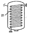
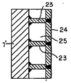
従来、槽容器の除熱または加熱機構としては、図1に示すように容器本体1′の外部にジャケット20を付設したジャケット方式、図2に示すように容器本体1′の内面より内側に螺旋状のパイプ21を固定配置した内部パイプ方式、又は図3に示すように容器本体1′の内面より内側に容器本体の長手方向に延在し、かつ端部がエルボ接続されたパイプ22を容器本体の周方向に蛇行するように固定して配置した内部パイプ方式、更には、図4に示すように容器本体1′の内面と直角に仕切板23を間隔をおいて並設し、仕切板23の先端間に内ストリップ24を跨設し、内ストリップ24と前記容器本体1′の内面との間に仕切板23により仕切られた螺旋状の流路25を形成したインナ−ジャケット方式(特開昭57−147502号公報参照)等が知られている。
【0003】
上記した機構に、例えば除熱を行う場合には、冷媒として例えばブライン、水等を要求される温度に冷凍機を用いて冷却し、ポンプ等を用いて圧送し、例えばジャケット20の下部から入れ、上部から排出し返送する方法で行われていた。
【0004】
【発明が解決しようとする課題】
しかしこの方法は、複数の槽容器を同時に異なる温度に調整する場合には、各槽容器ごとに温度調整装置を設置する必要があり、設備費がかかる上に、維持管理が面倒であるという問題がある。また、冷凍機等の温度調整機構の温度設定が、槽容器で必要とされる温度範囲の設定とは一致しない場合があり、その場合に、温度管理が困難になるという問題があった。
本発明は、特に複数の槽容器の温度管理を設備費、維持費をかけずに一括して行うことができ、槽容器の微妙な温度管理にも対応できる槽容器の温度調整装置を提供することを目的とする。
【0005】
【課題を解決するための手段】
本発明者等は、上記課題を解決すべく鋭意検討した結果、温度調整を行うための媒体(以下、温調媒体という)は、一箇所で一定の温度に管理して各槽容器に送流し、槽容器ごとに温調媒体を循環させる流路を設け、その流路を循環させることにより各槽容器の設定温度範囲とし、各槽容器設定温度範囲を外れたときには、集中管理されている温調媒体を供給し温度調整を行うことで、上記課題を解決することをできることを見出し、本発明を完成するに至った。
【0006】
即ち、本発明は
(1)槽容器に備えられた加熱又は冷却用の温調媒体を有する温調エレメント、温調媒体を所定の温度にする温度調整機構、温度調節機構と温調エレメントを結ぶ温調媒体流路を含む槽容器温度調整装置において、さらに温調媒体を循環させる流路を設けたことを特徴とする槽容器温度調整装置に関し、
(2)温調媒体を循環させる流路に、温調媒体を循環させる装置を設けたことを特徴とする(1)に記載の槽容器温度調整装置、
(3)温調媒体を循環させる流路に、温度センサーを設け、温度調節機構と温調エレメントを結ぶ温調媒体流路の温調エレメント流入側に設けられた弁の開閉と該温度センサーを連動させたことを特徴とする(1)または(2)に記載の槽容器温度調整装置、
(4)温調媒体を循環させる流路を、温度調節機構と温調エレメントを結ぶ温調媒体流路のバイパスとして設けたことを特徴とする(1)〜(3)のいずれかに記載の槽容器温度調整装置、
(5)複数の槽容器を同時に異なった温度に調整することを特徴とする(1)〜(4)のいずれかに記載の槽容器温度調整装置に関する。
さらに、
(6)槽容器に備えられた加熱又は冷却用の温調媒体を有する温調エレメント、温調媒体を所定の温度にする温度調整機構、温度調節機構と温調エレメントを結ぶ温調媒体流路、さらに温調媒体を循環させる流路を含む槽容器温度調整装置を用い、温度調節機構により所定の温度に調整された温調媒体を、温調媒体を循環させる流路で循環させることにより、槽容器を所定温度範囲に調整し、槽容器の所定温度範囲から外れた時に、温度調節機構により所定の温度に調整された温調媒体を供給し、槽容器を所定温度範囲に調整することを特徴とする槽容器温度調整方法に関する。
【0007】
【発明の実施の形態】
本発明の装置が備え付けられる槽容器は、化学プラント、食品プラント、薬品プラント等の温度調整が必要な工程に用いられる容器であれば、特にその形状、材質、様式、用途等には制限されない。具体的には、化学ブラントとに用いられる反応槽、分液槽、後処理、蒸留槽、食品プラントで用いられる醗酵槽、また、製品貯槽等を例示することができる。
【0008】
本発明を構成する温調媒体は、温度調整に用いられる媒体を示し、冷却に用いられるブライン、水等の冷媒、加熱に用いられるシリコンオイル、パラフィン系鉱油、アルキルベンゼン、スチーム等の熱媒を例示することができる。
【0009】
本発明を構成する温調エレメントは、先に図示した公知のものはいずれも採用することができる。また、特開平8−126837号公報、特開平8−126838号公報、特開平7−185314号等の公報に記載された従来の改良型を用いることもできる。
【0010】
本発明を構成する温調媒体を所定の温度にする温度調整機構は、温調媒体を所定温度に調整できるものであれば特に制限されない。例えば、加熱する場合であれば、媒体ボイラーによりスチームのように蒸気を発生させ凝縮伝熱させる気相加熱方式、加熱炉により加熱する熱油のポンプにより循環せしめて顕熱により加熱、冷却する液相方式等を例示することができ、冷却する場合であれば、低温冷媒タンク内に低温液化ガスの流路をコイル状に設けたタンク&コイル式、低温液化ガスにより所定の温度に冷却されている室内に低温冷媒流路を設けた恒温槽方式等を例示することができる。これらの温度調整機構は、各槽容器ごとに設けることもできるが、本発明の装置においては、一箇所で集中管理することで、プラント全体または一部の槽容器の温度管理が可能となる。
【0011】
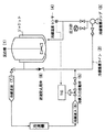
本発明の装置の好ましい一実施形態を図5に示す。図5には、冷却装置の概念図を示しており、冷媒で冷却しながら行うに必要なジャケットと撹伴機付き反応槽(1)、反応槽ジャケットとポンプを介して冷媒を循環させる冷媒循環ライン(2)と冷媒逆流用弁(8)、冷媒の流入を自動弁で調整しジャケットと冷媒ラインの冷媒を循環させる冷媒循環ポンプ(3)、この循環ラインの温度を監視する冷媒温度センサー(4)とセンサーに連動する冷媒入りロ自動弁(5)、冷媒流入ライン(6)および冷媒返送ライン(7)を示す。
【0012】
冷媒循環ライン(2)は、冷媒流入ライン(6)および冷媒返送ライン(7)とは繋がらない別の位置に設けることも可能であるが、図5に示すように、冷凍機に繋がる冷媒流入ライン(6)および冷媒返送ライン(7)の一部にバイパスとして設けるのが好ましい。このように設置することで、複雑な配管を増やすことなくしかも、温度管理を容易に行うことができる。
また、冷媒循環ライン(2)を循環する冷媒が、冷媒返送ライン(7)に流入するのを防止するため、冷媒返送ライン(7)の位置を冷媒循環ライン(2)のジャケット出ロ側の位置よりも、若干高くしておくのが好ましい。
【0013】
冷媒循環ポンプ(3)の種類は特に制限はないが、具体的にはノンシールタイプのボンプを好ましく例示することができる。循環ポンプの吐出圧力は温度調節を行う槽容器の大きさと位置、配管径、ポンプの大きさ、設置場所などによって異なり、さらに、調整する温度範囲の制御の程度によっても異なる。
また、冷媒循環ライン(2)で循環する冷媒温度が設定温度より高くなり、自動弁開度が大きくなり冷やされた冷媒がより多く流入したとき、ジャケット出ロに接続されている冷媒返送ライン(7)ヘ直接流れないように冷媒返送ライン(7)と冷媒循環ライン(2)の間に逆流防止弁(8)を設けるのが好ましい。
【0014】
冷媒循環ライン中の冷媒温度は、冷媒温度センサー(4)を設けて監視するのが好ましく、さらに、冷媒温度センサーと自動弁(5)を連動しておき、冷媒循環ライン中の温度が設定温度範囲外になった場合には、自動弁(5)が開き冷媒を冷媒循環ライン(2)に流入させることで温度調節を行うのが好ましい。
【0015】
また、同じ反応槽でエ程ごとに冷却温度を変えて反応する場合においても、冷凍機の設定温度を変更することなく、冷媒循環ラインで温度調整を行うことが可能である。また、複数の槽容器を、同時に異なった温度に調整する場合においても、冷凍機等の温度調整機構を槽容器ごとに設けることなく、一箇所で、槽容器よりも少ない設備で対応することが可能となる。
【0016】
以下、実施例を用いて本発明を更に詳細に説明するが、本発明は実施例に限定されるものではない。
【0017】
【実施例】
実施例1
6m3GL反応槽にトルエンとp−ニトロベンジルアルコールを仕込み撹伴下にホスゲンガスを吹き込んで、p−ニトロベンジルクロロホーメイトを合成した。反応装置、冷却装置は図5に示す装置を用いた。反応槽温度を−3〜−1℃に保持するため、冷凍機から流入する−8〜−10℃のブライン(50体積/体積%のエチレングリコール水溶液)を冷媒循環ライン(2)に流入させ冷媒循環ポンプ(3)で循環させた。反応槽の温度が22℃から次第に下がり、冷媒温度センサー(4)の設定温度を−3〜−1℃とした。冷媒入りロ自動弁(5)の開度は5%で冷却されたブラインがほとんど入ってこない状態で冷媒循環ライン(2)のみで冷却していた。その後、反応槽内は設定された温度範囲で安定した。次にホスゲンガスを導入し反応を開始した。反応熱で反応槽内温が0〜2°Cに上昇したため、冷媒流入自動弁(5)の開度が30%になり、−3〜−1℃に保持するようにコントロールした。反応を通じて、温度管理が容易であり、反応熱を抑えることができ、反応が暴走することはなかった。
【0018】
【発明の効果】
以上述べたように、本発明の装置を用いることにより、複数の槽容器の異なる温度での温度管理を、一箇所の設備で行うことが可能となり、一つの槽容器においても異なった温度管理に迅速に対応ができ、さらに、急激な温度変化への対応を円滑に行うことができる。製造において温度管理は重要であり、本発明の産業上の利用価値は高いと言える。
【図面の簡単な説明】
【図1】槽容器の温度管理を行う従来の装置の縦断面図を示す。
【図2】槽容器の温度管理を行う従来の装置の縦断面図を示す。
【図3】槽容器の温度管理を行う従来の装置の縦断面図を示す。
【図4】槽容器の温度管理を行う従来の装置の縦断面図を示す。
【図5】本発明の温度調整装置の一実施形態を示す。[0001]
TECHNICAL FIELD OF THE INVENTION
The present invention relates to a temperature control device for a container (hereinafter, referred to as a tank container) used as a reaction tank or a stirring tank in the chemical, pharmaceutical, food, and the like.
[0002]
[Prior art]
Conventionally, as a heat removing or heating mechanism for a tank container, a jacket 20 is provided outside a container main body 1 'as shown in FIG. 1, and a spiral is formed inside the inner surface of the container main body 1' as shown in FIG. An inner pipe system in which a pipe 21 is fixedly arranged, or as shown in FIG. 3, a pipe 22 which extends inward from the inner surface of the container body 1 'in the longitudinal direction of the container body and has an elbow-connected end. An internal pipe system fixed and arranged so as to meander in the circumferential direction of the main body, and furthermore, as shown in FIG. 4, a partition plate 23 is juxtaposed at a right angle to the inner surface of the container main body 1 'at intervals. An inner jacket 24 in which an inner strip 24 is straddled between the tips of the inner strip 23 and a spiral flow path 25 partitioned by a partition plate 23 between the inner strip 24 and the inner surface of the container body 1 '. No.57-147502 Broadcast reference), and the like are known.
[0003]
In the above mechanism, for example, when performing heat removal, for example, brine, water, or the like as a refrigerant is cooled to a required temperature using a refrigerator, and is pumped using a pump or the like, and is put in from the lower portion of the jacket 20, for example. Was done by a method of discharging from the top and returning.
[0004]
[Problems to be solved by the invention]
However, this method requires the installation of a temperature control device for each of the tanks when simultaneously adjusting the temperature of a plurality of tanks to different temperatures, which leads to an increase in equipment costs and troublesome maintenance. There is. Further, there is a case where the temperature setting of the temperature adjusting mechanism such as the refrigerator does not match the setting of the temperature range required for the vessel, and in that case, there is a problem that the temperature management becomes difficult.
The present invention provides a temperature control device for a tank container that can perform temperature control of a plurality of tank containers in a lump without incurring equipment costs and maintenance costs, and can cope with delicate temperature control of the tank container. The purpose is to:
[0005]
[Means for Solving the Problems]
The present inventors have conducted intensive studies to solve the above problems, and as a result, a medium for performing temperature control (hereinafter, referred to as a temperature control medium) is controlled to a constant temperature at one location and sent to each tank container. A flow path for circulating a temperature control medium is provided for each vessel, and the temperature is controlled centrally when the temperature is out of the set temperature range for each vessel by circulating the flow path. It has been found that the above problems can be solved by supplying a conditioning medium and adjusting the temperature, and the present invention has been completed.
[0006]
That is, the present invention provides (1) a temperature control element having a temperature control medium for heating or cooling provided in a tank container, a temperature control mechanism for setting the temperature control medium to a predetermined temperature, and connecting the temperature control mechanism and the temperature control element. In a vessel temperature control device including a temperature control medium flow path, a bath vessel temperature control apparatus characterized by further comprising a flow path for circulating a temperature control medium,
(2) The tank container temperature control device according to (1), wherein a device for circulating the temperature control medium is provided in a flow path for circulating the temperature control medium.
(3) A temperature sensor is provided in the flow path for circulating the temperature control medium, and a valve provided on the temperature control element inflow side of the temperature control medium flow path connecting the temperature control mechanism and the temperature control element is opened and closed, and the temperature sensor is used. (1) or (2), wherein the temperature of the vessel is adjusted,
(4) The method according to any one of (1) to (3), wherein the flow path for circulating the temperature control medium is provided as a bypass of the temperature control medium flow path connecting the temperature control mechanism and the temperature control element. Tank vessel temperature controller,
(5) The tank container temperature adjusting device according to any one of (1) to (4), wherein the plurality of tank containers are simultaneously adjusted to different temperatures.
further,
(6) A temperature control element having a temperature control medium for heating or cooling provided in the tank container, a temperature control mechanism for setting the temperature control medium to a predetermined temperature, a temperature control medium flow path connecting the temperature control mechanism and the temperature control element. Further, by using a vessel temperature control device including a flow path for circulating the temperature control medium, by circulating the temperature control medium adjusted to a predetermined temperature by the temperature control mechanism in the flow path for circulating the temperature control medium, The temperature of the bath container is adjusted to a predetermined temperature range, and when the temperature of the bath container deviates from the predetermined temperature range, a temperature control medium adjusted to a predetermined temperature by a temperature control mechanism is supplied to adjust the bath container to a predetermined temperature range. The present invention relates to a method for adjusting a temperature of a tank container.
[0007]
BEST MODE FOR CARRYING OUT THE INVENTION
The tank container provided with the apparatus of the present invention is not particularly limited in its shape, material, style, use, and the like, as long as it is a container used in a process requiring temperature adjustment, such as a chemical plant, a food plant, and a pharmaceutical plant. Specific examples include a reaction tank, a liquid separation tank, a post-treatment, a distillation tank, a fermentation tank used in a food plant, and a product storage tank used for a chemical plant.
[0008]
The temperature control medium constituting the present invention refers to a medium used for temperature control, and includes a cooling medium such as brine and water used for cooling, and a heat medium such as silicon oil, paraffinic mineral oil, alkylbenzene, and steam used for heating. can do.
[0009]
As the temperature control element constituting the present invention, any of the well-known elements shown above can be adopted. Further, conventional improved types described in Japanese Patent Application Laid-Open Nos. 8-126268, 8-12638, and 7-185314 can also be used.
[0010]
There is no particular limitation on the temperature adjusting mechanism for adjusting the temperature adjusting medium to a predetermined temperature, as long as the temperature adjusting medium can adjust the temperature adjusting medium to a predetermined temperature. For example, in the case of heating, a vapor phase heating method in which steam is generated and condensed and transferred as steam by a medium boiler, a liquid circulated by a hot oil pump heated by a heating furnace, and heated and cooled by sensible heat A phase and the like can be exemplified. In the case of cooling, a tank & coil type in which a flow path of a low-temperature liquefied gas is provided in a coil shape in a low-temperature refrigerant tank is cooled to a predetermined temperature by the low-temperature liquefied gas. A constant-temperature bath system in which a low-temperature refrigerant flow path is provided in a room where the air conditioner is located can be exemplified. These temperature adjustment mechanisms can be provided for each tank vessel. However, in the apparatus of the present invention, the temperature of the entire vessel or a part of the vessel can be controlled by centrally controlling the temperature at one place.
[0011]
One preferred embodiment of the device of the present invention is shown in FIG. FIG. 5 shows a conceptual diagram of a cooling device, in which a jacket and a reaction tank (1) with a stirrer necessary for cooling while cooling with a refrigerant, and a refrigerant circulation for circulating the refrigerant through a reaction tank jacket and a pump. A line (2) and a refrigerant backflow valve (8), a refrigerant circulating pump (3) for adjusting the inflow of the refrigerant by an automatic valve and circulating the refrigerant in the jacket and the refrigerant line, and a refrigerant temperature sensor for monitoring the temperature of the circulating line ( 4) and a refrigerant-filled automatic valve (5), a refrigerant inflow line (6), and a refrigerant return line (7) interlocked with the sensor.
[0012]
The refrigerant circulation line (2) can be provided at another position not connected to the refrigerant inflow line (6) and the refrigerant return line (7). However, as shown in FIG. 5, the refrigerant inflow line connected to the refrigerator is provided. It is preferable to provide a bypass in a part of the line (6) and the refrigerant return line (7). With this arrangement, the temperature can be easily controlled without increasing the number of complicated pipes.
Further, in order to prevent the refrigerant circulating in the refrigerant circulation line (2) from flowing into the refrigerant return line (7), the position of the refrigerant return line (7) is set on the jacket outlet side of the refrigerant circulation line (2). It is preferable that the height is slightly higher than the position.
[0013]
The type of the refrigerant circulation pump (3) is not particularly limited, but a specific example is a non-seal type pump. The discharge pressure of the circulating pump varies depending on the size and position of the vessel for controlling the temperature, the pipe diameter, the size of the pump, the installation location, and the like, and also depends on the degree of control of the temperature range to be adjusted.
Further, when the temperature of the refrigerant circulating in the refrigerant circulation line (2) becomes higher than the set temperature and the degree of opening of the automatic valve increases, and more cooled refrigerant flows in, the refrigerant return line ( 7) It is preferable to provide a check valve (8) between the refrigerant return line (7) and the refrigerant circulation line (2) so as not to flow directly to the refrigerant flow line.
[0014]
The temperature of the refrigerant in the refrigerant circulation line is preferably monitored by providing a refrigerant temperature sensor (4). In addition, the refrigerant temperature sensor and the automatic valve (5) are linked to each other so that the temperature in the refrigerant circulation line becomes equal to the set temperature. When the temperature is out of the range, it is preferable to control the temperature by opening the automatic valve (5) and allowing the refrigerant to flow into the refrigerant circulation line (2).
[0015]
In addition, even when the reaction is performed by changing the cooling temperature in each step in the same reaction tank, the temperature can be adjusted in the refrigerant circulation line without changing the set temperature of the refrigerator. In addition, even when a plurality of tank containers are simultaneously adjusted to different temperatures, it is possible to cope with a single facility with fewer facilities than the tank containers without providing a temperature adjustment mechanism such as a refrigerator for each tank container. It becomes possible.
[0016]
Hereinafter, the present invention will be described in more detail with reference to examples, but the present invention is not limited to the examples.
[0017]
【Example】
Example 1
Toluene and p-nitrobenzyl alcohol were charged into a 6 m 3 GL reaction vessel, and phosgene gas was blown into the reactor under stirring to synthesize p-nitrobenzyl chloroformate. The apparatus shown in FIG. 5 was used for the reaction apparatus and the cooling apparatus. In order to maintain the reaction tank temperature at -3 to -1 ° C, -8 to -10 ° C brine (50 vol / vol% ethylene glycol aqueous solution) flowing from the refrigerator flows into the refrigerant circulation line (2), It was circulated by a circulation pump (3). The temperature of the reaction vessel gradually decreased from 22 ° C, and the set temperature of the refrigerant temperature sensor (4) was set to -3 to -1 ° C. The opening degree of the refrigerant-containing automatic valve (5) was cooled only by the refrigerant circulation line (2) with almost no brine cooled at 5%. Thereafter, the inside of the reaction tank was stabilized in the set temperature range. Next, phosgene gas was introduced to start the reaction. Since the temperature inside the reaction tank rose to 0 to 2 ° C. due to the heat of the reaction, the opening of the automatic refrigerant inflow valve (5) became 30%, and the temperature was controlled to be maintained at −3 to −1 ° C. Throughout the reaction, temperature control was easy, the heat of reaction could be suppressed, and the reaction did not run away.
[0018]
【The invention's effect】
As described above, by using the apparatus of the present invention, it is possible to perform temperature control at different temperatures of a plurality of tank containers in one facility, and to perform different temperature control in one tank container. It is possible to respond quickly, and to respond to a sudden temperature change smoothly. Temperature control is important in manufacturing, and it can be said that the industrial utility value of the present invention is high.
[Brief description of the drawings]
FIG. 1 is a longitudinal sectional view of a conventional apparatus for controlling the temperature of a bath vessel.
FIG. 2 is a longitudinal sectional view of a conventional apparatus for controlling the temperature of a tank container.
FIG. 3 is a longitudinal sectional view of a conventional apparatus for controlling the temperature of a tank container.
FIG. 4 is a longitudinal sectional view of a conventional apparatus for performing temperature control of a bath vessel.
FIG. 5 shows an embodiment of the temperature adjusting device of the present invention.