JP2004100718A - Driving force control device for vehicle - Google Patents
Driving force control device for vehicle Download PDFInfo
- Publication number
- JP2004100718A JP2004100718A JP2002259160A JP2002259160A JP2004100718A JP 2004100718 A JP2004100718 A JP 2004100718A JP 2002259160 A JP2002259160 A JP 2002259160A JP 2002259160 A JP2002259160 A JP 2002259160A JP 2004100718 A JP2004100718 A JP 2004100718A
- Authority
- JP
- Japan
- Prior art keywords
- motor
- torque
- generator
- shift schedule
- driven
- Prior art date
- Legal status (The legal status is an assumption and is not a legal conclusion. Google has not performed a legal analysis and makes no representation as to the accuracy of the status listed.)
- Granted
Links
- 230000005540 biological transmission Effects 0.000 claims abstract description 43
- 238000010248 power generation Methods 0.000 claims abstract description 34
- 238000000034 method Methods 0.000 description 79
- 230000001133 acceleration Effects 0.000 description 22
- 238000012545 processing Methods 0.000 description 20
- 230000007423 decrease Effects 0.000 description 14
- 238000006243 chemical reaction Methods 0.000 description 11
- 238000002485 combustion reaction Methods 0.000 description 10
- 238000010586 diagram Methods 0.000 description 8
- 238000001514 detection method Methods 0.000 description 6
- 238000010521 absorption reaction Methods 0.000 description 4
- 239000000446 fuel Substances 0.000 description 3
- 230000000881 depressing effect Effects 0.000 description 2
- 230000000694 effects Effects 0.000 description 2
- 230000000994 depressogenic effect Effects 0.000 description 1
- 238000002474 experimental method Methods 0.000 description 1
- 239000012530 fluid Substances 0.000 description 1
- 238000012544 monitoring process Methods 0.000 description 1
- 230000007935 neutral effect Effects 0.000 description 1
- 238000011946 reduction process Methods 0.000 description 1
- 238000005070 sampling Methods 0.000 description 1
- 238000012546 transfer Methods 0.000 description 1
- 230000003313 weakening effect Effects 0.000 description 1
Images


Classifications
-
- B—PERFORMING OPERATIONS; TRANSPORTING
- B60—VEHICLES IN GENERAL
- B60W—CONJOINT CONTROL OF VEHICLE SUB-UNITS OF DIFFERENT TYPE OR DIFFERENT FUNCTION; CONTROL SYSTEMS SPECIALLY ADAPTED FOR HYBRID VEHICLES; ROAD VEHICLE DRIVE CONTROL SYSTEMS FOR PURPOSES NOT RELATED TO THE CONTROL OF A PARTICULAR SUB-UNIT
- B60W20/00—Control systems specially adapted for hybrid vehicles
-
- B—PERFORMING OPERATIONS; TRANSPORTING
- B60—VEHICLES IN GENERAL
- B60K—ARRANGEMENT OR MOUNTING OF PROPULSION UNITS OR OF TRANSMISSIONS IN VEHICLES; ARRANGEMENT OR MOUNTING OF PLURAL DIVERSE PRIME-MOVERS IN VEHICLES; AUXILIARY DRIVES FOR VEHICLES; INSTRUMENTATION OR DASHBOARDS FOR VEHICLES; ARRANGEMENTS IN CONNECTION WITH COOLING, AIR INTAKE, GAS EXHAUST OR FUEL SUPPLY OF PROPULSION UNITS IN VEHICLES
- B60K28/00—Safety devices for propulsion-unit control, specially adapted for, or arranged in, vehicles, e.g. preventing fuel supply or ignition in the event of potentially dangerous conditions
- B60K28/10—Safety devices for propulsion-unit control, specially adapted for, or arranged in, vehicles, e.g. preventing fuel supply or ignition in the event of potentially dangerous conditions responsive to conditions relating to the vehicle
- B60K28/16—Safety devices for propulsion-unit control, specially adapted for, or arranged in, vehicles, e.g. preventing fuel supply or ignition in the event of potentially dangerous conditions responsive to conditions relating to the vehicle responsive to, or preventing, skidding of wheels
- B60K28/165—Safety devices for propulsion-unit control, specially adapted for, or arranged in, vehicles, e.g. preventing fuel supply or ignition in the event of potentially dangerous conditions responsive to conditions relating to the vehicle responsive to, or preventing, skidding of wheels acting on elements of the vehicle drive train other than the propulsion unit and brakes, e.g. transmission, clutch, differential
-
- B—PERFORMING OPERATIONS; TRANSPORTING
- B60—VEHICLES IN GENERAL
- B60K—ARRANGEMENT OR MOUNTING OF PROPULSION UNITS OR OF TRANSMISSIONS IN VEHICLES; ARRANGEMENT OR MOUNTING OF PLURAL DIVERSE PRIME-MOVERS IN VEHICLES; AUXILIARY DRIVES FOR VEHICLES; INSTRUMENTATION OR DASHBOARDS FOR VEHICLES; ARRANGEMENTS IN CONNECTION WITH COOLING, AIR INTAKE, GAS EXHAUST OR FUEL SUPPLY OF PROPULSION UNITS IN VEHICLES
- B60K6/00—Arrangement or mounting of plural diverse prime-movers for mutual or common propulsion, e.g. hybrid propulsion systems comprising electric motors and internal combustion engines ; Control systems therefor, i.e. systems controlling two or more prime movers, or controlling one of these prime movers and any of the transmission, drive or drive units Informative references: mechanical gearings with secondary electric drive F16H3/72; arrangements for handling mechanical energy structurally associated with the dynamo-electric machine H02K7/00; machines comprising structurally interrelated motor and generator parts H02K51/00; dynamo-electric machines not otherwise provided for in H02K see H02K99/00
- B60K6/20—Arrangement or mounting of plural diverse prime-movers for mutual or common propulsion, e.g. hybrid propulsion systems comprising electric motors and internal combustion engines ; Control systems therefor, i.e. systems controlling two or more prime movers, or controlling one of these prime movers and any of the transmission, drive or drive units Informative references: mechanical gearings with secondary electric drive F16H3/72; arrangements for handling mechanical energy structurally associated with the dynamo-electric machine H02K7/00; machines comprising structurally interrelated motor and generator parts H02K51/00; dynamo-electric machines not otherwise provided for in H02K see H02K99/00 the prime-movers consisting of electric motors and internal combustion engines, e.g. HEVs
- B60K6/42—Arrangement or mounting of plural diverse prime-movers for mutual or common propulsion, e.g. hybrid propulsion systems comprising electric motors and internal combustion engines ; Control systems therefor, i.e. systems controlling two or more prime movers, or controlling one of these prime movers and any of the transmission, drive or drive units Informative references: mechanical gearings with secondary electric drive F16H3/72; arrangements for handling mechanical energy structurally associated with the dynamo-electric machine H02K7/00; machines comprising structurally interrelated motor and generator parts H02K51/00; dynamo-electric machines not otherwise provided for in H02K see H02K99/00 the prime-movers consisting of electric motors and internal combustion engines, e.g. HEVs characterised by the architecture of the hybrid electric vehicle
- B60K6/44—Series-parallel type
-
- B—PERFORMING OPERATIONS; TRANSPORTING
- B60—VEHICLES IN GENERAL
- B60K—ARRANGEMENT OR MOUNTING OF PROPULSION UNITS OR OF TRANSMISSIONS IN VEHICLES; ARRANGEMENT OR MOUNTING OF PLURAL DIVERSE PRIME-MOVERS IN VEHICLES; AUXILIARY DRIVES FOR VEHICLES; INSTRUMENTATION OR DASHBOARDS FOR VEHICLES; ARRANGEMENTS IN CONNECTION WITH COOLING, AIR INTAKE, GAS EXHAUST OR FUEL SUPPLY OF PROPULSION UNITS IN VEHICLES
- B60K6/00—Arrangement or mounting of plural diverse prime-movers for mutual or common propulsion, e.g. hybrid propulsion systems comprising electric motors and internal combustion engines ; Control systems therefor, i.e. systems controlling two or more prime movers, or controlling one of these prime movers and any of the transmission, drive or drive units Informative references: mechanical gearings with secondary electric drive F16H3/72; arrangements for handling mechanical energy structurally associated with the dynamo-electric machine H02K7/00; machines comprising structurally interrelated motor and generator parts H02K51/00; dynamo-electric machines not otherwise provided for in H02K see H02K99/00
- B60K6/20—Arrangement or mounting of plural diverse prime-movers for mutual or common propulsion, e.g. hybrid propulsion systems comprising electric motors and internal combustion engines ; Control systems therefor, i.e. systems controlling two or more prime movers, or controlling one of these prime movers and any of the transmission, drive or drive units Informative references: mechanical gearings with secondary electric drive F16H3/72; arrangements for handling mechanical energy structurally associated with the dynamo-electric machine H02K7/00; machines comprising structurally interrelated motor and generator parts H02K51/00; dynamo-electric machines not otherwise provided for in H02K see H02K99/00 the prime-movers consisting of electric motors and internal combustion engines, e.g. HEVs
- B60K6/50—Architecture of the driveline characterised by arrangement or kind of transmission units
- B60K6/52—Driving a plurality of drive axles, e.g. four-wheel drive
-
- B—PERFORMING OPERATIONS; TRANSPORTING
- B60—VEHICLES IN GENERAL
- B60L—PROPULSION OF ELECTRICALLY-PROPELLED VEHICLES; SUPPLYING ELECTRIC POWER FOR AUXILIARY EQUIPMENT OF ELECTRICALLY-PROPELLED VEHICLES; ELECTRODYNAMIC BRAKE SYSTEMS FOR VEHICLES IN GENERAL; MAGNETIC SUSPENSION OR LEVITATION FOR VEHICLES; MONITORING OPERATING VARIABLES OF ELECTRICALLY-PROPELLED VEHICLES; ELECTRIC SAFETY DEVICES FOR ELECTRICALLY-PROPELLED VEHICLES
- B60L15/00—Methods, circuits, or devices for controlling the traction-motor speed of electrically-propelled vehicles
- B60L15/20—Methods, circuits, or devices for controlling the traction-motor speed of electrically-propelled vehicles for control of the vehicle or its driving motor to achieve a desired performance, e.g. speed, torque, programmed variation of speed
-
- B—PERFORMING OPERATIONS; TRANSPORTING
- B60—VEHICLES IN GENERAL
- B60L—PROPULSION OF ELECTRICALLY-PROPELLED VEHICLES; SUPPLYING ELECTRIC POWER FOR AUXILIARY EQUIPMENT OF ELECTRICALLY-PROPELLED VEHICLES; ELECTRODYNAMIC BRAKE SYSTEMS FOR VEHICLES IN GENERAL; MAGNETIC SUSPENSION OR LEVITATION FOR VEHICLES; MONITORING OPERATING VARIABLES OF ELECTRICALLY-PROPELLED VEHICLES; ELECTRIC SAFETY DEVICES FOR ELECTRICALLY-PROPELLED VEHICLES
- B60L3/00—Electric devices on electrically-propelled vehicles for safety purposes; Monitoring operating variables, e.g. speed, deceleration or energy consumption
- B60L3/10—Indicating wheel slip ; Correction of wheel slip
-
- B—PERFORMING OPERATIONS; TRANSPORTING
- B60—VEHICLES IN GENERAL
- B60L—PROPULSION OF ELECTRICALLY-PROPELLED VEHICLES; SUPPLYING ELECTRIC POWER FOR AUXILIARY EQUIPMENT OF ELECTRICALLY-PROPELLED VEHICLES; ELECTRODYNAMIC BRAKE SYSTEMS FOR VEHICLES IN GENERAL; MAGNETIC SUSPENSION OR LEVITATION FOR VEHICLES; MONITORING OPERATING VARIABLES OF ELECTRICALLY-PROPELLED VEHICLES; ELECTRIC SAFETY DEVICES FOR ELECTRICALLY-PROPELLED VEHICLES
- B60L7/00—Electrodynamic brake systems for vehicles in general
- B60L7/10—Dynamic electric regenerative braking
- B60L7/14—Dynamic electric regenerative braking for vehicles propelled by ac motors
-
- B—PERFORMING OPERATIONS; TRANSPORTING
- B60—VEHICLES IN GENERAL
- B60W—CONJOINT CONTROL OF VEHICLE SUB-UNITS OF DIFFERENT TYPE OR DIFFERENT FUNCTION; CONTROL SYSTEMS SPECIALLY ADAPTED FOR HYBRID VEHICLES; ROAD VEHICLE DRIVE CONTROL SYSTEMS FOR PURPOSES NOT RELATED TO THE CONTROL OF A PARTICULAR SUB-UNIT
- B60W10/00—Conjoint control of vehicle sub-units of different type or different function
- B60W10/04—Conjoint control of vehicle sub-units of different type or different function including control of propulsion units
- B60W10/08—Conjoint control of vehicle sub-units of different type or different function including control of propulsion units including control of electric propulsion units, e.g. motors or generators
-
- B—PERFORMING OPERATIONS; TRANSPORTING
- B60—VEHICLES IN GENERAL
- B60W—CONJOINT CONTROL OF VEHICLE SUB-UNITS OF DIFFERENT TYPE OR DIFFERENT FUNCTION; CONTROL SYSTEMS SPECIALLY ADAPTED FOR HYBRID VEHICLES; ROAD VEHICLE DRIVE CONTROL SYSTEMS FOR PURPOSES NOT RELATED TO THE CONTROL OF A PARTICULAR SUB-UNIT
- B60W10/00—Conjoint control of vehicle sub-units of different type or different function
- B60W10/10—Conjoint control of vehicle sub-units of different type or different function including control of change-speed gearings
-
- F—MECHANICAL ENGINEERING; LIGHTING; HEATING; WEAPONS; BLASTING
- F16—ENGINEERING ELEMENTS AND UNITS; GENERAL MEASURES FOR PRODUCING AND MAINTAINING EFFECTIVE FUNCTIONING OF MACHINES OR INSTALLATIONS; THERMAL INSULATION IN GENERAL
- F16H—GEARING
- F16H61/00—Control functions within control units of change-speed- or reversing-gearings for conveying rotary motion ; Control of exclusively fluid gearing, friction gearing, gearings with endless flexible members or other particular types of gearing
- F16H61/16—Inhibiting or initiating shift during unfavourable conditions, e.g. preventing forward reverse shift at high vehicle speed, preventing engine over speed
-
- B—PERFORMING OPERATIONS; TRANSPORTING
- B60—VEHICLES IN GENERAL
- B60L—PROPULSION OF ELECTRICALLY-PROPELLED VEHICLES; SUPPLYING ELECTRIC POWER FOR AUXILIARY EQUIPMENT OF ELECTRICALLY-PROPELLED VEHICLES; ELECTRODYNAMIC BRAKE SYSTEMS FOR VEHICLES IN GENERAL; MAGNETIC SUSPENSION OR LEVITATION FOR VEHICLES; MONITORING OPERATING VARIABLES OF ELECTRICALLY-PROPELLED VEHICLES; ELECTRIC SAFETY DEVICES FOR ELECTRICALLY-PROPELLED VEHICLES
- B60L2240/00—Control parameters of input or output; Target parameters
- B60L2240/40—Drive Train control parameters
- B60L2240/42—Drive Train control parameters related to electric machines
- B60L2240/423—Torque
-
- B—PERFORMING OPERATIONS; TRANSPORTING
- B60—VEHICLES IN GENERAL
- B60L—PROPULSION OF ELECTRICALLY-PROPELLED VEHICLES; SUPPLYING ELECTRIC POWER FOR AUXILIARY EQUIPMENT OF ELECTRICALLY-PROPELLED VEHICLES; ELECTRODYNAMIC BRAKE SYSTEMS FOR VEHICLES IN GENERAL; MAGNETIC SUSPENSION OR LEVITATION FOR VEHICLES; MONITORING OPERATING VARIABLES OF ELECTRICALLY-PROPELLED VEHICLES; ELECTRIC SAFETY DEVICES FOR ELECTRICALLY-PROPELLED VEHICLES
- B60L2260/00—Operating Modes
- B60L2260/20—Drive modes; Transition between modes
- B60L2260/28—Four wheel or all wheel drive
-
- B—PERFORMING OPERATIONS; TRANSPORTING
- B60—VEHICLES IN GENERAL
- B60W—CONJOINT CONTROL OF VEHICLE SUB-UNITS OF DIFFERENT TYPE OR DIFFERENT FUNCTION; CONTROL SYSTEMS SPECIALLY ADAPTED FOR HYBRID VEHICLES; ROAD VEHICLE DRIVE CONTROL SYSTEMS FOR PURPOSES NOT RELATED TO THE CONTROL OF A PARTICULAR SUB-UNIT
- B60W2510/00—Input parameters relating to a particular sub-units
- B60W2510/08—Electric propulsion units
- B60W2510/081—Speed
-
- B—PERFORMING OPERATIONS; TRANSPORTING
- B60—VEHICLES IN GENERAL
- B60W—CONJOINT CONTROL OF VEHICLE SUB-UNITS OF DIFFERENT TYPE OR DIFFERENT FUNCTION; CONTROL SYSTEMS SPECIALLY ADAPTED FOR HYBRID VEHICLES; ROAD VEHICLE DRIVE CONTROL SYSTEMS FOR PURPOSES NOT RELATED TO THE CONTROL OF A PARTICULAR SUB-UNIT
- B60W2510/00—Input parameters relating to a particular sub-units
- B60W2510/08—Electric propulsion units
- B60W2510/083—Torque
-
- B—PERFORMING OPERATIONS; TRANSPORTING
- B60—VEHICLES IN GENERAL
- B60W—CONJOINT CONTROL OF VEHICLE SUB-UNITS OF DIFFERENT TYPE OR DIFFERENT FUNCTION; CONTROL SYSTEMS SPECIALLY ADAPTED FOR HYBRID VEHICLES; ROAD VEHICLE DRIVE CONTROL SYSTEMS FOR PURPOSES NOT RELATED TO THE CONTROL OF A PARTICULAR SUB-UNIT
- B60W2510/00—Input parameters relating to a particular sub-units
- B60W2510/08—Electric propulsion units
- B60W2510/085—Power
-
- B—PERFORMING OPERATIONS; TRANSPORTING
- B60—VEHICLES IN GENERAL
- B60W—CONJOINT CONTROL OF VEHICLE SUB-UNITS OF DIFFERENT TYPE OR DIFFERENT FUNCTION; CONTROL SYSTEMS SPECIALLY ADAPTED FOR HYBRID VEHICLES; ROAD VEHICLE DRIVE CONTROL SYSTEMS FOR PURPOSES NOT RELATED TO THE CONTROL OF A PARTICULAR SUB-UNIT
- B60W2520/00—Input parameters relating to overall vehicle dynamics
- B60W2520/28—Wheel speed
-
- B—PERFORMING OPERATIONS; TRANSPORTING
- B60—VEHICLES IN GENERAL
- B60W—CONJOINT CONTROL OF VEHICLE SUB-UNITS OF DIFFERENT TYPE OR DIFFERENT FUNCTION; CONTROL SYSTEMS SPECIALLY ADAPTED FOR HYBRID VEHICLES; ROAD VEHICLE DRIVE CONTROL SYSTEMS FOR PURPOSES NOT RELATED TO THE CONTROL OF A PARTICULAR SUB-UNIT
- B60W2710/00—Output or target parameters relating to a particular sub-units
- B60W2710/08—Electric propulsion units
- B60W2710/083—Torque
-
- F—MECHANICAL ENGINEERING; LIGHTING; HEATING; WEAPONS; BLASTING
- F16—ENGINEERING ELEMENTS AND UNITS; GENERAL MEASURES FOR PRODUCING AND MAINTAINING EFFECTIVE FUNCTIONING OF MACHINES OR INSTALLATIONS; THERMAL INSULATION IN GENERAL
- F16H—GEARING
- F16H2300/00—Determining of new ratio
- F16H2300/14—Selecting a state of operation, e.g. depending on two wheel or four wheel drive mode
-
- F—MECHANICAL ENGINEERING; LIGHTING; HEATING; WEAPONS; BLASTING
- F16—ENGINEERING ELEMENTS AND UNITS; GENERAL MEASURES FOR PRODUCING AND MAINTAINING EFFECTIVE FUNCTIONING OF MACHINES OR INSTALLATIONS; THERMAL INSULATION IN GENERAL
- F16H—GEARING
- F16H61/00—Control functions within control units of change-speed- or reversing-gearings for conveying rotary motion ; Control of exclusively fluid gearing, friction gearing, gearings with endless flexible members or other particular types of gearing
- F16H61/02—Control functions within control units of change-speed- or reversing-gearings for conveying rotary motion ; Control of exclusively fluid gearing, friction gearing, gearings with endless flexible members or other particular types of gearing characterised by the signals used
- F16H61/0202—Control functions within control units of change-speed- or reversing-gearings for conveying rotary motion ; Control of exclusively fluid gearing, friction gearing, gearings with endless flexible members or other particular types of gearing characterised by the signals used the signals being electric
- F16H61/0204—Control functions within control units of change-speed- or reversing-gearings for conveying rotary motion ; Control of exclusively fluid gearing, friction gearing, gearings with endless flexible members or other particular types of gearing characterised by the signals used the signals being electric for gearshift control, e.g. control functions for performing shifting or generation of shift signal
- F16H61/0213—Control functions within control units of change-speed- or reversing-gearings for conveying rotary motion ; Control of exclusively fluid gearing, friction gearing, gearings with endless flexible members or other particular types of gearing characterised by the signals used the signals being electric for gearshift control, e.g. control functions for performing shifting or generation of shift signal characterised by the method for generating shift signals
-
- Y—GENERAL TAGGING OF NEW TECHNOLOGICAL DEVELOPMENTS; GENERAL TAGGING OF CROSS-SECTIONAL TECHNOLOGIES SPANNING OVER SEVERAL SECTIONS OF THE IPC; TECHNICAL SUBJECTS COVERED BY FORMER USPC CROSS-REFERENCE ART COLLECTIONS [XRACs] AND DIGESTS
- Y02—TECHNOLOGIES OR APPLICATIONS FOR MITIGATION OR ADAPTATION AGAINST CLIMATE CHANGE
- Y02T—CLIMATE CHANGE MITIGATION TECHNOLOGIES RELATED TO TRANSPORTATION
- Y02T10/00—Road transport of goods or passengers
- Y02T10/60—Other road transportation technologies with climate change mitigation effect
- Y02T10/62—Hybrid vehicles
-
- Y—GENERAL TAGGING OF NEW TECHNOLOGICAL DEVELOPMENTS; GENERAL TAGGING OF CROSS-SECTIONAL TECHNOLOGIES SPANNING OVER SEVERAL SECTIONS OF THE IPC; TECHNICAL SUBJECTS COVERED BY FORMER USPC CROSS-REFERENCE ART COLLECTIONS [XRACs] AND DIGESTS
- Y02—TECHNOLOGIES OR APPLICATIONS FOR MITIGATION OR ADAPTATION AGAINST CLIMATE CHANGE
- Y02T—CLIMATE CHANGE MITIGATION TECHNOLOGIES RELATED TO TRANSPORTATION
- Y02T10/00—Road transport of goods or passengers
- Y02T10/60—Other road transportation technologies with climate change mitigation effect
- Y02T10/64—Electric machine technologies in electromobility
-
- Y—GENERAL TAGGING OF NEW TECHNOLOGICAL DEVELOPMENTS; GENERAL TAGGING OF CROSS-SECTIONAL TECHNOLOGIES SPANNING OVER SEVERAL SECTIONS OF THE IPC; TECHNICAL SUBJECTS COVERED BY FORMER USPC CROSS-REFERENCE ART COLLECTIONS [XRACs] AND DIGESTS
- Y02—TECHNOLOGIES OR APPLICATIONS FOR MITIGATION OR ADAPTATION AGAINST CLIMATE CHANGE
- Y02T—CLIMATE CHANGE MITIGATION TECHNOLOGIES RELATED TO TRANSPORTATION
- Y02T10/00—Road transport of goods or passengers
- Y02T10/60—Other road transportation technologies with climate change mitigation effect
- Y02T10/72—Electric energy management in electromobility
-
- Y—GENERAL TAGGING OF NEW TECHNOLOGICAL DEVELOPMENTS; GENERAL TAGGING OF CROSS-SECTIONAL TECHNOLOGIES SPANNING OVER SEVERAL SECTIONS OF THE IPC; TECHNICAL SUBJECTS COVERED BY FORMER USPC CROSS-REFERENCE ART COLLECTIONS [XRACs] AND DIGESTS
- Y10—TECHNICAL SUBJECTS COVERED BY FORMER USPC
- Y10S—TECHNICAL SUBJECTS COVERED BY FORMER USPC CROSS-REFERENCE ART COLLECTIONS [XRACs] AND DIGESTS
- Y10S477/00—Interrelated power delivery controls, including engine control
- Y10S477/901—Control signal is slope
Abstract
Description
【0001】
【発明の属する技術分野】
本発明は、発電機によって発電された電力で従動輪に駆動トルクを伝達する電動機を駆動するようにした車両の駆動力制御装置に関する。
【0002】
【従来の技術】
この種の車両の駆動力制御装置としては、前輪及び後輪の何れか一方を主駆動輪として内燃機関の動力によりミッションを介して駆動し、前輪及び後輪の他方を電動機で駆動し、さらに内燃機関の駆動力で発電機を駆動し、この発電機で発電した電力を電動機に供給するようにし、アクセルペダルが踏み込まれかつ車速が設定値以下であるときに電動機を作動させて前輪及び後輪を駆動するようにした前後輪駆動車両が提案されている(例えば特許文献1参照)。
【0003】
【特許文献1】
実開昭55−138129号公報(第1頁、第2図)
【0004】
【発明が解決しようとする課題】
しかしながら、上記特許文献1にあっては、内燃機関によって駆動される発電機で発電された電力によって電動機を駆動するようにしているので、発電機は電動機の逆起電力に打ち勝っていかなければ発電できない。すなわち、図13に示すように、横軸にエンジン回転速度を縦軸に電圧をとったときに、発電機の発電能力線は実線図示のようにエンジン回転速度が“0”であるときに“0”であり、エンジン回転速度が増加すると、エンジン回転速度が低い状態では増加率が小さく、その後車速の増加に伴って増加率が大きくなる二次曲線で表される一方、電動機の逆起電力は破線図示のようにエンジン回転速度が“0”であるときに“0”で、その後エンジン回転速度の増加に伴って一定の増加率で増加する直線で表される。このため、エンジン回転速度が“0”から所定エンジン回転速度Vesまでの間では、発電機の発電能力線が電動機の逆起電力を下回っているので、発電機で発電電流を流すことができず、電動機で駆動トルクを発生することができないが、エンジン回転速度が所定エンジン回転速度Vesを越えて増加すると、これに応じて発電機の発電電流が増加し、電動機で駆動トルクを発生することができる。
【0005】
ところで、上記特許文献1では、内燃機関の出力側にはミッション(変速機)が配設されており、内燃機関回転速度は、車速が一定である場合に、ミッションの変速比によって変化し、この内燃機関によって駆動される発電機の発電量は内燃機関回転速度に応じて変化する。
一方、駆動輪の加速スリップを防止するために、トラクション制御装置を搭載した車両では、低摩擦係数路での発進時のように駆動輪に加速スリップを生じた場合に自動変速機の1速ギヤ位置から2速ギヤ位置にシフトアップするアップシフト変速線を通常変速線に対して高車速側に変更するシフトスケジュールの変更を行って自動変速機のアップシフトを抑制しながらスロットル開度や燃料カットによるエンジン回転速度の低下や駆動輪に制動力を与えることにより、加速スリップを防止する制御が行われる。
【0006】
このようにトラクション制御装置では加速スリップが生じている間シフトスケジュールがシフトアップを抑制するように変更され、加速スリップが解消されるとシフトスケジュールが元の通常変速線を使用したシフトスケジュールに復帰することになる。このため、トラクション制御装置を搭載した車両で、発電機の発電量で電動機を駆動する場合には、加速スリップが生じている間は自動変速機が車速が通常変速線を越えても1速ギヤ位置から2速ギヤ位置へのシフトアップが抑制されているで、エンジン回転速度が比較的高い状態となって発電機での発電量が電動機の逆起電力に打ち勝って発電電流を電動機に供給することができるが、この電動機駆動状態で、加速スリップが解消した場合には、元の通常変速線を使用したシフトスケジュールに復帰することから、自動変速機が2速ギヤ位置にアップシフトし、エンジン回転速度が低下して発電不足あるいは発電不能状態に陥るおそれがあるという未解決の課題がある。
【0007】
そこで、本発明は、上記従来例の未解決の課題に着目してなされたものであり、発電機での発電不足状態又は発電不能状態が生じることを防止できる車両の駆動力制御装置を提供することを目的としている。
【0008】
【課題を解決するための手段】
上記目的を達成するために、本発明に係る車両の駆動力制御装置は、主駆動輪をシフトスケジュールを変更可能な変速機を介して駆動する主駆動源と、該主駆動源によって駆動される発電機と、該発電機の電力により駆動され、従駆動輪に駆動トルクを伝達可能な電動機とを備えた車両の駆動力制御装置において、前記発電機の電力により電動機を駆動して従駆動輪に駆動トルクを伝達している駆動状態で、前記発電機で発電不足を発生させる前記シフトスケジュールの変更を禁止するシフトスケジュール変更禁止手段を備えていることを特徴としている。
【0009】
【発明の効果】
本発明によれば、電動機で従駆動輪に対して駆動トルクを発生している4輪駆動状態等の駆動状態で、シフトスケジュール変更禁止手段で、発電機で発電不足を発生させるシフトスケジュールの変更を禁止するので、例えばトラクション制御装置等でシフトスケジュールが通常変速線より高車速側に変更された場合にそのシフトスケジュールを維持して、変速機のシフトアップによる主駆動源の回転速度が低下することを確実に防止して、発電機の発電量を適正値に確保することができ、電動機の駆動トルク制御を適正に行うことができるという効果が得られる。
【0010】
【発明の実施の形態】
次に、本発明の実施形態を図面について説明する。
図1は本発明を4輪駆動車に適用した場合の一実施形態を示す概略構成図であり、主駆動輪としての左右前輪1FL、1FRが内燃機関であるエンジン2によって駆動され、従駆動輪としての左右後輪1RL、1RRが電動機である直流モータ3によって駆動される。
【0011】
エンジン2の出力トルクTeは、トルクコンバータを有する自動変速機4及びディファレンシャルギア5を介して左右前輪1FL、1FRに伝達される。また、エンジン2の出力トルクTeの一部は、無端ベルト6を介して発電機7に伝達される。
この発電機7は、エンジン2の回転速度Neにプーリ比を乗じた回転速度Ngで回転し、4WDコントローラ8によって調整される界磁電流Ifgに応じて、エンジン2に対し負荷となり、その負荷トルクに応じた電力を発電する。この発電機7が発電した電力は、電線9及びジャンクションボックス10を介して直流モータ3に供給される。直流モータ3の出力軸は、減速機11、クラッチとしての電磁クラッチ12及びデファレンシャルギヤ13に連結され、ディファレンシャルギヤ13の左右出力側が夫々駆動軸13L及び13Rを介して左右後輪1RL及び1RRに連結されている。
【0012】
上記エンジン2の吸気管路14(例えばインテークマニホールド)には、メインスロットルバルブ15とサブスロットルバルブ16が介装されている。メインスロットルバルブ15は、アクセルペダル17の踏み込み量等に応じてスロットル開度が調整制御される。このメインスロットルバルブ15は、アクセルペダル17の踏み込み量に機械的に連動するか、あるいはアクセルペダル17の踏み込み量を検出するアクセルセンサ18の踏み込み量検出値に応じて、エンジンコントローラ19が電気的に調整制御することで、そのスロットル開度が調整される。上記アクセルセンサ18の踏み込み量検出値は、4WDコントローラ8にも出力される。
【0013】
また、サブスロットルバルブ16は、ステップモータ20をアクチュエータとし、そのステップ数に応じた回転角により開度が調整制御される。このステップモータ20の回転角は、モータコントローラ21からの駆動信号によって調整制御される。なお、サブスロットルバルブ16にはスロットルセンサ22が設けられており、このスロットルセンサ22で検出されるスロットル開度検出値に基づいて、ステップモータ20のステップ数がフィードバック制御される。ここで、上記サブスロットルバルブ16のスロットル開度をメインスロットルバルブ15の開度以下等に調整することによって、運転者のアクセルペダルの操作とは独立して、エンジン2の出力トルクを減少させることができる。
【0014】
また、エンジン2にはその出力回転速度Neを検出するエンジン回転速度センサ23が設けられ、このエンジン回転速度センサ23で検出したエンジン回転速度Neを4WDコントローラ8に出力する。さらに、各車輪1FL〜1RRの夫々には、車輪速を検出する車輪速センサ24FL〜24RRが設けられ、これら車輪速センサ24FL〜24RRで検出した車輪速VwFL〜VwRRを4WDコントローラ8に出力する。さらにまた、自動変速機4のシフト位置を検出するシフト位置センサ25が設けられていると共に、自動変速機4の出力側の前輪側駆動トルクを検出するトルクセンサ26が設けられ、これらシフト位置センサ25で検出したシフト位置及びトルクセンサ26で検出した前輪側駆動トルクTF を4WDコントローラ8に入力する。なおさらに、運転席近傍に4輪駆動状態とするか否かを選択する4WDスイッチ26が設けられ、この4WDスイッチ27のスイッチ信号を4WDコントローラ8に入力する。
【0015】
さらに、発電機7は、図2に示すように、デルタ結線された3相のステータコイルSCと、フィールドコイルFCとを有し、ステータコイルSCの各接続点がダイオードで構成される整流回路30に接続されて、この整流回路30から例えば最大42Vの直流電圧VG が出力される。
また、フィールドコイルFCは、その一端がダイオードD1を介して整流回路30の出力側に接続されていると共に、ダイオードD2を逆方向に介し、さらに4WDリレー31を介して所定電圧(例えば12ボルト)のバッテリ32に接続され、他端がフライホイールダイオードDFを順方向に介してダイオードD1及びD2のカソード側に接続されていると共に、電圧調整器(レギュレータ)を構成するバイポーラトランジスタ33を介して接地されている。
【0016】
ここで、整流回路30及びダイオードD1を介して界磁電流Ifgを供給する系統が自励回路を形成し、バッテリ31及びダイオードD2を介して界磁電流Ifgを供給する系統が他励回路を形成し、ダイオードD1及びD2が自励回路及び他励回路の電圧の何れか高い方を選択するセレクトハイ機能を有している。
また、4WDリレー31はそのリレーコイルの一端がバッテリ32にイグニッションスイッチ34を介して接続されたイグニッションリレー35の出力側に接続され、他端が4WDコントローラ8に接続されている。
【0017】
そして、発電機7は、4WDコントローラ8によってフィールドコイルFCに対する界磁電流Ifgを調整することで、エンジン2に対する発電負荷トルクTg及び発電する発電電圧VG が制御される。バイポーラトランジスタ33は、4WDコントローラ8からパルス幅変調(PWM)した発電機制御指令(界磁電流値)C1を入力し、その発電機制御指令C1に応じた値に発電機7の界磁電流Ifgを調整する。
【0018】
また、ジャンクションボックス10内にはモータリレー36及び電流センサ37が直列に接続されて設けられ、このモータリレー36は、4WDコントローラ8からの指令によって直流モータ3に供給する電力の断続を行う。また、電流センサ37は、発電機7から直流モータ3に供給される電機子電流Iaを検出し、検出した電機子電流Iaを4WDコントローラ8に出力する。また、直流モータ3に供給されるモータ電圧Vmが4WDコントローラ8で検出される。
【0019】
さらに、直流モータ3は、4WDコントローラ8からのモータ出力トルク指令としてのパルス幅変調した界磁制御指令によって界磁電流Ifmが制御され、その界磁電流Ifmの調整によって駆動トルクTmが調整される。この直流モータ3の温度がサーミスタ38で検出され、その温度検出値が4WDコントローラ8に入力されると共に、直流モータ3の出力軸の回転速度Nmが電動機回転速度検出手段としてのモータ用回転速度センサ39で検出され、その回転速度Nmが4WDコントローラ8に入力される。
【0020】
また、電磁クラッチ12は、その励磁コイル12aの一端が前記4WDリレー21の出力側に接続され、他端が4WDコントローラ8に接続され、この4WDコントローラ8内でスイッチング素子としてのスイッチングトランジスタ40を介して接地されている。そして、このトランジスタ40のベースに供給するパルス幅変調したクラッチ制御指令CLによって励磁コイル12aの通電電流が制御され、これによって直流モータ3から従駆動輪としての後輪1RL,1RRに伝達されるトルク伝達力が制御される。
【0021】
4WDコントローラ8は、図3に示すように、発電機制御部8A、リレー制御部8B、モータ制御部8C、クラッチ制御部8D、余剰トルク演算部8E、目標トルク制限部8F、余剰トルク変換部8G及びトラクション制御部8Tを備えている。
上記発電機制御部8Aは、バイポーラトランジスタ33を通じて、発電機7の発電電圧Vをモニターしながら、この発電機7の界磁電流Ifgを調整することで、発電機7の発電電圧VG を所要の電圧に調整する。
【0022】
リレー制御部8Bは、発電機7から直流モータ3への電力供給の遮断・接続を制御する。
モータ制御部8Cは、後述する余剰トルク変換部8Gで算出される目標モータ界磁電流Ifmtに基づいて直流モータ3の界磁電流Ifmを調整することで、この直流モータ3のトルクを所要の値に調整する。
【0023】
クラッチ制御部8Dは、後述する余剰トルク演算部8Eで演算する発電負荷トルク目標値Tgtに基づいて対応するモータトルク目標値Tmtを算出し、このモータトルク目標値Tmtに基づいて下記式の演算を行って電磁クラッチ12に対するクラッチ伝達トルクTCLを算出し、このクラッチ伝達トルクTCLをクラッチ電流指令値ICLに変換し、これをパルス幅変調(PWM)してクラッチ電流指令値ICLに応じたデューティ比のクラッチ電流制御出力CLを求め、これをスイッチングトランジスタ40に出力する。
【0024】
TCL=Tmt×KDEF ×KTM+TCL0
ここで、KDEF はディファレンシャルギヤ13での減速比、KTM はクラッチトルクマージン、TCL0 はクラッチイニシャルトルクである。
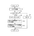
また、所定のサンプリング時間毎に、入力した各信号に基づき、図4に示すように、余剰トルク演算部8E→目標トルク制限部8F→余剰トルク変換部8Gの順に循環して処理が行われる。
【0025】
まず、余剰トルク演算部8Eでは、図5に示すような処理を行う。
すなわち、先ず、ステップS1で、車輪速センサ16FL、16FR、16RL、16RRからの信号に基づいて前輪(主駆動輪)1FL,1FRの平均車輪速から後輪1RL,1RR(従駆動輪)の平均車輪速を減算することで、前輪1FL、1FRの加速スリップ量であるスリップ速度ΔVFを求める。
【0026】
ここで、スリップ速度ΔVFの演算は、例えば、次のように行われる。
前輪1FL、1FRにおける左右輪速の平均値である平均前輪速VWf、及び後輪1RL、1RRにおける左右輪速の平均値である平均後輪速VWrを、それぞれ下記式により算出する。
VWf=(VWFL+VWFR)/2 …………(1)
VWr=(VWRL+VWRR)/2 …………(2)
次に、上記平均前輪速VWfと平均後輪速VWrとの偏差から、主駆動輪である前輪1L、1Rのスリップ速度(加速スリップ量)ΔVFを、下記(3)式により算出する。
【0027】
ΔVF=VWf−VWr …………(3)
次いで、ステップS2に移行して、上記ステップS1で求めたスリップ速度ΔVFが所定値、例えば“0”より大きい正値であるか否かを判定する。この判定結果がスリップ速度ΔVFが“0”以下即ち“0”又は負値であるときには、前輪1FL、1FRが加速スリップしていないと推定されるので、ステップS3に移行して、発電負荷トルク目標値Tgtを“0”に設定した後処理を終了して目標トルク制限部8Fの処理に移行する。
【0028】
一方、ステップS2において、スリップ速度ΔVFが“0”より大きい正値であるときには、前輪1FL、1FRが加速スリップしていると推定されるので、ステップS4に移行する。
このステップS4では、前輪1FL、1FRの加速スリップを抑えるために必要な吸収トルクTΔVFを、下記(4)式によって演算してからステップS5に移行する。この吸収トルクTΔVFは加速スリップ量に比例した量となる。
【0029】
TΔVF=K1×ΔVF …………(4)
ここで、K1は、実験などによって求めたゲインである。
ステップS5では、現在の発電機7の負荷トルクTGを、下記(5)式に基づき演算したのち、ステップS6に移行する。
Vg×Ia
TG=K2・───── …………(5)
K3×Ng
ここで、Vgは発電機7の電圧、Iaは発電機7の電機子電流、Ngは発電機7の回転速度、K2は係数、K3は効率である。
【0030】
ステップS6では、下記(6)式に基づき、余剰トルクつまり発電機7で負荷すべき発電負荷トルク目標値Tgtを求めてから処理を終了して目標トルク制限部8Fの処理に移行する。
Tgt=TG+TΔVF …………(6)
次に、目標トルク制限部8Fの処理について、図6に基づいて説明する。
【0031】
すなわち、まず、ステップS11で、発電負荷トルク目標値Tgtが、発電機7の最大負荷容量HQより大きいか否かを判定する。発電負荷トルク目標値Tgtが発電機7の最大負荷容量HQ以下と判定した場合には処理を終了する。一方、発電負荷トルク目標値Tgtが発電機7の最大負荷容量HQよりも大きいと判定した場合には、ステップS12に移行する。
【0032】
ステップS12では、発電負荷トルク目標値Tgtにおける最大負荷容量HQを越える超過トルクΔTbを下記(7)式によって求めてからステップS13に移行する。
ΔTb=Tgt−HQ …………(7)
ステップS13では、スロットルセンサ22及びエンジン回転数検出センサ23からの信号に基づいて、図7に示すエンジントルク算出マップを参照して、現在のエンジントルクTeを演算してステップS14に移行する。
【0033】
ステップS14では、下記(8)式のように、エンジントルクTeから超過トルクΔTbを減算してエンジントルク上限値TeMを演算し、求めたエンジントルク上限値TeMをエンジンコントローラ19に出力した後に、ステップS15に移行する。
TeM=Te−ΔTb …………(8)
ここで、エンジンコントローラ19では、運転者のアクセルペダル17の操作に関係なく、入力したエンジントルク上限値TeMをエンジントルクTeの上限値となるようにこのエンジントルクTeを制限する。
【0034】
ステップS15では、最大負荷容量HQを発電負荷トルク目標値Tgtに設定してから処理を終了して余剰トルク変換部8Gの処理に移行する。
次に、余剰トルク変換部8Gの処理について、図8に基づいて説明する。
まず、ステップS20で、スリップ速度ΔVFが“0”より大きいか否かを判定する。この判定結果が、ΔVF≦0であるときには加速スリップを生じていないものと判断してステップS21に移行し、電動モータ3を駆動して4輪駆動状態となっているか否かを表す作動フラグF4WD が“0”にリセットされているか否かを判定し、これが“0”にリセットされているときには余剰トルク変換処理を行うことなく処理を終了して余剰トルク演算部8Eの処理に戻り、作動フラグF4WD が“1”にセットされているときには後述するステップS23に移行する。
【0035】
一方、前記ステップS20の判定結果がΔVF>0であるときには、前輪1FL、1FRが加速スリップしているものと判断してステップS22に移行し、モータ用回転速度センサ39が検出したモータ3の回転速度Nmを入力し、そのモータ3の回転速度Nmをもとに図8中に示すモータ界磁電流目標値算出用マップを参照してモータ界磁電流目標値Ifmtを算出する。
【0036】
ここで、目標モータ界磁電流算出用マップは、自動変速機4がドライブ(D)レンジにおける最大変速比となる第1速の変速比を基準にして作成され、横軸にモータ回転速度Nmをとり、縦軸にモータ界磁電流目標値Ifmtをとり、モータ回転速度Nmが“0”から第1の設定値N1 までの間ではモータ界磁電流目標値Ifmtが予め設定された最大電流値IMAX を維持し、モータ回転速度Nmが第1の設定値N1 を超えて増加すると、これに応じてモータ界磁電流目標値Ifmtが比較的大きな傾きで減少し、モータ回転速度Nmが第1の設定値N1 より大きな第2の設定値N2 からこの第2の設定値N2 より大きい第3の設定値N3 までの間はモータ界磁電流目標値Ifmtが初期電流値IINより小さい低電流値IL を維持し、モータ回転速度Nmが第3の設定値N3 を超えて増加すると、これに応じてモータ界磁電流目標値Ifmtがより大きな傾きで減少して“0”となるように特性線L1が設定されている。
【0037】
すなわち、回転速度Nmが“0”から設定値N1 までの間は一定の所定電流値IMAX とし、直流モータ3が回転速度設定値N1 以上になった場合には、公知の弱め界磁制御方式で直流モータ3の界磁電流Ifmを小さくする。すなわち、直流モータ3が高速回転になると直流モータ3における誘起電圧の上昇によりモータトルクが低下することから、上述のように、直流モータ3の回転数Nmが所定値N1 以上になったら直流モータ3の界磁電流Ifmを小さくして誘起電圧Eを低下させることで直流モータ3に流れる電流を増加させて所要モータトルクTmを得るようにする。この結果、直流モータ3が高速回転になってもモータ誘起電圧Eの上昇を抑えてモータトルクの低下を抑制するため、所要のモータトルクTmを得ることができる。また、モータ界磁電流Ifmを所定の回転速度未満と所定の回転速度以上との2段階で制御することで、連続的な界磁電流制御に比べ電子制御回路を安価に構成することができる。
【0038】
次いで、ステップS24に移行して、ステップS23で算出したモータ界磁電流目標値Ifmtをモータ制御部8Cに出力してからステップS25に移行する。
このステップS25では、モータ回転速度Nmと、ステップS23で算出したモータ界磁電流目標値Ifmtとをもとに図8中に示したモータ誘起電圧算出用マップを参照してモータ誘起電圧Eを算出する。ここで、モータ誘起電圧算出用マップは、モータ界磁電流目標値Ifmtをパラメータとして横軸にモータ回転速度Nmをとり、縦軸にモータ誘起電圧Eをとり、モータ回転速度Nmが増加することにより、モータ誘起電圧Eが線形に増加し、モータ界磁電流目標値Ifmtが増加することによってもモータ誘起電圧Eが増加するように設定されている。
【0039】
次いで、ステップS26に移行して、4輪駆動終了条件が成立したか否かを判定する。この判定は、例えば前回のモータトルク目標値Tmt(n−1) が予め設定したモータトルク閾値TmTH以下になったか否かを判定することにより行い、Tmt(n−1) >TmTHであるときには4輪駆動終了条件が成立していないものと判断してステップS27に移行し、Tmt(n−1) ≦TmTHであるときには4輪駆動終了条件が成立したものと判断してステップS30に移行する。
【0040】
ステップS27では、上記余剰トルク演算部8Eが演算した発電負荷トルク目標値Tgtに基づき対応するモータトルク目標値Tmtを算出して、ステップS28に移行する。
ステップS28では、上記モータトルク目標値Tmt及びモータ界磁電流目標値Ifmtをもとに図9に示す電機子電流目標値算出用マップを参照して電子電流目標値Iatを算出する。この電機子電流目標値算出用マップは、モータ界磁電流目標値Ifmtをパラメータとして、横軸にモータトルク目標値Tmtをとり、縦軸に電機子電流目標値Iatをとり、モータ出力トルクTmが“0”であるときにはモータ界磁電流目標値Ifmtの値にかかわらず電機子電流目標値Iatが“0”となり、この状態からモータ出力トルクTmが増加するに応じて電機子電流目標値Iatが増加すると共に、モータ界磁電流目標値Ifmtが増加するに応じて電機子電流目標値Iatが減少し、モータ出力トルクTmが大きな値となると、モータ界磁電流目標値Ifmtが小さい方から順次に電機子電流目標値Iatが“0”に設定されるように構成されている。
【0041】
次いで、ステップS29に移行し、下記(9)式に基づき、電機子電流目標値Iat、電線9の抵抗及び直流モータ3のコイルの抵抗の合成抵抗R、及び誘起電圧Eから発電機7の電圧目標値VG を算出し、この発電機7の電圧目標値VG を発電機制御部8Aに出力した後、処理を終了して余剰トルク演算部8Eの処理に戻る。
【0042】
VG =Iat×R+E …………(9)
一方、ステップS30では、前回のモータトルク目標値Tmt(n−1) から所定減少量ΔTmtを減算した値を今回のモータトルク目標値Tmt(n) (=Tmt(n−1) −ΔTmt)として算出するモータトルク減少処理を行ってからステップS31に移行し、モータトルク目標値Tmt(n) が“0”以下となったか否かを判定し、Tmt(n) >0であるときには前記ステップS28に移行し、Tmt(n) ≦0であるときにはステップS32に移行して、作動フラグF4WD を“0”にリセットしてから処理を終了する。
【0043】
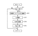
また、トラクション制御部8Tでは、図10に示すトラクション制御処理を実行する。
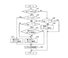
このトラクション制御処理は、所定時間(例えば10msec)毎のタイマ割込処理として実行され、先ず、ステップS41で、スリップ速度ΔVFが“0”より大きいか否かを判定し、ΔVF>0であるときには駆動輪である前輪1FL,1FRで加速スリップが発生しているものと判断して、ステップS42に移行し、トルクセンサ26から読込んだ前輪側駆動トルクTF が予め設定した駆動トルク閾値TTHより小さいか否かを判定し、TF <TTHであるときにはステップS43に移行して、自動変速機4の変速を制御する変速機コントローラ41に対して図11に示す変速マップで1速ギヤ位置から2速ギヤ位置にシフトアップするシフトアップ変速線を一点鎖線図示の実線図示の通常変速線LU より高車速側に設定された第2トラクション制御用変速線LTC2 を選択する第2TCSシフトスケジュールを設定してからステップS44に移行して、スリップ速度ΔVFを抑制するサブスロットルバルブ16のスロットル開度を設定して、これをモータコントローラ21に出力すると共に、必要に応じてエンジン2に対する燃料カット処理や前輪1FL,1FRに対して制動圧を付与する制動処理を行うトラクション制御処理を行ってからタイマ割込処理を終了する。
【0044】
また、ステップS42の判定結果がTF ≧TTHであるときにはステップS45に移行して、前述した余剰トルク変換部8Gの作動フラグF4WD が“1”にセットされている否かを判定し、これが“0”にリセットされているときにはステップS46に移行して、変速機コントローラ41に対して、図11で点線図示の通常変速線LU と第2トラクション制御用変速線LTC2 との中間の車速位置に形成された第1トラクション制御用変速線LTC1 を選択する第1TCSシフトスケジュールを設定してから前記ステップS44に移行する。
【0045】
また、ステップS45の判定結果が、作動フラグF4WD が“0”にリセットされているときには、ステップS47に移行して、第2TCSスケジュールが設定されているか否かを判定し、第2TCSスケジュールが設定されているときにはそのまま前記ステップS44に移行し、第2TCSスケジュールが設定されていないときには前記ステップS46に移行する。
【0046】
さらに、前記ステップS41の判定結果がΔVF≦0であるときには加速スリップが発生していないものと判断してステップS48に移行し、余剰トルク変換部8Gの作動フラグF4WD が“1”にセットされている否かを判定し、これが“1”にリセットされているときにはそのままタイマ割込処理を終了し、作動フラグF4WD が“0”にリセットされているときにはステップS49に移行して、変速機コントローラ41に対して、図11で実線図示の通常変速線LU を選択する通常スケジュールを設定してからタイマ割込処理を終了する。
【0047】
この図10の処理において、ステップS45、S47及びステップS48の処理がシフトスケジュール変更禁止手段に対応している。
次に、上記第1の実施形態の動作を図12に示すタイムチャートを伴って説明する。
今、自動変速機のセレクトレバーをパーキングレンジ(P)とし、イグニッションスイッチをオン状態とすることにより、エンジン2を始動させた状態で車両が停止しているものとする。
【0048】
この停止状態で、運転者が4WDスイッチ27を図12(a)に示すように時点t1でオン状態に操作すると、この時点t1では、図12(c)に示すようにセレクトレバーがパーキングレンジにあるため、4WDリレー制御部8Bでは4WDリレー31をオフ状態に制御し、4WDコントローラ8へのパワー系電源の入力が停止されていると共に、バッテリ32からの発電機7のフィールドコイルFC、ジャンクションボックス10のモータリレー36、電磁クラッチ12のクラッチコイル12aへの電力供給が停止されている。
【0049】
この停止状態から時点t2でセレクトレバーをパーキング(P)レンジからリバースレンジ(R)及びニュートラル(N)レンジを経てドライブ(D)レンジに移動させ、時点t3でドライブ(D)レンジを選択してから例えば0.05秒程度の所定時間が経過した時点t4で4WDリレー制御部8Bによって4WDリレー31が図12(b)に示すようにオン状態に制御される。
【0050】
この状態では、車両が停止状態にあるため、前輪1FL,1FRの平均前輪速VWf及び後輪1RL,1RRの平均後輪速VWrが共に“0”であり、スリップ速度ΔVFも“0”となるため、余剰トルク変換部8Gで実行される図8の処理では、イグニッションスイッチをオン状態としたときに実行される初期化処理て作動状態フラグF4WD が“0”にリセットされているので、ステップS20からステップS21を経てステップS22〜32の処理を実行することなく処理を終了して余剰トルク演算部8Eに戻ることになる。
【0051】
このため、発電機制御部8Aで発電電圧目標値VG に基づく発電機制御出力C1がオフ状態、モータ界磁出力MFもオフ状態に制御され、さらにクラッチ制御部8Dでクラッチ制御出力CLがオフ状態に制御される。したがって、発電機7での発電及び直流モータ3の駆動が停止されていると共に、クラッチ12が非締結状態に制御される。
【0052】
この状態から時点t5でアクセルペダル17を大きく踏込んで車両を急発進させたり、アクセルペダル17を大きく踏込まなくても降雨路、雪路、凍結路のような低摩擦係数路面で前進方向に発進させることにより、主駆動輪となる前輪1FL,1FRに加速スリップを生じると、前後の車輪速差が生じることにより、スリップ速度ΔVFが正の値となる。
【0053】
このとき、クラッチ制御部8Dでクラッチ制御出力CLが所定のデューティ比に制御されて電磁クラッチ12が締結状態となり、これと同時に余剰トルク演算部8Eにおける図5の処理で、スリップ速度ΔVFが正値となるので、ステップS2からステップS4に移行し、スリップ速度ΔVFにゲインK1を乗算して加速スリップを抑えるために必要な吸収トルクTΔVFを算出し、次いで、現在の発電電圧VG 、電機子電流Ia、発電機回転数Ngに基づいて前記(5)式の演算を行って現在の発電負荷トルクTGを算出する(ステップS5)。この現在の発電負荷トルクTGは、発進時には発電機回転数Ngが比較的小さいので、発電電圧VG 及び電機子電流Iaの増加に応じて増加する。さらに、吸収トルクTΔVFと現在の発電負荷トルクTGとを乗算して発電負荷トルク目標値Tgtを算出するので、この発電負荷トルク目標値Tgtも増加する。
【0054】
ところで、発電機7で発生させる発電電圧VG は、余剰トルク変換部8Gの図8の処理で制御されることになるが、スリップ速度ΔVFが正値となっているので、ステップS22に移行して、作動フラグF4WD が“1”にセットされ、次いでステップS23に移行して、モータトルク目標値Tmtとモータ界磁電流目標値Ifmtとをもとに図9の電機子電流目標値算出用マップを参照して算出される電機子電流目標値Iatに線路抵抗Rを乗算した電圧値と直流モータ3での誘起電圧Eとを加算して算出される。
【0055】
ここで、モータ界磁電流目標値Ifmtは、モータ回転速度Nmをもとに図8の処理におけるステップS23でモータ界磁電流目標値算出用マップを参照して算出されるが、車両の発進時にはモータ回転速度Nmがまだ低いため、このときのモータ界磁電流目標値Ifmtが最大電流IMAX に設定される。
そして、算出されたモータ界磁電流目標値Ifmtがそのままモータ制御部8Cに出力されることにより、直流モータ3が駆動開始される(ステップS24)。
【0056】
このとき、ステップS25で算出されるモータ誘起電圧Eも増加するため、ステップS27で算出される電機子電流目標値Iatが時間の経過と共に上昇し、モータトルクTmは図12(f)に示すように増加して、これが後輪1RL,1RRに伝達されることにより、これら後輪1RL,1RRが駆動開始される。このとき、クラッチ制御部8Dによって電磁クラッチ12も締結状態に制御される。
【0057】
この結果、急発進時又は低摩擦係数路面での発進時に主駆動輪となる前輪1FL,1FRで加速スリップを生じた場合に、これを解消するように従駆動輪となる後輪1RL,1RRを直流モータ3が前輪1FL,1FRでの加速スリップを解消するように駆動されることになり、円滑な発進を行うことができる。
この間、トラクション制御部8Tでは、イグニッションスイッチがオン状態となった時点で行われる初期化処理で変速機コントローラ41に対するシフトスケジュールが通常シフトスケジュールに設定されており、スリップ速度ΔVFがスリップ速度閾値ΔVFTHを越えていないので、ステップS41からステップS48に移行し、作動フラグF4WD が“1”にセットされてもそのまま通常シフトスケジュールの設定状態が継続される。
【0058】
その後、時点t6で、スリップ速度ΔVFがスリップ速度閾値ΔVFTHを越えると、トラクション制御部8Tにおける図10の処理で、ステップS41からステップS42に移行し、前輪側駆動トルクTF がドライブ(D)レンジを選択した時点t3で図12(i)に示すように駆動トルク閾値TTHを越えているので、ステップS45に移行する。ここで、作動フラグF4WD が“1”にセットされているので、ステップS47に移行し、通常シフトスケジュールが設定されており、第2TCSシフトスケジュールが設定されていないので、ステップS46に移行して、変速機コントローラ41に対して第1TCSシフトスケジュールが設定される。その後、ステップS44に移行して、サブスロットルバルブ16のスロットル開度が減少制御されると共に、必要に応じてエンジン2に対して燃料カット処理、駆動輪となる前輪1FL,1FRに対する制動力の付与が行われて、図12(d)で点線図示のように前輪側の加速スリップが抑制され、スリップ速度閾値ΔVFTH分だけ実線図示の後輪側車速より高い状態で加速が行われる。
【0059】
その後、モータトルクTmは図12(f)に示すように急増した後ほぼ一定値に制御され、その後、雪路、凍結路等の比較的路面摩擦係数が小さい路面を走行することにより、前輪側駆動トルクTF が徐々に減少して、時点t7で、駆動トルク閾値TTH未満に低下すると、図10の処理で、ステップS42からステップS43に移行して、変速機コントローラ41に対して第2TCSシフトスケジュールが設定され、自動変速機4での1速ギヤ位置から2速ギヤ位置へのアップシフト変速線がより高車速側に変更される。
【0060】
その後、時点t8で、前輪側の加速スリップが収まって、スリップ速度ΔVFがスリップ速度閾値ΔVF以下となると、ステップS41からステップS48に移行するが、作動フラグF4WD が“1”にセットされた状態を継続するで、シフトスケジュールは図12(g)に示すように第2TCSシフトスケジュールを維持する。
【0061】
その後、時点t9で前輪1FL,1FRと後輪1RL,1RRの車輪速がほぼ一致すると、スリップ速度ΔVFが“0”となり、図8の処理でステップS20からステップS21に移行するが、作動フラグF4WD が“1”にセットされているので、ステップS23に移行して、電動モータ3の制御状態が継続される。
その後、時点t10で、モータトルク目標値Tmtがモータトルク閾値Th以下となると、4輪駆動終了条件が成立することにより、図8の処理でステップS26からステップS30に移行して、モータトルク減少処理が行われることにより、モータトルク目標値Tmtが所定減少値ΔTmtずつ順次減少されて、これに応じてモータトルクTmも一定勾配で減少し、時点t11でモータトルク目標値Tmtが“0”以下となるとステップS32に移行して作動フラグF4WD が“0”にリセットされて、ステップS21からそのまま処理を終了する。
【0062】
このように、作動フラグF4WD が“0”にリセットされると、図10のトラクション制御処理で、ステップS48からステップS49に移行して、通常シフトスケジュールに復帰される。
この結果、上記実施形態によると、トラクション制御が開始されることにより、変速機コントローラ41のシフトスケジュールが通常シフトスケジュールにおける1速ギヤ位置から2速ギヤ位置にシフトアップする通常変速線LU がこれより高車速側の第1TCSシフトスケジュールで設定された第1トラクション制御変速線LTC1 に変更され、さらに路面摩擦抵抗が小さいときに、第1トラクション制御変速線LTC1 よりさらに高車速側の第2TCSシフトスケジュールで設定された第2トラクション制御変速線LTC2 に変更されることにより、第2速ギヤ位置へのアップシフトが抑制されて、良好なトラクション制御を行うことができる。
【0063】
ところが、トラクション制御は、スリップ速度ΔVFがスリップ速度閾値ΔVFTH以下に低下したときに制御を終了して、変速機コントローラ41のシフトスケジュールを通常シフトスケジュールに戻すことになるが、電動モータ3を駆動する図8のトルク変換処理は、スリップ速度ΔVFが“0”となってもモータトルク目標値Tmtがモータトルク閾値Th以下となって初めて4輪駆動終了条件が終了することになり、トラックション制御の終了後も制御を継続する。このトラクション制御の終了後のトルク変換処理で、シフトスケジュールが通常シフトスケジュールへの復帰を禁止して第2TCSシフトスケジュールを維持するので、アクセル開度が低く車速が通常変速線LU と第2TSC変速線LTC2 との間にある場合でも、第2ギヤ位置へのシフトアップが行われず、第1ギヤ位置を維持するので、エンジン回転速度Neが低下することなく、発電機7での発電能力を維持することができ、駆動モータ3正確なトルク制御を行うことができる。
【0064】
これに対して、図11(d)で点線図示のように、トラクション制御の終了時点でシフトスケジュールが通常シフトスケジュールに復帰する場合には、低アクセル開度で車速が通常変速線LU と第2TCS変速線LTC2 との間の車速である場合には、自動変速機4が第1速ギヤ位置から第2速ギヤ位置にアップシフトされることにより、エンジン回転速度Neが低下し、これに応じて発電機7の発電量が低下することにより、発電機7で電動モータ3で必要とする電機子電流Iaを確保するために必要な発電量を確保できない発電不足が発生するか、最悪の状態では発電機の発電量が電動モータの逆起電力を下回って発電不能状態となり、電動モータ3で必要とするモータトルクを発生することができない制御不良状態となる問題がある。
【0065】
しかしながら、上記実施形態では、電動モータ3に対するトルク制御が継続している間、通常変速線LU より高車速側の変速線に設定されたシフトスケジュールを通常変速線LU 側に戻すシフトスケジュールの変更が禁止されているので、自動変速機4で第2速ギヤ位置へのアップシフトを確実に防止して、第1速ギヤ位置を保持するので、発電機7での発電不足が発生することを確実に防止することができる。
【0066】
また、上記実施形態では、雪路、凍結路等の路面摩擦係数が小さい路面を走行する状態となって、シフトスケジュールが第2TCSシフトスケジュールまで変更する場合について説明したが、降雨路等の路面摩擦係数が中程度に小さい路面を走行する場合には、前輪駆動トルクTF の減少量が少なくなって、駆動トルク閾値TTH未満に低下することがなく、第1TCSシフトスケジュールを維持することになり、この場合もトラクション制御が終了した時点で通常シフトスケジュールに戻ることが禁止される。さらに、前輪駆動トルクTF が駆動トルク閾値TTH未満に低下した後に、中程度に摩擦係数が小さい路面を走行する状態となって前輪駆動トルクTF が再度駆動トルク閾値TTHを越える状態となった場合は、図10の処理において、ステップS42からステップS45に移行するが、作動フラグF4WD が“1”にセットされており、さらにシフトスケジュールが前回まで第2TCSシフトスケジュールに設定されているので、ステップS47からステップS46に移行することなく直接ステップS44に移行することになり、第2TCS変速線LTC2 が第1TCS変速線LTC1 に復帰することが禁止され、自動変速機4が第1速ギヤ位置から第2速ギヤ位置へシフトアップされることを確実に禁止することができる。
【0067】
なお、上記実施形態においては、自動変速機4を適用した場合について説明した場合について説明したが、これに限定されるものではなく、ベルト式無段変速機やトロイダル型無段変速機等の無段変速機を適用するようにしてもよい。この場合には、無段変速機の入力側回転速度及び出力側回転速度を検出することにより無段変速機の変速比を検出し、この変速比が小さくなる方向へのシフトを禁止するようにすればよい。
【0068】
また、上記実施形態においては、電機子電流目標値Iatとモータ誘起電圧Eとに基づいて発電機7の発電電圧VG を算出し、この発電電圧VG に基づいて発電機7の界磁制御出力MFを制御する場合について説明したが、これに限定されるものではなく、電機子電流目標値Iatと電流センサ37で検出した直流モータ3に供給される実際の電機子電流Iaとの偏差ΔIaに比例制御ゲインを乗算するか、偏差ΔIaの積分値に積分制御ゲインを乗算して発電機界磁電流Ifgを算出し、この発電機界磁電流Ifgに応じたデューティ比を算出し、このデューティ比の制発電制御出力をパイポーラトランジスタ33に供給するようにしてもよい。
【0069】
さらに、上記実施形態においては、クラッチとして電磁クラッチ12を適用した場合について説明したが、これに限定されるものではなく、流体圧クラッチを適用することもでき、この場合には流体圧クラッチに供給する流体圧を制御する圧力制御弁を電気的に制御することにより、クラッチ締結力を制御すればよく、その他クラッチ締結力を電気的制御が可能な任意のクラッチを適用することができる。
【0070】
さらにまた、上記実施形態においては、発電機7の入力軸をベルト6を介してエンジン2に連結した場合について説明したが、これに限定されるものではなく、発電機7の入力軸をトランスファの出力側から前輪1FL,1FRまでの回転部分に連結するようにしてもよく、この場合には、エンジン2のアイドリング時の負荷を減少させることができる。
【0071】
なおさらに、上記実施形態においては、モータ回転数検出手段としてモータ回転速度センサ39を適用し、このモータ回転速度センサ39でモータ回転速度Nmを直接検出する場合について説明したが、これに限定されるものではなく、車輪速センサ24RL及び24RRで検出した車輪速VwRL及びVwRRとディファレンシャルギヤ13の減速比とに基づいてモータ回転速度を推定するようにしてもよい。
【0072】
また、上記実施形態においては、前輪の加速スリップに応じて4輪駆動状態に移行する場合について説明したが、これに限定されるものではなく、アクセル開度などに応じて4輪駆動状態に移行するようにしてもよい。
さらに、上記実施形態においては、前輪1FL,1FRを主駆動輪とし、後輪1RL,1RRを従駆動輪とする4輪駆動車に本発明を適用した場合について説明したが、これに限定されるものではなく、後輪1RL,1RRを主駆動輪とし、前輪1FL,1FRを従駆動輪とするようにしてもよい。
【0073】
さらにまた、上記実施形態においては、本発明を4輪駆動車に適用した場合について説明したが、これに限定されるものではなく、前後方向に2輪以上の駆動輪を備え、一部の主駆動輪を内燃機関で駆動し、残りの従駆動輪を電動機で駆動する場合に本発明を適用することができ、その他内燃機関等の回転駆動源によって回転駆動される発電機によって車輪を駆動する電動機を駆動する電動式駆動装置に本発明を適用することができる。
【図面の簡単な説明】
【図1】本発明の第1実施形態を示す概略装置構成図である。
【図2】第1実施形態における制御系のブロック図である。
【図3】第1実施形態に係る4WDコントローラを示す機能ブロック図である。
【図4】第1の実施形態における4WDコントローラでの制御処理手順を示すフローチャートである。
【図5】第1の実施形態における余剰トルク演算部の処理手順の一例を示すフローチャートである。
【図6】第1の実施形態における目標トルク制御部の処理手順の一例を示すフローチャートである。
【図7】エンジン回転速度Neをパラメータとしてスロットル開度θとエンジントルクTeとの関係を示すエンジントルク算出マップを示す図である。
【図8】第1の実施形態における余剰トルク変換部の処理手順の一例を示すフローチャートである。
【図9】モータ界磁電流目標値をパラメータとしてモータトルク目標値と電機子電流目標値との関係を示す電機子電流目標値算出マップを示す図である。
【図10】実施形態におけるトラクション制御部の処理手順の一例を示すフローチャートである。
【図11】変速マップを示す説明図である。
【図12】実施形態の動作の説明に供するタイムチャートである。
【図13】発電能力線とモータ逆起電力との関係を示す特性線図である。
【符号の説明】
1FL,1FR 前輪
1RL,1RR 後輪
2 エンジン
3 直流モータ
4 自動変速機
7 発電機
8 4WDコントローラ
10 ジャンクションボックス
11 減速機
12 電磁クラッチ
23 エンジン回転速度センサ
24FL〜24RR 車輪速センサ
25 シフト位置センサ
FC フィールドコイル
SC ステータコイル
37 電流センサ
39 モータ用回転速度センサ[0001]
TECHNICAL FIELD OF THE INVENTION
The present invention relates to a vehicle driving force control device that drives an electric motor that transmits driving torque to driven wheels with electric power generated by a generator.
[0002]
[Prior art]
As a driving force control device for this kind of vehicle, one of the front wheels and the rear wheels is driven as a main drive wheel by a power of an internal combustion engine via a transmission, and the other of the front wheels and the rear wheels is driven by an electric motor. The generator is driven by the driving force of the internal combustion engine, and the electric power generated by the generator is supplied to the electric motor. When the accelerator pedal is depressed and the vehicle speed is equal to or lower than the set value, the electric motor is operated to drive the front wheels and the rear wheels. BACKGROUND ART A front-rear wheel drive vehicle that drives wheels has been proposed (for example, see Patent Document 1).
[0003]
[Patent Document 1]
Japanese Utility Model Publication No. 55-138129 (page 1, FIG. 2)
[0004]
[Problems to be solved by the invention]
However, in Patent Document 1, the electric motor is driven by the electric power generated by the electric generator driven by the internal combustion engine, so that the electric generator generates power unless it overcomes the back electromotive force of the electric motor. Can not. That is, as shown in FIG. 13, when the horizontal axis indicates the engine rotation speed and the vertical axis indicates the voltage, the power generation capacity line of the generator is “0” as shown by the solid line when the engine rotation speed is “0”. 0 ", and when the engine speed is increased, the rate of increase is small when the engine speed is low, and thereafter the rate of increase is increased as the vehicle speed increases. Is represented by a straight line that is "0" when the engine rotation speed is "0" as shown by a broken line, and thereafter increases at a constant increase rate as the engine rotation speed increases. For this reason, when the engine rotation speed is between "0" and the predetermined engine rotation speed Ves, the power generation capacity line of the generator is lower than the back electromotive force of the motor, and the generator cannot flow the generation current. However, when the motor cannot generate the driving torque, when the engine rotation speed exceeds the predetermined engine rotation speed Ves, the generated current of the generator increases accordingly, and the driving torque may be generated by the motor. it can.
[0005]
By the way, in Patent Document 1, a transmission (transmission) is provided on the output side of the internal combustion engine, and the rotation speed of the internal combustion engine changes according to the transmission gear ratio when the vehicle speed is constant. The amount of power generated by the generator driven by the internal combustion engine changes according to the rotation speed of the internal combustion engine.
On the other hand, in vehicles equipped with a traction control device in order to prevent acceleration slip of the drive wheels, the first-speed gear of the automatic transmission is used when an acceleration slip occurs in the drive wheels, such as when starting on a road with a low friction coefficient. The upshift shift line that shifts up from the position to the second gear position is shifted to a higher vehicle speed side with respect to the normal shift line. The shift schedule is changed to suppress the upshift of the automatic transmission, and the throttle opening and fuel cut. Thus, control to prevent acceleration slip is performed by lowering the engine rotation speed and applying a braking force to the drive wheels.
[0006]
As described above, in the traction control device, the shift schedule is changed so as to suppress the shift-up while the acceleration slip occurs, and when the acceleration slip is eliminated, the shift schedule returns to the original shift schedule using the normal shift line. Will be. For this reason, in a vehicle equipped with a traction control device, when the electric motor is driven by the amount of power generated by the generator, the first-speed gear is used during the acceleration slip even if the vehicle speed exceeds the normal shift line. Since the shift-up from the position to the second gear position is suppressed, the engine speed becomes relatively high, and the amount of power generated by the generator overcomes the back electromotive force of the motor to supply the generated current to the motor. However, if the acceleration slip is eliminated in this motor driving state, the shift to the shift schedule using the original normal shift line is resumed. There is an unsolved problem that the rotation speed may decrease and the power generation may be insufficient or power generation may not be possible.
[0007]
Therefore, the present invention has been made by focusing on the unsolved problem of the above-described conventional example, and provides a driving force control device for a vehicle that can prevent an insufficient power generation state or a power generation impossible state in a generator. It is aimed at.
[0008]
[Means for Solving the Problems]
In order to achieve the above object, a driving force control device for a vehicle according to the present invention includes a main driving source that drives a main driving wheel via a transmission capable of changing a shift schedule, and is driven by the main driving source. A driving force control apparatus for a vehicle, comprising: a generator; and a motor driven by the power of the generator and capable of transmitting a driving torque to a driven wheel. And a shift schedule change prohibiting unit that prohibits a change in the shift schedule that causes the generator to generate insufficient power in a driving state in which the driving torque is transmitted to the generator.
[0009]
【The invention's effect】
According to the present invention, in a driving state such as a four-wheel driving state in which a driving torque is generated with respect to a driven wheel by an electric motor, a shift schedule change prohibiting unit is used to change a shift schedule that causes a power generation shortage in a generator. For example, when the shift schedule is changed to a higher vehicle speed side than the normal shift line by a traction control device or the like, the shift schedule is maintained, and the rotational speed of the main drive source decreases due to the shift up of the transmission. That is, the power generation amount of the generator can be secured to an appropriate value, and the effect of appropriately controlling the driving torque of the electric motor can be obtained.
[0010]
BEST MODE FOR CARRYING OUT THE INVENTION
Next, an embodiment of the present invention will be described with reference to the drawings.
FIG. 1 is a schematic configuration diagram showing an embodiment in which the present invention is applied to a four-wheel drive vehicle. Left and right front wheels 1FL and 1FR as main drive wheels are driven by an
[0011]
The output torque Te of the
The
[0012]
A main throttle valve 15 and a
[0013]
The opening of the
[0014]
The
[0015]
Further, as shown in FIG. 2, the
The field coil FC has one end connected to the output side of the
[0016]
Here, a system that supplies the field current Ifg via the
The 4WD relay 31 has one end of a relay coil connected to the output side of an
[0017]
The
[0018]
A
[0019]
Further, in the DC motor 3, the field current Ifm is controlled by a pulse width modulated field control command as a motor output torque command from the
[0020]
The
[0021]
As shown in FIG. 3, the
The generator control unit 8A adjusts the field current Ifg of the
[0022]
The relay control unit 8B controls disconnection and connection of power supply from the
The motor control unit 8C adjusts the torque of the DC motor 3 to a required value by adjusting the field current Ifm of the DC motor 3 based on the target motor field current Ifmt calculated by the surplus
[0023]
The clutch control unit 8D calculates a corresponding motor torque target value Tmt based on a power generation load torque target value Tgt calculated by a surplus
[0024]
TCL= Tmt × KDEF× KTM+ TCL0
Where KDEFIs the reduction ratio of the
Further, at every predetermined sampling time, based on each input signal, as shown in FIG. 4, the processing is performed by circulating in the order of the surplus
[0025]
First, the surplus
That is, first, in step S1, based on the signals from the wheel speed sensors 16FL, 16FR, 16RL, 16RR, the average wheel speeds of the front wheels (main drive wheels) 1FL, 1FR are calculated from the average wheel speeds of the rear wheels 1RL, 1RR (slave drive wheels). By subtracting the wheel speed, a slip speed ΔVF, which is an acceleration slip amount of the front wheels 1FL and 1FR, is obtained.
[0026]
Here, the calculation of the slip speed ΔVF is performed, for example, as follows.
The average front wheel speed VWf, which is the average value of the left and right wheel speeds at the front wheels 1FL, 1FR, and the average rear wheel speed VWr, which is the average value of the left and right wheel speeds at the rear wheels 1RL, 1RR, are calculated by the following equations.
VWf = (VWFL+ VWFR) / 2 ... (1)
VWr = (VWRL+ VWRR) / 2 ………… (2)
Next, from the deviation between the average front wheel speed VWf and the average rear wheel speed VWr, the slip speed (acceleration slip amount) ΔVF of the
[0027]
ΔVF = VWf−VWr (3)
Next, the process proceeds to step S2, and it is determined whether or not the slip speed ΔVF obtained in step S1 is a positive value greater than a predetermined value, for example, “0”. If the result of this determination is that the slip speed ΔVF is equal to or less than “0”, that is, “0” or a negative value, it is estimated that the front wheels 1FL and 1FR have not accelerated and slipped. After the value Tgt is set to “0”, the process is terminated, and the process proceeds to the process of the target
[0028]
On the other hand, if the slip speed ΔVF is a positive value greater than “0” in step S2, it is estimated that the front wheels 1FL and 1FR are slipping due to acceleration, and the process proceeds to step S4.
In this step S4, the absorption torque TΔVF necessary for suppressing the acceleration slip of the front wheels 1FL, 1FR is calculated by the following equation (4), and then the process proceeds to step S5. This absorption torque TΔVF is an amount proportional to the acceleration slip amount.
[0029]
TΔVF = K1 × ΔVF (4)
Here, K1 is a gain obtained by an experiment or the like.
In step S5, after the current load torque TG of the
Vg × Ia
TG = K2 · ───── (5)
K3 × Ng
Here, Vg is the voltage of the
[0030]
In step S6, the surplus torque, that is, the power generation load torque target value Tgt to be loaded by the
Tgt = TG + TΔVF (6)
Next, the processing of the target
[0031]
That is, first, in step S11, it is determined whether the power generation load torque target value Tgt is larger than the maximum load capacity HQ of the
[0032]
In step S12, the excess torque ΔTb exceeding the maximum load capacity HQ at the power generation load torque target value Tgt is obtained by the following equation (7), and the process proceeds to step S13.
ΔTb = Tgt−HQ (7)
In step S13, the current engine torque Te is calculated based on the signals from the
[0033]
In step S14, the engine torque upper limit TeM is calculated by subtracting the excess torque ΔTb from the engine torque Te as shown in the following equation (8), and the calculated engine torque upper limit TeM is output to the
TeM = Te−ΔTb (8)
Here, the
[0034]
In step S15, after setting the maximum load capacity HQ to the power generation load torque target value Tgt, the process ends, and the process proceeds to the surplus
Next, the processing of the
First, in step S20, it is determined whether the slip speed ΔVF is greater than “0”. If the determination result is ΔVF ≦ 0, it is determined that no acceleration slip has occurred, and the flow shifts to step S21 to operate the electric motor 3 to indicate whether or not the vehicle is in the four-wheel drive state.4WDIs determined to be "0". If the flag is reset to "0", the process is terminated without performing the surplus torque conversion process, and the process returns to the process of the surplus torque calculation unit 8E. F4WDIs set to "1", the flow shifts to step S23 described later.
[0035]
On the other hand, if the result of the determination in step S20 is ΔVF> 0, it is determined that the front wheels 1FL and 1FR are accelerating and slipping, and the process proceeds to step S22, where the rotation of the motor 3 detected by the motor
[0036]
Here, the target motor field current calculation map is created based on the first speed ratio, which is the maximum speed ratio in the drive (D) range of the automatic transmission 4, and the horizontal axis indicates the motor rotation speed Nm. The vertical axis indicates the motor field current target value Ifmt, and the motor rotation speed Nm changes from "0" to the first set value N.1Until the motor field current target value Ifmt reaches the preset maximum current value I.MAXIs maintained, and the motor rotation speed Nm is set to the first set value N1, The motor field current target value Ifmt decreases correspondingly with a relatively large gradient, and the motor rotation speed Nm decreases to the first set value N.1Larger second set value N2From the second set value N2Third set value N greater than3Until the motor field current target value Ifmt is equal to the initial current value IINSmaller low current value ILIs maintained, and the motor rotation speed Nm is changed to the third set value N3, The characteristic line L1 is set such that the motor field current target value Ifmt decreases with a larger slope and becomes “0” in response to the increase.
[0037]
That is, when the rotation speed Nm is changed from “0” to the set value N1Until the predetermined predetermined current value IMAXAnd the DC motor 3 is set to the rotation speed set value N.1In the above case, the field current Ifm of the DC motor 3 is reduced by a known field weakening control method. That is, when the DC motor 3 rotates at a high speed, the motor torque decreases due to an increase in the induced voltage in the DC motor 3, and as described above, the rotational speed Nm of the DC motor 3 is increased to the predetermined value N.1When the above occurs, the field current Ifm of the DC motor 3 is reduced to lower the induced voltage E, thereby increasing the current flowing through the DC motor 3 and obtaining the required motor torque Tm. As a result, even if the DC motor 3 rotates at a high speed, the required motor torque Tm can be obtained because the increase in the motor induced voltage E is suppressed and the decrease in the motor torque is suppressed. Further, by controlling the motor field current Ifm in two stages, that is, less than the predetermined rotation speed and higher than the predetermined rotation speed, the electronic control circuit can be configured at a lower cost as compared with continuous field current control.
[0038]
Next, the process shifts to step S24 to output the motor field current target value Ifmt calculated in step S23 to the motor control unit 8C, and then shifts to step S25.
In step S25, the motor induced voltage E is calculated based on the motor rotation speed Nm and the motor field current target value Ifmt calculated in step S23 with reference to the motor induced voltage calculation map shown in FIG. I do. Here, the motor induced voltage calculation map is obtained by taking the motor rotational speed Nm on the horizontal axis and the motor induced voltage E on the vertical axis using the motor field current target value Ifmt as a parameter, and increasing the motor rotational speed Nm. The motor induced voltage E is set so that the motor induced voltage E increases linearly and the motor field current target value Ifmt increases.
[0039]
Next, the process proceeds to step S26 to determine whether the four-wheel drive end condition is satisfied. This determination is made, for example, by setting the previous motor torque target value Tmt (n-1) −1 to a preset motor torque threshold value Tm.THTmt (n−1) 以下> TmTHWhen it is determined that the four-wheel drive end condition is not satisfied, the process proceeds to step S27, and Tmt (n−1) ≦ TmTHIf it is, it is determined that the four-wheel drive end condition has been satisfied, and the routine goes to Step S30.
[0040]
In step S27, a corresponding motor torque target value Tmt is calculated based on the power generation load torque target value Tgt calculated by the surplus
In step S28, the electronic current target value Iat is calculated based on the motor torque target value Tmt and the motor field current target value Ifmt with reference to the armature current target value calculation map shown in FIG. This armature current target value calculation map uses the motor field current target value Ifmt as a parameter, takes the motor torque target value Tmt on the horizontal axis, takes the armature current target value Iat on the vertical axis, and calculates the motor output torque Tm. When “0”, the armature current target value Iat becomes “0” regardless of the value of the motor field current target value Ifmt. As the motor output torque Tm increases from this state, the armature current target value Iat increases. When the motor field current target value Ifmt increases and the armature current target value Iat decreases as the motor output torque Tm increases, the motor field current target value Ifmt increases in order from the smaller one. The configuration is such that the armature current target value Iat is set to “0”.
[0041]
Next, the process proceeds to step S29, and based on the following equation (9), the voltage of the
[0042]
VG= Iat × R + E (9)
On the other hand, in step S30, a value obtained by subtracting the predetermined decrease amount ΔTmt from the previous motor torque target value Tmt (n-1) is set as the current motor torque target value Tmt (n) (= Tmt (n-1) -ΔTmt). After performing the calculated motor torque reduction process, the process shifts to step S31 to determine whether or not the motor torque target value Tmt (n) n is equal to or less than “0”. When Tmt (n)> 0, the process proceeds to step S28. When Tmt (n) ≦ 0, the process proceeds to step S32 and the operation flag F4WDIs reset to "0", and the process is terminated.
[0043]
Further, the traction control unit 8T executes the traction control process shown in FIG.
This traction control process is executed as a timer interrupt process at predetermined time intervals (for example, 10 msec). First, in step S41, it is determined whether the slip speed ΔVF is greater than “0”. It is determined that acceleration slip has occurred in the front wheels 1FL and 1FR, which are the drive wheels, and the process proceeds to step S42 to read the front wheel drive torque T read from the torque sensor 26.FIs the drive torque threshold T set in advanceTHIt is determined whether or not T is smaller thanF<TTHIn step S43, the process proceeds to step S43, where the
[0044]
Further, when the determination result of step S42 is TF≧ TTH, The process proceeds to step S45, where the operation flag F of the surplus
[0045]
Also, the result of the determination in step S45 is that the operation flag F4WDIs reset to "0", the flow shifts to step S47 to determine whether or not the second TCS schedule is set. If the second TCS schedule is set, the flow shifts to step S44 as it is, When the 2TCS schedule has not been set, the process proceeds to step S46.
[0046]
Further, when the determination result in step S41 is ΔVF ≦ 0, it is determined that no acceleration slip has occurred, and the flow shifts to step S48 to set the operation flag F of the surplus torque conversion unit 8G.4WDIs set to "1", and when it is reset to "1", the timer interrupt processing is terminated as it is and the operation flag F4WDIs reset to "0", the routine proceeds to step S49, where the
[0047]
In the process of FIG. 10, the processes of steps S45, S47, and S48 correspond to shift schedule change prohibition means.
Next, the operation of the first embodiment will be described with reference to a time chart shown in FIG.
Now, it is assumed that the vehicle is stopped with the
[0048]
In this stopped state, when the driver operates the
[0049]
At time t2 from the stop state, the select lever is moved from the parking (P) range to the drive (D) range through the reverse range (R) and the neutral (N) range, and at time t3, the drive (D) range is selected. At time t4 when a predetermined time of, for example, about 0.05 seconds elapses, the 4WD relay controller 8B controls the 4WD relay 31 to the ON state as shown in FIG. 12B.
[0050]
In this state, since the vehicle is stopped, the average front wheel speed VWf of the front wheels 1FL, 1FR and the average rear wheel speed VWr of the rear wheels 1RL, 1RR are both "0", and the slip speed ΔVF is also "0". Therefore, in the process of FIG. 8 executed by the surplus
[0051]
For this reason, the power generation voltage target value VG, The motor control output C1 is turned off, the motor field output MF is also turned off, and the clutch control output CL is turned off by the clutch control unit 8D. Therefore, the power generation by the
[0052]
From this state, at time t5, the vehicle is suddenly started by depressing the accelerator pedal 17 greatly, or the vehicle is started in the forward direction on a low friction coefficient road surface such as a rainy road, a snowy road, or a frozen road without depressing the accelerator pedal 17 greatly. As a result, when an acceleration slip occurs in the front wheels 1FL and 1FR serving as the main drive wheels, a difference in front and rear wheel speed occurs, and the slip speed ΔVF becomes a positive value.
[0053]
At this time, the clutch control output CL is controlled to a predetermined duty ratio by the clutch control unit 8D, and the
[0054]
By the way, the generated voltage V generated by the
[0055]
Here, the motor field current target value Ifmt is calculated based on the motor rotation speed Nm by referring to the motor field current target value calculation map in step S23 in the process of FIG. 8, but when the vehicle starts moving. Since the motor rotation speed Nm is still low, the motor field current target value Ifmt at this time isMAXIs set to
Then, the calculated motor field current target value Ifmt is output to the motor control unit 8C as it is, so that the driving of the DC motor 3 is started (step S24).
[0056]
At this time, since the motor induced voltage E calculated in step S25 also increases, the armature current target value Iat calculated in step S27 increases with the passage of time, and the motor torque Tm becomes as shown in FIG. , And this is transmitted to the rear wheels 1RL, 1RR, so that the driving of the rear wheels 1RL, 1RR is started. At this time, the clutch control unit 8D also controls the electromagnetic clutch 12 to the engaged state.
[0057]
As a result, when an acceleration slip occurs in the front wheels 1FL and 1FR serving as the main drive wheels at the time of a sudden start or a start on a road surface with a low friction coefficient, the rear wheels 1RL and 1RR serving as the slave drive wheels are removed so as to eliminate this. The DC motor 3 is driven so as to eliminate the acceleration slip at the front wheels 1FL and 1FR, so that a smooth start can be performed.
During this time, in the traction control unit 8T, the shift schedule for the
[0058]
Thereafter, at time t6, the slip speed ΔVF becomes the slip speed threshold value ΔVF.THIs exceeded, the traction control unit 8T shifts from step S41 to step S42 in the processing of FIG.FAt the time point t3 when the drive (D) range is selected, as shown in FIG.TH, The process proceeds to step S45. Here, the operation flag F4WDIs set to "1", the process shifts to step S47, the normal shift schedule is set, and the second TCS shift schedule is not set, so the process shifts to step S46 and the
[0059]
After that, the motor torque Tm is controlled to a substantially constant value after rapidly increasing as shown in FIG. 12 (f), and thereafter the vehicle is driven on a relatively low road surface friction coefficient such as a snowy road or an icy road, so that the front wheel side Drive torque TFGradually decreases, and at time t7, the driving torque threshold TTHWhen it is reduced to less than 2, the process proceeds from step S42 to step S43 in the processing of FIG. 10, the second TCS shift schedule is set for the
[0060]
Thereafter, at time t8, when the acceleration slip on the front wheel side is stopped and the slip speed ΔVF becomes equal to or lower than the slip speed threshold value ΔVF, the process proceeds from step S41 to step S48.4WDContinues to be set to “1”, the shift schedule maintains the second TCS shift schedule as shown in FIG.
[0061]
Thereafter, when the wheel speeds of the front wheels 1FL, 1FR and the rear wheels 1RL, 1RR substantially coincide with each other at time t9, the slip speed ΔVF becomes “0”, and the process proceeds from step S20 to step S21 in the processing of FIG.4WDIs set to "1", the process proceeds to step S23, and the control state of the electric motor 3 is continued.
Thereafter, at time t10, when the motor torque target value Tmt becomes equal to or less than the motor torque threshold Th, the four-wheel drive end condition is satisfied, so that the process proceeds from step S26 to step S30 in the process of FIG. Is performed, the motor torque target value Tmt is sequentially reduced by the predetermined decrease value ΔTmt, and accordingly, the motor torque Tm also decreases at a constant gradient. At the time t11, the motor torque target value Tmt becomes “0” or less. Then, the process proceeds to step S32 and the operation flag F4WDIs reset to "0", and the process ends as it is from step S21.
[0062]
Thus, the operation flag F4WDIs reset to "0", in the traction control process of FIG. 10, the process shifts from step S48 to step S49 to return to the normal shift schedule.
As a result, according to the above embodiment, when the traction control is started, the shift schedule of the
[0063]
However, in the traction control, the slip speed ΔVF is changed to the slip speed threshold value ΔVF.THWhen it falls below, the control is terminated and the shift schedule of the
[0064]
On the other hand, when the shift schedule returns to the normal shift schedule at the end of the traction control as indicated by the dotted line in FIG.UAnd the second TCS shift line LTC2When the automatic transmission 4 is upshifted from the first gear position to the second gear position, the engine speed Ne decreases, and accordingly, the
[0065]
However, in the above embodiment, while the torque control for the electric motor 3 is continued, the normal shift line LUThe shift schedule set for the shift line on the higher vehicle speed side is the normal shift line LUSince the change of the shift schedule to return to the side is prohibited, the upshift to the second speed gear position is reliably prevented by the automatic transmission 4 and the first speed gear position is maintained. It is possible to reliably prevent shortage of power generation.
[0066]
Further, in the above-described embodiment, a case has been described in which the shift schedule is changed to the second TCS shift schedule in a state where the vehicle travels on a road surface having a small road friction coefficient such as a snowy road or a frozen road. When traveling on a road surface having a moderately small coefficient, the front wheel drive torque TFDecrease in the driving torque threshold TTHTherefore, the first TCS shift schedule is maintained without lowering to less than 1, and also in this case, returning to the normal shift schedule when the traction control ends is prohibited. Further, the front wheel drive torque TFIs the driving torque threshold TTHAnd then the vehicle is running on a road surface having a moderately small coefficient of friction and the front wheel drive torque TFIs again the drive torque threshold TTHIs exceeded, the process moves from step S42 to step S45 in the process of FIG.4WDIs set to “1”, and the shift schedule has been set to the second TCS shift schedule until the previous time. Therefore, the process directly proceeds to step S44 without shifting to step S46 from step S47, and the second TCS shift is performed. Line LTC2Is the first TCS shift line LTC1And the automatic transmission 4 can be reliably prevented from being shifted up from the first gear position to the second gear position.
[0067]
In the above-described embodiment, the case where the automatic transmission 4 is applied has been described. However, the present invention is not limited to this case, and the present invention is not limited to such a case, such as a belt-type continuously variable transmission and a toroidal-type continuously variable transmission. A step transmission may be applied. In this case, the speed ratio of the continuously variable transmission is detected by detecting the input-side rotational speed and the output-side rotational speed of the continuously variable transmission, and shifting in the direction in which the speed ratio is reduced is prohibited. do it.
[0068]
Further, in the above embodiment, based on the armature current target value Iat and the motor induced voltage E, the power generation voltage VGAnd the generated voltage VGHas been described based on the control of the field control output MF of the
[0069]
Further, in the above embodiment, the case where the
[0070]
Furthermore, in the above embodiment, the case where the input shaft of the
[0071]
Furthermore, in the above-described embodiment, a case has been described in which the motor
[0072]
Further, in the above-described embodiment, the case of shifting to the four-wheel drive state according to the acceleration slip of the front wheel has been described. However, the present invention is not limited to this, and the shift to the four-wheel drive state is performed according to the accelerator opening and the like. You may make it.
Further, in the above-described embodiment, a case has been described where the present invention is applied to a four-wheel drive vehicle in which the front wheels 1FL and 1FR are main drive wheels and the rear wheels 1RL and 1RR are slave drive wheels. Instead, the rear wheels 1RL, 1RR may be used as main drive wheels, and the front wheels 1FL, 1FR may be used as slave drive wheels.
[0073]
Furthermore, in the above embodiment, the case where the present invention is applied to a four-wheel drive vehicle is described. However, the present invention is not limited to this, and two or more drive wheels are provided in the front-rear direction. The present invention can be applied to a case where the driving wheels are driven by an internal combustion engine and the remaining driven wheels are driven by an electric motor, and the wheels are driven by a generator that is rotationally driven by a rotary driving source such as an internal combustion engine. The present invention can be applied to an electric driving device that drives an electric motor.
[Brief description of the drawings]
FIG. 1 is a schematic device configuration diagram showing a first embodiment of the present invention.
FIG. 2 is a block diagram of a control system according to the first embodiment.
FIG. 3 is a functional block diagram illustrating a 4WD controller according to the first embodiment.
FIG. 4 is a flowchart illustrating a control processing procedure in the 4WD controller according to the first embodiment.
FIG. 5 is a flowchart illustrating an example of a processing procedure of a surplus torque calculation unit according to the first embodiment.
FIG. 6 is a flowchart illustrating an example of a processing procedure of a target torque control unit according to the first embodiment.
FIG. 7 is a diagram showing an engine torque calculation map showing a relationship between the throttle opening θ and the engine torque Te using the engine rotation speed Ne as a parameter.
FIG. 8 is a flowchart illustrating an example of a processing procedure of a surplus torque conversion unit according to the first embodiment.
FIG. 9 is a diagram showing an armature current target value calculation map showing a relationship between a motor torque target value and an armature current target value using a motor field current target value as a parameter.
FIG. 10 is a flowchart illustrating an example of a processing procedure of a traction control unit according to the embodiment.
FIG. 11 is an explanatory diagram showing a shift map.
FIG. 12 is a time chart for explaining the operation of the embodiment;
FIG. 13 is a characteristic diagram showing a relationship between a power generation capacity line and a motor back electromotive force.
[Explanation of symbols]
1FL, 1FR front wheel
1RL, 1RR @ rear wheel
2 engine
3 DC motor
4 automatic transmission
7 generator
8 / 4WD controller
10 junction box
11 reduction gear
12 electromagnetic clutch
23 engine speed sensor
24FL ~ 24RR wheel speed sensor
25 ° shift position sensor
FC field coil
SC stator coil
37 ° current sensor
Rotation speed sensor for 39 motor
Claims (2)
前記発電機の電力により電動機を駆動して従駆動輪に駆動トルクを伝達している駆動状態で、前記発電機で発電不足を発生させる前記シフトスケジュールの変更を禁止するシフトスケジュール変更禁止手段を備えていることを特徴とする車両の駆動力制御装置。A main drive source for driving the main drive wheels via a transmission capable of changing a shift schedule, a generator driven by the main drive source, and a drive torque driven by the power of the generator to drive the slave drive wheels In a driving force control device for a vehicle having an electric motor capable of transmission,
A shift schedule change prohibiting unit that prohibits a change in the shift schedule that causes power generation shortage in the generator in a driving state in which the motor is driven by the electric power of the generator to transmit driving torque to the driven wheels. A driving force control device for a vehicle.
Priority Applications (5)
| Application Number | Priority Date | Filing Date | Title |
|---|---|---|---|
| JP2002259160A JP3552710B2 (en) | 2002-09-04 | 2002-09-04 | Vehicle driving force control device |
| US10/641,089 US7532968B2 (en) | 2002-09-04 | 2003-08-15 | Vehicle driving force control apparatus |
| EP03255449.5A EP1393964B1 (en) | 2002-09-04 | 2003-09-01 | Vehicle driving force control apparatus |
| KR1020030061307A KR100549477B1 (en) | 2002-09-04 | 2003-09-03 | Vehicle driving force control apparatus |
| CNB031580661A CN1299940C (en) | 2002-09-04 | 2003-09-04 | Vehicle drive force control device |
Applications Claiming Priority (1)
| Application Number | Priority Date | Filing Date | Title |
|---|---|---|---|
| JP2002259160A JP3552710B2 (en) | 2002-09-04 | 2002-09-04 | Vehicle driving force control device |
Publications (2)
| Publication Number | Publication Date |
|---|---|
| JP2004100718A true JP2004100718A (en) | 2004-04-02 |
| JP3552710B2 JP3552710B2 (en) | 2004-08-11 |
Family
ID=31492710
Family Applications (1)
| Application Number | Title | Priority Date | Filing Date |
|---|---|---|---|
| JP2002259160A Expired - Lifetime JP3552710B2 (en) | 2002-09-04 | 2002-09-04 | Vehicle driving force control device |
Country Status (5)
| Country | Link |
|---|---|
| US (1) | US7532968B2 (en) |
| EP (1) | EP1393964B1 (en) |
| JP (1) | JP3552710B2 (en) |
| KR (1) | KR100549477B1 (en) |
| CN (1) | CN1299940C (en) |
Cited By (6)
| Publication number | Priority date | Publication date | Assignee | Title |
|---|---|---|---|---|
| JP2008089082A (en) * | 2006-10-02 | 2008-04-17 | Mitsubishi Electric Corp | Transmission control device |
| US7529608B2 (en) | 2003-12-19 | 2009-05-05 | Nissan Motor Co., Ltd. | Vehicle drive control device |
| WO2010048561A3 (en) * | 2008-10-23 | 2010-08-19 | Hydro-Gear Limited Partnership | Control systems and methods for electric motors of utility vehicles |
| US8207693B2 (en) | 2007-09-11 | 2012-06-26 | Hydro-Gear Limited Partnership | Controller assemblies for electric drive utility vehicles |
| US8234026B2 (en) | 2007-09-11 | 2012-07-31 | Hydro-Gear Limited Partnership | Electric drive vehicle control system |
| US9073539B1 (en) | 2010-06-22 | 2015-07-07 | Hydro-Gear Limited Partnership | Auxiliary battery powered brake release assembly |
Families Citing this family (32)
| Publication number | Priority date | Publication date | Assignee | Title |
|---|---|---|---|---|
| JP3536838B2 (en) * | 2002-01-11 | 2004-06-14 | 日産自動車株式会社 | Vehicle driving force control device |
| JP3687639B2 (en) * | 2002-09-03 | 2005-08-24 | 日産自動車株式会社 | Rotation direction discrimination device for electric motor drive wheel |
| JP3928624B2 (en) * | 2004-03-12 | 2007-06-13 | トヨタ自動車株式会社 | Control device for hybrid vehicle |
| US6988976B2 (en) | 2004-03-19 | 2006-01-24 | Ford Global Technologies, Llc | Control of transmission shift points for hybrid vehicle having primary and secondary power sources |
| DE102005015485A1 (en) * | 2005-04-05 | 2006-11-30 | Daimlerchrysler Ag | Drive train of a vehicle and method for controlling a drive train |
| JP4727354B2 (en) * | 2005-09-07 | 2011-07-20 | 本田技研工業株式会社 | Control device for electric vehicle |
| JP4077003B2 (en) * | 2005-10-26 | 2008-04-16 | トヨタ自動車株式会社 | Electric vehicle drive control device and control method thereof |
| US8712653B2 (en) * | 2006-06-20 | 2014-04-29 | GM Global Technology Operations LLC | Deceleration dependent shift control |
| US8246510B2 (en) | 2006-09-12 | 2012-08-21 | Toyota Jidosha Kabushiki Kaisha | Vehicle drive force control apparatus |
| US8041492B2 (en) * | 2006-10-31 | 2011-10-18 | Clark Equipment Company | Engine load management for power machines |
| JP4100445B1 (en) * | 2007-01-10 | 2008-06-11 | トヨタ自動車株式会社 | Hybrid drive apparatus, vehicle including the same, and control method thereof |
| JP4871760B2 (en) * | 2007-02-28 | 2012-02-08 | 日立建機株式会社 | Motor speed control device for hydraulic drive vehicle |
| US7952306B2 (en) * | 2007-06-01 | 2011-05-31 | Progress Rail Services Corp | Power system with multiple generator units |
| JP4577336B2 (en) * | 2007-08-09 | 2010-11-10 | 日産自動車株式会社 | Control device for electric motor in electric vehicle |
| US8091677B2 (en) * | 2008-03-27 | 2012-01-10 | GM Global Technology Operations LLC | System and method of differentiating rotational speed and torque between wheels of a hybrid vehicle |
| EP2138367B1 (en) * | 2008-06-26 | 2015-05-13 | Kawasaki Jukogyo Kabushiki Kaisha | Slip suppression control system for vehicle |
| JP5071438B2 (en) * | 2009-05-19 | 2012-11-14 | トヨタ自動車株式会社 | Control device for vehicle power transmission device |
| US8109358B2 (en) * | 2009-05-20 | 2012-02-07 | Eaton Corporation | Electronically controlled locking differential having under-dash control system |
| US20110213532A1 (en) * | 2010-03-01 | 2011-09-01 | Blair Ricky E | Method and system for controlling a two-speed transfer case |
| FR2958592B1 (en) * | 2010-04-12 | 2012-06-01 | Renault Sa | METHOD FOR OPERATING A TRANSMISSION SYSTEM OF A MOTOR VEHICLE |
| US8960053B2 (en) * | 2010-10-22 | 2015-02-24 | Tai-Her Yang | Manual driving device having functions of turning input direction and generating identification sound |
| US8903583B2 (en) * | 2010-10-22 | 2014-12-02 | Hino Motors, Ltd. | Vehicle, control method, and computer program |
| US8712651B2 (en) * | 2012-06-18 | 2014-04-29 | Chrysler Group Llc | Control strategies for a multi-mode drive system |
| CN102756670A (en) * | 2012-06-20 | 2012-10-31 | 上海沿锋汽车科技有限公司 | Matching method of motor of electric automobile |
| JP6070934B2 (en) * | 2012-12-21 | 2017-02-01 | 三菱自動車工業株式会社 | Hybrid vehicle travel mode switching control device |
| JP5939233B2 (en) * | 2013-11-19 | 2016-06-22 | トヨタ自動車株式会社 | Control device for four-wheel drive vehicle |
| JP5899254B2 (en) * | 2014-02-25 | 2016-04-06 | 株式会社中山鉄工所 | Jaw crusher drive |
| US9616881B2 (en) | 2015-05-22 | 2017-04-11 | Ford Global Technologies, Llc | System and method of controlling a powertrain |
| KR101664705B1 (en) * | 2015-06-16 | 2016-10-10 | 현대자동차주식회사 | Control method for vehicle |
| US10173664B2 (en) | 2015-09-12 | 2019-01-08 | GM Global Technology Operations LLC | Expanding regenerative capacity up to vehicle dynamic limits through integration with mitigative subsystems |
| CN106515719B (en) * | 2015-09-13 | 2019-07-19 | 通用汽车环球科技运作有限责任公司 | By with subtract malaria system combination power of regeneration expanded into up to vehicle dynamic limit |
| JP6290342B1 (en) * | 2016-09-07 | 2018-03-07 | Ntn株式会社 | Control device for left and right wheel drive device |
Family Cites Families (24)
| Publication number | Priority date | Publication date | Assignee | Title |
|---|---|---|---|---|
| JPS55138129U (en) | 1979-03-26 | 1980-10-02 | ||
| US5994881A (en) * | 1997-10-07 | 1999-11-30 | Hitachi, Ltd. | Control apparatus for a synchronous generator system and a hybrid-type electric vehicle using it |
| JP3456624B2 (en) * | 1997-11-28 | 2003-10-14 | 本田技研工業株式会社 | Control device for hybrid vehicle |
| JP3419304B2 (en) * | 1998-03-31 | 2003-06-23 | 日産自動車株式会社 | Power generation control device for hybrid vehicle |
| JP2000074202A (en) | 1998-08-26 | 2000-03-14 | Toyota Motor Corp | Shift control device for transmission |
| US6205379B1 (en) * | 1998-09-04 | 2001-03-20 | Toyota Jidosha Kabushiki Kaisha | Controller for hybrid vehicle wherein one and the other of front and rear wheels are respectively driven by engine and electric motor |
| US6338391B1 (en) * | 1999-03-01 | 2002-01-15 | Paice Corporation | Hybrid vehicles incorporating turbochargers |
| JP2001132832A (en) | 1999-08-20 | 2001-05-18 | Toyota Motor Corp | Control device of automatic transmission |
| US6503170B1 (en) * | 1999-08-20 | 2003-01-07 | Toyota Jidosha Kabushiki Kaisha | Control device for an automatic transmission |
| JP3649058B2 (en) * | 1999-10-08 | 2005-05-18 | トヨタ自動車株式会社 | Vehicle control apparatus having a plurality of prime movers |
| JP3578019B2 (en) | 1999-11-11 | 2004-10-20 | 日産自動車株式会社 | Hybrid vehicle |
| DE60102403T2 (en) * | 2000-01-24 | 2005-03-10 | Hino Jidosha K.K., Hino | hybrid vehicle |
| JP2001239852A (en) * | 2000-02-28 | 2001-09-04 | Hitachi Ltd | Vehicle drive device |
| JP3712910B2 (en) * | 2000-03-23 | 2005-11-02 | トヨタ自動車株式会社 | Vehicle transmission control device |
| US6575870B2 (en) * | 2000-07-21 | 2003-06-10 | Honda Giken Kogyo Kabushiki Kaisha | Driving force control system for front-and-rear wheel drive vehicles |
| JP3541821B2 (en) | 2000-11-14 | 2004-07-14 | 日産自動車株式会社 | Vehicle driving force control device |
| EP1205331B1 (en) | 2000-11-14 | 2005-09-07 | Nissan Motor Company, Limited | Driving force control apparatus |
| JP3593983B2 (en) * | 2001-01-16 | 2004-11-24 | 日産自動車株式会社 | Vehicle driving force control device |
| JP3589202B2 (en) | 2001-07-13 | 2004-11-17 | 日産自動車株式会社 | Driving force control device for four-wheel drive vehicle |
| JP3551178B2 (en) | 2001-09-10 | 2004-08-04 | 日産自動車株式会社 | Vehicle clutch control device |
| JP3541831B2 (en) | 2001-10-26 | 2004-07-14 | 日産自動車株式会社 | Vehicle driving force control device |
| JP3536838B2 (en) * | 2002-01-11 | 2004-06-14 | 日産自動車株式会社 | Vehicle driving force control device |
| US6638195B2 (en) * | 2002-02-27 | 2003-10-28 | New Venture Gear, Inc. | Hybrid vehicle system |
| US6877578B2 (en) * | 2002-09-12 | 2005-04-12 | Visteon Global Technologies, Inc. | Multi-axle vehicle drive system |
-
2002
- 2002-09-04 JP JP2002259160A patent/JP3552710B2/en not_active Expired - Lifetime
-
2003
- 2003-08-15 US US10/641,089 patent/US7532968B2/en not_active Expired - Lifetime
- 2003-09-01 EP EP03255449.5A patent/EP1393964B1/en not_active Expired - Lifetime
- 2003-09-03 KR KR1020030061307A patent/KR100549477B1/en active IP Right Grant
- 2003-09-04 CN CNB031580661A patent/CN1299940C/en not_active Expired - Lifetime
Cited By (17)
| Publication number | Priority date | Publication date | Assignee | Title |
|---|---|---|---|---|
| US7529608B2 (en) | 2003-12-19 | 2009-05-05 | Nissan Motor Co., Ltd. | Vehicle drive control device |
| JP4563978B2 (en) * | 2006-10-02 | 2010-10-20 | 三菱電機株式会社 | Transmission control device |
| JP2008089082A (en) * | 2006-10-02 | 2008-04-17 | Mitsubishi Electric Corp | Transmission control device |
| US8668036B2 (en) | 2007-09-11 | 2014-03-11 | Hydro-Gear Limited Partnership | Control systems and methods for electric drive utility vehicles |
| US10440880B2 (en) | 2007-09-11 | 2019-10-15 | Hydro-Gear Limited Partnership | Control systems and methods for electric drive utility vehicles |
| US8207693B2 (en) | 2007-09-11 | 2012-06-26 | Hydro-Gear Limited Partnership | Controller assemblies for electric drive utility vehicles |
| US8234026B2 (en) | 2007-09-11 | 2012-07-31 | Hydro-Gear Limited Partnership | Electric drive vehicle control system |
| US9409578B2 (en) | 2007-09-11 | 2016-08-09 | Hydro-Gear Limited Partnership | Electric drive vehicle control system |
| US8450953B2 (en) | 2007-09-11 | 2013-05-28 | Hydro-Gear Limited Partnership | Controller assemblies for electric drive utility vehicles |
| US8849490B2 (en) | 2007-09-11 | 2014-09-30 | Hydro-Gear Limited Partnership | Electric drive vehicle control system |
| US8055399B2 (en) | 2008-10-23 | 2011-11-08 | Hydro-Gear Limited Partnership | Control systems and methods for electric motors of utility vehicles |
| US8548694B2 (en) | 2008-10-23 | 2013-10-01 | Hydro-Gear Limited Partnership | Control systems and methods for electric motors of utility vehicles |
| US8965630B2 (en) | 2008-10-23 | 2015-02-24 | Hydro-Gear Limited Partnership | Control systems and methods for electric motors of utility vehicles |
| US9408343B2 (en) | 2008-10-23 | 2016-08-09 | Hydro-Gear Limited Partnership | Control systems and methods for electric motors of utility vehicles |
| US8296003B2 (en) | 2008-10-23 | 2012-10-23 | Hydro-Gear Limited Partnership | Control systems and methods for electric motors of utility vehicles |
| WO2010048561A3 (en) * | 2008-10-23 | 2010-08-19 | Hydro-Gear Limited Partnership | Control systems and methods for electric motors of utility vehicles |
| US9073539B1 (en) | 2010-06-22 | 2015-07-07 | Hydro-Gear Limited Partnership | Auxiliary battery powered brake release assembly |
Also Published As
| Publication number | Publication date |
|---|---|
| CN1299940C (en) | 2007-02-14 |
| EP1393964A2 (en) | 2004-03-03 |
| US20040044458A1 (en) | 2004-03-04 |
| JP3552710B2 (en) | 2004-08-11 |
| EP1393964B1 (en) | 2014-07-02 |
| EP1393964A3 (en) | 2006-07-26 |
| KR20040021547A (en) | 2004-03-10 |
| KR100549477B1 (en) | 2006-02-08 |
| US7532968B2 (en) | 2009-05-12 |
| CN1496888A (en) | 2004-05-19 |
Similar Documents
| Publication | Publication Date | Title |
|---|---|---|
| JP3552710B2 (en) | Vehicle driving force control device | |
| US7634344B2 (en) | Driving force control apparatus for automotive vehicles | |
| US7152707B2 (en) | Vehicle driving force control apparatus and method | |
| US7004018B2 (en) | Vehicle driving force control apparatus | |
| EP1359041B1 (en) | Controlling a starting and the subsequent vehicle acceleration procedure of a hybrid vehicle | |
| EP2447578B1 (en) | Automatic transmission | |
| EP1970275A2 (en) | Vehicle drive system | |
| EP1522447B1 (en) | Vehicle drive system with generator control | |
| EP1291219A2 (en) | Auxiliary drive and automobile equipped with the same | |
| JP3555617B2 (en) | Vehicle driving force control device | |
| JP3891166B2 (en) | Vehicle driving force control device | |
| JP3594004B2 (en) | Power generation drive control device for vehicles | |
| JP3610972B2 (en) | Vehicle driving force control device | |
| JP5206435B2 (en) | Vehicle driving force control device and driving force control method | |
| JP2008001185A (en) | Driving force controller for vehicles | |
| JP4151622B2 (en) | Vehicle drive control device | |
| JP3891165B2 (en) | Vehicle drive control device |
Legal Events
| Date | Code | Title | Description |
|---|---|---|---|
| A621 | Written request for application examination |
Free format text: JAPANESE INTERMEDIATE CODE: A621 Effective date: 20031222 |
|
| TRDD | Decision of grant or rejection written | ||
| A01 | Written decision to grant a patent or to grant a registration (utility model) |
Free format text: JAPANESE INTERMEDIATE CODE: A01 Effective date: 20040413 |
|
| A61 | First payment of annual fees (during grant procedure) |
Free format text: JAPANESE INTERMEDIATE CODE: A61 Effective date: 20040426 |
|
| R150 | Certificate of patent or registration of utility model |
Ref document number: 3552710 Country of ref document: JP Free format text: JAPANESE INTERMEDIATE CODE: R150 Free format text: JAPANESE INTERMEDIATE CODE: R150 |
|
| FPAY | Renewal fee payment (event date is renewal date of database) |
Free format text: PAYMENT UNTIL: 20090514 Year of fee payment: 5 |
|
| FPAY | Renewal fee payment (event date is renewal date of database) |
Free format text: PAYMENT UNTIL: 20090514 Year of fee payment: 5 |
|
| FPAY | Renewal fee payment (event date is renewal date of database) |
Free format text: PAYMENT UNTIL: 20100514 Year of fee payment: 6 |
|
| R250 | Receipt of annual fees |
Free format text: JAPANESE INTERMEDIATE CODE: R250 |
|
| FPAY | Renewal fee payment (event date is renewal date of database) |
Free format text: PAYMENT UNTIL: 20110514 Year of fee payment: 7 |
|
| FPAY | Renewal fee payment (event date is renewal date of database) |
Free format text: PAYMENT UNTIL: 20130514 Year of fee payment: 9 |
|
| FPAY | Renewal fee payment (event date is renewal date of database) |
Free format text: PAYMENT UNTIL: 20140514 Year of fee payment: 10 |
|
| EXPY | Cancellation because of completion of term |