JP2004100697A - Operating method for internal combustion engine equipped with compressor - Google Patents
Operating method for internal combustion engine equipped with compressor Download PDFInfo
- Publication number
- JP2004100697A JP2004100697A JP2003306800A JP2003306800A JP2004100697A JP 2004100697 A JP2004100697 A JP 2004100697A JP 2003306800 A JP2003306800 A JP 2003306800A JP 2003306800 A JP2003306800 A JP 2003306800A JP 2004100697 A JP2004100697 A JP 2004100697A
- Authority
- JP
- Japan
- Prior art keywords
- compressor
- surging
- surge occurrence
- surge
- limit
- Prior art date
- Legal status (The legal status is an assumption and is not a legal conclusion. Google has not performed a legal analysis and makes no representation as to the accuracy of the status listed.)
- Pending
Links
Images


Classifications
-
- F—MECHANICAL ENGINEERING; LIGHTING; HEATING; WEAPONS; BLASTING
- F02—COMBUSTION ENGINES; HOT-GAS OR COMBUSTION-PRODUCT ENGINE PLANTS
- F02D—CONTROLLING COMBUSTION ENGINES
- F02D23/00—Controlling engines characterised by their being supercharged
-
- F—MECHANICAL ENGINEERING; LIGHTING; HEATING; WEAPONS; BLASTING
- F02—COMBUSTION ENGINES; HOT-GAS OR COMBUSTION-PRODUCT ENGINE PLANTS
- F02B—INTERNAL-COMBUSTION PISTON ENGINES; COMBUSTION ENGINES IN GENERAL
- F02B37/00—Engines characterised by provision of pumps driven at least for part of the time by exhaust
- F02B37/12—Control of the pumps
-
- F—MECHANICAL ENGINEERING; LIGHTING; HEATING; WEAPONS; BLASTING
- F02—COMBUSTION ENGINES; HOT-GAS OR COMBUSTION-PRODUCT ENGINE PLANTS
- F02B—INTERNAL-COMBUSTION PISTON ENGINES; COMBUSTION ENGINES IN GENERAL
- F02B33/00—Engines characterised by provision of pumps for charging or scavenging
- F02B33/32—Engines with pumps other than of reciprocating-piston type
-
- F—MECHANICAL ENGINEERING; LIGHTING; HEATING; WEAPONS; BLASTING
- F02—COMBUSTION ENGINES; HOT-GAS OR COMBUSTION-PRODUCT ENGINE PLANTS
- F02D—CONTROLLING COMBUSTION ENGINES
- F02D41/00—Electrical control of supply of combustible mixture or its constituents
- F02D41/0002—Controlling intake air
- F02D41/0007—Controlling intake air for control of turbo-charged or super-charged engines
-
- F—MECHANICAL ENGINEERING; LIGHTING; HEATING; WEAPONS; BLASTING
- F02—COMBUSTION ENGINES; HOT-GAS OR COMBUSTION-PRODUCT ENGINE PLANTS
- F02D—CONTROLLING COMBUSTION ENGINES
- F02D41/00—Electrical control of supply of combustible mixture or its constituents
- F02D41/02—Circuit arrangements for generating control signals
- F02D41/18—Circuit arrangements for generating control signals by measuring intake air flow
-
- Y—GENERAL TAGGING OF NEW TECHNOLOGICAL DEVELOPMENTS; GENERAL TAGGING OF CROSS-SECTIONAL TECHNOLOGIES SPANNING OVER SEVERAL SECTIONS OF THE IPC; TECHNICAL SUBJECTS COVERED BY FORMER USPC CROSS-REFERENCE ART COLLECTIONS [XRACs] AND DIGESTS
- Y02—TECHNOLOGIES OR APPLICATIONS FOR MITIGATION OR ADAPTATION AGAINST CLIMATE CHANGE
- Y02T—CLIMATE CHANGE MITIGATION TECHNOLOGIES RELATED TO TRANSPORTATION
- Y02T10/00—Road transport of goods or passengers
- Y02T10/10—Internal combustion engine [ICE] based vehicles
- Y02T10/12—Improving ICE efficiencies
Abstract
Description
本発明は、圧縮機、特にターボチャージャを備えた内燃機関の運転方法に関するものである。 The present invention relates to a method for operating a compressor, particularly an internal combustion engine equipped with a turbocharger.
圧縮機のサージングを阻止するために、圧縮機前後の圧力比が、圧縮機内の質量流量の関数としてサージ発生限界により制限される、圧縮機、特にターボチャージャを備えた内燃機関の運転方法が既知である。圧力比がサージ発生限界を超えた場合、その結果として、内燃機関に供給されるフレッシュ・エア質量の激しい振動が発生することになる。これは脈流騒音により感知され、この脈流騒音は、いわゆるチャージャ・サージングないし圧縮機サージングが原因である。サージ発生限界は、圧縮機特性曲線群がそれ以降もはや定義されていない圧縮機特性曲線群の限界を示す。この場合、圧縮機特性曲線群は、圧縮機前後の許容圧力比を、圧縮機内の質量流量の関数として決定する。図3に、例として、圧力比が補正圧縮機質量流量[lbs/分]に対して目盛られている圧縮機特性曲線群が示されている。この場合、図3の圧縮機特性曲線群には、例として、内燃機関の一定エンジン回転速度nmotを有する等値線、並びにターボチャージャの圧縮機の一定回転速度nvを有する等値線が示されている。ここでは、エンジン回転速度nmotに関しては、1000、1500および2000rpmに対する等値線が、また圧縮機回転速度nvに対しては、85000、105000、115000、125000、145000および165000rpmを有する等値線が記入されている。図3の圧縮機特性曲線群内にサージ発生限界が鎖線で記入されている。サージ発生限界は、エンジン回転速度nmot=1000rpmに対する等値線と交差している。例えば圧縮機回転速度がnv=145000rpmの値を有し、且つエンジン回転速度がnmot=1500rpmの値を有しているとき、圧力比はサージ発生限界以下に存在し、即ち許容範囲内にある。したがって、圧縮機サージングは発生しない。ここで内燃機関が車両を駆動し且つドライバがギアを1段高く投入して、エンジン回転速度nmotが1000rpmに低下したとき、これは、圧縮機回転速度がnv=145000rpmで一定の場合、圧力比はサージ発生限界を超えてnmot=1000rpmに対する等値線に変化することを意味する。これにより、圧縮機前後の圧力比はもはや許容範囲内にないので、圧縮機サージングが発生するであろう。したがって、この場合には、圧力比が再び許容範囲内に入るまで、即ちサージ発生限界以下になるまで、圧力比は等値線nmot=1000rpm上で低下されなければならない。このためには、それに対応して、圧縮機回転速度nvを、約115000rpmまたはそれ以下の値まで低下させればよい。 Known methods of operating a compressor, especially an internal combustion engine with a turbocharger, in which the pressure ratio across the compressor is limited by the surge occurrence limit as a function of the mass flow rate in the compressor in order to prevent the surge of the compressor. It is. If the pressure ratio exceeds the surge occurrence limit, the result will be severe vibrations of the fresh air mass supplied to the internal combustion engine. This is perceived by pulsating noise, which is caused by so-called charger surging or compressor surging. The surge occurrence limit indicates the limit of the compressor characteristic curve group for which the compressor characteristic curve group is no longer defined. In this case, the compressor characteristic curve group determines the allowable pressure ratio before and after the compressor as a function of the mass flow rate in the compressor. FIG. 3 shows, as an example, a compressor characteristic curve group in which the pressure ratio is graduated with respect to the corrected compressor mass flow rate [lbs / min]. In this case, the compressor characteristic curve group in FIG. 3 shows, for example, an isoline having a constant engine speed nmot of the internal combustion engine and an isoline having a constant engine speed nv of the compressor of the turbocharger. ing. Here, isolines for 1000, 1500 and 2000 rpm are drawn for the engine speed nmot, and isolines having 85,000, 105000, 115000, 125000, 145000 and 165000 rpm for the compressor speed nv. Have been. The surge occurrence limit is indicated by a chain line in the compressor characteristic curve group of FIG. The surge occurrence limit intersects with the isoline for the engine rotation speed nmot = 1000 rpm. For example, when the compressor rotation speed has a value of nv = 145000 rpm and the engine rotation speed has a value of nmot = 1500 rpm, the pressure ratio is below the surge generation limit, that is, within the allowable range. Therefore, no compressor surging occurs. Here, when the internal combustion engine drives the vehicle and the driver puts the gear one step higher and the engine rotation speed nmot drops to 1000 rpm, this means that if the compressor rotation speed is constant at nv = 145000 rpm, the pressure ratio Means that the line exceeds the surge generation limit and changes to an isoline for nmot = 1000 rpm. This will result in compressor surging since the pressure ratio across the compressor is no longer within an acceptable range. Therefore, in this case, the pressure ratio must be reduced on the isoline nmot = 1000 rpm until the pressure ratio again falls within the allowable range, that is, below the surge occurrence limit. To this end, the compressor rotational speed nv may be correspondingly reduced to a value of about 115000 rpm or less.
圧力比は、流れ方向において圧縮機後方の圧力の、流れ方向において圧縮機手前の圧力に対する比として定義されている。横座標に目盛られている圧縮機質量流量は、流れ方向において圧縮機手前の圧縮機質量流量の圧力および温度の関数として補正されている。流れ方向において圧縮機後方の圧力はチャージ圧力とも呼ばれ、且つ流れ方向において圧縮機手前の圧力は吸気圧力とも呼ばれる。圧縮機サージングを発生させる2つの可能性が存在する。チャージ圧力は同じままであっても、例えば高い標高において周囲圧力がより低くなった場合、吸気圧力がほぼ周囲圧力に対応すると仮定したとき、明らかに上昇された圧縮機圧力比が得られる。このようにして、圧縮機前後の圧力比がサージ発生限界を超えて上昇することがあるので、圧縮機サージングが発生される。この圧縮機サージングは静的圧縮機サージングとも呼ばれる。静的圧縮機サージングは、内燃機関のあらゆる運転範囲にわたり、低い周囲圧力においても圧力比がサージ発生限界から安全余裕を有するように、チャージ圧力に対する目標値を選択することによって阻止することができる。この場合、安全余裕の大きさの決定に対して、サンプルのばらつきおよび経時変化が考慮されなければならない。このようにして、圧縮機の作業範囲は、圧縮機特性曲線群内に制限される。 Pressure ratio is defined as the ratio of the pressure behind the compressor in the flow direction to the pressure before the compressor in the flow direction. The compressor mass flow, which is graduated on the abscissa, has been corrected in the flow direction as a function of the pressure and temperature of the compressor mass flow just before the compressor. The pressure behind the compressor in the flow direction is also called the charge pressure, and the pressure before the compressor in the flow direction is also called the intake pressure. There are two possibilities to cause compressor surging. Even if the charge pressure remains the same, for example, at higher altitudes, when the ambient pressure becomes lower, a clearly elevated compressor pressure ratio is obtained, assuming that the intake pressure corresponds approximately to ambient pressure. In this manner, compressor surging occurs because the pressure ratio before and after the compressor may rise above the surge occurrence limit. This compressor surging is also called static compressor surging. Static compressor surging can be prevented by selecting a target value for the charge pressure such that the pressure ratio has a safety margin from the surge onset limit, even at low ambient pressure, over the entire operating range of the internal combustion engine. In this case, in determining the magnitude of the safety margin, sample variation and aging must be considered. In this way, the working range of the compressor is limited within the group of compressor characteristic curves.
エンジン回転速度nmotが急激に低下した場合、より低いエンジン回転速度nmotとより高い圧縮機回転速度nvとの組み合わせが発生し、この組み合わせが同様にサージ発生限界を超えた圧力比を発生させ、したがって圧縮機サージングを発生させることがあり、これは動的圧縮機サージングとも呼ばれる。 If the engine speed nmot drops sharply, a combination of a lower engine speed nmot and a higher compressor speed nv will occur, which will also generate a pressure ratio that exceeds the surge generation limit, Compressor surging may occur, which is also referred to as dynamic compressor surging.
本発明の課題は、圧縮機サージングの発生を阻止するために、内燃機関の運転中にサージ発生限界を更新する、圧縮機、特にターボチャージャを備えた内燃機関の運転方法を提供することである。 An object of the present invention is to provide a method of operating an internal combustion engine equipped with a compressor, particularly a turbocharger, which updates a surge occurrence limit during operation of the internal combustion engine in order to prevent occurrence of compressor surging. .
本発明によれば、圧縮機のサージングを阻止するために、圧縮機前後の圧力比が、圧縮機内の質量流量の関数としてサージ発生限界により制限される、圧縮機、特にターボチャージャを備えた内燃機関の運転方法において、内燃機関の少なくとも1つの運転状態で、圧縮機のサージングが発生しているかどうかが検査され、この検査結果の関数としてサージ発生限界が補正される。 According to the present invention, in order to prevent surging of the compressor, the pressure ratio before and after the compressor is limited by a surge occurrence limit as a function of the mass flow rate in the compressor. In the operating method of the engine, it is checked in at least one operating state of the internal combustion engine whether surging of the compressor has occurred, and the surge occurrence limit is corrected as a function of the check result.
本発明による圧縮機を備えた内燃機関の運転方法は、従来技術に比較して、内燃機関の少なくとも1つの運転状態において、圧縮機のサージングが発生しているかどうかが検査され、検査結果の関数としてサージ発生限界が補正されるという利点を有していることから、内燃機関の運転中にサージ発生限界を更新することができる。このとき、サンプルのばらつきおよび圧縮機の経時変化影響を考慮した、チャージ圧力目標値を制限するための安全余裕はもはや必要ではない。したがって、内燃機関の運転中にサージ発生限界を常に更新すること、またはサージ発生限界を求めることにより、圧縮機を、圧縮機特性曲線群の全許容範囲内で使用することができる。これにより、サージ発生限界の更新によりサンプルのばらつきおよび圧縮機の経時変化影響が考慮されるので、チャージ圧力目標値は、安全余裕なしにサージ発生限界にできるだけ接近された圧縮機前後の圧力比が可能となるように選択することができる。したがって、サージ発生限界を超えることなく、また圧縮機サージングに基づく妨害騒音または材料にかかる高い応力が発生することなく、圧縮機特性曲線群のかなり広い範囲内で圧縮機を使用することができる。 The method for operating an internal combustion engine with a compressor according to the invention, compared to the prior art, checks whether surging of the compressor has occurred in at least one operating state of the internal combustion engine, and a function of the test result. Therefore, since the surge occurrence limit is corrected, the surge occurrence limit can be updated during the operation of the internal combustion engine. At this time, it is no longer necessary to provide a safety margin for limiting the charge pressure target value in consideration of the variation of the sample and the influence of the change over time of the compressor. Therefore, by constantly updating the surge occurrence limit during the operation of the internal combustion engine or determining the surge occurrence limit, the compressor can be used within the entire allowable range of the compressor characteristic curve group. As a result, since the variation of the sample and the influence of the aging of the compressor are taken into account by updating the surge occurrence limit, the charge pressure target value is determined by the pressure ratio before and after the compressor which is as close as possible to the surge occurrence limit without safety margin. You can choose to be possible. Thus, the compressor can be used within a fairly wide range of compressor characteristic curves without exceeding the surge occurrence limit and without generating disturbance noise or high stress on the material due to compressor surging.
本発明による圧縮機を備えた内燃機関の運転方法は、さらに有利な拡張および改善が可能である。
サージングの発生が、内燃機関に供給される、所定の周波数で振動するフレッシュ・エア質量の振幅の関数として検出されるとき、それは特に有利である。このようにして、圧縮機サージングの発生を検出する特に確実な方法が得られる。
The method of operating an internal combustion engine with a compressor according to the invention can be further advantageously extended and improved.
It is particularly advantageous when the occurrence of surging is detected as a function of the amplitude of the fresh air mass oscillating at a predetermined frequency supplied to the internal combustion engine. In this way, a particularly reliable method of detecting the occurrence of compressor surging is obtained.
他の利点は、振動するフレッシュ・エア質量の振幅が、測定されたフレッシュ・エア質量の走査信号列の離散フーリエ変換により決定されることにある。これは、簡単且つ迅速な振幅の決定方法を示す。 Another advantage is that the amplitude of the oscillating fresh air mass is determined by a discrete Fourier transform of the measured fresh air mass scan signal sequence. This shows a simple and fast way of determining the amplitude.
他の利点は、振幅の第1の範囲においてサージングの第1の状態が検出され、且つ振幅の第2の範囲においてサージングの第2の状態が検出され、この場合、第2の範囲の振幅が第1の範囲内の振幅より大きいことにある。このようにして、異なる強さを有する2つの圧縮機サージング状態を区別することができる。ここで、振幅範囲が適切に選択された場合、第1のサージング状態は圧縮機サージングが全く聞こえないかまたはほとんど聞こえないことにより区別することができる。これに対して、第2のサージング状態においては、圧縮機サージングがより大きく聞こえている。圧縮機サージングが既に第1のサージング状態で検出された場合、第2のサージング状態に到達する前に防止措置をとることができる。このようにして、圧縮機サージングによる障害が顕著に現われる前に、圧縮機サージングの検出および対応する防止措置の導入が可能となる。 Another advantage is that a first state of surging is detected in a first range of amplitudes and a second state of surging is detected in a second range of amplitudes, where the amplitude of the second range is It is to be larger than the amplitude in the first range. In this way, it is possible to distinguish between two compressor surging states having different strengths. Here, if the amplitude range is properly selected, the first surging condition can be distinguished by no or very little compressor surging. On the other hand, in the second surging state, the compressor surging sounds louder. If compressor surging has already been detected in the first surging state, preventive measures can be taken before reaching the second surging state. In this way, it is possible to detect compressor surging and to introduce corresponding preventive measures before the failures due to compressor surging become noticeable.
他の利点は、第1の範囲の振幅が検出されたとき、サージ発生限界が、所定の時間の間、第1の所定の値だけ低下されることにある。このようにして、第2の圧縮機サージング状態への到達を効果的に阻止することができる。 Another advantage is that when a first range of amplitudes is detected, the surge occurrence limit is reduced by a first predetermined value for a predetermined time. In this way, it is possible to effectively prevent the second compressor surging state from being reached.
他の利点は、サージ発生限界の補正において、それまでのサージ発生限界が第2の所定の値だけ低下されることにより、新たなサージ発生限界が形成されることにある。このようにして、サージ発生限界を特に容易に更新し且つ圧縮機サージングが予期されない範囲内に設定することができる。 Another advantage is that in the correction of the surge occurrence limit, a new surge occurrence limit is formed by reducing the previous surge occurrence limit by the second predetermined value. In this way, the surge occurrence limit can be updated particularly easily and the compressor surging can be set within an unexpected range.
他の利点は、新たな走行サイクルにおいて、圧縮機のサージング検査とは独立にサージ発生限界が補正され、この場合、それまでのサージ発生限界が第3の所定の値だけ上昇されることにより、新たなサージ発生限界が形成されることにある。このようにして、制限をできるだけ小さく保持するために、圧縮機特性曲線群内において圧縮機の作業範囲がさらに拡張されることもまた達成される。 Another advantage is that in a new driving cycle, the surge occurrence limit is corrected independently of the surging check of the compressor, in which case the previous surge occurrence limit is increased by a third predetermined value. A new surge limit is formed. In this way, it is also achieved that the working range of the compressor is further extended within the group of compressor characteristic curves in order to keep the limit as small as possible.
ここで、第2の所定の値が第3の所定の値より大きく選択されたとき、それは有利である。このようにして、圧縮機サージングが検出されたとき、十分な安全余裕を形成するために、圧縮機特性曲線群内において圧縮機の作業範囲の比較的大きな制限を形成することができ、このとき、この安全余裕は、実際のサージ発生限界を検出し且つ求めるために、第3の所定の値により連続的に低減させることができる。 Here, it is advantageous when the second predetermined value is selected to be greater than the third predetermined value. In this way, when compressor surging is detected, a relatively large limit on the working range of the compressor can be formed within the group of compressor characteristic curves in order to form a sufficient safety margin, This safety margin can be continuously reduced by a third predetermined value to detect and determine the actual surge occurrence limit.
他の利点は、形成された新たなサージ発生限界が所定のサージ発生限界線図を超えていないときにのみ、サージ発生限界の補正が行われることにある。このようにして、サージ発生限界を任意には上昇させることができないこと、特に、圧縮機メーカーにより設定された、最初のサージ発生限界の線図形状以上には上昇させることができないことが保証される。したがって、不必要に圧縮機サージングを発生せず且つ不必要に新たな学習過程が行われないことが保証される。 Another advantage is that the correction of the surge occurrence limit is performed only when the formed new surge occurrence limit does not exceed the predetermined surge occurrence limit diagram. In this way, it is ensured that the surge occurrence limit cannot be increased arbitrarily, especially that it cannot be increased beyond the initial surge occurrence limit diagram set by the compressor manufacturer. You. Therefore, it is ensured that unnecessary compressor surging does not occur and that a new learning process is not performed unnecessarily.
他の利点は、サージ発生限界の補正が、圧縮機内の質量流量の関数としてセクションごとに行われることにある。このようにして、サージ発生限界をより正確に更新することができ、この場合、セクションの大きさを小さくすればするほど精度は上昇する。 Another advantage is that the surge limit is corrected for each section as a function of the mass flow in the compressor. In this way, the surge occurrence limit can be updated more accurately, in which case the smaller the section size, the higher the accuracy.
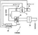
図1において、例えば自動車の内燃機関1が示されている。この場合、フレッシュ・エアが、空気系20を介して吸い込まれ且つ少なくとも1つのシリンダを含むエンジン15に供給される。ここで、フレッシュ・エアの流れ方向が矢印により示されている。エンジン15内の燃焼により発生した排気ガスは排気系25に供給される。空気系20内に圧縮機5が配置され、圧縮機5は、例えば排気ガス・ターボチャージャの圧縮機、または電動圧縮機、またはエンジン15のクランク軸により駆動される圧縮機であってもよい。図1において、流れ方向での圧縮機5手前の空気系20内の圧力がp1で示されている。また図1において、流れ方向での圧縮機5後方の空気系20内の圧力がp2で示されている。したがって、圧縮機5前後の圧力比はp2/p1である。即ち、p2はチャージ圧力であり、p1は吸気圧力である。流れ方向において圧縮機5後方の空気系20内に、空気質量流量測定装置10が配置され、空気質量流量測定装置10は、例えばホット・フィルム空気質量流量計として形成されていてもよい。ホット・フィルム空気質量流量計は、空気系20内のフレッシュ・エア質量ないしフレッシュ・エア質量流量を測定し、したがって圧縮機5内の質量流量を測定する。
FIG. 1 shows, for example, an internal combustion engine 1 of an automobile. In this case, fresh air is drawn into the
さらに、流れ方向において圧縮機5手前の空気系20内に第1の圧力センサ35が設けられ、第1の圧力センサ35は吸気圧力p1を測定する。さらにこの例においては、流れ方向において圧縮機5後方の空気系20内に第2の圧力センサ40が設けられ、第2の圧力センサ40はチャージ圧力p2を測定する。さらにエンジン制御装置30が設けられ、エンジン制御装置30は、空気質量流量測定装置(ホット・フィルム空気質量流量計)10、第1の圧力センサ35および第2の圧力センサ40と結合され、したがって、測定フレッシュ・エア質量、測定吸気圧力p1および測定チャージ圧力p2を受け取る。さらに、希望の圧縮機回転速度nvを設定するために、エンジン制御装置30は圧縮機を操作する。この場合、この操作は当業者に既知のように行われる。
Furthermore, a
図1においては、本発明を理解するために必要な内燃機関1の構成要素のみが示されている。
圧縮機サージングが発生したとき、空気系20内のフレッシュ・エア質量は、空気系20に対する特性周波数fDで振動する。この場合、特性周波数fDは、圧縮機サージングが意図的に発生される内燃機関1のテスト運転において決定することができる。このとき、特性周波数fDは、設定周波数としてエンジン制御装置30またはエンジン制御装置30に付属のメモリに記憶される。
FIG. 1 shows only the components of the internal combustion engine 1 necessary for understanding the present invention.
When compressor surging occurs, fresh air mass in the
静的圧縮機サージングにおいては2つの状態が存在する。第1の圧縮機サージング状態はフレッシュ・エア質量がより小さい振幅で振動することを特徴とするので、圧縮機サージングは全く聞こえないかまたは僅かに聞こえるにすぎない。第2の圧縮機サージング状態においては、空気質量流量はより大きい振幅で振動するので、圧縮機サージングはより強く聞こえる。即ち、両方の状態は、振動するフレッシュ・エア質量の振幅の大きさで区別される。第1の圧縮機サージング状態を介して、圧縮機5のサージ発生限界が求められ、ないし更新されるべきである。
There are two states in static compressor surging. Since the first compressor surging condition is characterized by the fresh air mass oscillating at a smaller amplitude, the compressor surging will be completely inaudible or only marginally audible. In the second compressor surging condition, the compressor surging sounds more intense because the air mass flow oscillates with a greater amplitude. That is, both states are distinguished by the magnitude of the amplitude of the oscillating fresh air mass. Via the first compressor surging state, the surge occurrence limit of the
離散フーリエ変換(DFT)により、特性周波数fDで振動するフレッシュ・エア質量の振幅が決定され且つこの結果として両方の状態が区別される。
信号列u(n)は、ホット・フィルム空気質量流量計10により測定されたフレッシュ・エア質量を示す。この場合、信号列u(n)は、エンジン制御装置30において走査周波数fSで走査される。ここで、走査周波数fSは、フレッシュ・エア質量の測定周波数とも呼ばれる。この場合、特性周波数fDを有する信号部分の振幅が求められる。ここで、fDは、上記のように、サージ発生限界を超えたときにフレッシュ・エア質量が振動する特性周波数である。
Discrete by Fourier transform (DFT), the amplitude of the fresh air mass that oscillates at a characteristic frequency f D both states are distinguished as a result are determined and.
The signal train u (n) indicates the fresh air mass measured by the hot film air
この場合、次式のように、特性周波数fDにおける信号列u(n)の振幅の二乗が得られる。
Amplitude2=a2+b2 (1)
ここで、aおよびbはそれぞれ、以下で与えられる。
In this case, as in the following equation, the square of the amplitude of the signal sequence u (n) in the characteristic frequency f D is obtained.
Amplitude 2 = a 2 + b 2 (1)
Where a and b are each given below.

k=fS/fD (4)
第1の圧縮機サージング状態は、特性周波数fDを有する信号部分の振幅が最小値Amplitudeminより大きく且つ最大値Amplitudemaxより小さいときに達成され、即ち、次の不等式が成立する。
The first compressor surging state is achieved when the amplitude of the signal part having the characteristic frequency f D is greater than the minimum value Amplitude min and less than the maximum value Amplitude max , ie the following inequality holds.
![]()
![]()
圧縮機5に固有のサージ発生限界はメーカーにより設定され、且つエンジン制御装置30内ないしエンジン制御装置30に付属のメモリ内に、圧力比p2/p1の、圧縮機5内の質量流量でもあるフレッシュ・エア質量流量に対する所定の線図として記憶される。圧縮機5内のこの質量流量は、流れ方向において圧縮機5手前の吸気圧力p1および温度により当業者に既知のように補正されてもよい。この所定の圧力比線図ないしサージ発生限界線図から、圧縮機5内の質量流量を介して、チャージ圧力p2に対する最大許容静的目標値が決定される。この場合、内燃機関1の運転において、例えば標高の関数として発生することがある最小可能吸気圧力p1が出発点となり、この場合、吸気圧力p1は、ほぼ周囲圧力に対応していてもよい。この場合、サージ発生限界を求めることがセクションごとに行われてもよい。このために、サージ発生限界は、フレッシュ・エア質量流量に関して、個々に求めることが可能な複数のセクションに分割される。所定のサージ発生限界線図が図3の圧縮機特性曲線群内に上記のように鎖線で記入されている。上記のDFTアルゴリズムを介して、第1の範囲内の特性周波数fDを有する信号部分の振幅、したがって第1の圧縮機サージング状態が検出された場合、学習アルゴリズムが適用される。この場合、サージ発生限界は、短時間の間、即ち、所定の時間の間、第1の所定の値Δ(p2/p1)1だけ低下され、これにより第2の圧縮機サージング状態の発生を阻止することができる。
The surge generation limit specific to the
所定の時間が経過した後に、サージ発生限界は再び上昇される。この場合、この所定の時間は、圧縮機5の操作によるチャージ圧力p2を制御するための時定数に基づき、および圧縮機5の慣性に基づいて、第2の範囲内の特性周波数fDを有する信号部分の振幅の上昇、したがってより激しく聞こえるサージ発生限界を回避することができるような、少なくともその程度の大きさに選択されている。この場合、チャージ圧力p2の制御は当業者に既知のように行われる。この所定の時間は、例えば内燃機関1のテスト運転により決定されても、また第2の範囲内の特性周波数fDを有する信号部分の振幅の上昇が十分に回避されるように適用されてもよい。第1の所定の値Δ(p2/p1)1は、同様に内燃機関1のテスト運転において、第2の圧縮機サージング状態を阻止するために、所定の時間の間、実際圧力比の、サージ発生限界からの十分な安全余裕が達成されるように適用されてもよい。第1の所定の値Δ(p2/p1)1および所定の時間は、同様にエンジン制御装置30内またはエンジン制御装置30に付属のメモリ内に記憶されていてもよい。
After a predetermined time has elapsed, the surge occurrence limit is raised again. In this case, the predetermined time based on the time constant for controlling the charge pressure p2 by the operation of the
サージ発生限界が所定の時間の間第1の所定の値Δ(p2/p1)1だけ実際に低減されている間に、エンジン制御装置30内ないしエンジン制御装置30に付属のメモリ内に記憶されている、それまでに求められた、ないし最初にメーカーにより設定された、圧縮機5内の質量流量に対するサージ発生限界が、第2の所定の値Δ(p2/p1)2だけ低減されることにより、新たなサージ発生限界が求められる。次に、所定の時間が経過した後に、第1の所定の値Δ(p2/p1)1だけ実際に低減されたサージ発生限界が、新たに求められたサージ発生限界に上昇される。新たに求められたサージ発生限界は、エンジン制御装置30内ないしエンジン制御装置30に付属のメモリ内に記憶され、且つそれまでに求められたサージ発生限界ないし最初にメーカーにより設定されたサージ発生限界曲線を置き換える。この場合、第2の所定の値Δ(p2/p1)2は、同様に内燃機関1のテスト運転において、新たに求められたサージ発生限界が、第1の圧縮機サージング状態に対してはもとより、第2の圧縮機サージング状態に対しても十分な安全余裕を保証するように適用されてもよく、これにより、新たに求められたサージ発生限界の使用においては、圧縮機サージングを懸念する必要はない。エンジン制御装置30内ないしそれに付属のメモリ内に、それぞれ新たに求められたサージ発生限界、または最初にメーカーにより設定されたサージ発生限界を新たに求められたサージ発生限界に低減させる、それぞれ新たに求められた補正値が記憶される。上記の学習過程は、フレッシュ・エア質量流量に対するサージ発生限界の全線図に対して行われても、または上記のようにセクションごとに行われてもよく、この場合、サージ発生限界はフレッシュ・エア質量流量の異なるセクションに対して別々に求められてもよい。この場合、第1の所定の値Δ(p2/p1)1および/または第2の所定の値Δ(p2/p1)2はフレッシュ・エア質量流量の全てのセクションに対して等しく選択され且つ例えば内燃機関1のテスト運転において典型的なセクションに対して適用されてもよい。代替態様として、第1の所定の値Δ(p2/p1)1および/または第2の所定の値Δ(p2/p1)2は、フレッシュ・エア質量流量の異なるセクションに対して異なるように適用され且つ設定されてもよい。所定の時間が経過した後に、新たに求められたサージ発生限界がフレッシュ・エア質量流量の全範囲に対して実際に使用されても、またはサージ発生限界が新たに求められ且つ実際のフレッシュ・エア質量流量が存在するセクションのみに使用されてもよい。ここで、上記のように、フレッシュ・エア質量流量は、圧縮機5内の質量流量に対応し、且つ圧縮機質量流量とも呼ばれ、また上記のように、流れ方向において圧縮機5手前の吸気圧力p1および/または温度の関数として補正されていてもよい。新たに求められたサージ発生限界ないし新たに求められた補正値の記憶は、上記のように、エンジン制御装置30内ないしエンジン制御装置30に付属のメモリ内に、例えば不揮発性として行われるので、対応のデータはエンジンが停止している間も記憶されたままである。場合により、セクションごとに決定された、新たに求められたサージ発生限界、ないし記憶されている、最初にメーカーにより設定されたサージ発生限界線図を補正するための、新たに求められた1つまたは複数の補正値に対して記憶されている値は、エンジン制御装置30の初期化において読み込まれる。エンジン制御装置30の初期化において、このように読み込まれた、新たに求められたサージ発生限界ないし新たに求められた1つまたは複数の補正値が第3の所定の値Δ(p2/p1)3だけ加算補正される。これにより、サージ発生限界が、徐々に再び、最初にメーカーにより設定された線図に接近することが達成される。この場合、第3の所定の値Δ(p2/p1)3は第2の所定の値より小さく選択されるので、一方で前に行われたサージ発生限界の低減の完全な補償が阻止され、他方でサージ発生限界の微調節を行うことができる。この場合、サージ発生限界は、第3の適用可能な値Δ(p2/p1)3が小さければ小さいほどそれだけより正確に設定可能である。他方で、このような微調節に対しては、第3の所定の値Δ(p2/p1)3が小さく選択されればされるほどそれだけ時間を要することになる。第3の所定の値Δ(p2/p1)3もまた、サージ発生限界のフレッシュ・エア質量流量に対する全線図に対して同じに選択されても、またはセクションごとに異なるように選択されてもよい。第3の所定の値Δ(p2/p1)3もまたエンジン制御30装置内またはエンジン制御装置30に付属のメモリ内に記憶されている。
While the surge occurrence limit is actually reduced by a first predetermined value Δ (p2 / p1) 1 for a predetermined time, the surge generation limit is stored in the
エンジン制御装置30は、それによって最初にメーカーにより設定されたサージ発生限界線図が超えられないときにのみ、第3の所定の値Δ(p2/p1)3による加算補正を行うように設計されていてもよい。
The
エンジン制御装置30の初期化は、新たなエンジン始動ごとに、したがって新たな走行サイクルごとに1回行われてもよい。ここで、以下に、本発明による方法のフローを図2の流れ図により詳細に説明する。この場合、上記のフローにおいては、サージ発生限界の完全な線図を求めるためだけでなく、サージ発生限界をセクションごとに求めるために使用されてもよく、この場合、後者のケースにおいては、フレッシュ・エア質量流量の個々のセクションに対してそれぞれ、このフローが実行されなければならない。プログラムは、例えばエンジン15の始動ごとにスタートされてもよい。プログラム・ランを、サージ発生限界に対する補正値を求める例で説明する。エンジン15の始動と同時に、エンジン制御装置30もまた初期化される。この場合、上記のように、それまでに求められた補正値がそのメモリから読み取られる。この場合、サージ発生限界は、最初にメーカーにより設定されたサージ発生限界線図である。したがって、補正値を求める過程がまだ行われていないので、読み込まれた、それまでに求められた補正値は、エンジンの始動時においては0に等しい。プログラム・ステップ100において、エンジン制御装置30は、それまでに求められた補正値が第3の所定の値Δ(p2/p1)3より小さいかどうかを検査する。これが肯定(y)の場合、プログラムはステップ110に分岐され、否定(n)の場合、ステップ105に分岐される。
The initialization of the
ステップ105において、それまでに求められた補正値から第3の所定の値Δ(p2/p1)3が差し引かれることにより、新たに求められた補正値が形成される。新たに求められた補正値を用いて、次に、メモリは、それまでに求められた補正値に対して上書きされる。それに続いて、エンジン制御装置30が、最初にメーカーにより設定されたサージ発生限界から、ステップ105において新たに求められた補正値を差し引くことにより、エンジン制御装置30は新たなサージ発生限界を設定する。それに続いてプログラムはステップ110に移行される。ステップ110において、エンジン制御装置30は、上記のように、離散フーリエ変換により、特性周波数fDを有する、ホット・フィルム空気質量流量計により測定されたフレッシュ・エア質量の信号部分の振幅を計算する。それに続いてプログラムはステップ115に移行される。
In
ステップ115において、エンジン制御装置30は、振幅が第1の範囲内にあるかどうかを検査する。これが肯定(y)の場合、プログラムはステップ120に分岐され、否定(n)の場合、ステップ135に分岐される。
In
ステップ135において、エンジン制御装置30は、現在の走行サイクルが終了したかどうか、即ちエンジン15が停止されたかどうかを検査する。これが肯定(y)の場合、プログラムは終了され、否定(n)の場合、プログラムはステップ110に戻される。
In
ステップ120において、エンジン制御装置30は、現在のサージ発生限界を第1の所定の値Δ(p2/p1)1だけ低減し且つタイマをスタートさせる。それに続いてプログラムはステップ125に移行される。ステップ125において、エンジン制御装置30は、場合によりプログラム点105において更新された、それまでに求められた補正値に対するメモリを読み取り、且つこの値に第2の所定の値Δ(p2/p1)2を加算する。このようにして、新たな補正値が求められ且つそれまでに求められた補正値に対するメモリ内に記憶される。したがって、新たなプログラム・ランに対しては、更新された補正値が使用される。それに続いてプログラムはステップ130に移行される。
In
ステップ130において、エンジン制御装置30が、最初にメーカーにより設定されたサージ発生限界から、ステップ125において新たに求められた補正値を差し引くことにより、エンジン制御装置30は新たなサージ発生限界を設定する。この場合、エンジン制御装置30による新たなサージ発生限界の設定は、ステップ120においてスタートされたタイマが所定の時間に到達したときに行われる。それに続いてプログラムは終了される。
In
所定の値の大きさの関係に対する有効な選択は、
Δ(p2/p1)1>Δ(p2/p1)2>Δ(p2/p1)3
のように行われてもよい。
A valid choice for a given value magnitude relationship is
Δ (p2 / p1) 1 > Δ (p2 / p1) 2 > Δ (p2 / p1) 3
It may be performed as follows.
サージ発生限界は、上記のように、エンジン15が作動している、内燃機関1の運転状態ごとに求められてもよい。エンジン15が作動しているかまたは停止しているかの検出は、例えば図1には示されていない回転速度センサにより決定されてもよく、回転速度センサは、エンジン15の回転速度を測定し且つエンジン制御装置30にその値を伝送する。このようにして、エンジン制御装置30は、エンジン15が始動されて上記のように図2のプログラムをスタートさせたかどうか、ないしエンジン15が停止され且つ走行サイクルが終了されてステップ135の問い合わせの後に図2のプログラムを離れたかどうかを特定することができる。
As described above, the surge occurrence limit may be obtained for each operating state of the internal combustion engine 1 in which the
1 内燃機関
5 圧縮機
10 空気質量流量測定装置(ホット・フィルム空気質量流量計)
15 エンジン
20 空気系
25 排気系
30 エンジン制御装置
35 圧力センサ(吸気圧力センサ)
40 圧力センサ(チャージ圧力センサ)
p1 吸気圧力
p2 チャージ圧力
u(n) 信号列(フレッシュ・エア質量)
DESCRIPTION OF SYMBOLS 1
15
40 pressure sensor (charge pressure sensor)
p1 Intake pressure p2 Charge pressure u (n) Signal train (fresh air mass)
Claims (10)
内燃機関(1)の少なくとも1つの運転状態において、圧縮機(5)のサージングが発生しているかどうかが検査されること、および
前記サージ発生限界が検査結果の関数として補正されること、
を特徴とする内燃機関の運転方法。 To prevent surging of the compressor (5), the pressure ratio across the compressor (5) is limited by the surge occurrence limit as a function of the mass flow in the compressor (5). In the method for operating the internal combustion engine (1) provided,
In at least one operating state of the internal combustion engine (1), it is checked whether surging of the compressor (5) has occurred, and the surge occurrence limit is corrected as a function of the test result;
An operation method for an internal combustion engine, comprising:
Applications Claiming Priority (1)
| Application Number | Priority Date | Filing Date | Title |
|---|---|---|---|
| DE10241892.6A DE10241892B4 (en) | 2002-09-10 | 2002-09-10 | Method for operating an internal combustion engine with a compressor |
Publications (1)
| Publication Number | Publication Date |
|---|---|
| JP2004100697A true JP2004100697A (en) | 2004-04-02 |
Family
ID=31502516
Family Applications (1)
| Application Number | Title | Priority Date | Filing Date |
|---|---|---|---|
| JP2003306800A Pending JP2004100697A (en) | 2002-09-10 | 2003-08-29 | Operating method for internal combustion engine equipped with compressor |
Country Status (3)
| Country | Link |
|---|---|
| US (1) | US6945234B2 (en) |
| JP (1) | JP2004100697A (en) |
| DE (1) | DE10241892B4 (en) |
Cited By (1)
| Publication number | Priority date | Publication date | Assignee | Title |
|---|---|---|---|---|
| JP2007092682A (en) * | 2005-09-29 | 2007-04-12 | Mazda Motor Corp | Supercharging device for engine |
Families Citing this family (14)
| Publication number | Priority date | Publication date | Assignee | Title |
|---|---|---|---|---|
| DE10237416A1 (en) * | 2002-08-16 | 2004-02-26 | Daimlerchrysler Ag | Operating method for turbocharger compressor which monitors frequency characteristic of air flow sensor signal to indicate presence of compressor pumping |
| US7007472B2 (en) * | 2004-02-10 | 2006-03-07 | Cummins, Inc. | System for limiting turbocharger rotational speed |
| DE102004035575A1 (en) * | 2004-07-22 | 2006-02-16 | Daimlerchrysler Ag | Method and device for controlling an internal combustion engine with a compressor, in particular an exhaust gas turbocharger |
| DE102004036553B3 (en) * | 2004-07-28 | 2006-01-05 | Bayerische Motoren Werke Ag | Reporting process for mean amplitude of air mass oscillations involves detecting air mass signal, reporting its gradient, producing two mean values and difference signal |
| US7167792B1 (en) | 2006-01-23 | 2007-01-23 | Ford Global Technologies, Llc | Method for stopping and starting an internal combustion engine having a variable event valvetrain |
| US7458346B2 (en) * | 2006-04-05 | 2008-12-02 | Ford Global Technologies, Llc | Method for controlling valves of an engine having a variable event valvetrain during an engine stop |
| US7562530B2 (en) * | 2006-04-05 | 2009-07-21 | Ford Global Technologies, Llc | Method for controlling an internal combustion engine having a variable event valvetrain |
| US7621126B2 (en) * | 2006-04-05 | 2009-11-24 | Ford Global Technoloigies, LLC | Method for controlling cylinder air charge for a turbo charged engine having variable event valve actuators |
| DE102008047802A1 (en) * | 2008-09-17 | 2010-04-01 | Knorr-Bremse Systeme für Nutzfahrzeuge GmbH | Fresh gas supply device for an internal combustion engine with turbocharger and method for its control |
| JP6186656B2 (en) * | 2013-06-27 | 2017-08-30 | 三菱日立パワーシステムズ株式会社 | Compressor control method, compressor deterioration determination method, and apparatus for executing these methods |
| CN108699966B (en) * | 2016-03-08 | 2021-08-24 | 三菱重工发动机和增压器株式会社 | Surge detection method and surge detection device for supercharger |
| DE102016220543B3 (en) * | 2016-10-20 | 2018-02-15 | Robert Bosch Gmbh | Method and device for detecting a compressor pumping of a turbocompressor of an internal combustion engine |
| DE102018201376A1 (en) | 2018-01-30 | 2019-08-01 | Robert Bosch Gmbh | Apparatus and method for controlling a compressor for an internal combustion engine |
| DE102020210642A1 (en) | 2020-08-21 | 2022-02-24 | Volkswagen Aktiengesellschaft | Method for modeling a compressor inlet temperature and/or a compressor outlet temperature of a compressor, a control device and a motor vehicle |
Family Cites Families (10)
| Publication number | Priority date | Publication date | Assignee | Title |
|---|---|---|---|---|
| CH407401A (en) | 1963-10-11 | 1966-02-15 | Bbc Brown Boveri & Cie | Method and device for controlling a thermal flow machine |
| DE3544821A1 (en) | 1985-12-18 | 1987-06-19 | Gutehoffnungshuette Man | METHOD FOR REGULATING TURBO COMPRESSORS TO AVOID THE PUMP |
| DE19719630C2 (en) * | 1997-05-09 | 1999-02-25 | Daimler Benz Ag | Method for regulating a supercharged internal combustion engine and device for carrying out the method |
| DE19816987A1 (en) | 1998-04-17 | 2000-02-03 | Rag Ag | Adapted pump limit of a centrifugal compressor |
| DE10007669B4 (en) | 2000-02-19 | 2005-09-15 | Daimlerchrysler Ag | Method for controlling a compressor, in particular a compressor in the intake tract of an internal combustion engine |
| DE10054843B4 (en) * | 2000-11-04 | 2006-09-14 | Daimlerchrysler Ag | Method for limiting the boost pressure |
| DE10122293A1 (en) * | 2001-05-08 | 2002-11-21 | Audi Ag | Method for regulating a boost pressure limitation of a turbocharger in an internal combustion engine as a function of the density of the ambient air |
| US6539714B1 (en) * | 2002-03-19 | 2003-04-01 | Cummins, Inc. | System for estimating turbocharger rotational speed |
| US6637205B1 (en) * | 2002-07-30 | 2003-10-28 | Honeywell International Inc. | Electric assist and variable geometry turbocharger |
| DE10237416A1 (en) | 2002-08-16 | 2004-02-26 | Daimlerchrysler Ag | Operating method for turbocharger compressor which monitors frequency characteristic of air flow sensor signal to indicate presence of compressor pumping |
-
2002
- 2002-09-10 DE DE10241892.6A patent/DE10241892B4/en not_active Expired - Lifetime
-
2003
- 2003-08-29 JP JP2003306800A patent/JP2004100697A/en active Pending
- 2003-09-10 US US10/658,264 patent/US6945234B2/en not_active Expired - Fee Related
Cited By (2)
| Publication number | Priority date | Publication date | Assignee | Title |
|---|---|---|---|---|
| JP2007092682A (en) * | 2005-09-29 | 2007-04-12 | Mazda Motor Corp | Supercharging device for engine |
| JP4595772B2 (en) * | 2005-09-29 | 2010-12-08 | マツダ株式会社 | Engine supercharger |
Also Published As
| Publication number | Publication date |
|---|---|
| US6945234B2 (en) | 2005-09-20 |
| DE10241892B4 (en) | 2021-12-23 |
| US20040115064A1 (en) | 2004-06-17 |
| DE10241892A1 (en) | 2004-03-11 |
Similar Documents
| Publication | Publication Date | Title |
|---|---|---|
| JP2004100697A (en) | Operating method for internal combustion engine equipped with compressor | |
| JP2581828B2 (en) | Air-fuel ratio control method for internal combustion engine and control device therefor | |
| KR101698355B1 (en) | Method and device for operating an internal combustion engine | |
| JP3281624B2 (en) | Knock detection method for internal combustion engine using ion current | |
| US20080264149A1 (en) | System and method for engine sound calibration | |
| JP2003307152A (en) | Method and device for failure diagnosis for map sensor of vehicle | |
| JP2001020785A (en) | Method and device for controlling internal combustion engine | |
| KR101981881B1 (en) | How to increase the pressure detection accuracy without using a sensor | |
| JPH10148152A (en) | Temperature estimating device for oxygen sensor in engine | |
| KR101454149B1 (en) | Method and device for controlling an internal combustion engine | |
| JP4395000B2 (en) | Engine control device | |
| JP4460077B2 (en) | Internal combustion engine control method and apparatus | |
| CN102278218B (en) | Detect the method and apparatus of cetane number | |
| KR20010059144A (en) | Method for boost pressure sensor fail safe of engine of vehicle | |
| CN114810390A (en) | Diesel engine, fuel injection quantity control method and device thereof and vehicle | |
| JP2003302312A (en) | Method for measuring moment of inertia of engine | |
| JPH0734924A (en) | Injection quantity controller of internal combustion engine | |
| JPS6153426A (en) | Control device for gas turbine engine | |
| KR100337331B1 (en) | Method for enhancing an engine idle stability of vehicle | |
| JPH0893572A (en) | Control method for egr quantity of gas engine and its device | |
| KR100291083B1 (en) | Method for controlling amount of fuel according to variable amount of opening in throttle valve | |
| KR100305815B1 (en) | Device and method for compensating air amount of vehicle | |
| JP4436997B2 (en) | Method and apparatus for monitoring vehicle and / or drive unit of each component assigned to vehicle | |
| KR19980039866U (en) | Start time control device of car | |
| JP3220844B2 (en) | Fuel injection timing control system for vehicle diesel engine |
Legal Events
| Date | Code | Title | Description |
|---|---|---|---|
| A621 | Written request for application examination |
Free format text: JAPANESE INTERMEDIATE CODE: A621 Effective date: 20060825 |
|
| A131 | Notification of reasons for refusal |
Free format text: JAPANESE INTERMEDIATE CODE: A131 Effective date: 20090508 |
|
| A601 | Written request for extension of time |
Free format text: JAPANESE INTERMEDIATE CODE: A601 Effective date: 20090807 |
|
| A602 | Written permission of extension of time |
Free format text: JAPANESE INTERMEDIATE CODE: A602 Effective date: 20090812 |
|
| A601 | Written request for extension of time |
Free format text: JAPANESE INTERMEDIATE CODE: A601 Effective date: 20090907 |
|
| A602 | Written permission of extension of time |
Free format text: JAPANESE INTERMEDIATE CODE: A602 Effective date: 20090910 |
|
| A601 | Written request for extension of time |
Free format text: JAPANESE INTERMEDIATE CODE: A601 Effective date: 20091007 |
|
| A602 | Written permission of extension of time |
Free format text: JAPANESE INTERMEDIATE CODE: A602 Effective date: 20091013 |
|
| A521 | Written amendment |
Free format text: JAPANESE INTERMEDIATE CODE: A523 Effective date: 20091019 |
|
| A02 | Decision of refusal |
Free format text: JAPANESE INTERMEDIATE CODE: A02 Effective date: 20091126 |