JP2004100548A - Exhaust gas processing device for internal combustion engine - Google Patents
Exhaust gas processing device for internal combustion engine Download PDFInfo
- Publication number
- JP2004100548A JP2004100548A JP2002262569A JP2002262569A JP2004100548A JP 2004100548 A JP2004100548 A JP 2004100548A JP 2002262569 A JP2002262569 A JP 2002262569A JP 2002262569 A JP2002262569 A JP 2002262569A JP 2004100548 A JP2004100548 A JP 2004100548A
- Authority
- JP
- Japan
- Prior art keywords
- passage
- secondary air
- exhaust
- air supply
- catalyst
- Prior art date
- Legal status (The legal status is an assumption and is not a legal conclusion. Google has not performed a legal analysis and makes no representation as to the accuracy of the status listed.)
- Pending
Links
Images


Classifications
-
- Y—GENERAL TAGGING OF NEW TECHNOLOGICAL DEVELOPMENTS; GENERAL TAGGING OF CROSS-SECTIONAL TECHNOLOGIES SPANNING OVER SEVERAL SECTIONS OF THE IPC; TECHNICAL SUBJECTS COVERED BY FORMER USPC CROSS-REFERENCE ART COLLECTIONS [XRACs] AND DIGESTS
- Y02—TECHNOLOGIES OR APPLICATIONS FOR MITIGATION OR ADAPTATION AGAINST CLIMATE CHANGE
- Y02T—CLIMATE CHANGE MITIGATION TECHNOLOGIES RELATED TO TRANSPORTATION
- Y02T10/00—Road transport of goods or passengers
- Y02T10/10—Internal combustion engine [ICE] based vehicles
- Y02T10/12—Improving ICE efficiencies
Abstract
Description
【0001】
【発明の属する技術分野】
本発明は、内燃機関からのHC等の有害物質の排出量を低減できる排気処理装置に関する。
【0002】
【従来の技術】
内燃機関の冷間始動時には燃焼室の温度が低く燃料の供給量も多いため、未燃物として大量のHC(炭化水素)が排出される。一般に、HCやCO等の有害物質は酸化触媒又は三元触媒を利用して浄化されるが、冷間始動時には触媒の温度が低くて触媒が活性化されていない。従って、始動時に一時的に大量に排出されるHCを触媒で効率よく浄化することは困難である。そこで、例えば特許文献1には、冷間始動後、触媒が所定の浄化性能を発揮するまでの間、HC吸着材を利用してHCの排出を抑える排気処理装置が提案されている。また、特許文献1には、吸気系に導入される一次空気とは別に排気通路の触媒よりも上流側に二次空気を供給し、排気ガスの二次燃焼の熱により触媒の暖機を促進する二次空気供給装置も開示されている。
【0003】
【特許文献1】
特開平7−42539号公報
【特許文献2】
特開平5−44447号公報
【特許文献3】
特開平11−148344号公報
【特許文献4】
特開平5−240037号公報
【0004】
【発明が解決しようとする課題】
上述した特許文献1の装置は、排気通路に設けられた二つの触媒の間にHC吸着材を配置し、温度上昇に伴ってHC吸着材から放出されるHCを下流側の触媒で処理している。このため、下流側の触媒が活性化するまでHC吸着材をHC放出温度よりも低温に維持する必要がある。その解決策として、特許文献1の装置では、二つの触媒を一体的に配置して上流側の触媒の熱で下流側の触媒の暖機を促進するとともに上流側の触媒からHC吸着材に導かれる排気の温度を下げている。しかしながら、このような機能を実現するためには、二つの触媒を二重管のように一体化する必要があって排気系の構成が複雑化し、その結果、排気系の耐久性や信頼性が劣化し、製造コストが上昇する等の不都合が生じる。また、上流側触媒からHC吸着材を経て下流側触媒に至る間に排気通路を少なくとも一周巻き回す必要があるため、排気通路の抵抗が増えて排気系の背圧が上昇し、内燃機関の性能が低下するおそれがある。
【0005】
そこで、本発明は、排気通路の構成を簡素化しつつHC等の有害物質の放出を抑えることができる内燃機関の排気処理装置を提供することを目的とする。
【0006】
【課題を解決するための手段】
本発明の第1の排気処理装置は、エアポンプから二次空気供給通路を介して排気通路中の触媒よりも上流側の位置に二次空気を供給可能な内燃機関の排気処理装置であって、前記排気通路から離されて前記二次空気供給通路に接続され、内燃機関からの排出物を保持可能な保持手段と、前記保持手段に向かう吸引力を前記二次空気供給通路に生じさせる吸引力付与手段と、を備えることにより、上述した課題を解決する(請求項1)。
【0007】
この排気処理装置によれば、HC等の有害物質が一時的に大量に排出される冷間始動時等において二次空気供給通路に吸引力を作用させて内燃機関からの排出物を保持手段に取り込むことにより、大気中へのHC等の放出を抑えることができる。保持手段に取り込んだ排出物は暖機完了後の触媒にこれを導き、あるいは吸気通路に戻すことにより事後的に処理すればよい。保持手段そのものに浄化機能を設けて排出物を処理することもできる。保持手段を排気通路上に設置せず、排気通路から離して二次空気供給通路と接続したので、排気通路上にHC吸着材等の保持手段を設ける場合のような複雑な構成の排気通路を形成する必要がない。従って、排気系に関する耐久性や信頼性が向上し、製造コストが低下し、排気通路の背圧が低下する等の利点が得られる。
【0008】
第1の排気処理装置は、排出物の吸引機能と二次空気の供給機能とを実現するものであるが、それらの機能は排気処理の都合に応じて適宜に使い分けてよい。一例として、前記触媒の状態が暖機完了前の第1段階にあるときは前記吸引力付与手段による吸引力を利用して前記保持手段に排出物を吸引し、前記触媒の状態が暖機完了前でかつ前記第1段階よりも暖機が進んだ第2段階にあるときは前記二次空気供給通路を介して前記排気通路に二次空気を供給してもよい(請求項2)。但し、HC等有害物質の放出が懸念される場合には第1段階に限らず、適宜に排出物を保持手段に吸引してよい。
【0009】
内燃機関の冷間始動の直後には、二次空気の供給により触媒が却って冷やされることがあり、そのような状態を第1段階として設定しておけば二次空気の供給を一旦保留して排出物を保持手段に吸引してHC等の有害物質の排出を防止し、その後、第2段階において二次空気を供給することにより未燃物と二次空気との混合による二次燃焼を促し、その燃焼熱で触媒の暖機を促進することができる。
【0010】
本発明の第1の排気処理装置においては、前記エアポンプを前記二次空気の供給時とは逆方向に回転させることにより当該エアポンプを前記吸引力付与手段として利用してもよい(請求項3)。この場合には、吸引力を生じさせるために新たにポンプ類を追加する必要がなく、排気処理装置の構成の簡素化やコストの削減をさらに図ることができる。
【0011】
また、本発明の第1の排気処理装置において、前記吸引力付与手段は、内燃機関の吸気通路に生じる負圧を前記保持手段に作用させて前記吸引力を生じさせてもよい(請求項4)。この場合にも、吸引力を生じさせるために新たにポンプ類を追加する必要がなく、排気処理装置の構成の簡素化やコストの削減をさらに図ることができる。負圧を導くために保持手段と吸気通路とを接続することから、保持手段にて保持している排出物を吸気通路に供給してEGRを実現することも可能となる。
【0012】
なお、吸気通路の負圧を利用して二次空気供給通路に吸引力を生じさせる場合には、前記排出物を前記保持手段に吸引する際に前記吸気通路と前記保持手段とを通じさせて前記吸気通路の負圧を前記保持手段に作用させてもよい(請求項5)。この場合には、排出物の吸引を必要とするときに吸気通路に現に発生している負圧を利用して効率よく排出物を吸引することができる。
【0013】
また、内燃機関の停止時に前記吸気通路と前記保持手段とを通じさせて前記吸気通路の負圧を前記保持手段に蓄え、前記排出物を前記保持手段に吸引する際に前記二次空気供給通路と前記保持手段とを通じさせて前記吸気通路に蓄えられた負圧を前記保持手段に作用させてもよい(請求項6)。この場合には、内燃機関の停止時に残存するエネルギーの少なくとも一部が負圧として保持手段に蓄えられて後の排出物の吸引に利用される。従って、内燃機関におけるエネルギーの利用効率が向上する。
【0014】
次に、本発明の第2の排気処理装置は、エアポンプから二次空気供給通路を介して排気通路中の触媒よりも上流側の位置に二次空気を供給可能な内燃機関の排気処理装置であって、前記排気通路から離されて前記二次空気供給通路に接続され、内燃機関からの排出物を保持可能な保持手段と、前記エアポンプの回転方向を、前記二次空気供給通路に対して前記二次空気を供給する正方向と、前記保持手段に向かう吸引力を前記二次空気供給通路に生じさせる逆方向との間で切替制御する制御手段と、を備えることにより、上述した課題を解決する(請求項7)。
【0015】
この第2の排気処理装置によれば、冷間始動時等にエアポンプを逆方向に回転させて二次空気供給通路に吸引力を作用させることにより、保持手段に排出物を取り込んで大気中へのHC等の有害物質の放出を抑えることができる。保持手段が保持する排出物は暖機完了後の触媒にこれを導き、あるいは吸気通路に戻すことにより、事後的に処理すればよい。保持手段そのものに浄化機能を設けて排出物を処理することもできる。保持手段を排気通路から離して二次空気供給通路と接続したので、第1の排気処理装置と同様に、排気系に関する耐久性や信頼性が向上し、製造コストが低下し、排気通路の背圧が低下する等の利点が得られる。さらに、吸引力を生じさせるために新たにポンプ類を追加する必要がなく、排気処理装置の構成の簡素化やコストの削減をさらに図ることができる。
【0016】
第2の排気処理装置においては、エアポンプの回転方向を切り替えることにより排出物の吸引機能と二次空気の供給機能とを選択的に実現するが、それらの機能は排気処理の都合に応じて適宜に使い分けてよい。一例として、前記制御手段は、前記触媒の状態が暖機完了前の第1段階にあるときは前記エアポンプを前記逆方向に回転させ、前記触媒の状態が暖機完了前でかつ前記第1段階よりも暖機が進んだ第2段階にあるときは前記エアポンプを前記正方向に回転させてもよい(請求項8)。但し、HC等有害物質の放出が懸念される場合には第1段階に限らず、適宜に排出物の吸引を行ってよい。
【0017】
また、第2の排気処理装置において、前記二次空気供給通路にはバイパス通路が設けられ、そのバイパス通路には前記保持手段と、前記保持手段よりも前記エアポンプに近い側に位置して当該バイパス通路を開閉する第1の弁手段と、前記保持手段よりも前記エアポンプから遠い側に位置して前記保持手段へ流入する方向の流れを許容し、前記保持手段から流出する方向の流れを阻止する第2の弁手段とが設けられ、前記保持手段には、当該保持手段と前記二次空気供給通路以外の所定位置とを連絡する連絡手段がさらに取り付けられてもよい(請求項9)。
【0018】
この場合には、二次空気供給通路に対するバイパス通路中の保持手段に排出物を取り込んで第1の弁手段を閉じることにより、保持手段に取り込まれた排出物を二次空気に含ませることなく保持手段に保持しておくことができる。保持手段に保持された排出物は連絡手段を介して所定位置に導き、適切に処理することができる。例えば、前記保持手段と内燃機関の吸気通路とを連絡するように連絡手段を設けてもよい(請求項10)。保持手段が浄化機能を有しているならば、連絡手段は例えば保持手段の内部を大気に開放するように設けられてもよい。
【0019】
さらに、本発明の第3の排気処理装置は、エアポンプから二次空気供給通路を介して排気通路中の触媒よりも上流側の位置に二次空気を供給可能な内燃機関の排気処理装置であって、前記排気通路から離され、前記二次空気供給通路と前記内燃機関の吸気通路とを結ぶ排気還流通路中に設けられ、内燃機関からの排出物を保持可能な保持手段と、前記排気還流通路の前記二次空気供給通路と前記保持手段との間に設けられて当該排気還流通路を開閉する第1開閉弁と、前記排気還流通路の前記保持手段と前記吸気通路との間に設けられて当該排気還流通路を開閉する第2開閉弁とを備えることにより、上述した課題を解決する(請求項11)。
【0020】
この第3の排気処理装置によれば、エアポンプを停止して第1開閉弁及び第2開閉弁を開くことにより、吸気通路の負圧を保持手段を介して二次空気供給通路に作用させ、二次空気供給通路を介して排出物を保持手段に取り込むことができる。従って、上述した第1及び第2の排気処理装置と同様に大気中へのHC等の有害物質の放出を抑えることができる。保持手段に取り込んだ排出物は暖機完了後の触媒にこれを導き、あるいは吸気通路に戻すことにより事後的に処理すればよい。保持手段そのものに浄化機能を設けて排出物を処理することもできる。第2開閉弁を開けば保持手段と吸気通路とが通じるので、保持手段の排出物を利用してEGRを実現することも可能である。保持手段を排気通路上に設置せず、排気通路から離して二次空気供給通路と接続したので、排気通路上にHC吸着材等の保持手段を設ける場合のような複雑な排気通路を形成する必要がない。従って、排気系に関する耐久性や信頼性が向上し、製造コストが低下し、排気通路の背圧が低下する等の利点が得られる。さらに、吸引力を生じさせるために新たにポンプ類を追加する必要がなく、排気処理装置の構成の簡素化やコストの削減をさらに図ることができる。また、第1開閉弁を閉じてエアポンプから二次空気供給通路に二次空気を送り込むことにより、保持手段への二次空気の流出を防ぎつつ二次空気を排気通路に供給することができる。
【0021】
本発明の第3の排気処理装置においては、前記触媒の状態が暖機完了前の第1段階にあるときは前記エアポンプを停止させるとともに前記第1開閉弁及び前記第2開閉弁を開いて前記吸気通路の負圧を前記保持手段及び前記二次空気供給通路に作用させ、前記触媒の状態が暖機完了前でかつ前記第1段階よりも暖機が進んだ第2段階にあるときは前記第1開閉弁及び第2開閉弁を閉じるとともに前記二次空気供給通路に二次空気が供給されるように前記エアポンプを回転させる制御手段を備えてもよい(請求項12)。あるいは、内燃機関の停止時に前記第1開閉弁を閉じ、前記第2開閉弁を開いて前記吸気通路の負圧を前記保持手段に取り込むとともに、その後に前記第2開閉弁を閉じて前記保持手段に負圧を蓄え、前記触媒の状態が暖機完了前の第1段階にあるときは前記エアポンプを停止させかつ前記第2開閉弁を閉じた状態で前記第1開閉弁を開いて前記保持手段に蓄えられた負圧を前記二次空気供給通路に作用させ、前記触媒の状態が暖機完了前でかつ前記第1段階よりも暖機が進んだ第2段階にあるときは前記第1開閉弁を閉じるとともに前記二次空気供給通路に二次空気が供給されるように前記エアポンプを回転させる制御手段を備えてもよい(請求項13)。
【0022】
前者の場合には、排出物の吸引を必要とするときに吸気通路に現に発生している負圧を利用して効率よく排出物を吸引することができる。後者の場合には、内燃機関の停止時に残存するエネルギーの少なくとも一部が負圧として保持手段に蓄えられて後の排出物の取り込みに利用される。従って、内燃機関におけるエネルギーの利用効率が向上する。但し、HC等有害物質の放出が懸念される場合には第1段階に限らず、適宜に排出物を吸引してよい。
【0023】
本発明において、保持手段は排気ガスを排出物としてそのまま保持してもよいし、排気ガス中に含まれる特定の物質を排出物として保持してもよい。後者の一例として、前記保持手段はHC吸着材を含んでもよい(請求項14)。保持手段としてHC吸着材を設ける場合にはその加熱手段を備えることが望ましい(請求項15)。加熱手段によりHC吸着材からのHCの放出を促すことができるからである。加熱手段としては前記触媒を利用することもできる(請求項16)。また、前記保持手段は排出物を蓄えるタンクを含んでもよい(請求項17)。この場合には内燃機関から放出される排出物を排気ガスのままタンク内に蓄えておくことができる。
【0024】
前記保持手段が保持する排出物は、二次空気に含めて前記排気通路に供給してもよいし(請求項18)、吸気通路に供給してもよい(請求項19)。前者の場合には二次空気供給装置から送られる二次空気に排出物が混ざるので、二次燃焼用の未燃物を補って触媒の暖機を促進させ、あるいは二次空気に含まれる酸素量を減らして排気通路内における過剰な酸化雰囲気の形成を抑え、NOx生成量を低減することができる。後者の場合には保持手段に保持された未燃物を吸気通路に戻して再燃焼させ、あるいは吸気中の酸素量を減らしてNOx生成量を低減させることができる。特に保持手段が排気ガスを保持する場合には、保持中に排気ガスが熱を放出して吸気通路に戻されるガスの温度が低下し、NOx生成量の低減効果が高まる。
【0025】
本発明の各排気処理装置において、二次空気供給通路は二次空気を排気通路に供給することをその目的の一つとして設けられており、少なくともその一部は排気通路に隣接している。従って、排気通路から二次空気供給通路には比較的容易に排気ガスを取り込むことができる。最も簡単には二次空気供給通路の排気通路へ二次空気を供給する開口部から排気ガスを吸い込むことができる。あるいは、二次空気を供給する開口部とは別の位置で排気通路と二次空気供給通路とを接続して排気ガスを二次空気供給通路に導くようにしてもよい。
【0026】
【発明の実施の形態】
(第1の実施形態)
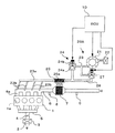
図1〜図3を参照して本発明の第1の実施形態を説明する。図1は本発明の第1の実施形態の排気処理装置とこれが取り付けられる内燃機関とを示している。内燃機関1は4つのシリンダ1aが一列に並べられた車両用の直列式4気筒ガソリンエンジンとして構成されている。周知のように、内燃機関1の吸気通路2には、スロットルバルブ4の開度に応じた空気(一次空気)がエアフィルタ3を介して吸入され、その空気はインテークマニホールド5を介して各シリンダ1aに取り込まれる。シリンダ1aからの排気ガスは排気通路6を経て触媒7に導かれて浄化された後、不図示の消音器を経て大気へ排出される。触媒7としては、HC、COを酸化する一方でNOxを還元する三元触媒やNOx吸蔵型触媒等が使用される。
【0027】
図1では省略したが、吸気通路2には、吸入空気量に対応した信号を出力するエアフローメータ、スロットルバルブ4の開度に対応した信号を出力するスロットル開度センサが設けられる。また、排気通路6の触媒7の前後には排気ガス中の酸素量に対応した信号を出力するO2センサ(空燃比センサでもよい。)8、9がそれぞれ設けられる。これらの他にも、内燃機関1の冷却水温度に対応した信号を出力する水温センサ、吸気温に対応した信号を出力する吸気温センサ、クランク軸の角度に対応した信号を出力するクランク角センサ等が内燃機関1に設けられる。各センサの出力信号はエンジンコントロールユニット(ECU)10に導かれる。ECU10はマイクロプロセッサ、及びその動作に必要なROM、RAM等の周辺回路を備えたコンピュータとして構成され、上述した各種のセンサの出力信号を参照して内燃機関1の燃料噴射量、燃料噴射時期、点火時期等を制御する。
【0028】
内燃機関1には排気処理装置20Aが取り付けられている。排気処理装置20Aは、空気供給源としての電動式のエアポンプ21と、そのエアポンプ21に吸い込まれる空気を濾過するフィルタ22と、エアポンプ21から吐出される空気を排気通路6に二次空気として導く二次空気供給通路23と、二次空気供給通路23を開閉するための第1のエアスイッチングバルブ(第1ASV)24とを備えている。エアポンプ21は回転方向を正逆方向に切替可能である。なお、二次空気供給通路23に対してエアを吐出する際の回転方向を正方向とし、正方向への回転を正転と表記する。
【0029】
二次空気供給通路23は、エアポンプ21から延びる主通路23aと、その主通路23aと各シリンダ1aの排気ポート6aとを結ぶ4本の枝通路23bとを備えている。第1ASV24は、エアポンプ21から主通路23aを経て枝通路23bに向かう方向の流れを許容し、その反対方向の流れを阻止するリードバルブ部24aと、電磁力を利用して主通路23aを開閉するソレノイドバルブ部24bとを備えている。
【0030】
排気処理装置20Aを排気ガスの捕集装置として機能させるため、二次空気供給通路23の主通路23aには排気ガスの保持手段としての貯蔵部25が設けられている。貯蔵部25は、第1ASV24よりも排気通路6に近い位置において主通路23aを部分的に拡大し、その拡大部分の内部にHC吸着材25aを収容して構成されている。貯蔵部25は、触媒7と貯蔵部25との間で熱交換を行うことができる程度に触媒7に隣接して配置されている。主通路23aの貯蔵部25よりもエアポンプ21に近い側には第1ASV24を迂回するバイパス通路26が接続されている。そのバイパス通路26には第2のエアスイッチングバルブ(第2ASV)27が設けられている。第2ASV27は電磁力を利用してバイパス通路26を開閉するソレノイドバルブである。
【0031】
エアポンプ21、第1ASV24のソレノイドバルブ部24b、及び第2ASV27の動作はECU10によって制御される。第1ASV24のソレノイドバルブ部24bを開いてエアポンプ21を正転させた場合には、二次空気供給通路23を介して排気通路6に二次空気が供給される。第1ASV24を閉じ、第2ASV27を開いてエアポンプ21を逆転させた場合には二次空気供給通路23に吸引力が作用し、排気ポート6aの排気ガスが枝通路23bから主通路23aに取り込まれる。HC吸着材25aが所定のHC放出温度以下であれば、二次空気供給通路23に取り込まれた排気ガス中のHCがHC吸着材25aに吸着される。HC吸着材25aの温度がHC放出温度以上になるとHC吸着材25aからはHCが放出される。なお、HC放出温度はHC吸着材25aに吸着されるHCの種類によって異なる。HC吸着材から放出されるHCは、エアポンプ21を正転させることによって二次空気とともに排気通路6に戻すことができる。その戻されたHCは排気通路6における二次燃焼又は触媒7の浄化作用を利用して処理することができる。
【0032】
エアポンプ21、第1ASV24、及び第2ASV27の動作は、二次空気の供給の必要性、及び排気ガスを貯蔵部25に取り込む必要性に応じて適宜に切り替えてよい。図2は、内燃機関1の冷間始動時にECU10が実行する排気処理装置20Aの好ましい動作制御の内容を示すタイムチャートである。
【0033】
図2の例では、内燃機関1のイグニッションスイッチがオンされてスタータモータが起動(ON)されると、エアポンプ21が逆転を開始し、第2ASV27が開かれる。第1ASV24は閉じた状態に維持される。ECU10は所定の条件に従って内燃機関1の始動の成否を監視しており、始動成功と判断するとRAMに記憶された始動フラグを始動状態に対応した値に変化させる。図2では始動状態をON、始動していない状態をOFFと表現して示しており、以下の説明では図2に倣って始動フラグの状態を表現する。始動フラグがONされた時期を基準として所定時間Aが経過するとエアポンプ21の回転方向が正方向に切り替えられ、第2ASV27が閉じられる。その後、所定時間Bが経過するまで第1ASV24、及び第2ASV27は閉じられる。所定時間Bが経過すると第1ASV24が開かれ、第2ASV27は閉じた状態に維持される。その後、所定時間Cが経過するとエアポンプ21が停止され、第1ASV24が閉じられる。
【0034】
以上の処理によれば、触媒7の暖機が完了する前の第1段階(所定時間Aの範囲)においてエアポンプ21が逆方向に駆動されて二次空気供給通路23に吸引力が作用し、排気ポート6aから排気ガスが吸い込まれてその排気ガス中のHCがHC吸着材25aに吸着される。この間、触媒7にも排気ガスは導かれており、その排気ガスに含まれる未燃物の二次燃焼により触媒7は徐々に加熱される。触媒7がある程度まで暖機されると二次空気供給通路23への排気ガスの吸引が停止され、その後、触媒7の暖機が完了するまでの第2段階(所定時間Bの経過時点から所定時間Cの経過時点まで)において排気通路6に二次空気が供給される。この間に、触媒7の熱によってHC吸着材25aが加熱されてHCが徐々に放出される。そして、HC吸着材25aから放出されたHCは貯蔵部25を通過する二次空気によって排気通路6に戻される。これにより排気通路6には二次空気供給通路23から酸素と未燃物とが供給される。その結果、内燃機関1から排出される未燃物及び二次空気供給通路23から戻される未燃物の二次燃焼が促進されて触媒7の暖機が早まる。
【0035】
上記の説明から明らかなように、所定時間Cは触媒7が所定の状態まで暖機されるために必要な時間として設定される。所定時間A,BについてはHC吸着材25aの吸着能力や触媒7の浄化能力を考慮して適宜に定めてよい。例えば、所定時間Aについては、HCの大気への放出量を所定の許容レベルに抑えられる程度まで触媒7が暖機されるために必要な時間、又は内燃機関1の始動時に大量のHCが一時的に排出される時間として設定してよい。あるいは、HC吸着材25aのHC吸着量がほぼ飽和するまでに要する時間として所定時間Aを設定してもよい。但し、二次空気の供給によって触媒7の暖機をなるべく早く完了させることを優先する限りにおいては、HCの放出量を許容レベルに抑えられる範囲において所定時間Aは短いほどよい。
【0036】
所定時間Bについては、エアポンプ21の回転方向を切り替える際に必要な遅延時間が所定時間Aとの間に生じるように定めればよい。例えば、エアポンプ21に対する回転方向の指示を切り替えてもエアポンプ21の羽根車(ベーン)の惰性により、実際の回転方向は直ぐには変化しないことがある。このような場合、エアポンプ21に対して回転方向の切り替えを指示してから、その指示に対応して実際に回転方向が切り替わるまでの時間以上の遅延時間を所定時間AとBとの間に設定することにより、エアポンプ21から実際に二次空気が送られてくるまで第1ASV24の開放を遅らせて排気ガスを含んだ空気の逆流を確実に防止することができる。
【0037】
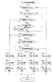
図3は図2のタイムチャートに則してエアポンプ21、第1ASV24及び第2ASV27を制御するためにECU10が実行する二次空気供給制御ルーチンを示すフローチャートである。この処理は内燃機関1のイグニッションスイッチがONされた後、所定の周期で繰り返し実行される。但し、その実行時期は、内燃機関1の始動後、触媒7の暖機が完了して二次空気の供給が不要と判断されるまでの一定期間に限ってもよい。
【0038】
図3のルーチンにおいて、ECU10はまずステップS11で二次空気供給条件が成立しているか否か判断する。二次空気供給条件は触媒7の暖機状態が所定のレベルまで達しているか否かを判断するための条件として設定されており、例えば冷却水の温度、吸気温度、触媒7の温度等、触媒7の暖機状態を判定するために使用可能な少なくとも一つのパラメータにより条件が設定される。触媒7の暖機が不足している場合に二次空気供給条件が成立していると判断され、その場合、ECU10はステップS12に進んで内燃機関1のスタータがONされているか否かを判断する。スタータがONされているときはステップS13へ進み、始動フラグがONか否か判断する。始動フラグがOFFのときはステップS17へ進んで第1ASV24を閉じ、ステップS18で第2ASV27を開け、ステップS19でエアポンプ21を逆転させる。この場合には貯蔵部25に向かって排気通路6から排気ガスが吸引される。
【0039】
一方、ステップS13で始動フラグがONされていれば前回のルーチン実行時にも始動フラグがONであったか否かを判断する。前回がONでないときはステップS15へ進んでタイマーを起動し、前回がONのときはステップS15をスキップする。ここで起動するタイマーは所定時間A,B,Cがそれぞれ経過したか否かを判断する基準となるものである。ステップS14又はステップS15の処理後はステップS16に進んで所定時間Aを経過しているか否か判断し、所定時間を超えていないときはステップS17以下に進む。所定時間Aを経過しているときはステップS20へ進んで所定時間Bが経過したか否か判断し、所定時間Bを経過していればステップS21へ進んで第1ASV24を閉じ、ステップS22で第2ASV27を閉じ、ステップS23でエアポンプ21を正転させる。
【0040】
ステップS20で所定時間Bが経過しているときはステップS24で所定時間Cが経過したか否か判断し、経過していないときはステップS25へ進んで第1ASV25を開け、ステップS26で第2ASV27を閉じ、ステップS27でエアポンプ21を正転させる。これにより二次空気が排気通路6に供給される。ステップS24で所定時間Cが経過していないときはステップS28へ進んで第1ASV24を閉じ、ステップS29で第2ASV27を閉じ、ステップS30でエアポンプ21を停止させる。ステップS11において二次空気供給条件が成立していないときもステップS28〜S30の処理を実行する。ステップS19,S23,S27,又はS30でエアポンプ21の動作を制御した後は今回のルーチンを終了して所定のメインルーチンに戻る。
【0041】
この実施形態では、ECU10がエアポンプ21を逆転させることによって吸引力付与手段を実現している。そして、ECU10がエアポンプの回転方向を切替制御する制御手段として機能し、触媒7が保持手段に対する加熱手段として機能する。制御手段はECU10とは別のコンピュータにより実現してもよい。触媒7に代え、電気的なヒータ等を加熱手段として利用してもよい。加熱手段は、HC吸着材25aを70〜80°C、最大でも200°C程度に加熱できればよい。
【0042】
(第2の実施形態)
図4〜図6を参照して本発明の第2の実施形態を説明する。なお、図4〜図6において図1〜図3との共通部分には同一の参照符号を付してある。
【0043】
図4の排気処理装置20Bにおいては、保持手段として、図1の貯蔵部25に代えてバイパス通路26の途中にタンク30が設けられている。従って、二次空気供給通路23に吸引された排気ガスはそのままタンク30に蓄えられる。タンク30は排気ガスの収容量に拘わりなく一定形状を保つ剛性の高い容器として構成されてもよいし、排気ガスの収容量に応じて形状が変化するフレキシブルな袋状の容器として構成されてもよい。第2ASV27はタンク30とエアポンプ21との間に設けられている。タンク30と排気ガスの取り込み部(枝通路23b)との間にはリードバルブ31が配置されている。リードバルブ31は枝通路23b側からのタンク30に向かう排気ガスの流れを許容し、その反対方向の排気ガスの流れを阻止する。
【0044】
タンク30はEGR通路32を介して吸気通路2と接続されている。EGR通路32にはこれを開閉するEGRバルブ33が設けられている。EGRバルブは第2ASV27等と同様にECU10からの指示に応じて開閉駆動されるソレノイドバルブである。EGR通路32と吸気通路2との接続位置は例えばインテークマニホールド5に設定される。
【0045】
以上の構成によれば、第1ASV24及びEGRバルブ33を閉じ、第2ASV27を開けてエアポンプ21を逆転させることにより、タンク30を介して二次空気供給通路23に吸引力を作用させて排気通路6の排気ガスをタンク30に吸い込むことができる。第2ASV27及びEGRバルブ33を閉じ、第1ASV24を開いてエアポンプ21を正転させたときは二次空気供給通路23を介して排気通路6に二次空気を供給することができる。さらに、第1ASV24及び第2ASV27を閉じた状態でEGRバルブ33を開いた場合には、吸気通路2の負圧をタンク30及び二次空気供給通路23に作用させて排気ガスを吸気通路2に取り込むEGRを実現することができる。なお、エアポンプ21を正転させた場合、リードバルブ31を介してタンク30にも二次空気が流れる可能性があるが、第2ASV27及びEGRバルブ33を閉じてタンク30からの圧力の流出を防いでいる限り、タンク30内の圧力が二次空気供給通路23の圧力とほぼ等しいか、又はそれ以上であればリードバルブ31が開くことはない。
【0046】
本実施形態においても、第1ASV24、第2ASV27及びEGRバルブ33の動作は二次空気の供給の必要性、排気ガスをタンク30に取り込む必要性、及びEGRを行う必要性に応じて適宜に切り替えてよい。図5は、内燃機関1の冷間始動時にECU10が実行する排気処理装置20Bの好ましい動作制御の内容を示すタイムチャートである。この例において、イグニッションスイッチ、スタータ、始動フラグ、エアポンプ21、第1ASV24及び第2ASV27のそれぞれの状態に関する相互関係は図2のそれと同じであり、詳細な説明は省略する。EGRバルブ33については、少なくとも所定時間Cが経過するまでは閉じた状態に維持され、その後の適当な時期に開かれる。
【0047】
図5のように各部の動作を切り替えた場合においては、触媒7の暖機が完了する前の第1段階(所定時間Aの範囲)においてエアポンプ21が逆方向に駆動されて二次空気供給通路23に吸引力が作用し、排気ポート6aからタンク30に排気ガスが吸い込まれる。この間、触媒7にも排気ガスは導かれており、その排気ガスに含まれる未燃物の二次燃焼により触媒7は徐々に加熱される。触媒7がある程度まで暖機されると二次空気供給通路23への排気ガスの吸引が停止され、その後、触媒7の暖機が完了するまでの第2段階(所定時間Bの経過時点から所定時間Cの経過時点まで)において排気通路6に二次空気が供給される。これにより、内燃機関1からの未燃物の二次燃焼が促進されて触媒7の暖機が早まる。
【0048】
また、二次空気の供給中にEGRバルブ33が閉じているので、タンク30内には排気ガスが保持される。その排気ガスは、後にEGRバルブ33が開かれることにより吸気通路2に戻される。これにより、吸気中の酸素量が減少してNOx生成量が減少する。タンク30に保持されている間に排気ガスが放熱するため、吸気通路2に戻される排気ガスの温度は排気ポート6aから直ぐに排気ガスを戻す場合と比較して低下する。従って、シリンダ1aにおける燃焼温度が低下し、NOx低減効果がさらに高まる。このようにタンク30はEGRクーラーとしても機能し得るものである。排気ガスの冷却効果を高めるため、タンク30に放熱フィンを設ける等、タンク30の内外の熱交換量を増加させる手段を設けてもよい。
【0049】
なお、図5のエアポンプ21、第1ASV24及び第2ASV27に関する動作制御は第1の実施形態と同様であるため、これを実現するためにECU10が実行すべき処理は図3の通りでよい。EGRバルブ33の制御については、図6に示すEGR制御ルーチンをECU10によって繰り返し実行すればよい。
【0050】
図6の処理は内燃機関1のイグニッションスイッチがONされた後、所定の周期で繰り返し実行される。このEGR制御ルーチンにおいて、ECU10はまずステップS31で二次空気の供給条件が成立しているか否か判断する。この処理は図3のステップS11と同じである。そして、供給条件が成立しているときはステップS34へ進み、EGRバルブ33を閉じてルーチンを終える。これにより、図5の所定時間Cが経過するまではEGRバルブ33が閉じた状態に確実に維持される。ステップS31で供給条件が成立していない場合にステップS32へ進み、EGR作動条件が成立しているか否か判断する。この条件は一般のEGR装置におけるEGRの適否の判別条件と同様に設定してよい。そして、EGR作動条件が成立していないときはステップS34に進む。
【0051】
一方、EGR作動条件が成立しているときはステップS33にてEGRバルブ33を開いてルーチンを終える。これにより、EGR作動条件が成立していればEGRバルブ33が開いて吸気通路2の負圧がタンク30及び二次空気供給通路23に作用し、タンク30に保持されていた排気ガスが吸気通路2に吸い込まれる。なお、EGRの実行中においては、排気通路6の排気ガスが二次空気供給通路23からリードバルブ31を介してタンク30内に逐次吸い込まれる。第1ASV24及び第2ASV27はいずれも閉じているので、タンク30内に外気が取り込まれてEGRの作用が損なわれるおそれはない。
【0052】
この実施形態では、ECU10がエアポンプ21を逆転させることによって吸引力付与手段が実現される。また、ECU10がエアポンプ21の回転方向を切替制御する制御手段として機能する。但し、制御手段はECU10とは別のコンピュータにより実現してもよい。さらに、第2ASV27が第1の弁手段に、リードバルブ31が第2の弁手段に、EGR通路32とEGRバルブ33とが連絡手段にそれぞれ相当する。保持手段として、タンク30に代えてHC吸着材25aを内蔵した貯蔵部25を設けてもよい。
【0053】
(第3の実施形態)
図7〜図10を参照して本発明の第3の実施形態を説明する。なお、図7〜図10において図1〜図6との共通部分には同一の参照符号を付してある。
【0054】
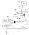
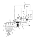
図7の排気処理装置20Cにおいては、図4に示した排気処理装置20Bのバイパス通路26に代え、二次空気供給通路23の主通路23aの第1ASV24よりも枝通路23b側の位置に導入通路34が接続され、その導入通路34の終端に第2ASV27を介してタンク30が接続されている。その他の構成は図4の排気処理装置20Bと同じである。
【0055】
本実施形態の構成では、エアポンプ21を逆転させたとしてもその吸引力はタンク30に作用せず、タンク30内に排気ガスを取り込むことはできない。その代わり、EGRバルブ33を開いて吸気通路2の負圧をタンク30に導入することにより、タンク30内に負圧を作用させ、さらに第1ASV24を閉じ、第2ASV27を開けてタンク30内の負圧を二次空気供給通路23に作用させることにより、排気通路6の排気ガスをタンク30内に吸い込むことができる。タンク30内に保持した排気ガスは、第1ASV24を閉じ、第2ASV27及びEGRバルブ33を開くことによりEGRとして吸気通路2に戻すことができる。二次空気を供給する際には第2ASV27を閉じ、第1ASV24を開いてエアポンプ21を正転させればよい。
【0056】
本実施形態においても、第1ASV24、第2ASV27及びEGRバルブ33の動作は二次空気の供給の必要性、排気ガスをタンク30に取り込む必要性、及びEGRを行う必要性に応じて適宜に切り替えてよい。図8は、内燃機関1の冷間始動時にECU10が実行する排気処理装置20Cの好ましい動作制御の内容を示すタイムチャートである。
【0057】
図8の例では、内燃機関1のイグニッションスイッチがオンされてスタータモータが起動(ON)されると第2ASV27が開かれ、所定の遅延時間dだけ遅れてEGRバルブ33が開かれる。エアポンプ21は停止状態に、第1ASV24は閉じた状態にそれぞれ維持される。遅延時間dを設けたのは、始動時の内燃機関1の回転数が上昇する途中でEGRバルブ33が開かれるとシリンダ内の燃焼が不安定になるため、内燃機関1の回転数が上昇して燃料が適度に安定したタイミングでEGRバルブ33を開くこととしたためである。始動フラグがONされた時期を基準として所定時間Aが経過すると第2ASV27及びEGRバルブ33がそれぞれ閉じられ、それらと引き替えに第1ASV24が開かれてエアポンプ21が正転を開始する。その後、所定時間Cが経過するとエアポンプ21が停止され、第1ASV24が閉じられる。エアポンプ21の回転開始後、少なくとも所定時間Cが経過するまでは第2ASV27及びEGRバルブ33が閉じた状態に維持される。そして、これらのバルブ27,33はエアポンプ21の停止後の適当な時期に開かれる。
【0058】
図8のように各部の動作を切り替えた場合においては、触媒7の暖機が完了する前の第1段階(所定時間Aの範囲)において、EGRバルブ33及び第2ASV27が開き、第1ASV24が閉じているので、吸気通路2の負圧がタンク30を介して二次空気供給通路23に作用し、排気ポート6aからタンク30に排気ガスが吸い込まれる。タンク30へ排気ガスを吸い込んでいる間、触媒7にも排気ガスは導かれており、その排気ガスに含まれる未燃物の二次燃焼により触媒7は徐々に加熱される。触媒7がある程度まで暖機されると二次空気供給通路23への排気ガスの吸引が停止され、その後、触媒7の暖機が完了するまでの第2段階(所定時間Aの経過時点から所定時間Cの経過時点まで)においてエアポンプ21が正方向に駆動されて排気通路6に二次空気が供給される。これにより、内燃機関1からの未燃物の二次燃焼が促進されて触媒7の暖機が早まる。
【0059】
二次空気の供給中、第2ASV27及びEGRバルブ33が閉じているのでタンク30内には排気ガスが保持され、タンク30からの放熱によりタンク30内の排気ガスの温度は徐々に低下する。そして、触媒7の暖機完了後の適当な時期に第2ASV27及びEGRバルブ33が開かれることにより、適度に冷まされた排気ガスがタンク30からEGR通路32を介して吸気通路2にEGRとして戻される。これによりNOx生成量が減少する。
【0060】
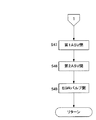
図9及び図10は図8のタイムチャートに則してエアポンプ21、第1ASV24、第2ASV27及びEGRバルブ33を制御するためにECU10が実行する二次空気供給制御ルーチンを示すフローチャートである。この処理は内燃機関1のイグニッションスイッチがONされた後、所定の周期で繰り返し実行される。
【0061】
図3に示した二次空気供給制御ルーチンとの比較において、図9及び図10の二次空気供給制御ルーチンは、ステップS20が省略され、ステップS19に代えてステップS41が設けられ、さらにステップS42〜S46(図9)、及びS47〜S49(図10)が追加された点が異なる。その他の部分は図3と同様である。以下では相違点を中心に説明する。
【0062】
まず、ステップS11で二次空気供給条件が成立している場合には、ステップS16で所定時間Aが経過したと判断されない限り、ステップS17へ進んで第1ASV24を閉じ、ステップS18で第2ASV27を開ける。この後、ステップS41に進んでエアポンプ21を停止し、ステップS42で遅延時間d中か否か判断し、遅延時間dであれば今回のルーチンを終了する。遅延時間dでなければステップS43にてEGRバルブ33を開けてルーチンを終える。これらの処理によれば、スタータON後、所定時間Aが経過するまでは吸気通路2の負圧が二次空気供給通路23側に作用して排気ガスがタンク30に吸引される。なお、遅延時間d中か否かの判断に関しては、例えば最初にステップS41の処理を実行した時点でタイマーを起動して遅延時間dまで計時が進んだか否かを判断することにより実行できる。
【0063】
一方、ステップS16で所定時間Aが経過しているときは続いてステップS24で所定時間Cが経過したか否かを判断する。そして、所定時間Cが経過していないときはステップS25で第1ASV24を開け、ステップS26で第2ASV27を閉じ、ステップS27でエアポンプ21を正転させる。さらに、ステップS44でEGRバルブ33を閉じてルーチンを終える。この場合はエアポンプ21から排気通路6に二次空気が送られ、第2ASV27及びEGRバルブ33が閉じているのでタンク30内に排気ガスが保持される。
【0064】
ステップS24で所定時間Cが経過していた場合にはステップS28で第1ASV24を閉じ、ステップS29で第2ASV22を閉じ、ステップS30でエアポンプ21を停止する。さらに、ステップS45でEGRバルブ33を閉じてルーチンを終える。
【0065】
ステップS11で供給条件が成立していないとき、つまり触媒7の暖機が完了しているときにはステップS46へ進み、EGR作動条件が成立しているか否か判断する。この条件は図6のステップS32のそれと同じでよい。そして、作動条件が成立していないときはステップS28以下へ処理を進める。一方、EGR作動条件が成立しているときは図10のステップS47へ進んで第1ASV24を閉じ、ステップS48で第2ASV27を開け、ステップS49でEGRバルブ33を開けてルーチンを終える。これにより、タンク30保持されていた排気ガスが吸気通路2に引き込まれてEGRが実現される。なお、EGRの実行中においては、排気通路6の排気ガスが二次空気供給通路23から第2ASV27を介してタンク30内に逐次吸い込まれる。第1ASV24は閉じているので、タンク30内に外気が取り込まれてEGRの作用が損なわれるおそれはない。
【0066】
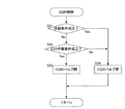
なお、排気処理装置20Cにおいては、タンク30に負圧を作用させる操作を内燃機関1の停止時に実行することもできる。例えば、図11に示すようにイグニッションスイッチのOFFに合わせて第2ASV27を閉じ、EGRバルブ33を所定時間開けてタンク30と吸気通路2とを一時的に通じさせ、その後に第2ASV27及びEGRバルブ33をいずれも閉じた状態に保持することによりタンク30に負圧を蓄えて次回の始動時等の吸引力として利用することができる。このように停止時に負圧を蓄える場合には、始動時に排気ガスをタンク30に吸い込む際にEGRバルブ33は閉じたままでよい。
【0067】
図12は、図11に従ってタンク30に負圧を取り込む場合にECU10が実行すべき負圧取り込み制御ルーチンの一例を示すフローチャートである。この負圧取り込み制御ルーチンは、例えばイグニッションスイッチのOFFをトリガとして所定の周期で繰り返し実行すればよい。最初のステップS51では第2ASV27を閉じ、次のステップS52でEGRバルブ33を開け、続くステップS53でEGRバルブ33を開けている時間を計時するためのタイマーを起動する。なお、既にタイマーが起動しているときはリセットせず、計時を継続させる。次のステップS54では始動フラグのOFFへの変更を禁止し、ステップS55でEGRバルブ33の開放時間が所定時間を経過したか否かをタイマーの計時時間から判断する。そして、所定時間が経過していなければルーチンを終え、所定時間が経過していればステップS56でEGRバルブ33を閉じ、ステップS57で始動フラグのOFFへの変更禁止を解除してルーチンを終える。
【0068】
この実施形態では、ECU10が排気ガスのタンク30への吸引時、又は内燃機関1の停止時にEGRバルブ33及び第2ASV27を開くことによって吸引力付与手段が実現される。また、導入通路34及びEGR通路32によって排気還流通路が構成され、第2ASV27が第1開閉弁に、EGRバルブ33が第2開閉弁にそれぞれ相当する。保持手段として、タンク30に代えてHC吸着材25aを内蔵した貯蔵部25を設けてもよい。
【0069】
本発明は以上の実施形態に限定されず、様々な形態にて実施してよい。上記の各実施形態では二次空気供給通路23の枝通路23bから排気ガスを取り込むようにしたが、別の位置から排気ガスを取り込んでもよい。一例として、図13に示すように排気通路6と二次空気供給通路23とを結ぶ吸入通路35を枝通路23bとは別に設け、その吸入通路35と二次空気供給通路23との接続位置に設けた切換弁36により、エアポンプ21及び貯蔵部25を二次空気供給時には枝通路23b側に、排気ガスの取込み時には吸入通路35側に択一的に接続してもよい。この場合には二次空気を供給する位置と、排気ガスを取り込む位置とをそれらの目的に応じた最適な位置に設定できる利点がある。二次空気についてはなるべく排気ガスの温度が高い位置に供給することが望ましいために枝通路23bはシリンダ1aになるべく近い位置に開口させ、吸入通路35に関しては排気ガスの流速が低いほど効率よく排気ガスを取り込めることから枝通路23bよりも下流側でかつ触媒7よりも上流側で排気通路6に接続する。
【0070】
図14に示すように、吸入通路35を触媒7よりも下流側で排気通路6と接続してもよい。この場合には触媒7を通過した排気ガスを貯蔵部25に取り込むので始動時期に触媒7により大量の排気ガスを導くことができて二次燃焼による暖機促進効果が高まる。また、二次空気供給通路23へ排気ガスを取り込む流量を増加させることにより、触媒7で処理できない排気ガスの全部又は大半を貯蔵部25に取り込むこともでき、大気中への有害物質の放出防止効果をさらに高めることができる。
【0071】
なお、図13及び図14に示した吸入通路35及び切換弁36は上述した第2又は第3の実施形態においてもこれを適用することが可能である。図3又は図9に示したフローチャートにおけるタイマーの起動(ステップS15)は、イグニッションON、又はスタータONに対応付けて実行してもよい。排気ガスを取り込む期間及び二次空気を供給する期間は、経過時間によって定める例に限らず、始動時からの積算吸入空気量、排気ガスの流量、二次空気の流量等の触媒7の暖機の進行に関連性を有すると考えられる各種の物理量と関連付けて定めてよい。
【0072】
【発明の効果】
以上に説明したように、本発明の排気処理装置によれば、HC等の有害物質が一時的に大量に排出される冷間始動時等において二次空気供給通路に吸引力を作用させて内燃機関からの排出物を保持手段に取り込むことにより、大気中へのHC等の有害物質の放出を抑えることができる。しかも、保持手段を排気通路上に設置せず、排気通路から離して二次空気供給通路と接続したので、排気通路上にHC吸着材等の保持手段を設ける場合のような複雑な構成の排気通路を形成する必要がない。従って、排気通路の構成を簡素化して排気系に関する耐久性や信頼性を向上させ、製造コストを低下させ、排気通路の背圧を低下させる等の優れた効果が得られる。
【図面の簡単な説明】
【図1】本発明の第1の実施形態に係る排気処理装置の概略構成を示す図。
【図2】図1の内燃機関を冷間始動させたときの排気処理装置の各部の状態の相関関係を示すタイムチャート。
【図3】図2のタイムチャートに則して動作を制御するためにECUが実行する二次空気供給制御ルーチンのフローチャート。
【図4】本発明の第2の実施形態に係る排気処理装置の概略構成を示す図。
【図5】図4の内燃機関を冷間始動させたときの排気処理装置の各部の状態の相関関係を示すタイムチャート。
【図6】図5のタイムチャートに則してEGRバルブの動作を制御するためにECUが実行するEGR制御ルーチンのフローチャート。
【図7】本発明の第3の実施形態に係る排気処理装置の概略構成を示す図。
【図8】図7の内燃機関を冷間始動させたときの排気処理装置の各部の状態の相関関係を示すタイムチャート。
【図9】図8のタイムチャートに則して動作を制御するためにECUが実行する二次空気供給制御ルーチンのフローチャート。
【図10】図9に続くフローチャート。
【図11】図8の実施形態の変形例を示すタイムチャート。
【図12】図8のタイムチャートに則して動作を制御するためにECUが実行する負圧取込み制御ルーチンのフローチャート。
【図13】排気ガスの取り込み位置を変更した変形例を図1に対応して示す図。
【図14】図13のさらなる変形例を示す図。
【符号の説明】
1 内燃機関
2 吸気通路
6 排気通路
10 エンジンコントロールユニット
20A,20B,20C 排気処理装置
21 エアポンプ
23 二次空気供給通路
23a 主通路
23b 枝通路
24 第1のエアスイッチングバルブ
24a リードバルブ部
24b ソレノイドバルブ部
25 貯蔵部
25a HC吸着材
26 バイパス通路
27 第2のエアスイッチングバルブ
30 タンク
31 リードバルブ
32 EGR通路
33 EGRバルブ
34 接続通路[0001]
TECHNICAL FIELD OF THE INVENTION
The present invention relates to an exhaust treatment device capable of reducing the emission of harmful substances such as HC from an internal combustion engine.
[0002]
[Prior art]
During a cold start of the internal combustion engine, a large amount of HC (hydrocarbon) is discharged as unburned matter because the temperature of the combustion chamber is low and the supply amount of fuel is large. Generally, harmful substances such as HC and CO are purified using an oxidation catalyst or a three-way catalyst. However, at the time of cold start, the temperature of the catalyst is low and the catalyst is not activated. Therefore, it is difficult to efficiently purify a large amount of HC that is temporarily discharged at the time of starting with a catalyst. Therefore, for example,
[0003]
[Patent Document 1]
JP-A-7-42539
[Patent Document 2]
JP-A-5-44447
[Patent Document 3]
JP-A-11-148344
[Patent Document 4]
JP-A-5-240037
[0004]
[Problems to be solved by the invention]
In the device of
[0005]
Therefore, an object of the present invention is to provide an exhaust treatment device for an internal combustion engine that can suppress emission of harmful substances such as HC while simplifying the configuration of an exhaust passage.
[0006]
[Means for Solving the Problems]
A first exhaust treatment device of the present invention is an exhaust treatment device for an internal combustion engine capable of supplying secondary air from an air pump to a position upstream of a catalyst in an exhaust passage via a secondary air supply passage, A holding means connected to the secondary air supply passage apart from the exhaust passage and capable of holding the exhaust from the internal combustion engine; and a suction force for generating a suction force toward the holding means in the secondary air supply passage. The above-mentioned subject is solved by providing an application means (claim 1).
[0007]
According to this exhaust treatment device, at the time of cold start or the like, in which a large amount of harmful substances such as HC are temporarily discharged, a suction force is applied to the secondary air supply passage, and the discharge from the internal combustion engine is transferred to the holding means. By taking in, release of HC and the like into the atmosphere can be suppressed. The discharged matter taken into the holding means may be guided to the catalyst after the warm-up is completed, or may be returned to the intake passage for post-treatment. It is also possible to treat the effluent by providing a purifying function in the holding means itself. Since the holding means is not installed on the exhaust passage, but is connected to the secondary air supply passage apart from the exhaust passage, an exhaust passage having a complicated structure such as a case where a holding means such as an HC adsorbent is provided on the exhaust passage is used. No need to form. Therefore, advantages such as improved durability and reliability of the exhaust system, reduced manufacturing cost, and reduced back pressure in the exhaust passage are obtained.
[0008]
The first exhaust processing device realizes a function of sucking the discharged material and a function of supplying the secondary air, and these functions may be appropriately used depending on the convenience of the exhaust processing. As an example, when the state of the catalyst is at the first stage before the completion of the warm-up, the discharged material is sucked into the holding means using the suction force of the suction force applying means, and the state of the catalyst is the state of the completion of the warm-up. Before and in the second stage where the warming-up has advanced from the first stage, the secondary air may be supplied to the exhaust passage via the secondary air supply passage (claim 2). However, when there is a concern about release of harmful substances such as HC, the discharge is not limited to the first stage, and the discharged matter may be appropriately sucked into the holding means.
[0009]
Immediately after the cold start of the internal combustion engine, the catalyst may be cooled by the supply of the secondary air, and if such a state is set as the first stage, the supply of the secondary air is temporarily suspended. The exhaust is sucked into the holding means to prevent the emission of harmful substances such as HC, and then the secondary air is supplied in the second stage to promote the secondary combustion by mixing the unburned matter and the secondary air. The warming of the catalyst can be promoted by the combustion heat.
[0010]
In the first exhaust treatment device of the present invention, the air pump may be used as the suction force applying means by rotating the air pump in a direction opposite to a direction in which the secondary air is supplied (claim 3). . In this case, it is not necessary to newly add pumps in order to generate a suction force, and it is possible to further simplify the configuration of the exhaust treatment device and further reduce the cost.
[0011]
In the first exhaust treatment apparatus of the present invention, the suction force applying means may generate the suction force by applying a negative pressure generated in an intake passage of an internal combustion engine to the holding means (Claim 4). ). Also in this case, it is not necessary to newly add pumps to generate a suction force, so that the configuration of the exhaust treatment device can be simplified and the cost can be further reduced. Since the holding means and the intake passage are connected to guide the negative pressure, the EGR can be realized by supplying the waste held by the holding means to the intake passage.
[0012]
In the case where a suction force is generated in the secondary air supply passage by using the negative pressure of the intake passage, when the discharge is sucked into the holding unit, the discharge is caused to pass through the intake passage and the holding unit. The negative pressure of the intake passage may act on the holding means (claim 5). In this case, the waste can be efficiently sucked by utilizing the negative pressure actually generated in the intake passage when the discharge needs to be sucked.
[0013]
Further, when the internal combustion engine is stopped, the negative pressure of the intake passage is stored in the holding unit through the intake passage and the holding unit, and the secondary air supply passage is used when the discharge is sucked into the holding unit. The negative pressure accumulated in the intake passage through the holding means may act on the holding means (claim 6). In this case, at least a part of the energy remaining when the internal combustion engine is stopped is stored in the holding means as a negative pressure, and is used for suctioning the exhaust afterward. Therefore, the energy use efficiency of the internal combustion engine is improved.
[0014]
Next, a second exhaust treatment device of the present invention is an exhaust treatment device for an internal combustion engine capable of supplying secondary air from an air pump to a position upstream of a catalyst in an exhaust passage via a secondary air supply passage. Holding means that is separated from the exhaust passage and is connected to the secondary air supply passage, and that can hold exhaust from the internal combustion engine, and rotates the air pump in the rotation direction with respect to the secondary air supply passage. By providing control means for switching control between a forward direction in which the secondary air is supplied and a reverse direction in which a suction force directed to the holding means is generated in the secondary air supply passage, the above-described problem is solved. Solved (claim 7).
[0015]
According to the second exhaust treatment apparatus, at the time of a cold start or the like, the air pump is rotated in the reverse direction to apply a suction force to the secondary air supply passage, thereby taking in the discharged matter into the holding means and putting it into the atmosphere. Emission of harmful substances such as HC can be suppressed. The discharged matter held by the holding means may be treated afterward by guiding the discharged matter to the catalyst after the warm-up is completed, or by returning it to the intake passage. It is also possible to treat the effluent by providing a purifying function in the holding means itself. Since the holding means is separated from the exhaust passage and connected to the secondary air supply passage, the durability and reliability of the exhaust system are improved, the manufacturing cost is reduced, and the height of the exhaust passage is reduced. Advantages such as a decrease in pressure are obtained. Further, it is not necessary to newly add pumps to generate a suction force, so that it is possible to further simplify the configuration of the exhaust treatment device and reduce costs.
[0016]
In the second exhaust processing device, the function of sucking the discharged material and the function of supplying the secondary air are selectively realized by switching the rotation direction of the air pump, and these functions are appropriately performed according to the convenience of the exhaust processing. You may use it properly. As an example, when the state of the catalyst is at the first stage before the completion of warm-up, the control unit rotates the air pump in the reverse direction, and when the state of the catalyst is before the completion of warm-up and the first stage The air pump may be rotated in the forward direction when the warming-up is in the second stage, which is more advanced (claim 8). However, when there is a concern about the release of harmful substances such as HC, the discharge is not limited to the first stage, and the discharge may be appropriately suctioned.
[0017]
Further, in the second exhaust treatment device, a bypass passage is provided in the secondary air supply passage, and the bypass passage is provided with the holding means and the bypass located closer to the air pump than the holding means. A first valve means for opening and closing the passage, and a flow path in the direction of flowing into the holding means, which is located farther from the air pump than the holding means, and preventing the flow in the direction of flowing out of the holding means; A second valve means may be provided, and the holding means may be further provided with a communication means for communicating the holding means with a predetermined position other than the secondary air supply passage (claim 9).
[0018]
In this case, the discharge is taken into the holding means in the bypass passage for the secondary air supply passage and the first valve means is closed, so that the discharge taken into the holding means is not included in the secondary air. It can be held by holding means. The discharged matter held by the holding means is guided to a predetermined position via the communication means, and can be appropriately processed. For example, a communication means may be provided so as to connect the holding means to an intake passage of the internal combustion engine (claim 10). If the holding means has a purifying function, the communication means may be provided to open the inside of the holding means to the atmosphere, for example.
[0019]
Further, a third exhaust treatment device of the present invention is an exhaust treatment device for an internal combustion engine capable of supplying secondary air from an air pump to a position upstream of a catalyst in an exhaust passage via a secondary air supply passage. Holding means that is provided in an exhaust gas recirculation passage that is separated from the exhaust gas passage and connects the secondary air supply passage and the intake air passage of the internal combustion engine, and that can retain exhaust from the internal combustion engine; A first on-off valve provided between the secondary air supply passage of the passage and the holding means for opening and closing the exhaust gas recirculation passage, and provided between the holding means and the intake passage of the exhaust gas recirculation passage; By providing a second on-off valve for opening and closing the exhaust gas recirculation passage, the above-described problem is solved (claim 11).
[0020]
According to the third exhaust treatment device, the air pump is stopped and the first on-off valve and the second on-off valve are opened, so that the negative pressure of the intake passage acts on the secondary air supply passage via the holding means, The discharge can be taken into the holding means via the secondary air supply passage. Therefore, release of harmful substances such as HC into the atmosphere can be suppressed as in the first and second exhaust treatment devices described above. The discharged matter taken into the holding means may be guided to the catalyst after the warm-up is completed, or may be returned to the intake passage for post-treatment. It is also possible to treat the effluent by providing a purifying function in the holding means itself. When the second on-off valve is opened, the holding means and the intake passage communicate with each other, so that EGR can be realized by using the discharge of the holding means. Since the holding means is not installed on the exhaust passage but is connected to the secondary air supply passage apart from the exhaust passage, a complicated exhaust passage is formed as in the case where a holding means such as an HC adsorbent is provided on the exhaust passage. No need. Therefore, advantages such as improved durability and reliability of the exhaust system, reduced manufacturing cost, and reduced back pressure in the exhaust passage are obtained. Further, it is not necessary to newly add pumps to generate a suction force, so that it is possible to further simplify the configuration of the exhaust treatment device and reduce costs. Further, by closing the first on-off valve and feeding the secondary air from the air pump into the secondary air supply passage, the secondary air can be supplied to the exhaust passage while preventing the secondary air from flowing out to the holding means.
[0021]
In the third exhaust treatment device of the present invention, when the state of the catalyst is at the first stage before the completion of warm-up, the air pump is stopped, and the first and second on-off valves and the second on-off valve are opened to open the catalyst. When the negative pressure of the intake passage is applied to the holding means and the secondary air supply passage, and the state of the catalyst is in a second stage before the completion of the warm-up and in a second stage where the warm-up is advanced from the first stage, Control means for closing the first on-off valve and the second on-off valve and rotating the air pump so that secondary air is supplied to the secondary air supply passage may be provided (claim 12). Alternatively, when the internal combustion engine is stopped, the first opening / closing valve is closed, the second opening / closing valve is opened, and the negative pressure of the intake passage is taken into the holding means, and then the second opening / closing valve is closed and the holding means is closed. When the state of the catalyst is at the first stage before the completion of warming-up, the air pump is stopped and the first on-off valve is opened with the second on-off valve closed, and the holding means is opened. The negative pressure stored in the second air supply passage is applied to the secondary air supply passage, and when the state of the catalyst is in a second stage in which the warm-up is more advanced than the first stage before the warm-up is completed, the first opening / closing is performed. Control means for closing the valve and rotating the air pump so that the secondary air is supplied to the secondary air supply passage may be provided (claim 13).
[0022]
In the former case, the waste can be efficiently sucked by utilizing the negative pressure actually generated in the intake passage when the exhaust needs to be sucked. In the latter case, at least a part of the energy remaining when the internal combustion engine is stopped is stored in the holding means as a negative pressure, and is used for taking in the emission later. Therefore, the energy use efficiency of the internal combustion engine is improved. However, if there is a concern about release of harmful substances such as HC, the discharge is not limited to the first stage, and the discharged matter may be appropriately sucked.
[0023]
In the present invention, the holding means may hold the exhaust gas as an emission as it is, or may hold a specific substance contained in the exhaust gas as an emission. As an example of the latter, the holding means may include an HC adsorbent (claim 14). When the HC adsorbent is provided as the holding means, it is desirable to provide the heating means (claim 15). This is because the heating means can promote the release of HC from the HC adsorbent. The catalyst may be used as the heating means (claim 16). Further, the holding means may include a tank for storing the discharge (claim 17). In this case, the exhaust discharged from the internal combustion engine can be stored in the tank as the exhaust gas.
[0024]
The discharged matter held by the holding means may be supplied to the exhaust passage while being included in secondary air (claim 18) or may be supplied to the intake passage (claim 19). In the former case, the exhaust gas is mixed with the secondary air sent from the secondary air supply device, so the unburned material for secondary combustion is supplemented to promote the warm-up of the catalyst, or the oxygen contained in the secondary air is By reducing the amount, formation of an excessive oxidizing atmosphere in the exhaust passage can be suppressed, and the NOx generation amount can be reduced. In the latter case, the unburned matter held by the holding means can be returned to the intake passage and recombusted, or the amount of oxygen in the intake air can be reduced to reduce the NOx generation amount. In particular, when the holding means holds the exhaust gas, the temperature of the gas returned to the intake passage by the exhaust gas releasing heat during the holding decreases, and the effect of reducing the NOx generation amount increases.
[0025]
In each of the exhaust treatment devices of the present invention, the secondary air supply passage is provided for the purpose of supplying secondary air to the exhaust passage, and at least a part thereof is adjacent to the exhaust passage. Therefore, the exhaust gas can be relatively easily taken into the secondary air supply passage from the exhaust passage. In the simplest case, the exhaust gas can be sucked from the opening for supplying the secondary air to the exhaust passage of the secondary air supply passage. Alternatively, the exhaust gas may be guided to the secondary air supply passage by connecting the exhaust passage and the secondary air supply passage at a position different from the opening for supplying the secondary air.
[0026]
BEST MODE FOR CARRYING OUT THE INVENTION
(1st Embodiment)
A first embodiment of the present invention will be described with reference to FIGS. FIG. 1 shows an exhaust treatment device according to a first embodiment of the present invention and an internal combustion engine to which the exhaust treatment device is attached. The
[0027]
Although not shown in FIG. 1, the
[0028]
The
[0029]
The secondary
[0030]
In order for the
[0031]
The operations of the
[0032]
The operations of the
[0033]
In the example of FIG. 2, when the ignition switch of the
[0034]
According to the above processing, the
[0035]
As is clear from the above description, the predetermined time C is set as a time required for the
[0036]
The predetermined time B may be determined so that a delay time required when switching the rotation direction of the
[0037]
FIG. 3 is a flowchart showing a secondary air supply control routine executed by the
[0038]
In the routine of FIG. 3, the
[0039]
On the other hand, if the start flag is ON in step S13, it is determined whether the start flag was ON at the time of the previous execution of the routine. If the previous time is not ON, the process proceeds to step S15 to start the timer, and if the previous time is ON, step S15 is skipped. The timer started here is a criterion for judging whether or not the predetermined times A, B and C have elapsed. After the processing of step S14 or step S15, the process proceeds to step S16 to determine whether or not a predetermined time A has elapsed. If the predetermined time A has not been exceeded, the process proceeds to step S17 and subsequent steps. If the predetermined time A has elapsed, the process proceeds to step S20 to determine whether or not the predetermined time B has elapsed. If the predetermined time B has elapsed, the process proceeds to step S21 to close the
[0040]
If the predetermined time B has elapsed in step S20, it is determined in step S24 whether the predetermined time C has elapsed. If not, the process proceeds to step S25 to open the
[0041]
In this embodiment, the
[0042]
(Second embodiment)
A second embodiment of the present invention will be described with reference to FIGS. 4 to FIG. 6, the same reference numerals are given to the same parts as those in FIG. 1 to FIG.
[0043]
In the
[0044]
The
[0045]
According to the above configuration, the
[0046]
Also in the present embodiment, the operations of the
[0047]
When the operation of each part is switched as shown in FIG. 5, the
[0048]
Since the
[0049]
Note that the operation control regarding the
[0050]
The process of FIG. 6 is repeatedly executed at a predetermined cycle after the ignition switch of the
[0051]
On the other hand, if the EGR operation condition is satisfied, the
[0052]
In this embodiment, the
[0053]
(Third embodiment)
A third embodiment of the present invention will be described with reference to FIGS. In FIGS. 7 to 10, the same parts as those in FIGS. 1 to 6 are denoted by the same reference numerals.
[0054]
In the
[0055]
In the configuration of the present embodiment, even if the
[0056]
Also in the present embodiment, the operations of the
[0057]
In the example of FIG. 8, when the ignition switch of the
[0058]
When the operation of each part is switched as shown in FIG. 8, in the first stage (range of the predetermined time A) before the warm-up of the
[0059]
During the supply of the secondary air, the
[0060]
FIGS. 9 and 10 are flowcharts showing a secondary air supply control routine executed by the
[0061]
In comparison with the secondary air supply control routine shown in FIG. 3, in the secondary air supply control routine of FIGS. 9 and 10, step S20 is omitted, step S41 is provided instead of step S19, and step S42 is further provided. To S46 (FIG. 9) and S47 to S49 (FIG. 10). Other parts are the same as those in FIG. The following description focuses on the differences.
[0062]
First, if the secondary air supply condition is satisfied in step S11, the process proceeds to step S17 to close the
[0063]
On the other hand, if the predetermined time A has elapsed in step S16, then it is determined in step S24 whether the predetermined time C has elapsed. If the predetermined time C has not elapsed, the
[0064]
If the predetermined time C has elapsed in step S24, the
[0065]
When the supply condition is not satisfied in step S11, that is, when the warm-up of the
[0066]
In the
[0067]
FIG. 12 is a flowchart showing an example of a negative pressure intake control routine to be executed by the
[0068]
In this embodiment, when the
[0069]
The present invention is not limited to the above embodiments, and may be implemented in various forms. In the above embodiments, the exhaust gas is taken from the
[0070]
As shown in FIG. 14, the
[0071]
The
[0072]
【The invention's effect】
As described above, according to the exhaust treatment apparatus of the present invention, the suction force is applied to the secondary air supply passage at the time of cold start or the like in which a large amount of harmful substances such as HC are temporarily discharged. By taking the discharge from the engine into the holding means, the release of harmful substances such as HC into the atmosphere can be suppressed. In addition, since the holding means is not provided on the exhaust passage but is connected to the secondary air supply passage apart from the exhaust passage, the exhaust having a complicated structure such as the case of providing the holding means such as an HC adsorbent on the exhaust passage is provided. There is no need to form a passage. Therefore, excellent effects such as simplification of the configuration of the exhaust passage, improvement of durability and reliability of the exhaust system, reduction of manufacturing cost, and reduction of back pressure of the exhaust passage can be obtained.
[Brief description of the drawings]
FIG. 1 is a diagram showing a schematic configuration of an exhaust treatment device according to a first embodiment of the present invention.
FIG. 2 is a time chart showing a correlation between states of respective parts of the exhaust treatment device when the internal combustion engine of FIG. 1 is cold started.
FIG. 3 is a flowchart of a secondary air supply control routine executed by an ECU to control operation according to the time chart of FIG. 2;
FIG. 4 is a diagram showing a schematic configuration of an exhaust treatment device according to a second embodiment of the present invention.
FIG. 5 is a time chart showing a correlation between states of respective parts of the exhaust treatment device when the internal combustion engine of FIG. 4 is cold started.
FIG. 6 is a flowchart of an EGR control routine executed by the ECU to control the operation of the EGR valve according to the time chart of FIG. 5;
FIG. 7 is a diagram showing a schematic configuration of an exhaust treatment device according to a third embodiment of the present invention.
8 is a time chart showing a correlation between states of each part of the exhaust treatment device when the internal combustion engine of FIG. 7 is cold started.
FIG. 9 is a flowchart of a secondary air supply control routine executed by the ECU to control the operation according to the time chart of FIG. 8;
FIG. 10 is a flowchart following FIG. 9;
FIG. 11 is a time chart showing a modification of the embodiment of FIG. 8;
FIG. 12 is a flowchart of a negative pressure intake control routine executed by the ECU to control the operation according to the time chart of FIG. 8;
FIG. 13 is a view corresponding to FIG. 1 showing a modified example in which the exhaust gas intake position is changed.
FIG. 14 is a view showing a further modification of FIG. 13;
[Explanation of symbols]
1 Internal combustion engine
2 Intake passage
6 Exhaust passage
10 Engine control unit
20A, 20B, 20C Exhaust treatment device
21 Air pump
23 Secondary air supply passage
23a Main passage
23b Branch passage
24 First air switching valve
24a Reed valve part
24b solenoid valve
25 storage
25a HC adsorbent
26 Bypass passage
27 Second air switching valve
30 tanks
31 Reed valve
32 EGR passage
33 EGR valve
34 Connection passage
Claims (19)
前記保持手段に向かう吸引力を前記二次空気供給通路に生じさせる吸引力付与手段と、
を備えたことを特徴とする内燃機関の排気処理装置。In an exhaust treatment apparatus for an internal combustion engine capable of supplying secondary air from an air pump to a position upstream of a catalyst in an exhaust passage via a secondary air supply passage, the secondary air supply passage separated from the exhaust passage Holding means capable of holding the exhaust from the internal combustion engine,
Suction force applying means for generating a suction force toward the holding means in the secondary air supply passage,
An exhaust treatment device for an internal combustion engine, comprising:
前記排気通路から離されて前記二次空気供給通路に接続され、内燃機関からの排出物を保持可能な保持手段と、
前記エアポンプの回転方向を、前記二次空気供給通路に対して前記二次空気を供給する正方向と、前記保持手段に向かう吸引力を前記二次空気供給通路に生じさせる逆方向との間で切替制御する制御手段と、
を備えたことを特徴とする内燃機関の排気処理装置。In an exhaust treatment device of an internal combustion engine capable of supplying secondary air to a position upstream of a catalyst in an exhaust passage from an air pump via a secondary air supply passage,
Holding means that is separated from the exhaust passage and is connected to the secondary air supply passage, and that can hold emissions from the internal combustion engine;
The rotation direction of the air pump is changed between a forward direction for supplying the secondary air to the secondary air supply passage and a reverse direction for generating a suction force toward the holding means in the secondary air supply passage. Control means for switching control;
An exhaust treatment device for an internal combustion engine, comprising:
前記排気通路から離され、前記二次空気供給通路と前記内燃機関の吸気通路とを結ぶ排気還流通路中に設けられ、内燃機関からの排出物を保持可能な保持手段と、
前記排気還流通路の前記二次空気供給通路と前記保持手段との間に設けられて当該排気還流通路を開閉する第1開閉弁と、
前記排気還流通路の前記保持手段と前記吸気通路との間に設けられて当該排気還流通路を開閉する第2開閉弁と、
を備えることを特徴とする内燃機関の排気処理装置。In an exhaust treatment device of an internal combustion engine capable of supplying secondary air to a position upstream of a catalyst in an exhaust passage from an air pump via a secondary air supply passage,
Holding means that is provided in an exhaust gas recirculation passage that is separated from the exhaust passage and that connects the secondary air supply passage and the intake passage of the internal combustion engine, and that can hold emissions from the internal combustion engine;
A first on-off valve provided between the secondary air supply passage of the exhaust gas recirculation passage and the holding means to open and close the exhaust gas recirculation passage;
A second on-off valve provided between the holding means of the exhaust gas recirculation passage and the intake passage to open and close the exhaust gas recirculation passage;
An exhaust treatment device for an internal combustion engine, comprising:
Priority Applications (1)
| Application Number | Priority Date | Filing Date | Title |
|---|---|---|---|
| JP2002262569A JP2004100548A (en) | 2002-09-09 | 2002-09-09 | Exhaust gas processing device for internal combustion engine |
Applications Claiming Priority (1)
| Application Number | Priority Date | Filing Date | Title |
|---|---|---|---|
| JP2002262569A JP2004100548A (en) | 2002-09-09 | 2002-09-09 | Exhaust gas processing device for internal combustion engine |
Publications (1)
| Publication Number | Publication Date |
|---|---|
| JP2004100548A true JP2004100548A (en) | 2004-04-02 |
Family
ID=32262582
Family Applications (1)
| Application Number | Title | Priority Date | Filing Date |
|---|---|---|---|
| JP2002262569A Pending JP2004100548A (en) | 2002-09-09 | 2002-09-09 | Exhaust gas processing device for internal combustion engine |
Country Status (1)
| Country | Link |
|---|---|
| JP (1) | JP2004100548A (en) |
Cited By (3)
| Publication number | Priority date | Publication date | Assignee | Title |
|---|---|---|---|---|
| JP2010077928A (en) * | 2008-09-26 | 2010-04-08 | Isuzu Motors Ltd | Exhaust emission control system and exhaust emission control method |
| WO2015018215A1 (en) * | 2013-08-08 | 2015-02-12 | 安徽江淮汽车股份有限公司 | Secondary air jetting apparatus for engine |
| WO2020184150A1 (en) * | 2019-03-11 | 2020-09-17 | 株式会社豊田自動織機 | Self-propelled exhaust purification device, and exhaust purification system |
-
2002
- 2002-09-09 JP JP2002262569A patent/JP2004100548A/en active Pending
Cited By (5)
| Publication number | Priority date | Publication date | Assignee | Title |
|---|---|---|---|---|
| JP2010077928A (en) * | 2008-09-26 | 2010-04-08 | Isuzu Motors Ltd | Exhaust emission control system and exhaust emission control method |
| WO2015018215A1 (en) * | 2013-08-08 | 2015-02-12 | 安徽江淮汽车股份有限公司 | Secondary air jetting apparatus for engine |
| WO2020184150A1 (en) * | 2019-03-11 | 2020-09-17 | 株式会社豊田自動織機 | Self-propelled exhaust purification device, and exhaust purification system |
| JP2020148097A (en) * | 2019-03-11 | 2020-09-17 | 株式会社豊田自動織機 | Self-propelled exhaust emission control device and exhaust emission control system |
| JP7067511B2 (en) | 2019-03-11 | 2022-05-16 | 株式会社豊田自動織機 | Self-propelled exhaust purification device and exhaust purification system |
Similar Documents
| Publication | Publication Date | Title |
|---|---|---|
| JP3912192B2 (en) | Exhaust gas purification method, exhaust gas purification device and exhaust gas collection device for internal combustion engine | |
| JP5609828B2 (en) | Exhaust gas purification device for internal combustion engine | |
| JP6206448B2 (en) | Reducing agent supply device | |
| JP2004052636A (en) | Starting device, starting method, control method and exhaust emission control device for internal combustion engine | |
| JP4225330B2 (en) | Exhaust gas purification device for internal combustion engine | |
| US9771845B2 (en) | Hydrocarbon adsorber regeneration system | |
| JP2004100548A (en) | Exhaust gas processing device for internal combustion engine | |
| JP4483359B2 (en) | Internal combustion engine warm-up device | |
| JP6569708B2 (en) | Engine exhaust purification system | |
| JP2009041435A (en) | Secondary air supply device in internal combustion engine | |
| JP2009209898A (en) | Exhaust emission control device and method for internal combustion engine | |
| JP2005009412A (en) | Secondary air supplying device | |
| JP3587670B2 (en) | Exhaust gas purification equipment for automobiles | |
| JP3531328B2 (en) | Release timing control device for internal combustion engine control | |
| JP5125634B2 (en) | Exhaust gas purification device for idle stop vehicle | |
| JP5229181B2 (en) | Exhaust gas purification device | |
| JP2016169625A (en) | Internal combustion engine control device | |
| JP3997868B2 (en) | Internal combustion engine having supercharging scavenging means | |
| JP2020070743A (en) | On-vehicle control device | |
| JP2004124824A (en) | Secondary air supply device | |
| JP2004316497A (en) | Internal combustion engine with combustion type heater | |
| JP3557931B2 (en) | Internal combustion engine having a combustion heater | |
| JP2001289039A (en) | Exhaust emission control system for internal combustion engine | |
| JP4239397B2 (en) | Start control device for internal combustion engine | |
| JP2006348753A (en) | Exhaust emission control device for engine |