JP2004100473A - Control valve for variable capacity type compressor - Google Patents
Control valve for variable capacity type compressor Download PDFInfo
- Publication number
- JP2004100473A JP2004100473A JP2002259581A JP2002259581A JP2004100473A JP 2004100473 A JP2004100473 A JP 2004100473A JP 2002259581 A JP2002259581 A JP 2002259581A JP 2002259581 A JP2002259581 A JP 2002259581A JP 2004100473 A JP2004100473 A JP 2004100473A
- Authority
- JP
- Japan
- Prior art keywords
- valve
- control valve
- pressure
- plunger
- variable displacement
- Prior art date
- Legal status (The legal status is an assumption and is not a legal conclusion. Google has not performed a legal analysis and makes no representation as to the accuracy of the status listed.)
- Granted
Links
Images


Abstract
Description
【0001】
【発明の属する技術分野】
本発明は、車両等の空調装置に使用される可変容量型圧縮機用の制御弁に関し、特に、必要に応じて吐出圧領域からクランク室内における冷媒ガスの供給を制御する可変容量型圧縮機用の制御弁において、感圧部における感度の調節設定手段及び弁体構造に関するものである。
【0002】
【従来の技術】
従来からシリンダ、ピストン、斜板等を備えた可変容量型圧縮機は、例えば、特開平9−268973号公報に開示されているように、自動車用の空気調和装置の冷媒ガスを圧縮して吐出させるために用いられており、上記可変容量型圧縮機は、吐出圧領域とクランク室とを連通する冷媒ガス通路を備え、前記クランク室内の圧力を調整することにより、斜板の傾斜角度を変更して、吐出容量を変更するように構成されたものが知られている。そして、クランク室内の圧力調整は、冷媒ガス通路の途中に設けられた制御弁の開度調整により、前記吐出圧領域から前記クランク室に高圧の圧縮冷媒ガスを供給する手段が採用されている。
【0003】
【発明が解決しようとする課題】
そして、上記可変容量型圧縮機の制御弁として、本出願人は先に特願2001−108951号(平成13年4月6日出願、以下「先願発明」という。)を提案している。上記先願発明(後述)は、種々の作用効果を奏するものであるが、感圧部における感度調節は、アジャスティングスクリューの背部に形成されたドライバ溝に、工具(ドライバ)をあてがって回転操作する手段が採用されている。しかし、上記手段によれば、多くの制御弁を工具により個々に調整することは、別途工具を要するばかりでなく、多くの手数を要し、効率的ではない場合がある。
したがって、本発明の課題は、上記可変容量型圧縮機用の制御弁に関する先願発明の可変容量型圧縮機の制御弁において、制御弁を構成する感圧部の感度調節手段を簡略・容易にすることにある。
また、制御弁全体の構成を簡略化すると共に、感圧部及びソレノイド励磁部の作動を弁体に確実に伝えさせることで、弁体の開閉を正確にすることにある。
【0004】
【課題を解決するための手段】
そこで、上記課題を解決すべく、本発明に係る可変容量型圧縮機用の制御弁は、下記の手段を採用した。
請求項1記載の可変容量型圧縮機用の制御弁は、制御弁本体と、ソレノイド励磁部と、感圧体を有する感圧部と、を備えた可変容量型圧縮機用の制御弁において、前記感圧部は、感圧部を支持する枠体に対して進退調節可能に設けられたアジャスティングスクリューにより、前記感圧体の感度を調節可能とすると共に、ソレノイド励磁部を構成するコイルアセンブリに付設した係合部を、アジャスティングスクリューに係合させてアジャスティングスクリューを操作することを特徴とする。
【0005】
請求項2記載の可変容量型圧縮機用の制御弁は、請求項1記載の可変容量型圧縮機用の制御弁において、コイルアセンブリに、ソレノイド励磁部のコネクタを合成樹脂により一体成形したことを特徴とする。
請求項3記載の可変容量型圧縮機用の制御弁は、請求項1又は2記載の可変容量型圧縮機用の制御弁において、前記感圧体としてベローズを配置すると共に、前記感圧部を支持する枠体は吸引子により構成し、且つ、該吸引子に対して進退調節可能に設けられたアジャスティングスクリューによりベローズを伸縮させることを特徴とする。
【0006】
請求項4記載の可変容量型圧縮機用の制御弁は、請求項3記載の手段において、前記吸引子に対して、コイルアセンブリ又はコネクタを回転させることにより、ベローズを伸縮させることを特徴とする。
【0007】
請求項5記載の可変容量型圧縮機用の制御弁は、弁本体を有する制御弁本体と、プランジャを磁力により摺動させるソレノイド励磁部と、ベローズ及び該ベローズにより作動されるステムを有する感圧部と、を備えた可変容量型圧縮機用の制御弁において、前記感圧部は、感圧部を支持する枠体に対して進退調節可能に設けられたアジャスティングスクリューにより前記ベローズの感度を調節可能とすると共に、ソレノイド励磁部を構成するコイルアセンブリに付設した係合部を、アジャスティングスクリューに係合させてアジャスティングスクリューを操作可能とし、且つ、前記感圧部を支持する枠体は吸引子により構成し、該吸引子に対して進退調節可能に設けられたアジャスティングスクリューによりベローズを伸縮可能とし、更に、上記弁本体の弁孔に離接する弁体と、上記プランジャに固定されるプランジャ一体部と、上記ステムとを一体とすることを特徴とする。
【0008】
請求項6記載の可変容量型圧縮機用の制御弁は、請求項1記載の可変容量型圧縮機用の制御弁において、弁本体の弁孔に離接する弁体と、プランジャを磁力により摺動させるソレノイド励磁部と、感圧体及び該感圧体により作動されるステムを具備する感圧部とを備えた可変容量型圧縮機用の制御弁において、弁体と、上記プランジャに固定されるプランジャ一体部と、上記ステムとを一体とすることを特徴とする。
請求項7記載の可変容量型圧縮機用の制御弁は、請求項5又は請求項6記載の可変容量型圧縮機用の制御弁において、上記弁体と上記プランジャ一体部と上記ステムとは、一体物から構成されていることを特徴とする。
【0009】
【発明の実施の形態】
【実施例1】
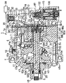
以下、本発明の実施例1を説明するが、先ず、図2〜6を参照して先願発明に係る可変容量型圧縮機用の制御弁の各実施形態について説明する。図2及び図3は、その第一の実施形態の制御弁100を備えた可変容量型圧縮機1を示しており、図2は、該可変容量型圧縮機1の吐出通路が開いた状態を示す縦断面図、図3は、吐出通路が閉じた状態を示す縦断面図である。
【0010】
図2に示すように、可変容量型圧縮機1のシリンダブロック2の一端面には、バルブプレート2aを介してリヤハウジング3が、他端面には、フロントハウジング4がそれぞれ固定される。シリンダブロック2には、シャフト(回転軸)5を中心に周方向の所定間隔おきに複数のシリンダボア6が配設される。該シリンダボア6内には、それぞれピストン7が摺動可能に収容される。
【0011】
フロントハウジング4内には、クランク室8が形成され、該クランク室8内には斜板10が収納される。該斜板10の摺動面10aには、コネクティングロッド11の球体状の一端部11aを相対転動可能に支持するシュー50がリテーナ53で保持される。リテーナ53は、ラジアル軸受55を介して斜板10のボス部10bに装着され、斜板10に対して相対回転可能である。
ラジアル軸受55は、ねじ45で固定されるストッパ54によってボス部10bに抜け止めされている。コネクティングロッド11の他端部11bはピストン7に固定されている。シュー50は、コネクティングロッド11の一端部11aの先端面を相対転動可能に支持するシュー本体51と、コネクティングロッド11の一端部11aの後端面を相対転動可能に支持するワッシャ52とで構成されている。
【0012】
リヤハウジング3には、吐出室12と吸入室13とが形成されている。該吸入室13は、吐出室12を包囲するように配置されている。前記リヤハウジング3には、エバポレータ(図示省略)の出口に通じる吸入口(図示省略)が設けられている。図2は、吐出通路39が開いた状態を示し、図3は該吐出通路39が閉じた状態を示している。
前記吐出室12と吐出口1aとを連通する吐出通路39の途中には、スプール弁(吐出制御弁)31が設けられており、吐出通路39は、リヤハウジング3に形成された通路39aと、バルブプレート2aに形成された通路39bとで構成され、該通路39bは、シリンダブロック2に形成された吐出口1aに通じている。
【0013】
有底筒状のスプール弁31内にはばね(付勢部材)32が収容され、前記リヤハウジング3にキャップ59で固定されたストッパ56にはばね32の一端が当接し、該ばね32の他端はスプール弁31の底面に当接している。該スプ一ル弁31の内部空間33は、通路34を介してクランク室8に連通している。
【0014】
前記スプール弁31の一方(上側)には、ばね32の付勢力とクランク室8の圧力が閉弁方向(弁開度が小さくなる方向)に作用する。一方、前記スプール弁31の開弁時には吐出口1aと吐出室12は、吐出通路39を介して連通しているため(図2参照)、このときのスプール弁31の他方(下側)には、吐出口1aの圧力及び吐出室12の圧力が開弁方向(弁開度が大きくなる方向)に作用する。
但し、クランク室8と吐出口1aの圧力差が所定値以下になったときには、スプール弁31が閉弁方向に移動して吐出通路39を遮断し、スプール弁31の下側には、吐出室12の圧力だけが開弁方向に作用する。すなわち、スプール弁31の下側には、吐出口1aの圧力が作用しなくなる。
【0015】
吐出室12とクランク室8とは、第二の通路57を介して連通する。該通路57の途中には、詳細を後述する本実施形態の制御弁100が圧縮機1の中心位置よりも下側に設けられている。第二の通路57は、熱負荷が大きいときには、制御弁100のソレノイド131Aの通電により弁体132が着座することによって遮断され、熱負荷が小さいときには、ソレノイド131Aへの通電停止により弁体132が弁座125aから離れることによって解放される。前記制御弁100の作動はコンピュータ(図示省略)によって制御される。
【0016】
前記吸入室13とクランク室8とは、第一の通路58を介して連通する。該通路58は、バルブプレート2aに形成されたオリフィス(第二のオリフィス)58aと、シリンダブロック2に形成された通路58bと、シャフト5に固定されたリング(環状体)9に形成された孔58cとで構成される。吸入室13とクランク室8とは第三の通路60を介して連通している。
該通路60は、フロントハウジング4に形成された通路60aと、フロント側軸受収容空間60bと、シャフト5に形成された通路60cと、シリンダブロック2に形成されたリヤ側軸受収容空間60dと、シリンダブロック2の通路58bと、バルブプレート2aのオリフィス58aとで構成される。
よって、前記シリンダブロック2の通路58bと前記バルブプレート2aのオリフィス58aは、第一の通路58の一部を構成し、且つ、第三の通路60の一部を構成する。
【0017】
前記通路60cのリヤ側端部の内周面には、雌ねじ61が形成され、該雌ねじ61には、スクリュー62がねじ込まれている。該スクリュー62には、オリフィス(第一のオリフィス)62aが形成され、該オリフィス62aの通路面積は、前記第一の通路58の一部を構成するバルブプレート2aにおける第二のオリフィス58aの通路面積よりも小さい。
したがって、斜板10のボス部10bがリング9の孔58cをほぼ塞ぎ、第一の通路58の通路断面積が大幅に減少した場合にのみ、第三の通路60を通じてクランク室8の冷媒が吸入室13に導かれる。
【0018】
前記バルブプレート2aには、圧縮室82と吐出室12とを連通させる吐出ポート16と、圧縮室82と吸入室13とを連通させる吸入ポート15とが、それぞれ周方向に所定間隔おきに設けられている。吐出ポート16は、吐出弁17により開閉され、該吐出弁17は、バルブプレート2aのリヤハウジング側端面に弁押さえ18とともにボルト19、ナット20により固定される。一方、吸入ポート15は吸入弁21により開閉され、該吸入弁21は、バルブプレート2aとシリンダブロック2との間に配設される。
【0019】
シャフト5のリヤ側端部は、シリンダブロック2のリヤ側軸受収納空間60dに収納されたラジアル軸受(リヤ側軸受)24及びスラスト軸受(リヤ側軸受)25によって回転可能に支持され、シャフト5のフロント側端部は、フロントハウジング4のフロント側軸受収容空間60bに収容されたラジアル軸受(フロント側軸受)26によって回転可能に支持される。フロント側の軸受収納空間60bには、ラジアル軸受26の他にシャフトシール46が収容されている。
【0020】
シリンダブロック2の中央部には、雌ねじ1bが設けられ、この雌ねじ1bには、アジャストナツト83が螺合する。該アジャストナット83を締め込むことによって、スラスト軸受25を介してシャフト5にプレロードを与える。また、シャフト5のフロント側端部にはプーリ(図示省略)が固定される。
【0021】
シャフト5には、該シャフト5の回転を斜板10に伝達するスラストフランジ40が固定され、該スラストフランジ40は、スラスト軸受33aを介してフロントハウジング4の内壁面に支持されている。スラストフランジ40と斜板10とは、ヒンジ機構41を介して連結され、斜板10は、シャフト5と直角な仮想面に対して傾斜可能である。斜板10は、シャフト5に摺動かつ傾斜可能に装着されている。
【0022】
ヒンジ機構41は、斜板10のフロント面10cに設けられたブラケット10eと、該ブラケット10eに設けられた直線状ガイド溝10fと、スラストフランジ40の斜板側側面40aに螺合されたロッド43とで、構成されている。ガイド溝10fの長手軸は、斜板10のフロント面10cに対して所定角度傾いている。ロッド43の球状部43aは、前記ガイド溝10fに相対摺動可能に嵌合している。
【0023】
次に、先願実施形態の可変容量型圧縮機用の制御弁(以下「制御弁」という。)100について詳細に説明する。図4は、制御弁100を可変容量型圧縮機1に組み込んだ状態を示す拡大縦断面図、図5は、図4の制御弁の詳細を示す拡大縦断面図である。
【0024】
図4に示す制御弁100は、図2及び図3の可変容量型圧縮機1のリヤハウジング3側に設けられ、該リヤハウジング3の空間84,85内に、Oリング121a,121b,131bを介して気密性を保った状態で配設される。
図5に示すように、制御弁100は、制御弁本体120と、ソレノイド励磁部130と、感圧部145とで形成されており、前記ソレノイド励磁部130は、中央部に配置され、該ソレノイド励磁部130の両側には、前記制御弁本体120と前記感圧部145とが配置されている。
【0025】
前記ソレノイド励磁部130は、その外周にソレノイドハウジング131を備え、該ソレノイドハウジング131の内部には、ソレノイド131Aと、該ソレノイド131Aの励磁によって上下方向に移動するプランジャ133と、吸引子141と、ステム138とを備え、前記プランジャ133を配置したプランジャ室130aは、前記制御弁本体120に備えられた吸入冷媒ポート129と連通している。
前記感圧部145は、ソレノイドハウジング161の下側に配置され、その内部に感圧室145aを備え、該感圧室145aは、ステム138等を介して前記プランジャ133を作動するベローズ146とばね159とを配設している。
【0026】
前記制御弁本体120は、弁室123を備え、該弁室123内には前記プランジャ133によって開閉作動する弁体132が配置されており、弁室123には、高圧の吐出圧力Pdの冷媒ガスが、通路81、吐出冷媒ポート126を介して導かれている。弁室123の底面には、クランク室冷媒ポート128に連通する弁孔125が穿設されているとともに、弁室123の上部の空間はストッパ124により閉鎖されている。該ストッパ124は、その中心部に、弁孔125と対向して該弁孔125と等しい断面積の有底縦孔の圧力室151が穿設されており、更に、該有底縦孔の圧力室151は、ばね収納室151aとして形成され、その底部には弁体132を弁室123の底面側に付勢する閉弁ばね127が配置されている。
【0027】
前記弁体132は、上部132a、拡大弁体部132b、細径部132c及び下部132dからなる棒状体で、上部132aと下部132dとが前記弁孔125と等しい断面積とされており、前記上部132aが圧力室151を有するストッパ124に嵌合支持され、前記拡大弁体部132bが弁室123内に配置され、前記細径部132cが前記弁孔内においてクランク室(クランク室圧力Pc)に連通するクランク室冷媒ポート128と対向し、前記下部132dは制御弁本体120内に嵌合支持され、その下端部が吸入圧力Psの冷媒ガスが導かれるプランジャ室130aに挿入されて前記プランジャ133に接触している。該プランジャ133が上下動することで、前記弁体132が上下動し、該弁体132の拡大弁体部132bが、弁孔125の上面の弁座125aとの間の間隙を調整する。
【0028】
そして、プランジャ室130aに導かれた低温の吸入圧力Psは、後述する感圧部145内に導かれるとともに、前記リヤハウジング3とソレノイドハウジング131間の吸入圧力導入空間85にも導かれる(図3)。該吸入圧力導入空間85は、ソレノイドハウジング131の側部に設けられる突部131aのOリング131bを介して密閉されており、前記吸入室13側からの低温の冷媒ガスによってソレノイドハウジング131の側面全体の冷却を図っている。
【0029】
制御弁本体120にかしめて結合されるソレノイドハウジング131内部には、図5に示すように、前記弁体132を接触固定するプランジャ133が配設され、該プランジャ133は、前記制御弁本体120の端部にOリング134aを介して密接状態に接するパイプ136に摺動自在に支持されている。
プランジャ133の下端部に形成される収容孔137には、ステム138の上部138Aが挿通固定されるとともに、前記ステム138の下部138Bは、吸引子141の上端部収容孔142側から下端部収容孔143側に突き出す状態で、吸引子141に対し摺動自在に支持されている。前記プランジャ133と前記吸引子141の上端部収容孔142との間には、プランジャ133を吸引子141側から離す方向に付勢する開弁ばね144が設けられている。
【0030】
また、ステム138の下部138Bには、感圧室145a内に配設されるベローズ146内部の一対のストッパ147,148のうち、ストッパ147側が接離自在に装着され、該ストッパ147のフランジ149と前記吸引子141側の下端部収容孔143との間には、ストッパ147を吸引子141側から離す方向に付勢するばね150が設けられている。
【0031】
感圧室145a内の吸入圧力Psが高くなり、ベローズ146の収縮により一対のストッパ147,148同士が当接することにより、ベローズ146の変位位置が規制され、この最大変位量は、前記ステム138の下部138Bとベロズ146のストッパ147との最大嵌合量よりも小さくなるように設定される。なお、前記ソレノイド131Aには、制御コンピュ−タ(図示省略)によって制御される励磁電流を供給できるコード158が接続されている(図4)。
【0032】
また、図示のように、前記ストッパ124には、前記圧力室151に連通する横孔153が設けられ、該横孔153は、ストッパ124と制御弁本体120とによって形成される空隙部139と前記圧力室151とを連通している。他方、制御弁本体120には、前記空隙部139と吸入圧力Psの冷媒ガスが流入するプランジャ室130aとを連通するキャンセル孔155が穿設されている。
【0033】
次に、先願発明の可変容量型圧縮機1と制御弁100との作動について説明する。車載エンジンの回転動力は、ベルト(図示省略)を介してプーリ(図示省略)から前記シャフト5に常時伝達され、シャフト5の回転力は、スラストフランジ40、ヒンジ機構41を経て斜板10に伝達され、該斜板10を回転させる。
【0034】
斜板10の回転によりシュー50が斜板10の摺動面10a上を相対回転し、ピストン7の直線往復運動に変換され、その結果シリンダボア6内の圧縮室82の容積が変化し、この容積変化によって冷媒ガスの吸入、圧縮及び吐出が順次行われ、斜板10の傾斜角度に応じた容量の冷媒ガスが吐出される。
【0035】
まず、熱負荷が大きくなる場合には、吐出室12からクランク室8に冷媒ガスの流入が阻止され、クランク室8の圧力は低く、圧縮行程中のピストン7のリヤ面に生じる力は小さくなり、ピストン7のリヤ面に生じる力の総和が、ピストン7のフロント面(トッブ面)に生じる力の総和を下回ることによって、斜板10の傾斜角度が大きくなる。
【0036】
ここで、吐出室12の圧力が高くなって、吐出室12とクランク室8との圧力差が所定値以上になり、スプール弁31の下側に作用する吐出室12の冷媒ガスの圧力が、スプール弁31の上側に作用するクランク室8の冷媒ガスの圧力とばね32の付勢力の合力に打ち勝つ場合には、スプール弁31が開弁方向に移動して吐出通路39が開き(図2)、吐出室12の冷媒ガスが、吐出口1aからコンデンサ88に流出する。なお、斜板10の傾斜角度が最小から最大になるときには、斜板10のボス部10bがリング9の孔58cから離れ、第一の通路58が全開になり、クランク室8の冷媒ガスが第一の通路58を介して吸入室に流れるため、クランク室8の圧力低下が起こる。
また、第一の通路58の通路面積が最大になると、第三の通路60から吸入室13には冷媒ガスがほとんど流れない。
【0037】
このように、熱負荷が大きくなり、制御弁100のソレノイド131Aが励磁される場合には、プランジャ133が、吸引子141側に引き込まれ、プランジャ133に接触している弁体132が弁孔125を閉じる方向に移動し、クランク室8の流入は阻止される。
一方、低温の冷媒ガスは、吸入室13に連通する通路80側から制御弁本体120の吸入冷媒ポ−ト129及びプランジャ室130aを介して感圧部145に導かれ、感圧部145のベローズ146は、吸入室13の吸入圧力Psである前記冷媒ガスの圧力に基づいて変位し、該変位が前記ステム138、前記プランジャ133を介して前記弁体132に伝達される。
すなわち、前記弁体132の前記弁孔125に対する開度位置は、前記ソレノイド131Aによる吸引力と、前記ベローズ146の付勢力と、前記閉弁ばね127及び開弁ばね144の付勢力とによって決定される。
【0038】
そして、前記感圧室145a内の圧力(吸入圧力Ps)が高くなると、前記ベローズ146が収縮し、これが前記ソレノイド131Aによる前記プランジャ133の吸引方向と一致するため、ベローズ146の変位に前記弁体132の移動が追従し、前記弁孔125の開度が減少する。これにより、吐出室12から弁室123内に導かれる高圧の冷媒ガスの量は減少(クランク室圧力Pcが低下)し、斜板10の傾斜角度が増加する(図2)。
また、前記感圧室145a内の圧力が低くなると、前記ベローズ146は、ばね159とベローズ146自身の復元力により伸長し、弁体132が弁孔125の開度を増加する方向に移動して、弁室123内に導かれる高圧の冷媒ガスの量が増大(クランク室圧力Pcが増加)し、図2の状態における斜板10の傾斜角度は減少する。
【0039】
これに対し、熱負荷が小さくなる場合には、高圧の冷媒ガスが吐出室12からクランク室8に流出し、該クランク室8の圧力が高くなる。そして、圧縮行程中のピストン7のリヤ面に生じる力が大きくなり、ピストン7のリヤ面に生じる力の総和が、ピストン7のフロント面に生じる力の総和を上回ることによって斜板10の傾斜角度が小さくなる。
【0040】
ここで、前記吐出室12とクランク室8との圧力差が所定値以下になり、スプール弁31の上側に作用するクランク室8の圧力とばね32の付勢力との合力が、スプール弁31の下側に作用する吐出室12の冷媒ガスの圧力に打ち勝つ場合には、スプール弁31が閉弁方向に移動して吐出通路39を遮断し(図3)、吐出口1aからコンデンサ88への冷媒ガスの流出が阻止される。
なお、斜板10の傾斜角度が最大から最小となるときには、斜板10のボス部10bがリング9の孔58cをほぼ塞ぎ、第一の通路58の通路断面積を大幅に減少させるが、クランク室8内の冷媒ガスは第三の通路60を通じて吸入室13に流れるため、クランク室8内の過度の圧力上昇は抑制され、圧縮機1内における冷媒ガスの循環が可能になる。
【0041】
すなわち、この場合に冷媒ガスは、吸入室13、圧縮室82、吐出室12、第二の通路57、クランク室8及び第三の通路60を経て再び吸入室13に戻る。本実施形態では、吐出制御弁としてのスプール弁31の一方に、クランク室8の圧力を作用させ、スプール弁31の他方に吐出室12の圧力を作用させる構造を採用し、スプール弁31として閉弁方向に付勢する比較的小さなばね力を有するばね32を用いており、熱負荷が小さくなって吐出室12の圧力が次第に低下したときには最小ピストンストローク(極低負荷)になり、斜板10が第一の通路58の通路面積を減少させるまで、スプール弁31は開いた状態に保たれる。
【0042】
このように、熱負荷が小さくなり、前記ソレノイド131Aが消磁される場合には、プランジャ133に対する吸引が消失し、前記開弁ばね144の付勢力により、前記プランジャ133が前記吸引子141側から離れる方向に移動し、弁体132が、制御弁本体120の弁孔125を開放する方向に移動し、クランク室8への流入が促進される。
【0043】
ここで、前記感圧部145内の圧力が上昇すると、前記ベローズ146が収縮し、弁体132の開度が減少するが、前記ステム138の下部138Bは、前記ベローズ146のストッパ147に対して接離自在に装着されているため、前記ベローズ146の変位が弁体132に対して影響を与えることはない。
【0044】
以上のように本実施形態の制御弁100は、中央部に、ソレノイド131Aの励磁によって上下方向に移動するプランジャ133を備えたソレノイド励磁部130と、該ソレノイド励磁部130の下側にステム138等を介してプランジャ133と連動するベローズ146を配設した感圧部145と、前記ソレノイドハウジング131の上側にプランジャ133と連動する弁体132等を配設した弁室123を有する制御弁本体120とによって形成されているため、感圧室145aとソレノイド131Aとが接近配設され、ソレノイド131Aの吸引による作用点とベローズ146による作用点とが近づき、作動杆を構成する弁体132及びステム138の閉弁方向への移動時におけるガタ付きを必要最小限に抑えることができる。
【0045】
図6は、先願発明の制御弁の第二の実施形態の詳細を示す縦断面図である。本実施形態では、主として吸引子と感圧部の構成に特徴を有するので、以下、この点について詳細に説明する。
本実施形態の可変容量型圧縮機用の制御弁100の吸引子141は、ソレノイド励磁部130の内側に係合される筒状部141bと、該筒状部141bの上端にて圧入される蓋部141cと、前記筒状部141bの下側にて係合されるアジャスティングスクリュー157とから構成され、これらで囲まれる内側に感圧部145が備えられている。
【0046】
つまり、筒状部141bは、その下方側からアジャスティングスクリュー157に係合される一方で、その上方側からは、ストッパ148、ばね159、ベローズ146及びストッパのフランジ149、並びにばね150が装入され、筒状部141bの上端において蓋部141cが圧入される。そして、筒状部141bとパイプ136との接合部分がTIG溶接され、感圧室145aが、吸引子141の内側に形成されるので、長手軸方向の短縮化による制御弁100のコンパクト化等を図ることができる。なお、アジャステイングスクリユー157により、ベローズを伸縮させる。
【0047】
また、本実施形態のプランジャ133は、その内部の長手軸方向に冷媒抜き孔133fが備えられているとともに、その外側面の長手軸方向には、吸入圧力Psの冷媒を感圧部145に導入させるスリット133aが備えられている。さらに、本実施形態の制御弁100に用いられているステム140は、その断面が略半月状の形状をなしているものであり、このプランジャ133のスリット133a及びステム140を介して、プランジャ室130a内の吸入圧力Psの冷媒が感圧部145に導入等されている。
【0048】
さらに、本実施形態の制御弁本体120とソレノイド励磁部130とは、上述した第一実施形態と異なり、パイプ136及びスペーサ156を介して、制御弁本体120側がかしめられて結合されている。なお、制御弁本体120とソレノイド励磁部130との間には、パッキン134bによるシールがなされている。
【0049】
ところで、上記図6に示される実施形態では、感圧部における感度調節は、アジャスティングスクリュー157に形成されたドライバ溝157bに、工具(ドライバ)をあてがって回転操作する。しかし、上記手段によれば、多くの制御弁を工具により個々に調整することは、別途工具を要するばかりでなく、多くの手数を要し、効率的ではない。そこで、制御弁を構成する感圧部の感度調節手段を簡略・容易にするために、下記の実施形態を提供する。
【0050】
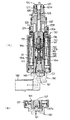
本発明の実施例1の制御弁を、特に、図1(A)、(B)及び図7(A)、(B)、(C)に示す。なお、図1に示す符号で図6に示す符号と同一のものは同一部材を表すものとする。
上記先願発明2の制御弁において、感圧部145は、感圧部145を支持する枠体、即ち、吸引子141に対して進退調節可能にアジャスティングスクリュー157が設けられ、該アジャスティングスクリュー157により、感圧体、即ち、ベローズ146を伸縮させて感度を調節可能としている。また、アジャスティングスクリュー157は、ソレノイド励磁部130を構成するコイルアセンブリ180に付設した係合部181に係合している。
【0051】
上記構成において、制御弁は、吸引子141に対して、コイルアセンブリ180を回転させることにより、アジャスティングスクリュー157を回転させ、ベローズ146を伸縮させる。なお、コイルアセンブリ180には、コネクタ182を合成樹脂により一体成形(モールド成形)させている。
【0052】
また、コイルアセンブリ180及びコネクタ182は、ソレノイドハウジング161と共にソレノイド励磁部130を密封することになるから、ソレノイド励磁部130の防水・気密性などのシール性の観点からも本発明の実施形態は望ましいものである。
なお、本発明は、ベローズを用いない他の感圧体の場合でも適用できるものである。また、感圧部145を支持する枠体が、吸引子141でない、他の枠体の場合も適用できることは言うまでもない。
【0053】
【実施例2】
ところで、上記実施例1においては、可変容量型圧縮機用の制御弁を構成する感圧部の感度調節手段を簡略・容易にするために、種々の改善を行ったが、弁体の開閉、即ち弁体132の上下動はそれぞれ弁体132とは別部材の独立した部材であるステム138及びプランジャ133を介して弁体132の上下動として伝達されるため、感圧部145及びソレノイド励磁部130の作動が弁体132に確実に伝わらないことがあり、弁体132の開閉動作の確実性が低くなることがある。
【0054】
そこで、実施例2では、実施例1において感圧部145及びソレノイド励磁部130の作動が弁体に確実に伝わるようにすることを課題とするもので、実施例1の構成部材であるステム138、プランジャ133、及び弁体132を一体物とすることで、制御弁全体の構成を簡略にすると共に、感圧部145及びソレノイド励磁部130の作動を弁体に確実に伝えて、弁体の開閉動作を正確にすることにある。
【0055】
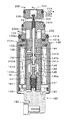
次に、図8を用いて実施例2の詳細を説明する。なお、実施例2において、実施例1と基本的に同一構成の部分には、図1に用いた図面符合と同一の符号を図8に付すことで、その説明を省略する。
実施例2の制御弁200は、弁本体220と、プランジャ133を磁力により摺動させるソレノイド励磁部130と、感圧体(ベローズ)146を具備する感圧部145と、前記ソレノイド励磁部130と感圧部145によって作動される弁体232とを備える。弁体232は、弁本体232に離接して弁孔225を開閉させる弁部232aと、弁孔225に位置する径小部232eと、プランジャ133に固定されるプランジャ一体部232cと、ステム232dと、からなる一体物で構成される。
【0056】
また、弁部232aは、弁本体220の上端部に形成される弁室223内に位置し、該弁室223の下部に形成される弁座225aの弁孔225を上部側から開閉する。なお、弁室223はクランク室8に連通している。そして、ソレノイド励磁部130の磁力により、プランジャ133が吸引子141側に吸引された(下動した)とき、弁部232aは弁孔225にその上面から当接して閉状態とする
【0057】
実施例2の作動は、前記実施例1の動作と基本的に同じであるが、弁体232は、弁部232aと、径小部232eと、プランジャ133に固定されるプランジャ一体部232cと、ステム232dとからなる一体物で構成されることから、ソレノイド励磁部130及び感圧体146からの作動が、弁部232aに直接的に伝わるために、弁部232aの開閉が円滑かつ正確となる。
【0058】
また、実施例1の閉弁ばね127に相当する部材、及び、該閉弁ばね127の受け部に相当する構成が弁本体220に不要となるために、全体の構成が簡略化すると共に可動部材が少なくなることから、トラブルも少なくなり、制御弁100全体として、メンテナンスも容易となる。
【0059】
【発明の効果】
以上の説明から理解されるように、本発明に係る可変容量型圧綿機用の制御弁によれば、吸引子に対して、コイルアセンブリを回転させることにより、アジャスティングスクリューを回転させ、ベローズを伸縮させて感圧度を調節することができる。また、コイルアセンブリには、コネクタを一体に形成させたから、アジャスティングスクリューの回転は容易となり、また、コイル部のシール性も向上するから、腐蝕の惧れも少なくなる。
また、弁体のプランジャ及び感圧部への追従性が向上するばかりでなく、閉弁ばねや該閉弁ばねのバネ受けが不要になり構成が簡略化する。
【図面の簡単な説明】
【図1】本発明の実施形態の制御弁の要部縦断面図(A)及び要部詳細図(B)。
【図2】本発明の先願発明の可変容量圧縮機の吐出通路が開いた状態を示す縦断面図。
【図3】図2の可変容量圧縮機の吐出通路が閉じた状態を示す縦断面図。
【図4】図2の可変容量型圧縮機用の制御弁の拡大縦断面図。
【図5】図4の実施形態の別例の拡大縦断面図。
【図6】図1の制御弁の要部の組立前(A)と組立後(B)の説明図。
【図7】図1に示す制御弁の正面図(A)、側面図(B)及び底面図(C)。
【図8】実施例2の拡大縦断面図。
【符号の説明】
Ps・・吸入圧力 Pc・・クランク室圧力 Pd・・吐出圧力
1・・・可変容量型圧縮機 1a・・吐出口 1b・・雌ねじ
2・・ シリンダブロック 2a・・バルブプレート
3・・リヤハウジング 4・・フロントハウジング
5・・ シャフト(回転軸) 6・・シリンダボア
7・・ピストン 8・・クランク室 9・・リング(環状体)10・・斜板 10a・・摺動面 10b・・ボス部
10c・・フロント面 10e・・ブラケット 10f・・直線状ガイド溝
11・・コネクティングロッド 11a・・一端部 11b・・他端部
12・・吐出室 13・・吸入室 15・・吸入ポート
16・・吐出ポート 17・・吐出弁 18・・弁押さえ
19・・ボルト 20・・ナット 21・・吸入弁
24・・ラジアル軸受(リヤ側軸受) 25・・スラスト軸受(リヤ側軸受)
26・・ラジアル軸受(フロント側軸受)
31・・スプール弁(吐出制御弁) 32・・ばね(付勢部材)
33・・内部空間 33a・・・スラスト軸受 34・・通路
39・・吐出通路 39a・・通路 39b・・通路
40・・スラストフランジ 40a・・斜板側側面 41・・ヒンジ機構
43・・ロッド 43a・・球状部 45・・ねじ
46・・シャフトシール 50・・シュー 51・・シュー本体
52・・ワッシャ 53・・リテーナ 54・・ストッパ
55・・ラジアル軸受 56・・ストッパ 59・・キャップ
57・・第二の通路 58・・第一の通路
58a・・オリフィス(第二のオリフィス) 58b・・通路
58c・・孔 59・・キャップ
60・・第三の通路 60a・・通路 60b・・フロント側軸受収容空間
60c・・通路 60d・・リヤ側軸受収容空間
61・・雌ねじ 62・・スクリュー
62a・・オリフィス(第一のオリフィス)
80,81・・通路 82・・圧縮室 83・・アジャストナツト
84,85・・空間(吸入圧力導入空間) 88・・コンデンサ
100・・・(可変容量型圧縮機用の)制御弁
120・・・制御弁本体 121a,121b・・Oリング
123・・・弁室 124・・ストッパ 125・・・弁孔
125a・・弁座 126・・吐出冷媒ポート 127・・・閉弁ばね
127・・閉弁ばね 128・・クランク室冷媒ポート
129・・吸入冷媒ポート
130・・・ソレノイド励磁部 130a・・プランジャ室
131・・ソレノイドハウジング 131A・・ソレノイド
131a・・突部 131b・・・Oリング
132・・・弁体 132a・・上部 132b・・拡大弁体部
132c・・細径部 132d・・下部
133・・・プランジャ 133a・・・スリット 133f・・冷媒抜き孔
134a・・Oリング 134b・・パッキング 136・・パイプ
137・・収容孔
138・・ステム 138A・・上部 138B・・下部
139・・空隙部 140・・・ステム
141・・・吸引子 141b・・筒状部 141c・・蓋部
142・・上端部収容孔 143・・下端部収容孔 144・・開弁ばね
145・・・感圧部 145a・・感圧室 146・・ベローズ
147,148・・ストッパ 149・・フランジ 150・・ばね
151・・・圧力室 151a・・ばね収納室 153・・横孔
155・・キャンセル孔 156・・スペーサ
157・・アジャスティングスクリュー
157a・・スクリュー部 157b・・ドライバ溝
158・・コード 159・・ばね 161・・ソレノイドハウジング180・・コイルアセンブリ 181・・係合部 182・・コネクタ
200・・制御弁(実施例2)
220・・・弁本体
223・・・弁室 225・・・弁孔 225a・・弁座
232・・・弁体 232a・・弁部 232b・・弁棒部
232c・・プランジャ一体部 232d・・ステム
232e・・径小部[0001]
TECHNICAL FIELD OF THE INVENTION
The present invention relates to a control valve for a variable displacement compressor used in an air conditioner of a vehicle or the like, and particularly to a control valve for a variable displacement compressor that controls supply of refrigerant gas in a crank chamber from a discharge pressure region as needed. The present invention relates to a control valve and a means for adjusting and setting sensitivity in a pressure sensing portion and a valve body structure.
[0002]
[Prior art]
2. Description of the Related Art Conventionally, a variable displacement compressor having a cylinder, a piston, a swash plate and the like compresses and discharges a refrigerant gas of an air conditioner for an automobile as disclosed in, for example, Japanese Patent Application Laid-Open No. 9-268973. The variable displacement compressor is provided with a refrigerant gas passage communicating the discharge pressure region and the crank chamber, and changes the inclination angle of the swash plate by adjusting the pressure in the crank chamber. Then, there is known one configured to change the discharge capacity. The pressure in the crank chamber is adjusted by supplying a high-pressure compressed refrigerant gas from the discharge pressure region to the crank chamber by adjusting the opening of a control valve provided in the middle of the refrigerant gas passage.
[0003]
[Problems to be solved by the invention]
As a control valve for the variable displacement compressor, the present applicant has previously proposed Japanese Patent Application No. 2001-108951 (filed on April 6, 2001, hereinafter referred to as "prior application invention"). The above-mentioned prior invention (described later) has various functions and effects, but the sensitivity adjustment in the pressure-sensitive portion is performed by applying a tool (driver) to a driver groove formed in the back of the adjusting screw. The means to do is adopted. However, according to the above-described means, individually adjusting many control valves with a tool requires not only a separate tool but also a lot of trouble and may not be efficient.
Therefore, an object of the present invention is to provide a control valve for a variable displacement compressor according to the prior application relating to the control valve for a variable displacement compressor, in which the sensitivity adjusting means of a pressure sensing portion constituting the control valve is simplified and easily provided. Is to do.
Another object of the present invention is to simplify the configuration of the entire control valve and to accurately open and close the valve body by reliably transmitting the operations of the pressure sensing unit and the solenoid excitation unit to the valve body.
[0004]
[Means for Solving the Problems]
Then, in order to solve the above-mentioned problems, a control valve for a variable displacement compressor according to the present invention employs the following means.
A control valve for a variable displacement compressor according to
[0005]
A control valve for a variable displacement compressor according to a second aspect of the present invention is the control valve for a variable displacement compressor according to the first aspect, wherein a connector of a solenoid exciting unit is integrally formed of a synthetic resin with the coil assembly. Features.
A control valve for a variable displacement compressor according to
[0006]
According to a fourth aspect of the present invention, in the control valve for a variable displacement compressor, the bellows is expanded and contracted by rotating a coil assembly or a connector with respect to the suction element. .
[0007]
A control valve for a variable displacement compressor according to claim 5, comprising a control valve main body having a valve main body, a solenoid exciting unit for sliding a plunger by magnetic force, a bellows and a stem operated by the bellows. And a control valve for a variable displacement compressor comprising: a pressure-sensitive section, wherein the sensitivity of the bellows is adjusted by an adjusting screw provided so as to be able to advance and retreat with respect to a frame supporting the pressure-sensitive section. In addition to being adjustable, an engaging portion attached to a coil assembly constituting a solenoid exciting portion is engaged with an adjusting screw so that the adjusting screw can be operated, and the frame supporting the pressure-sensitive portion is It is constituted by a suction element, and the bellows can be extended and contracted by an adjusting screw provided so as to be able to advance and retreat with respect to the suction element, and further, A valve body contacting away the valve hole of Kiben body, a plunger integral portion fixed to the plunger, characterized in that an integral and the stem.
[0008]
A control valve for a variable displacement compressor according to a sixth aspect is the control valve for a variable displacement compressor according to the first aspect, wherein the valve body which is separated from and brought into contact with the valve hole of the valve body and the plunger are slid by magnetic force. A control valve for a variable displacement compressor including a solenoid exciting section to be operated, and a pressure sensing section having a pressure sensing element and a stem operated by the pressure sensing element, the valve being fixed to the plunger. The plunger integral part and the stem are integrated.
The control valve for a variable displacement type compressor according to claim 7 is the control valve for a variable displacement type compressor according to claim 5 or 6, wherein the valve body, the plunger integrated portion, and the stem are: It is characterized by being composed of an integral object.
[0009]
BEST MODE FOR CARRYING OUT THE INVENTION
Hereinafter, a first embodiment of the present invention will be described. First, each embodiment of a control valve for a variable displacement compressor according to the prior application will be described with reference to FIGS. FIGS. 2 and 3 show the
[0010]
As shown in FIG. 2, a
[0011]
A
The
[0012]
A
A spool valve (discharge control valve) 31 is provided in the middle of a
[0013]
A spring (biasing member) 32 is accommodated in the bottomed
[0014]
On one side (upper side) of the
However, when the pressure difference between the
[0015]
The
[0016]
The
The
Therefore, the
[0017]
A
Accordingly, only when the
[0018]
The valve plate 2a is provided with a discharge port 16 for communicating the
[0019]
A rear end of the shaft 5 is rotatably supported by a radial bearing (rear bearing) 24 and a thrust bearing (rear bearing) 25 housed in a rear bearing
[0020]
A
[0021]
A
[0022]
The
[0023]
Next, a control valve (hereinafter, referred to as a “control valve”) 100 for a variable displacement compressor according to the first embodiment will be described in detail. FIG. 4 is an enlarged longitudinal sectional view showing a state where the
[0024]
The
As shown in FIG. 5, the
[0025]
The
The
[0026]
The
[0027]
The
[0028]
Then, the low-temperature suction pressure Ps guided to the
[0029]
As shown in FIG. 5, a
An
[0030]
In the
[0031]
The suction pressure Ps in the pressure-
[0032]
Further, as shown in the drawing, the
[0033]
Next, the operation of the
[0034]
The rotation of the
[0035]
First, when the heat load increases, the flow of the refrigerant gas from the
[0036]
Here, the pressure in the
When the passage area of the first passage 58 is maximized, the refrigerant gas hardly flows from the
[0037]
As described above, when the heat load increases and the
On the other hand, the low-temperature refrigerant gas is guided from the
That is, the opening position of the
[0038]
When the pressure (suction pressure Ps) in the pressure-
When the pressure in the
[0039]
On the other hand, when the heat load is reduced, the high-pressure refrigerant gas flows out of the
[0040]
Here, the pressure difference between the
When the inclination angle of the
[0041]
That is, in this case, the refrigerant gas returns to the
[0042]
As described above, when the heat load is reduced and the
[0043]
Here, when the pressure in the
[0044]
As described above, the
[0045]
FIG. 6 is a longitudinal sectional view showing details of a second embodiment of the control valve of the invention of the prior application. The present embodiment is characterized mainly by the structure of the suction element and the pressure-sensitive portion, and this point will be described in detail below.
The
[0046]
That is, the
[0047]
Further, the
[0048]
Further, unlike the first embodiment described above, the control valve
[0049]
By the way, in the embodiment shown in FIG. 6, the sensitivity adjustment in the pressure sensing portion is performed by applying a tool (driver) to a
[0050]
The control valve according to the first embodiment of the present invention is particularly shown in FIGS. 1 (A) and 1 (B) and FIGS. 7 (A), 7 (B) and 7 (C). 1 that are the same as those shown in FIG. 6 represent the same members.
In the control valve according to the second aspect of the present invention, the pressure-
[0051]
In the above configuration, the control valve rotates the adjusting
[0052]
In addition, since the
The present invention can be applied to other pressure-sensitive bodies that do not use bellows. Needless to say, the present invention can be applied to a case where the frame supporting the pressure-
[0053]
Embodiment 2
By the way, in the first embodiment, various improvements have been made to simplify and facilitate the sensitivity adjusting means of the pressure sensing part constituting the control valve for the variable displacement compressor. That is, since the vertical movement of the
[0054]
Therefore, in the second embodiment, it is an object to ensure that the operations of the
[0055]
Next, a second embodiment will be described in detail with reference to FIG. In the second embodiment, the same reference numerals as in FIG. 1 denote parts having the same configuration as in the first embodiment, and a description thereof will be omitted.
The
[0056]
The
[0057]
The operation of the second embodiment is basically the same as that of the first embodiment, except that the
[0058]
Further, since a member corresponding to the valve-closing
[0059]
【The invention's effect】
As can be understood from the above description, according to the control valve for the variable displacement type cotton wool press according to the present invention, the adjusting screw is rotated by rotating the coil assembly with respect to the suction element, and the bellows is rotated. Can be adjusted to adjust the pressure sensitivity. In addition, since the connector is formed integrally with the coil assembly, the adjusting screw can be easily rotated, and the sealing performance of the coil portion is improved, so that there is less fear of corrosion.
Further, not only the followability of the valve body to the plunger and the pressure sensing portion is improved, but also the valve closing spring and the spring receiving of the valve closing spring are not required, and the configuration is simplified.
[Brief description of the drawings]
FIG. 1 is a vertical sectional view (A) and a detailed view (B) of a main part of a control valve according to an embodiment of the present invention.
FIG. 2 is a longitudinal sectional view showing a state in which a discharge passage of the variable displacement compressor according to the invention of the prior application of the invention is opened.
FIG. 3 is a longitudinal sectional view showing a state in which a discharge passage of the variable displacement compressor of FIG. 2 is closed.
FIG. 4 is an enlarged longitudinal sectional view of a control valve for the variable displacement compressor of FIG. 2;
FIG. 5 is an enlarged longitudinal sectional view of another example of the embodiment of FIG. 4;
FIG. 6 is an explanatory view of a main part of the control valve of FIG. 1 before (A) and after assembling (B).
FIG. 7 is a front view (A), a side view (B), and a bottom view (C) of the control valve shown in FIG. 1;
FIG. 8 is an enlarged vertical sectional view of the second embodiment.
[Explanation of symbols]
Ps ··· Suction pressure Pc ··· Crank chamber pressure Pd ··· Discharge pressure
1 .... variable capacity compressor 1a ... discharge
2. Cylinder block 2a Valve plate
3. Rear housing 4. Front housing
5. Shaft (rotary axis) 6. Cylinder bore
7,
11.
12.
16. Discharge port 17
19 Bolt 20 Nut 21 Inlet valve
24 · · · radial bearing (rear bearing) 25 · · · thrust bearing (rear bearing)
26 .. Radial bearings (front side bearings)
31 Spool valve (discharge control valve) 32 Spring (biasing member)
33
39
40
43 ...
46 ・ ・
52 ・ ・
55
57 second passage 58 first passage
58a orifice (second orifice) 58b passage
58c ...
60
61 ... female screw 62 ... screw
62a orifice (first orifice)
80, 81 ...
84, 85 space (inlet pressure introduction space) 88 condenser
100 ... control valve (for variable displacement compressor)
120...
123: valve chamber 124: stopper 125: valve hole
127 ・ ・
129 ·· Suction refrigerant port
130 ... solenoid
131 ・ ・
131a ···
132:
132c-
133: plunger 133a: slit 133f: refrigerant outlet hole
134a O-
137 ··· Accommodation hole
138 ···
139 ···
141 ...
142 ··· Upper
145: Pressure-
147, 148
151:
155 ··· Cancel
157 ・ ・ Adjusting screw
200 control valve (Example 2)
220 ・ ・ ・ Valve body
223: Valve chamber 225:
232:
232c ・ ・ Plunger integrated
232e small diameter part
Claims (7)
前記感圧部は、感圧部を支持する枠体に対して進退調節可能に設けられたアジャスティングスクリューにより、前記感圧体の感度を調節可能とすると共に、ソレノイド励磁部を構成するコイルアセンブリに付設した係合部を、アジャスティングスクリューに係合させてアジャスティングスクリューを操作することを特徴とする可変容量型圧縮機用の制御弁。In a control valve for a variable displacement compressor including a control valve body, a solenoid exciting unit, and a pressure sensing unit having a pressure sensing body,
The pressure-sensitive part is a coil assembly that allows the sensitivity of the pressure-sensitive body to be adjusted by an adjusting screw that is provided so as to be adjustable with respect to a frame supporting the pressure-sensitive part, and that constitutes a solenoid excitation part. A control valve for a variable displacement compressor, characterized in that an engaging portion attached to (1) is engaged with an adjusting screw to operate the adjusting screw.
前記感圧部は、感圧部を支持する枠体に対して進退調節可能に設けられたアジャスティングスクリューにより前記ベローズの感度を調節可能とすると共に、ソレノイド励磁部を構成するコイルアセンブリに付設した係合部を、アジャスティングスクリューに係合させてアジャスティングスクリューを操作可能とし、且つ、前記感圧部を支持する枠体は吸引子により構成し、該吸引子に対して進退調節可能に設けられたアジャスティングスクリューによりベローズを伸縮可能とし、更に、上記弁本体の弁孔に離接する弁体と、上記プランジャに固定されるプランジャ一体部と、上記ステムとを一体とすることを特徴とする可変容量型圧縮機用の制御弁。A control valve for a variable displacement compressor including a control valve main body having a valve main body, a solenoid exciting part for sliding a plunger by magnetic force, and a pressure sensitive part having a bellows and a stem operated by the bellows. ,
The pressure-sensitive part is provided with a coil assembly that constitutes a solenoid excitation part, while adjusting the sensitivity of the bellows by an adjusting screw that is provided so as to be able to advance and retreat with respect to a frame supporting the pressure-sensitive part. The engaging portion is engaged with the adjusting screw so that the adjusting screw can be operated, and the frame supporting the pressure-sensitive portion is constituted by a suction element, and is provided so as to be able to advance and retreat with respect to the suction element. The bellows can be extended and contracted by the adjusting screw provided, and furthermore, a valve body which is separated from and brought into contact with the valve hole of the valve body, a plunger integrated portion fixed to the plunger, and the stem are integrated. Control valve for variable displacement compressor.
Priority Applications (1)
| Application Number | Priority Date | Filing Date | Title |
|---|---|---|---|
| JP2002259581A JP4173980B2 (en) | 2002-09-05 | 2002-09-05 | Control valve for variable capacity compressor |
Applications Claiming Priority (1)
| Application Number | Priority Date | Filing Date | Title |
|---|---|---|---|
| JP2002259581A JP4173980B2 (en) | 2002-09-05 | 2002-09-05 | Control valve for variable capacity compressor |
Publications (3)
| Publication Number | Publication Date |
|---|---|
| JP2004100473A true JP2004100473A (en) | 2004-04-02 |
| JP2004100473A5 JP2004100473A5 (en) | 2005-10-27 |
| JP4173980B2 JP4173980B2 (en) | 2008-10-29 |
Family
ID=32260538
Family Applications (1)
| Application Number | Title | Priority Date | Filing Date |
|---|---|---|---|
| JP2002259581A Expired - Fee Related JP4173980B2 (en) | 2002-09-05 | 2002-09-05 | Control valve for variable capacity compressor |
Country Status (1)
| Country | Link |
|---|---|
| JP (1) | JP4173980B2 (en) |
Cited By (5)
| Publication number | Priority date | Publication date | Assignee | Title |
|---|---|---|---|---|
| JP2006200435A (en) * | 2005-01-20 | 2006-08-03 | Fuji Koki Corp | Control valve for variable displacement compressor |
| JP2006200430A (en) * | 2005-01-20 | 2006-08-03 | Fuji Koki Corp | Electromagnetic actuator and control valve for variable displacement compressor equipped with the same |
| JP2006200426A (en) * | 2005-01-20 | 2006-08-03 | Fuji Koki Corp | Control valve for variable displacement compressor |
| EP1845260A2 (en) * | 2006-04-13 | 2007-10-17 | Fujikoki Corporation | Control valve for variable displacement compressor |
| EP2410220A2 (en) | 2010-07-21 | 2012-01-25 | Fujikoki Corporation | Control valve for variable displacement compressor |
Families Citing this family (1)
| Publication number | Priority date | Publication date | Assignee | Title |
|---|---|---|---|---|
| KR101985932B1 (en) * | 2017-08-30 | 2019-06-05 | (주)에너토크 | Valve assembly |
-
2002
- 2002-09-05 JP JP2002259581A patent/JP4173980B2/en not_active Expired - Fee Related
Cited By (9)
| Publication number | Priority date | Publication date | Assignee | Title |
|---|---|---|---|---|
| JP2006200435A (en) * | 2005-01-20 | 2006-08-03 | Fuji Koki Corp | Control valve for variable displacement compressor |
| JP2006200430A (en) * | 2005-01-20 | 2006-08-03 | Fuji Koki Corp | Electromagnetic actuator and control valve for variable displacement compressor equipped with the same |
| JP2006200426A (en) * | 2005-01-20 | 2006-08-03 | Fuji Koki Corp | Control valve for variable displacement compressor |
| JP4641190B2 (en) * | 2005-01-20 | 2011-03-02 | 株式会社不二工機 | Control valve for variable displacement compressor |
| EP1845260A2 (en) * | 2006-04-13 | 2007-10-17 | Fujikoki Corporation | Control valve for variable displacement compressor |
| EP1845260A3 (en) * | 2006-04-13 | 2009-08-26 | Fujikoki Corporation | Control valve for variable displacement compressor |
| US7690898B2 (en) | 2006-04-13 | 2010-04-06 | Fujikoki Corporation | Control valve for variable displacement compressor |
| CN101054965B (en) * | 2006-04-13 | 2011-04-20 | 株式会社不二工机 | Control valve for variable displacement compressor |
| EP2410220A2 (en) | 2010-07-21 | 2012-01-25 | Fujikoki Corporation | Control valve for variable displacement compressor |
Also Published As
| Publication number | Publication date |
|---|---|
| JP4173980B2 (en) | 2008-10-29 |
Similar Documents
| Publication | Publication Date | Title |
|---|---|---|
| JP4829419B2 (en) | Control valve for variable displacement compressor | |
| EP1995460B1 (en) | Capacity control valve | |
| KR101976857B1 (en) | Control valve for variable displacement compressor | |
| JP4160669B2 (en) | Control valve for variable displacement compressor | |
| KR20140118808A (en) | Control valve for variable displacement compressor | |
| JP2001099060A (en) | Control valve for variable displacement compressor | |
| US6769667B2 (en) | Control valve for variable-capacity compressor | |
| KR20150101962A (en) | Control valve for variable displacement compressor | |
| KR102252391B1 (en) | Variable displacement compressor and control valve thereof | |
| KR20140127162A (en) | Variable displacement compressor and mounting structure of flow sensor | |
| JP2004100473A (en) | Control valve for variable capacity type compressor | |
| JP4082802B2 (en) | Control valve for variable displacement compressor | |
| JP3461343B2 (en) | Control valve for variable displacement compressor | |
| JP4247225B2 (en) | Control valve for variable capacity compressor | |
| JP3847617B2 (en) | Control valve for variable capacity compressor | |
| JP2006118508A5 (en) | ||
| JP2004204759A (en) | Displacement control valve | |
| JP2003328935A (en) | Control valve for variable displacement compressor | |
| JP2003166666A (en) | Control valve for variable displacement compressor | |
| JP2001041154A (en) | Control valve for variable-displacement compressor | |
| JP6871810B2 (en) | Variable capacitance compressor control valve | |
| JP2007107451A (en) | Solenoid control valve of variable displacement swash plate type compressor | |
| JP2000193122A (en) | Control valve for variable displacement compressor | |
| JP2001082325A (en) | Control valve for variable displacement compressor | |
| JPH11125180A (en) | Swash plate variable displacement compressor |
Legal Events
| Date | Code | Title | Description |
|---|---|---|---|
| RD03 | Notification of appointment of power of attorney |
Free format text: JAPANESE INTERMEDIATE CODE: A7423 Effective date: 20041119 |
|
| A521 | Written amendment |
Free format text: JAPANESE INTERMEDIATE CODE: A523 Effective date: 20050902 |
|
| A621 | Written request for application examination |
Free format text: JAPANESE INTERMEDIATE CODE: A621 Effective date: 20050902 |
|
| TRDD | Decision of grant or rejection written | ||
| A01 | Written decision to grant a patent or to grant a registration (utility model) |
Free format text: JAPANESE INTERMEDIATE CODE: A01 Effective date: 20080812 |
|
| A01 | Written decision to grant a patent or to grant a registration (utility model) |
Free format text: JAPANESE INTERMEDIATE CODE: A01 |
|
| A977 | Report on retrieval |
Free format text: JAPANESE INTERMEDIATE CODE: A971007 Effective date: 20080814 |
|
| A61 | First payment of annual fees (during grant procedure) |
Free format text: JAPANESE INTERMEDIATE CODE: A61 Effective date: 20080815 |
|
| R150 | Certificate of patent or registration of utility model |
Free format text: JAPANESE INTERMEDIATE CODE: R150 Ref document number: 4173980 Country of ref document: JP Free format text: JAPANESE INTERMEDIATE CODE: R150 |
|
| FPAY | Renewal fee payment (event date is renewal date of database) |
Free format text: PAYMENT UNTIL: 20110822 Year of fee payment: 3 |
|
| FPAY | Renewal fee payment (event date is renewal date of database) |
Free format text: PAYMENT UNTIL: 20110822 Year of fee payment: 3 |
|
| FPAY | Renewal fee payment (event date is renewal date of database) |
Free format text: PAYMENT UNTIL: 20120822 Year of fee payment: 4 |
|
| R250 | Receipt of annual fees |
Free format text: JAPANESE INTERMEDIATE CODE: R250 |
|
| FPAY | Renewal fee payment (event date is renewal date of database) |
Free format text: PAYMENT UNTIL: 20120822 Year of fee payment: 4 |
|
| FPAY | Renewal fee payment (event date is renewal date of database) |
Free format text: PAYMENT UNTIL: 20130822 Year of fee payment: 5 |
|
| R250 | Receipt of annual fees |
Free format text: JAPANESE INTERMEDIATE CODE: R250 |
|
| R250 | Receipt of annual fees |
Free format text: JAPANESE INTERMEDIATE CODE: R250 |
|
| R250 | Receipt of annual fees |
Free format text: JAPANESE INTERMEDIATE CODE: R250 |
|
| R250 | Receipt of annual fees |
Free format text: JAPANESE INTERMEDIATE CODE: R250 |
|
| R250 | Receipt of annual fees |
Free format text: JAPANESE INTERMEDIATE CODE: R250 |
|
| R250 | Receipt of annual fees |
Free format text: JAPANESE INTERMEDIATE CODE: R250 |
|
| R250 | Receipt of annual fees |
Free format text: JAPANESE INTERMEDIATE CODE: R250 |
|
| R250 | Receipt of annual fees |
Free format text: JAPANESE INTERMEDIATE CODE: R250 |
|
| LAPS | Cancellation because of no payment of annual fees |