JP2004100197A - Dust-collecting belt type screen device - Google Patents
Dust-collecting belt type screen device Download PDFInfo
- Publication number
- JP2004100197A JP2004100197A JP2002261263A JP2002261263A JP2004100197A JP 2004100197 A JP2004100197 A JP 2004100197A JP 2002261263 A JP2002261263 A JP 2002261263A JP 2002261263 A JP2002261263 A JP 2002261263A JP 2004100197 A JP2004100197 A JP 2004100197A
- Authority
- JP
- Japan
- Prior art keywords
- screen
- belt
- sprocket
- frame
- shaft piece
- Prior art date
- Legal status (The legal status is an assumption and is not a legal conclusion. Google has not performed a legal analysis and makes no representation as to the accuracy of the status listed.)
- Pending
Links
Images


Abstract
Description
【0001】
【発明の属する技術分野】
本発明は、河川や水処理施設等の取水口に設置される除塵用ベルト式スクリーン装置に関する。より詳しくは、本発明は、水透過性のスクリーンを無端状に走行させて、流水中の夾雑物をスクリーン上に掻き揚げる除塵用ベルト式スクリーン装置に関する。
【0002】
【従来の技術】
従来から、水域の美観あるいは水処理負荷の軽減のために、河川や水処理施設等の取水口に鋼線で形成された金網状のベルトまたは帯板で形成された略波形のベルトを備えたベルト式スクリーン装置を設置して、水面及び水中に浮遊する木の葉や枝、ペットボトル、ビニルシート等の各種夾雑物を無端ベルトで掻き揚げて回収した後に、夾雑物を処分していた。
かかる夾雑物を掻き揚げる除塵用ベルトとしては、図9(A)に示すような、長さ方向において交互に反対側に屈曲させて山部aと谷部bとを連続して形成した適宜幅の帯板cの多数を同方向に並列させて、隣接する帯板cの山部a及び谷部bを互いに嵌合し、その重合部に軸片dを挿通して屈折自在に連結して所望長さのベルトeに形成したものが知られている(例えば、特許文献1参照)。このベルトe上には、適宜の間隔を存して掻揚用アングル部材fが設けられている。
以上のようなベルトeは、図9(B)に示すように、河川gの流れに対して下流側に傾斜してスプロケットhと転胴iの間に掛け渡される。ベルトeの上流側背面には、フラットバーjが掻揚装置の本体フレームに支持されることなく配置される。そして、モータkに連動してスプロケットhを回転させてベルトeを無端状に走行させながら、河川gに浮遊する夾雑物をアングル部材fで掻き揚げ、セパレータmの回転によりベルトeから夾雑物を分離して回収する。
【0003】
【特許文献1】
実開昭62−148620号公報
【0004】
【発明が解決しようとする課題】
除塵用ベルトは河川等の水流による水圧を受けるため、ベルトに撓みが発生する。また、除塵用ベルトが設置される取水口の水路幅及び深さは必ずしも一定でないため、無端ベルトの機械幅及び機械長は水路の大きさに対応させる必要がある。しかしながら、略波形の帯板からなる従来の無端ベルトの機械幅及び機械長を共に大きくとると、水圧によりベルトを構成する帯板に亀裂等が発生するという問題があった。
しかも、従来の無端ベルトは、その上流側背面にフラットバーを本体フレームに支持することなく配置して、その両側縁部に駆動用スプロケットを係合するチェーンが取り付けられている。そのため、ベルトが例えば流水の流速1m/秒以上に対応する水圧負荷を受けた場合、ベルトの両側部は撓みが大きくなり、軸片が変形したり帯板に亀裂等が発生するという問題があるだけでなく、無端ベルトの走行性が悪化するという問題があった。
そこで、本発明の目的は、長期にわたって運転してもベルト式スクリーンに亀裂が発生したりその軸片が変形することがなく、取水口の水路幅及び深さや流水の水圧及び流速による制約が大幅に緩和され、円滑に走行可能なスクリーンを備えた除塵用ベルト式スクリーン装置を提供することにある。
【0005】
【課題を解決するための手段】
本発明は、長さ方向に交互に反対側に屈曲させて山部と谷部とを連続して形成した多数の帯板を同じ方向に並列させて、隣接する帯板の山部と谷部を互いに嵌合し、それらの重合部に軸片を挿通して屈折自在に連結したベルト式スクリーンと、該スクリーンの軸片に係合する駆動スプロケットと、該スプロケットを軸支するスクリーンフレームと、駆動スプロケットとの間にスクリーンが掛け渡される下部ロータとを備え、スプロケットの回転駆動によりスクリーンを無端状に走行させて、流水中の夾雑物をスクリーン上に掻き揚げる除塵用ベルト式スクリーン装置において、上記軸片が挿通する穴を有する複数の小判状補強プレートをスクリーンの幅方向に介装すると共に、表面が樹脂製部材で形成されるかまたは樹脂で被覆された長尺板からなるベルト受けレールを水流に関してスクリーンの下流側に配置してスクリーンを摺動自在とし、かつ該レールが支持部材を介してスクリーンフレームに固定されていることを特徴とする。
本発明においては、所定の間隔で上方に突出する爪片を有する複数の矩形状板片が上記スクリーン上の幅方向に配置され、これらの板片がスクリーンの長さ方向に所定の間隔で並設されている。また、水流に対して上流側に位置するスクリーンの幅方向の下端部表面に当接するブラシを設けることが好ましい。
【0006】
【作用】
本発明において、スクリーンの軸片が挿通する穴を有する複数の小判状補強プレートがスクリーンの幅方向に介装されているので、スクリーンを構成する軸片の強度が補強プレートによって補強される。そのため、ベルト式スクリーンが河川等の水流による比較的大きな水圧を受けても、上記軸片の撓みに起因する帯板の亀裂等の発生を防止することができる。従って、スクリーン面積を大きくすることが可能となり、取水口の水路幅及び深さに制約を受けることがない。
また、長尺板からなるベルト受けレールが水流に関してスクリーンの下流側に配置されてスクリーンフレームに固定されているので、上流側からの水圧負荷をレールで受け止めることができる。例えば、上記フレームに支持されることなくスクリーンの両側部にチェーンを掛け渡した設けた場合、ベルト式スクリーンは、流水の通過流速1m/秒前後までしか耐えられないが、ベルト受けレールを支持部材を介してフレームに固定することによって、通過流速が3〜4m/秒であっても機能上の制約を受けるようなことがない。即ち、上記軸片が変形することがなく、しかも、レールは表面が樹脂製部材または樹脂被覆の長尺板で構成されているので、比較的大きな水圧負荷を受けてもスクリーンは円滑に走行する。
このように、本発明のスクリーン装置は、スクリーンを構成する帯板の亀裂等の発生や軸片の変形を防止しつつ、取水口の水路や流水の流速の制約が大幅に緩和される。そして、スプロケットの回転駆動により略波形の帯板からなる無端スクリーンが屈折自在に走行する際、河川等の水面及び水中に浮遊しながら流れてくる夾雑物がスクリーン上に掻き揚げられ、河川等の水は浄化される。
【0007】
請求項2に係る発明によれば、所定の間隔で上方に突出する爪片を有する複数の矩形状板片がスクリーン上の幅方向に配置され、同板片がスクリーンの長さ方向に所定の間隔で並設されたものであるから、水面から一旦掻き揚げられた夾雑物は水と一緒に落下するようなことがなく、夾雑物を確実に回収することができる。因みに、従来の鋼線で形成された金網状のベルトでは、小さな夾雑物がベルトに絡み付き、夾雑物を分離しにくいという問題がある。また、掻揚用アングル部材を取り付けたベルトでは、一旦掬い揚げられた夾雑物、特に木の葉等が落下する水流と一緒に流されるという問題がある。
請求項3に係る発明によれば、水流に対して上流側に位置するスクリーンの幅方向の下端部表面に当接するブラシを設けたものであるから、流水中の夾雑物をスクリーンの下方から下流側に流失させる恐れがない。また、スクリーン上に取り付けられた爪片はブラシの線間を通過するので、無端スクリーンの走行が妨げられることがない。
【0008】
【発明の実施の形態】
以下、本発明を詳細に説明する。
本発明の除塵用ベルト式スクリーン装置は、駆動スプロケットと下部ロータとの間にベルト式スクリーンが掛け渡され、モータ等の駆動源から適宜の動力伝達機構を介してスプロケットを回転駆動させることにより、スクリーンが無端状に走行する。駆動スプロケットから反転走行するスクリーンの下方には、その下面に接触する回転式セパレータブラシが配置されていて、上記伝達機構を介してセパレータブラシを回転駆動させることにより、スクリーン上に掻き揚げられた夾雑物がスクリーンから分離され、適宜の容器に回収される。
動力伝達機構としては、駆動源の出力軸と駆動スプロケット軸及びセパレータブラシ軸とを連動させるベルト伝動、Vベルト伝動、チェーン伝動、歯車機構等があり、駆動源から得られる駆動スプロケットの駆動力を同様の手段によってセパレータブラシ軸に伝動させてもよい。セパレータブラシは、必要に応じて複数並設してもよく、その場合、上述の動力伝達機構が順次セパレータブラシ間に連設される。セパレータブラシの軸方向に沿って半径方向に取り付けられるブラシ自体は、通常軸に関して対称位置に配置される。
【0009】
本発明のスクリーン装置は、スクリーンが垂直状に直立して上部が水平方向に屈曲しているか、あるいは、スクリーンが水流に対して下流側に傾斜し、それから連続して水平方向に屈曲していて、屈曲部にスクリーンを支持する回転体が配置される。この回転体(ロータ)及び前記下部ロータは、連続した回転体であってもスペーサを介して複数に分割したものでもよい。
本発明において、夾雑物が掻き揚げられるスクリーンとしては、図9に示すような前述の帯片と軸片とから形成されるベルト式スクリーンが用いられる。しかし、山部と谷部の屈曲形状は、図9に示す角形に限定されるものではなく、円弧状等の波形であってもよい。かかるスクリーンは、取水口の水路幅及び深さに対応したサイズとされる。
スクリーンの幅方向には、スクリーンの軸片が挿通する穴を有する小判状の補強プレートが複数介装される。補強プレートは、通常スクリーンの幅方向両端及び中央部の複数箇所に介装される。これらの補強プレートは、スクリーンの長さ方向に連続して無端状に配設することが好ましいが、スクリーンの軽量化やコストの低減を図るために、不連続に配設することもできる。
更に、スクリーン上の幅方向には、所定の間隔で上方に突出する爪片を有する複数の矩形状板片が配置され、これらの板片がスクリーンの長さ方向に所定の間隔で並設されている。
【0010】
前記駆動スプロケットは、スクリーンフレームの両側に軸支され、補強プレートが介装されたスクリーンの帯片を挟み込むように軸片に係合される。そのため、スクリーンの略波形の部位にかかる荷重を補強プレートに分散でき、略波形の帯片の変形、亀裂、破損等を抑制することができる。なお、駆動スプロケット以外の下部ロータ、回転式セパレータブラシ及び屈曲部に配置される回転体も、スクリーンフレームの両側に軸支されている。
また、水流に対して上流側に位置するスクリーンの幅方向に下部ブラシを設けて、スクリーンの下端部に当接させることが好ましい。かかる部位にブラシを設けておくと、スクリーンの下方が開放状態であるかまたはゴム板を配置する従来のスクリーン装置と異なって、流水中の夾雑物がスクリーンの下方を通過して下流側に流失するようなことはない。しかも、スクリーン上に取り付けられる爪片は下部ブラシの線間を通過するので、無端スクリーンは円滑に走行することができる。
スクリーンの幅方向中央部に介装される前記補強プレートの配設箇所は、水圧負荷を受けるスクリーンの帯板に亀裂等の損傷が発生しないような位置であれば、特に限定されるものではない。
【0011】
前記爪片を有する板片において、板片に対する爪片の角度は、スクリーンが水流に対して下流側に傾斜している場合、90°に直立することが好ましいが、垂直軸線に対してスクリーンの走行方向側に20°以下の範囲で傾斜させても、夾雑物の掻揚及び分離に特段の支障はない。また、スクリーンが垂直状に直立している場合、爪片の角度は、一般に45〜90°の範囲でスクリーンの走行方向側に傾斜しており、60〜85°の範囲内で傾斜していることが好ましい。上記角度が45°未満であると、スクリーンの走行方向と逆向きに回転するセパレータブラシによって夾雑物を完全に分離させることが困難である。一方、角度が90°より大きくなると、流水中の夾雑物をスクリーン上に確実に掻き揚げることが困難となる。
【0012】
上述の爪片を備えた無端スクリーンを走行させて夾雑物を水面から掻き揚げた時、従来の金網状ベルトや掻揚用アングル部材を取り付けたベルトと異なり、夾雑物が爪片に引っかかって水流により落下することがない。しかも、前記セパレータブラシの回転により夾雑物がスクリーンから容易に分離するので、夾雑物を確実に回収することができる。
上記板片は、その両側部が爪片取付ボルトとナットとで締め付けることによりクリーン上に固定される。このようなボルトとナットを用いて板片をスクリーンに固定すると、夾雑物掻揚部材が溶接等で強固に固着されていた従来のベルトと異なって、河川や水処理施設の環境が変化しても、必要に応じて爪片付き板片を交換することが可能である。
【0013】
水流に関してスクリーンの下流側面には、スクリーンが摺動する表面を樹脂製部材で形成するかまたは樹脂で被覆した長尺板からなるベルト受けレールが上下2段にわたって配置されると共に、レールを支持する複数本の支持部材がスクリーンフレームに固定されている。また、スクリーンの前記屈曲部にも、その上側にスクリーン裏面が摺動する上部レールが配置され、これを支持する複数本の支持部材がフレームに固定される。これらの支持部材としては、パイプ、棒状部材、板状部材等が用いられる。なお、下段のベルト受けレールが配置される部位のスクリーンの長さ方向に、前記板片の爪片が配置されないのはいうまでもない。
スクリーンの滑りを良くするために、低摩擦係数の樹脂材料でレール表面部材を構成することが好適であり、例えばステンレス鋼製長尺板を同樹脂材料で被覆してもよい。
樹脂材料の摩擦係数は、0.3以下であることが好ましく、0.2以下であることが更に好ましい。かかる樹脂材料としては、ナイロン、ポリイミド、ポリアミドイミド、超高分子量ポリエチレン、ポリエステル、ポリアセタール、PEEK等が挙げられる。これらの樹脂は機械的強度及び耐磨耗性にも優れている。上記樹脂の中でも、超高分子量ポリエチレン(U−PE100,U−PE300:日本ポリペンコ株式会社製)や6ナイロン(MCナイロン:日本ポリペンコ株式会社製)が好ましく用いられる。
【0014】
ところで、掻揚部材としてアングル部材を取り付けた従来のベルトでは、一旦掻き揚げられた夾雑物の水面への落下を防止するために、30°程度の傾斜角でベルトを下流側に傾斜させていた。しかし、傾斜角が小さいと、スクリーン装置の設置面積が大きくなる。
そこで、本発明の除塵用ベルト式スクリーン装置において、ベルト式スクリーンが垂直状に直立して上部が水平方向に屈曲している場合は、前述した通り、板片に対して爪片を60〜85°の範囲内で傾斜させて、板片をスクリーン上に取り付けることが望ましい。一方、スクリーンを傾斜させる場合は、水流に対して45°以上90°未満の傾斜角で下流側に傾斜させることが望ましい。上記傾斜角が90°近くになると従来のベルトと同様に夾雑物が落下する可能性があり、装置の設置面積との関係を考慮に入れて、傾斜角は50〜80°の範囲にあることが好ましく、55〜75°の範囲にあることが特に好ましい。
【0015】
【実施例】
次に、図面を参照しながら本発明を具体的に説明する。
図1,2において、符号1は河川の取水口Aに設置されるスクリーンフレームである。フレーム1は、傾斜部が水流に対して60°下流側に傾斜し上部が水平方向に折曲していて、フレーム本体を構成する傾斜部に横架された副フレーム1aと水平部に横設された上部フレーム1bと上部フレーム1b間を連結する垂直フレーム1cからなる。フレーム1の傾斜部は取水口Aの底面上に支持され、上部は複数本の支柱2で取水口Aの地盤上に支持される。上部フレーム1bの上面には架台3が取り付けられ、架台3に固定されたモータ据付フレーム4a上に減速機構を備えたモータ4が据え付けられる。
フレーム1上部の両側間に軸受を介して軸5a,6aが支承され、これらの軸5a,6aにそれぞれ複数の駆動スプロケット5及び回転式セパレータブラシ6が固設される。上記モータの出力軸4b及びスプロケット軸5aの端部にはスプロケット4c,5bが嵌着され、更にスプロケット軸5a及びセパレータブラシ軸6aの各端部にはスプロケット5c,6bが嵌着され、スプロケット4c,5b間及びスプロケット5c,6b間にそれぞれチェーン7,8が卷回される。従って、モータ4の回転駆動に伴ってスプロケット5及びセパレータブラシ6が同時に回転される。上記軸4b,5a,6a、スプロケット4c,5b,5c,6b及びチェーン7,8は、人手に直接触れないようにカバー9で覆われる。
【0016】
フレーム1下部の両側間には下部ロータ10の回転軸10aが軸受を介して支承され、前記フレーム1の折曲部内、具体的にはスクリーンの屈曲部下側にこれを支持する支持ロータ11を配置して、ロータ10と駆動スプロケット5の間にベルト式スクリーン12が掛け渡される。
スクリーン12上には、上方に突出する爪片13を有する板片が、スクリーン12の幅方向及び長さ方向に所定の間隔で複数列取り付けられていて、スクリーン12の走行時に流水中の夾雑物がスクリーン12上に掻き揚げられる。上記セパレータブラシ6の下部側方には邪魔板14が設けられていて、爪片13で掻き揚げられた夾雑物が周囲に飛散するのを防止する。
【0017】
フレーム1の傾斜部の長さ方向には2段にわたってベルト受けレールとしての前面レール15及び裏面レール16が複数列配置され、フレーム1の上部折曲部には上部レール17が複数列配置され、これらのレール15〜17上をスクリーン12が摺動する。図2には5本の前面レール15が図示されている。前面レール15は水流に対して上流側に位置し、裏面レール16は水流に対して下流側に位置する。前面レール15及び裏面レール16において、スクリーン12面が摺動する上面は樹脂製表面部材で構成されている。
前面レール15は、フレーム1の両側間に横架された複数本の固定パイプ18によって支持され、これらのパイプ18はスクリーンフレーム1の一部を構成する。裏面レール16及び上部レール17は、それぞれフレーム1の両側間に横架された複数本の固定パイプ19,20に支持される。
取水口Aの底面上に下部バッフル板21が配置され、フレーム1の両側間に取り付けられる。このバッフル板21を介して下部ブラシ22が設けられ、ブラシ22は水流に対して上流側に位置するスクリーン12の幅方向の下端部表面に当接する。
【0018】
更に、図3〜5に基づいて図1,2に示す除塵用ベルト式スクリーン装置の細部について説明する。
ベルト式スクリーン12は、図4に示すように、長さ方向に交互に反対側に屈曲させて山部23aと谷部23bとを連続して形成した多数の帯板23を同じ方向に並列させて、隣接する帯板の山部23aと谷部23bを互いに嵌合し、それらの重合部に軸片24を挿通して屈折自在に連結して所定の長さに形成した無端状のスクリーンからなる。軸片24の両端には、帯板23が抜け出ないように、軸片24より大径の抜止部材25が固着される。
【0019】
軸片24の両端に固着された抜止部材25と幅方向最外周の帯板23の間に、山部23aの高さより多少長い小判状の補強プレート26が介装される。補強プレート26は隣接する軸片24が挿通する2つの穴26aを有していて、異なる2枚の補強プレート26の端部同士を重ね合わせて穴26aの位置をずらせた状態で、ある1本の軸片24が挿通する。上記穴26aは軸片24を遊嵌可能に補強プレート26の長さ方向を長くした長穴として、スクリーン12にかかる水圧の変化に対応できるようにしてある。
また、水圧負荷を受けるスクリーン12の幅方向中央部にも、上述の補強プレート26が適宜の間隔で帯板23の間に複数枚介装される。この場合、2枚の補強プレート26が互いに対向する位置に配置され、その間に1枚の補強プレート26の端部を穴26aの位置をずらせたサンドイッチ状態で1本の軸片24が挿通する。即ち、1本の軸片24は3枚の補強プレートの穴26aを挿通する。
このように、スクリーン12の幅方向の両端及び中央部に介装される補強プレート26は、図4に示すように、スクリーン12の長さ方向に連続して無端状に複数列配置される。
【0020】
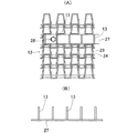
ベルト式スクリーン12上には、図5に示すように、所定の間隔で上方に突出する前記爪片13を有する板片27が取り付けられる。板片27は、細長い矩形状をなし、スクリーン12の幅方向に所定の間隔でもって複数個取り付けられ、長さ方向に所定の間隔で配列される。また、爪片13は板片27に対して直立している。
板片27は、ナットをスクリーン裏面に宛い、スクリーン表面側の板片両側部に形成された穴から爪片取付ボルト28を挿通させて締め付けることにより、スクリーン12上に固定される。
【0021】
図3において、符号29は前記スプロケット軸5aの径より僅かに幅広の長穴であり、後述のテイクアップボルトを用い、軸5aとフレーム1間の距離を調節してスクリーン12を緊張させる際に、軸5aが長穴29に沿って図面右側に移動する。
前記セパレータブラシ6は、その軸方向に固定された一対のセパレータ座6c間にブラシ6dを軸6aのほぼ全長にわたって挟持させて、座6cをブラシ取付ボルト6eで締め付けることによって形成される。図3にはブラシ6dが十字状に交叉したセパレータブラシ6の例が図示されている。なお、符号30はセパレータブラシ軸6aの径より僅かに幅広の長穴であり、テイクアップボルトを用いて、前記チェーン8を緊張させるために設けられている。前記支持ロータ11は、その軸11aがフレーム1の両側間に支承されている。
【0022】
スクリーン12の下流側面を受ける前記前面レール15及び裏面レール16の上面は、断面形状逆L字状の超高分子量ポリエチレン製レール表面部材15a,16aで構成される。各レール表面部材15a,16aは、それぞれステンレス鋼製の各レール本体(長尺板)に複数のビス15b,16bで固着され一体化されている。上部レール17の上面は、断面形状逆L字状の6ナイロン樹脂製レール表面部材17aで構成される。レール表面部材17aも、複数のレール取付ボルト17bで同様にレール本体に固着され一体化されている。
図3に図示された前記ロータ10は、スペーサ10bとロータとが交互に連設されている。また、前記バッフル板21及びスクリーン12の下端部に当接するブラシ22は、両者の上下端部を表面側取付座31aと裏面側取付座31bとで挟持して、複数のバッフル板取付ボルト32及びブラシ取付ボルト33で幅方向に締結することにより固定される。
【0023】
以上のようなスクリーン装置は、ベルト式スクリーン12が水流に対して下流側に傾斜して、その下部が水面下に没した状態で取水口Aに臨んでいる。同装置のモータ4を駆動してスプロケット6を回転させると、無端スクリーン12が矢印方向に走行し、同時にセパレータブラシ6も回転する。スクリーン12にはその幅方向及び長さ方向に小判状の補強プレート26が配置されているので、水流による水圧を受けても、スクリーン12を構成する軸片24の撓みが防止される。しかも、スクリーン12は、低摩擦係数の樹脂製前面レール15及び裏面レール16、更には上部レール17上を摺動するので、これらのレール15〜17上を円滑に走行する。
走行中のスクリーン12に流水中に浮遊する夾雑物が接触すると、夾雑物は爪片13に引っかけられスクリーン12上に掻き揚げられる。この際、下部バッフル板21が取水口Aの底面上に配置され、下部ブラシ22がスクリーン12の幅方向の下端部に当接しているので、夾雑物が下流側に逸流することはない。また、上記爪片13は下部ブラシ22の線間を通過するので、無端スクリーン12の走行に支障をきたすことがない。
掻き揚げられた夾雑物は、スクリーン12の水平部に至り、そこから反転してセパレータブラシ6の回転力によってスクリーン12から分離される。分離された夾雑物は、一部が飛散防止用の邪魔板14に衝突しながら下方に落下し、取水口Aの地面上に用意された適宜のコンテナに回収される。
【0024】
更に、本発明の別の除塵用ベルト式スクリーン装置について、図6〜8を参照しながら説明する。なお、図1〜5において説明した構成部材と同様のものには同じ符号を付し、重複した説明は避けることにする。
図6,7において、スクリーンフレーム1は、垂直状に直立し上部が水平方向に折曲している。フレーム1の上面には架台3が取り付けられ、その上に据え付けられるモータ等の伝動機構が省略されているが、本スクリーン装置においても同じ伝動機構を備えている。フレーム1上部の両側には駆動スプロケット軸5aの両端部が挿通する長穴29が形成されていて、軸5aに連結された前記テイクアップボルト41を図6の右側に移動させてスクリーン12を緊張させた後、軸5aの両端部を支承する軸受(図示せず)をフレーム1に固定する。
また、スクリーン12の水平部下側下面に外周部が接触する回転式セパレータブラシ6が2基並設され、上述のテイクアップボルトを用いて図示していないチェーン(8,8)が緊張される。更に、スクリーン12の屈曲部下側に支持ロータ11が配置される。
【0025】
スクリーン12の下流側面を受ける前面レール15及び裏面レール16は、図3に示すものと同様に表面が超高分子量ポリエチレンで構成される。上部レール17は、6ナイロン樹脂製の前記レール表面部材17aがビス17cでステンレス鋼製レール本体に一体化されている。また、下部ロータ10、下部バッフル板21及び下部ブラシ22に関しては、図1〜3に示すスクリーン装置のものと同様である。
フレーム1の前後面には、観音開き式の前面側点検扉42及び後面側点検扉43が設けられる。後面点検扉43の側部にはヒンジ44がフレームカバー45に取り付けられ、他側部に取手43aが取り付けられる。前面側点検扉42も同様の構造からなり、図6に取手42aが図示されている。また、カバー45の下端部には、セパレータブラシ6,6の軸方向に沿ってシュート46が配置される。そして、セパレータブラシ6,6の回転によってスクリーン12から分離された夾雑物は、シュート46内を通過して下方に落下し、取水口Aの地面上に用意された適宜のコンテナに回収される。
【0026】
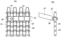
ベルト式スクリーン12上には、上方に突出する爪片47を有する板片27が取り付けられる。爪片47は、板片27に対して75°の角度でスクリーン12の走行方向側に傾斜している。
図6〜8に示す除塵用ベルト式スクリーン装置は、スクリーン12の掻揚部が垂直状に直立しているため、その上の幅方向に所定の間隔で配列される爪片47をスクリーン12の走行方向側にやや傾斜させたもので、先に説明したベルト式スクリーン装置と同様に、流水中の夾雑物をスクリーン12上に確実に掻き揚げることができる。
なお、図1〜3と図6〜8に示す各除塵用ベルト式スクリーン装置において、スクリーン12の掻揚部が傾斜しているか直立しているかに起因して、板片27に対する爪片13と爪片47の角度が相違しているが、この点を除いて、一方の構成部材を他方の装置に付加したり、あるいはそれぞれの構成部材を相互に変更することが可能である。
【0027】
【発明の効果】
本発明の除塵用ベルト式スクリーン装置によれば、スクリーンを構成する軸片の強度が小判状の補強プレートによって補強されるため、ベルト式スクリーンが水流による比較的強い水圧を受けても、長期にわたって軸片の撓みを防止することができるので、スクリーンを構成する帯板の亀裂等の発生を防止することができる。また、取水口の水路幅及び深さに制約を受けないという利点がある。
更に、水流に関して下流側のスクリーン面に当接するベルト受けレールが支持部材を介して配置されているため、スクリーンが上流側から比較的強い水圧負荷を受けても、これをレールで受け止めることができ、スクリーンを構成する軸片が変形しないだけでなく、レール表面が樹脂で形成されているため、スクリーンは円滑に走行することができる。従って、流水の水圧や流速に対する制約が大幅に緩和される。
【図面の簡単な説明】
【図1】本発明の一実施例を示す除塵用ベルト式スクリーン装置の側面図である。
【図2】図1の正面図である。
【図3】図1の要部断面図である。
【図4】本発明におけるベルト式スクリーンの一例を示し、(A)はその正面図であり、(B)は側面図である。
【図5】(A)は図1に示す爪片を有する板片が取り付けられたベルト式スクリーンの要部拡大平面図であり、(B)は板片の縦断面図である。
【図6】本発明の別の実施例を示す除塵用ベルト式スクリーン装置の側断面図である。
【図7】図6の背面図である。
【図8】図6に示す爪片を有する板片が取り付けられたベルト式スクリーンの拡大図であって、(A)はその平面図、(B)は側面図である。
【図9】(A)は従来のベルト式スクリーンの要部正面図であり、(B)はその使用状態を示すスクリーン装置の側面図である。
【符号の説明】
1・・・ スクリーンフレーム、5・・・ 駆動スプロケット、6・・・ 回転式セパレータブラシ、10・・・ 下部ロータ、11・・・ 支持ロータ、12・・・ ベルト式スクリーン、13・・・ 爪片、15、16・・・ 前面及び裏面レール(ベルト受けレール)、18,19・・・ 固定パイプ(支持部材)、22・・・ 下部ブラシ、23・・・ 帯板、23a・・・ 山部、23b・・・ 谷部、24・・・ 軸片、26・・・ 補強プレート、26a・・・ 穴、27・・・ 板片、47・・・ 爪片、A・・・ 取水口。[0001]
TECHNICAL FIELD OF THE INVENTION
The present invention relates to a dust-removing belt-type screen device installed at an intake of a river or a water treatment facility. More specifically, the present invention relates to a dust-removing belt-type screen device that runs a water-permeable screen endlessly and scrapes foreign substances in running water onto the screen.
[0002]
[Prior art]
Conventionally, in order to reduce the load on water treatment and the aesthetics of water areas, a wire mesh belt made of steel wire or a substantially corrugated belt made of a strip was provided at an intake of a river or a water treatment facility. A belt-type screen device was installed, and various impurities such as leaves and branches floating on the water surface and in the water, plastic bottles, vinyl sheets, and the like were collected by scraping with an endless belt, and then disposed of.
As shown in FIG. 9 (A), the dust removing belt for scraping up such contaminants has an appropriate width in which the peaks a and the valleys b are continuously formed by being alternately bent to opposite sides in the length direction. Many strips c are arranged in parallel in the same direction, the peaks a and the valleys b of the adjacent strips c are fitted to each other, and the shaft piece d is inserted through the overlapping portion so as to be flexibly connected. A belt formed on a belt e having a desired length is known (for example, see Patent Document 1). On this belt e, an angle member f for scooping is provided at an appropriate interval.
As shown in FIG. 9B, the belt e as described above is inclined between the sprocket h and the roller i while being inclined downstream with respect to the flow of the river g. A flat bar j is disposed on the upstream rear surface of the belt e without being supported by the main body frame of the lifting device. Then, while rotating the sprocket h in association with the motor k and running the belt e endlessly, the impurities floating on the river g are scraped up by the angle member f, and the impurities are removed from the belt e by the rotation of the separator m. Separate and collect.
[0003]
[Patent Document 1]
Japanese Utility Model Publication No. 62-148620
[0004]
[Problems to be solved by the invention]
Since the belt for dust removal is subjected to water pressure due to the flow of water such as a river, the belt is bent. Further, since the width and depth of the water channel of the intake port where the dust removal belt is installed are not always constant, the machine width and the machine length of the endless belt need to correspond to the size of the water channel. However, when the mechanical width and the mechanical length of the conventional endless belt having a substantially corrugated strip are increased, there is a problem that the strip forming the belt is cracked by water pressure.
Moreover, in the conventional endless belt, a flat bar is arranged on the rear surface on the upstream side without supporting the flat bar on the main body frame, and a chain for engaging a driving sprocket is attached to both side edges. Therefore, when the belt is subjected to a water pressure load corresponding to, for example, a flow rate of flowing water of 1 m / sec or more, there is a problem that the bending of both sides of the belt becomes large, and the shaft piece is deformed and a crack is generated in the strip. In addition, there is a problem that the running property of the endless belt deteriorates.
Therefore, an object of the present invention is to prevent the belt-type screen from being cracked or its shaft piece from being deformed even when the belt-type screen is operated for a long period of time. It is an object of the present invention to provide a dust-removing belt-type screen device provided with a screen that can be smoothly moved and that can run smoothly.
[0005]
[Means for Solving the Problems]
The present invention provides a plurality of strips which are alternately bent in the longitudinal direction to opposite sides to form ridges and valleys in a row in the same direction, and the ridges and valleys of adjacent strips are arranged in parallel. A belt-type screen in which a shaft piece is inserted into the overlapped portion and refractively connected to each other, a driving sprocket that engages with the shaft piece of the screen, and a screen frame that supports the sprocket, A lower rotor on which a screen is hung between the drive sprocket and a lower end rotor, and the screen is run endlessly by the rotation drive of the sprocket, and a dust-removing belt-type screen device that scrapes up impurities in running water onto the screen. A long plate in which a plurality of oval reinforcing plates having holes through which the shaft pieces are inserted are interposed in the width direction of the screen, and the surface of which is formed of a resin member or coated with resin. And slidable screen Ranaru belt receiving rails on the downstream side of the screen with respect to the water flow, and characterized in that said rail is fixed to the screen frame through the support member.
In the present invention, a plurality of rectangular plate pieces having claw pieces projecting upward at predetermined intervals are arranged in the width direction on the screen, and these plate pieces are arranged at predetermined intervals in the length direction of the screen. Is established. Further, it is preferable to provide a brush in contact with the surface of the lower end portion in the width direction of the screen located on the upstream side with respect to the water flow.
[0006]
[Action]
In the present invention, since a plurality of oval reinforcing plates having holes through which the shaft pieces of the screen are inserted are interposed in the width direction of the screen, the strength of the shaft pieces constituting the screen is reinforced by the reinforcing plates. For this reason, even if the belt type screen receives a relatively large water pressure due to the flow of water such as a river, it is possible to prevent the occurrence of cracks in the strip due to the bending of the shaft piece. Therefore, the screen area can be increased, and there is no restriction on the width and depth of the water channel of the water intake.
Further, since the belt receiving rail formed of the long plate is disposed downstream of the screen with respect to the water flow and is fixed to the screen frame, it is possible to receive the hydraulic load from the upstream by the rail. For example, if a chain is provided on both sides of the screen without being supported by the frame, the belt type screen can only withstand a flow velocity of flowing water of about 1 m / sec. By fixing to the frame via the interface, there is no functional restriction even if the flow velocity is 3-4 m / sec. That is, since the shaft piece is not deformed, and the surface of the rail is formed of a resin member or a long plate coated with resin, the screen runs smoothly even under a relatively large hydraulic load. .
As described above, the screen device of the present invention can significantly reduce the restrictions on the water channel of the intake port and the flow velocity of the flowing water while preventing the generation of cracks and the like and the deformation of the shaft pieces of the strip constituting the screen. When the endless screen made of a substantially corrugated strip travels freely by the rotation drive of the sprocket, impurities flowing while floating on the water surface of the river and the water are swept up on the screen, and the river and the like are swept up. Water is purified.
[0007]
According to the invention according to
According to the third aspect of the present invention, since the brush is provided so as to abut on the lower end surface in the width direction of the screen located on the upstream side with respect to the water flow, impurities in the running water are downstream from below the screen. There is no risk of spilling to the side. Further, the nail pieces attached on the screen pass between the lines of the brush, so that the running of the endless screen is not hindered.
[0008]
BEST MODE FOR CARRYING OUT THE INVENTION
Hereinafter, the present invention will be described in detail.
The belt screen device for dust removal of the present invention, a belt-type screen is stretched between the driving sprocket and the lower rotor, by rotating the sprocket through a suitable power transmission mechanism from a driving source such as a motor, The screen runs endlessly. A rotary separator brush that is in contact with the lower surface of the screen that is reversingly driven from the driving sprocket is arranged. By rotating and driving the separator brush via the transmission mechanism, contaminants scooped up on the screen are removed. The object is separated from the screen and collected in a suitable container.
The power transmission mechanism includes a belt transmission, a V-belt transmission, a chain transmission, a gear mechanism, and the like for interlocking the output shaft of the driving source with the driving sprocket shaft and the separator brush shaft, and the driving force of the driving sprocket obtained from the driving source is provided. It may be transmitted to the separator brush shaft by similar means. If necessary, a plurality of separator brushes may be provided side by side. In this case, the above-described power transmission mechanism is sequentially connected between the separator brushes. The brush itself, which is mounted radially along the axial direction of the separator brush, is usually arranged symmetrically with respect to the axis.
[0009]
In the screen device of the present invention, the screen stands vertically and the upper portion is bent in the horizontal direction, or the screen is inclined downstream with respect to the water flow, and then continuously bent in the horizontal direction. The rotating body that supports the screen is disposed at the bent portion. The rotating body (rotor) and the lower rotor may be a continuous rotating body or may be divided into a plurality of parts via a spacer.
In the present invention, a belt-type screen formed from the above-described strip and shaft as shown in FIG. 9 is used as a screen from which impurities are scraped. However, the bent shapes of the peaks and the valleys are not limited to the squares shown in FIG. 9 and may be waveforms such as arcs. Such a screen has a size corresponding to the width and depth of the intake channel.
In the width direction of the screen, a plurality of oval reinforcing plates having holes through which the shaft pieces of the screen are inserted are interposed. The reinforcing plates are usually interposed at a plurality of locations at both ends and a center of the screen in the width direction. These reinforcing plates are preferably disposed endlessly continuously in the longitudinal direction of the screen. However, they may be disposed discontinuously in order to reduce the weight and cost of the screen.
Further, in the width direction on the screen, a plurality of rectangular plate pieces having claw pieces protruding upward at predetermined intervals are arranged, and these plate pieces are juxtaposed at predetermined intervals in the length direction of the screen. ing.
[0010]
The driving sprocket is supported on both sides of the screen frame, and is engaged with the shaft so as to sandwich the screen strip on which the reinforcing plate is interposed. Therefore, the load applied to the substantially corrugated portion of the screen can be dispersed to the reinforcing plate, and deformation, cracking, breakage, and the like of the substantially corrugated strip can be suppressed. In addition, the lower rotor other than the driving sprocket, the rotary separator brush, and the rotating body disposed at the bent portion are also supported on both sides of the screen frame.
Further, it is preferable to provide a lower brush in the width direction of the screen located on the upstream side with respect to the water flow, and to contact the lower end of the screen. If a brush is provided in such a portion, unlike a conventional screen device in which the lower portion of the screen is open or a rubber plate is arranged, impurities in flowing water pass below the screen and flow to the downstream side. There is nothing to do. In addition, since the nail pieces mounted on the screen pass between the lines of the lower brush, the endless screen can run smoothly.
The location of the reinforcing plate interposed at the center in the width direction of the screen is not particularly limited as long as it is a position where damage such as cracks does not occur in the strip of the screen receiving the hydraulic load. .
[0011]
In the plate having the claw, the angle of the claw with respect to the plate is preferably upright at 90 ° when the screen is inclined downstream with respect to the water flow, but the angle of the screen with respect to the vertical axis is preferable. Even if it is inclined in the range of 20 ° or less toward the traveling direction, there is no particular problem in the picking up and separation of the foreign substances. When the screen is vertically upright, the angle of the claw is generally inclined toward the running direction of the screen in a range of 45 to 90 °, and is inclined in a range of 60 to 85 °. Is preferred. If the angle is less than 45 °, it is difficult to completely separate impurities by the separator brush rotating in the direction opposite to the running direction of the screen. On the other hand, when the angle is larger than 90 °, it becomes difficult to reliably scrape impurities in the running water onto the screen.
[0012]
When the endless screen with the above-mentioned claw pieces is run and the foreign substances are scraped off from the water surface, unlike the conventional wire mesh belt or the belt attached with the angle member for scooping, the foreign substances are caught by the claw pieces and the water flows. It will not fall. In addition, since the impurities are easily separated from the screen by the rotation of the separator brush, the impurities can be reliably collected.
The plate piece is fixed on the clean side by tightening both sides of the plate piece with a claw piece mounting bolt and a nut. When the plate piece is fixed to the screen using such bolts and nuts, the environment of rivers and water treatment facilities changes, unlike the conventional belt where the contaminant scraping member is firmly fixed by welding etc. Also, it is possible to exchange the plate pieces with nails as needed.
[0013]
On the downstream side of the screen with respect to the water flow, a belt receiving rail formed of a long plate formed of a resin member or covered with a resin on the surface on which the screen slides is disposed in two vertical stages and supports the rail. A plurality of support members are fixed to the screen frame. In addition, an upper rail on which the back surface of the screen slides is also arranged on the upper side of the bent portion of the screen, and a plurality of support members for supporting the upper rail are fixed to the frame. As these support members, pipes, rod-shaped members, plate-shaped members and the like are used. Needless to say, the claw pieces of the plate piece are not arranged in the length direction of the screen at the portion where the lower belt receiving rail is arranged.
In order to improve the sliding of the screen, it is preferable that the rail surface member is made of a resin material having a low friction coefficient. For example, a long plate made of stainless steel may be covered with the resin material.
The friction coefficient of the resin material is preferably 0.3 or less, more preferably 0.2 or less. Examples of such a resin material include nylon, polyimide, polyamideimide, ultrahigh molecular weight polyethylene, polyester, polyacetal, PEEK, and the like. These resins are also excellent in mechanical strength and abrasion resistance. Among the above resins, ultrahigh molecular weight polyethylene (U-PE100, U-PE300: manufactured by Nippon Polypenco Co., Ltd.) and 6 nylon (MC nylon: manufactured by Nippon Polypenco Co., Ltd.) are preferably used.
[0014]
By the way, in the conventional belt in which an angle member is attached as a lifting member, the belt is inclined downstream at an inclination angle of about 30 ° in order to prevent the once-raised contaminants from falling to the water surface. . However, when the inclination angle is small, the installation area of the screen device becomes large.
Therefore, in the dust-removing belt-type screen device of the present invention, when the belt-type screen stands upright and the upper portion is bent in the horizontal direction, as described above, the claw pieces are attached to the plate pieces by 60 to 85. It is desirable to mount the plate piece on the screen while being inclined within the range of °. On the other hand, when the screen is inclined, it is desirable that the screen be inclined downstream at an inclination angle of 45 ° or more and less than 90 ° with respect to the water flow. When the inclination angle is close to 90 °, impurities may fall down as in the case of the conventional belt, and the inclination angle is in the range of 50 to 80 ° in consideration of the relationship with the installation area of the device. , And particularly preferably in the range of 55 to 75 °.
[0015]
【Example】
Next, the present invention will be specifically described with reference to the drawings.
1 and 2,
[0016]
A
On the
[0017]
A plurality of rows of
The
The
[0018]
Further, details of the dust-removing belt type screen device shown in FIGS. 1 and 2 will be described with reference to FIGS.
As shown in FIG. 4, the belt-
[0019]
An
In addition, a plurality of the reinforcing
In this way, the reinforcing
[0020]
As shown in FIG. 5, on the
The
[0021]
In FIG. 3,
The
[0022]
The upper surfaces of the
In the
[0023]
In the screen device as described above, the
When foreign matter floating in running water comes into contact with the running
The scraped-up impurities reach the horizontal portion of the
[0024]
Further, another belt type screen device for dust removal according to the present invention will be described with reference to FIGS. The same components as those described with reference to FIGS. 1 to 5 are denoted by the same reference numerals, and redundant description will be avoided.
6 and 7, the
Further, two rotary separator brushes 6 whose outer peripheral portions are in contact with the lower surface on the lower side of the horizontal portion of the
[0025]
The
On the front and rear surfaces of the
[0026]
On the
In the dust-removing belt-type screen device shown in FIGS. 6 to 8, since the raised portions of the
In each of the dust-removing belt-type screen devices shown in FIGS. 1 to 3 and FIGS. 6 to 8, depending on whether the raising portion of the
[0027]
【The invention's effect】
According to the dust-removing belt-type screen device of the present invention, the strength of the shaft piece constituting the screen is reinforced by the oval-shaped reinforcing plate. Since the bending of the shaft piece can be prevented, it is possible to prevent the occurrence of cracks and the like in the strip constituting the screen. In addition, there is an advantage that there is no restriction on the width and depth of the intake channel.
Furthermore, since the belt receiving rail that contacts the screen surface on the downstream side with respect to the water flow is disposed via the support member, even if the screen receives a relatively strong hydraulic load from the upstream side, it can be received by the rail. In addition to the fact that the shaft piece that forms the screen is not deformed, the screen can run smoothly because the rail surface is formed of resin. Therefore, restrictions on the water pressure and the flow velocity of the flowing water are greatly reduced.
[Brief description of the drawings]
FIG. 1 is a side view of a belt type screen device for dust removal showing one embodiment of the present invention.
FIG. 2 is a front view of FIG.
FIG. 3 is a sectional view of a main part of FIG.
4A and 4B show an example of a belt-type screen according to the present invention, wherein FIG. 4A is a front view and FIG. 4B is a side view.
5A is an enlarged plan view of a main part of a belt-type screen to which a plate having nails shown in FIG. 1 is attached, and FIG. 5B is a longitudinal sectional view of the plate;
FIG. 6 is a side cross-sectional view of a dust-removing belt-type screen device showing another embodiment of the present invention.
FIG. 7 is a rear view of FIG. 6;
FIGS. 8A and 8B are enlarged views of a belt-type screen to which a plate having nails shown in FIG. 6 is attached, wherein FIG. 8A is a plan view and FIG.
FIG. 9A is a front view of a main part of a conventional belt type screen, and FIG. 9B is a side view of the screen device showing a use state thereof.
[Explanation of symbols]
DESCRIPTION OF
Claims (3)
Priority Applications (1)
| Application Number | Priority Date | Filing Date | Title |
|---|---|---|---|
| JP2002261263A JP2004100197A (en) | 2002-09-06 | 2002-09-06 | Dust-collecting belt type screen device |
Applications Claiming Priority (1)
| Application Number | Priority Date | Filing Date | Title |
|---|---|---|---|
| JP2002261263A JP2004100197A (en) | 2002-09-06 | 2002-09-06 | Dust-collecting belt type screen device |
Publications (2)
| Publication Number | Publication Date |
|---|---|
| JP2004100197A true JP2004100197A (en) | 2004-04-02 |
| JP2004100197A5 JP2004100197A5 (en) | 2005-10-13 |
Family
ID=32261690
Family Applications (1)
| Application Number | Title | Priority Date | Filing Date |
|---|---|---|---|
| JP2002261263A Pending JP2004100197A (en) | 2002-09-06 | 2002-09-06 | Dust-collecting belt type screen device |
Country Status (1)
| Country | Link |
|---|---|
| JP (1) | JP2004100197A (en) |
Cited By (6)
| Publication number | Priority date | Publication date | Assignee | Title |
|---|---|---|---|---|
| KR100821559B1 (en) | 2007-09-20 | 2008-04-14 | 주식회사 일신 | Sludge treatment apparatus |
| JP2009057782A (en) * | 2007-09-03 | 2009-03-19 | Hitachi Plant Technologies Ltd | Rear scraping screen device |
| KR101509642B1 (en) | 2014-11-27 | 2015-04-08 | (주)대호이엔지 | Scraper having with residual stenosis material removing member |
| CN105484208A (en) * | 2015-12-22 | 2016-04-13 | 沈阳农业大学 | Self-propelled stamping slurry extracting spiral calendaring canal lining machine |
| KR200481401Y1 (en) * | 2016-03-15 | 2016-09-27 | 이현우 | Screen cleaning device for use of moving screen apparatus |
| JP2021063354A (en) * | 2019-10-11 | 2021-04-22 | 株式会社日立プラントサービス | Dust remover and installation method thereof |
Citations (7)
| Publication number | Priority date | Publication date | Assignee | Title |
|---|---|---|---|---|
| JPS5543150Y2 (en) * | 1977-05-27 | 1980-10-09 | ||
| JPS5691726U (en) * | 1979-12-13 | 1981-07-22 | ||
| JPS62148620U (en) * | 1986-03-08 | 1987-09-19 | ||
| JPH0776815A (en) * | 1993-09-08 | 1995-03-20 | Koyo Giken:Kk | Screen device for intake channel |
| JPH081315U (en) * | 1994-03-10 | 1996-08-20 | 遠藤鋼機株式会社 | Dust remover |
| JPH09189020A (en) * | 1996-01-11 | 1997-07-22 | Marsima Aqua Syst Corp | Dust collector |
| JP2000273846A (en) * | 1999-03-26 | 2000-10-03 | Marushima Sangyo Kk | Trash removing device |
-
2002
- 2002-09-06 JP JP2002261263A patent/JP2004100197A/en active Pending
Patent Citations (7)
| Publication number | Priority date | Publication date | Assignee | Title |
|---|---|---|---|---|
| JPS5543150Y2 (en) * | 1977-05-27 | 1980-10-09 | ||
| JPS5691726U (en) * | 1979-12-13 | 1981-07-22 | ||
| JPS62148620U (en) * | 1986-03-08 | 1987-09-19 | ||
| JPH0776815A (en) * | 1993-09-08 | 1995-03-20 | Koyo Giken:Kk | Screen device for intake channel |
| JPH081315U (en) * | 1994-03-10 | 1996-08-20 | 遠藤鋼機株式会社 | Dust remover |
| JPH09189020A (en) * | 1996-01-11 | 1997-07-22 | Marsima Aqua Syst Corp | Dust collector |
| JP2000273846A (en) * | 1999-03-26 | 2000-10-03 | Marushima Sangyo Kk | Trash removing device |
Cited By (6)
| Publication number | Priority date | Publication date | Assignee | Title |
|---|---|---|---|---|
| JP2009057782A (en) * | 2007-09-03 | 2009-03-19 | Hitachi Plant Technologies Ltd | Rear scraping screen device |
| KR100821559B1 (en) | 2007-09-20 | 2008-04-14 | 주식회사 일신 | Sludge treatment apparatus |
| KR101509642B1 (en) | 2014-11-27 | 2015-04-08 | (주)대호이엔지 | Scraper having with residual stenosis material removing member |
| CN105484208A (en) * | 2015-12-22 | 2016-04-13 | 沈阳农业大学 | Self-propelled stamping slurry extracting spiral calendaring canal lining machine |
| KR200481401Y1 (en) * | 2016-03-15 | 2016-09-27 | 이현우 | Screen cleaning device for use of moving screen apparatus |
| JP2021063354A (en) * | 2019-10-11 | 2021-04-22 | 株式会社日立プラントサービス | Dust remover and installation method thereof |
Similar Documents
| Publication | Publication Date | Title |
|---|---|---|
| US8029666B2 (en) | Wastewater screening device | |
| US20070017858A1 (en) | Horizontally traveling water screen | |
| GB2421200A (en) | A conveyor belt-type filtering device | |
| US7364652B2 (en) | Screening apparatus | |
| AU2007307962A1 (en) | Water screen system with compressible boot seal | |
| JP2004100197A (en) | Dust-collecting belt type screen device | |
| JP2020507449A (en) | Sieve device with swivel sieve panel | |
| JP3981211B2 (en) | Drilling mud separator | |
| US6869524B1 (en) | Scraper arm for rake screen | |
| CN113856860B (en) | Frozen meat grinder's loading attachment | |
| KR101995414B1 (en) | Traveling water screen device | |
| JPH0469242B2 (en) | ||
| JP3616663B2 (en) | Fecal removal device | |
| AU2007100270A4 (en) | Screen Cleaner | |
| KR101044248B1 (en) | A rotational plate type screen for water-treatment | |
| KR102539741B1 (en) | Rotary type screener machine | |
| JP4036816B2 (en) | Belt type concentrator | |
| CN218221295U (en) | Easy-to-clean internal diameter flow grating | |
| KR20150021267A (en) | Rotary type dust removing machine | |
| CN220644164U (en) | Urban sewage impurity floater intercepting device | |
| CN210439443U (en) | Novel grid trash remover | |
| JPH09189020A (en) | Dust collector | |
| CN108821367A (en) | A kind of sewage treatment grid | |
| CN216726091U (en) | A debris cleaning device for grid de-dirt machine | |
| KR200177689Y1 (en) | A screen conveyer for a collecting filth |
Legal Events
| Date | Code | Title | Description |
|---|---|---|---|
| A521 | Written amendment |
Free format text: JAPANESE INTERMEDIATE CODE: A523 Effective date: 20050608 |
|
| A621 | Written request for application examination |
Free format text: JAPANESE INTERMEDIATE CODE: A621 Effective date: 20050608 |
|
| A977 | Report on retrieval |
Free format text: JAPANESE INTERMEDIATE CODE: A971007 Effective date: 20070307 |
|
| A131 | Notification of reasons for refusal |
Free format text: JAPANESE INTERMEDIATE CODE: A131 Effective date: 20070320 |
|
| A521 | Written amendment |
Free format text: JAPANESE INTERMEDIATE CODE: A821 Effective date: 20070517 |
|
| RD02 | Notification of acceptance of power of attorney |
Free format text: JAPANESE INTERMEDIATE CODE: A7422 Effective date: 20070517 |
|
| A02 | Decision of refusal |
Free format text: JAPANESE INTERMEDIATE CODE: A02 Effective date: 20070717 |