JP2004090411A - Print controller, print control program, and print control method - Google Patents
Print controller, print control program, and print control method Download PDFInfo
- Publication number
- JP2004090411A JP2004090411A JP2002254638A JP2002254638A JP2004090411A JP 2004090411 A JP2004090411 A JP 2004090411A JP 2002254638 A JP2002254638 A JP 2002254638A JP 2002254638 A JP2002254638 A JP 2002254638A JP 2004090411 A JP2004090411 A JP 2004090411A
- Authority
- JP
- Japan
- Prior art keywords
- ink
- image data
- duty
- pixel
- pixels
- Prior art date
- Legal status (The legal status is an assumption and is not a legal conclusion. Google has not performed a legal analysis and makes no representation as to the accuracy of the status listed.)
- Pending
Links
Images


Abstract
Description
【0001】
【発明の属する技術分野】
本発明は、印刷制御装置、印刷制御プログラムおよび印刷制御方法に関する。
【0002】
【従来の技術】
近年、インクジェットプリンタの性能向上に伴って、高速化および高解像度化の要請も高まっている。高解像度での印刷を実現する際には一般に多くの画素に対する処理が必要であり、その処理の演算負担が大きくなる。例えば、印刷制御装置によって元画像を目的の印刷解像度で印刷するための画素数になるように画素を補間して拡大し、色変換処理およびハーフトーン処理を実行して各ドットに対するインクの吐出/非吐出を規定した印刷データを生成している。高解像度での印刷には多くの画素が必要になることから、印刷時の画素数と上記色変換処理を行う際の画素数が同等では非常に処理負担が大きく、処理に時間がかかってしまう。
【0003】
そこで、高速化のための一つの回答として従来の印刷制御装置では、ハーフトーン処理に濃度パターン法を利用することがある。濃度パターン法では、例えば多階調表現された1つの画素をn×n個(nは2以上の自然数)のサブ画素に対応させており、各サブ画素では2値の階調(インクの吐出/非吐出による2値)を与えつつn×n画素でのインク滴の数によって階調を表現している。従って、印刷解像度より少ない画素で上記色変換を行い、濃度パターン法によって形成される画素で印刷時の画素を構成すれば、中間段階で扱う画像データの画素数を抑えることができ、処理負担が小さくなる。また、上記1つの画素に対応する複数のサブ画素で表現される階調数を適宜調整することによって、当該サブ画素の階調を特定するのに必要なビット数を調整することができる。
【0004】
【発明が解決しようとする課題】
上述した従来の印刷制御装置においては、情報量の低減と条件変動に的確に対応した階調変化を両立することができなかった。すなわち、n×n個のサブ画素に割り当てるインク滴のパターン数が多いほど多階調を表現できるものの、多階調であればビット数が増加してしまう。ビット数を低減するために特定のインク滴数のパターンを排除しても、インクの色やノズルによってインクの吐出特性が異なることにより、各条件に適切に対応することができない。従って、特定のインクの色等、特定の条件によって最適な階調変化を表現できたとしても、総ての条件について必要最低限の情報量で最適な階調変化を表現することはできなかった。
本発明は、上記課題にかんがみてなされたもので、情報量の低減と条件変動に的確に対応した階調変化とを両立することが可能な印刷制御装置、印刷制御プログラムおよび印刷制御方法の提供を目的とする。
【0005】
【課題を解決するための手段および発明の効果】
上記目的を達成するため、請求項1にかかる発明では、1画素の多階調データをそれより多くのサブ画素であって単位画素につきより少ない階調表現がなされた中間画像データに変換する濃度パターン法を実行して印刷を実行するに当たり、効果的に情報量を低減しつつもインクデューティ/色彩値特性に合わせてサブ画素の階調が的確に変化するように濃度パターンを選択することができる。すなわち、濃度パターン法を利用しているので、元々の1画素の階調を複数のサブ画素一体での階調表現とすることができる。このため、中間画像データへの変換時に画素数を増加させた段階で印刷解像度を実現するための画素数とすることができ、中間画像データへの変換対象となる画像データの画素数を印刷解像度を実現する画素数より少なくすることができる。従って、少ない情報量にて印刷を実行することができる。
【0006】
さらに、濃度パターン法でのインク吐出量の割り当てに際してサブ画素で表現される階調のピッチを非一定にすることによって冗長なインク吐出量での割り当てを行わないようにする。従って、排除したインク吐出量に対して情報容量を費やす必要がなくなり、少ない情報量でサブ画素の階調を表現することができる。本発明では、サブ画素に対する特定のインク吐出量を単に排除するのではなく、冗長なインク吐出量を排除している。すなわち、そのインク吐出量を排除したとしてもインクデューティの増加に対する色彩値変化ピッチに大きなジャンプを与えないインク吐出量を排除して、色彩値変化ピッチがなるべく一定になるようにしている。
【0007】
すなわち、インクデューティとその色彩値との相関はインクの色やインクの吐出タイミング,印刷速度,印刷モード等によって異なっており、インクデューティのリニアな増加に対して印刷媒体上での色彩値がリニアに変化しない場合もある。
【0008】
例えば、インクデューティがある程度増加すると色彩値の低下率が急激に小さくなる場合やインクデューティが少ないときにはデューティの増加に対して色彩値の低下率が小さいがある程度のデューティを超えると色彩値が急激に低下する場合等種々の場合が存在する。このように、デューティの増加に対して色彩値の低下率が小さい場合には、サブ画素に対するインク吐出量を細かく変動させても実効的な明度変化あるいは彩度変化が少ない。この状況で多くの階調変化を可能にしてもそれは冗長である。
【0009】
そこで、このような冗長なインク吐出量を排除すれば、色彩値の変化具合に大きなジャンプを与えずにこれらの変化の一定性を維持しながら情報量を低減することができる。また、インクデューティと色彩値との相関はインクの色や印刷条件によって異なることもあるが、上記冗長なインク吐出量の排除と色彩値の一定性の維持を図る構成では、インクの色や印刷条件毎の差異に的確に対応してインク吐出量の割り当てを変更することができるので、情報量の低減と条件変動に的確に対応した階調変化とを両立することができる。
【0010】
ここで、インクデューティは単位面積当たりに打ち込まれるインク量を特定する指標であってインクを打ち込まない状況からインクを限界まで打ち込む状況までが全値域であり、各インク色毎にインクデューティを規定している。本明細書では各色インク毎のデューティをインクデューティとしており、インクデューティ値が同じ値であったとしてもインク色毎にインク吐出量が同一になるとは限らない。また、各インクデューティ値において、吐出するインク量を決定可能であるが、ターゲットとする吐出量が一定であるとしても、実際に吐出されるインク量としては上記吐出タイミング等の条件によって変動し得る。
【0011】
画像データとしては各画素の色を多階調表現していれば良く、通常は1画素について複数の色成分を備えたカラー画像データであるが、むろん、明度情報のみを利用したモノクロ画像データであっても良い。また、色成分としては特に限定されないが、中間画像データにて特定されるインク吐出量にて印刷を実行することに鑑みれば、印刷装置に搭載するインク色に対応した色成分を有する画像データであることが好ましい。むろん、色成分数としても特に限定されることはなく、4色,6色,7色等種々の色数を採用可能である。
【0012】
サブ画素数としても特に限定されない。すなわち、2以上の画素を有していればよい。尚、中間画像データへの変換に際して画像の縦横比を変動させないために、縦方向のサブ画素数×中間画像の縦画素数が縦方向の記録画素数であって横方向のサブ画素数×中間画像の横画素数が横方向の記録画素数であることが好ましい。サブ画素における階調表現としても種々の階調表現を採用可能であり、例えば、サブ画素の1つについてインクを吐出する状況と吐出しない状況とについての2階調与える構成であっても良いし、インク滴の径を大中小に調整可能に構成してサブ画素の1つについて4階調与える構成であっても良く、種々の構成を採用可能である。
【0013】
中間画像データにおいては、サブ画素の1つずつについてインク吐出量を特定することができれば良く、むろん、各画素をインク吐出順序通りに並べ替える処理等を付加しても良い。また、本明細書では、複数のサブ画素全体に対してインクを吐出する量を決定することを割り当ての決定としており、サブ画素全体でのインク滴の数や各サブ画素に対して吐出するインク滴の大きさを決定すること等が割り当ての決定に該当する。本発明における色彩値は、各インクデューティ値にて印刷を実行した場合にその印刷結果の色彩を数量で評価する指標であり、請求項2に記載の発明のように色彩値が明度であっても良いし彩度であっても良い。すなわち、単位面積当たりに記録されるインク量によっては明度や彩度が変動するし、濃淡インク滴を使い分ける際には同量であってもインク滴自体の濃淡が異なることによって媒体に記録された状態でその明度や彩度が異なる。そこで、これらの色彩値とインクデューティの相関に応じてサブ画素へのインク吐出量の割当を決定すればよい。
【0014】
冗長なインク吐出量を排除しつつ色彩値変化ピッチの一定性を維持する手法としては種々の手法を採用可能であり、その構成例として請求項3に記載の発明では、各インクにおいてインクデューティと色彩値との相関を考慮するに当たり、インクデューティの値域毎に相関を相対比較し、色彩値変化率が大きなインクデューティ値域で細かいインク量変化になるようにしている。すなわち、色彩値変化に対して冗長なインク吐出量は、上述のようにインク吐出量を細かく変動させても実効的な色彩値変化が少ない状況である。そこで、色彩値変化率が大きなインクデューティ値域で細かいインク量変化になるようにすれば、細かい階調が必要なインクデューティ値域において的確に階調表現することができる。
【0015】
尚、冗長なインク吐出量を排除するといっても、いずれのインク吐出量が冗長であるのかを判定しづらい場合もある。このような場合に、いずれかのインク吐出量での階調を排除しつつも、実際に印刷を実行する印刷装置において再度階調を増加させることも可能である。例えば、冗長なインク吐出量を排除した中間画像データを印刷装置に転送し、印刷装置側にてディザ法,重み付け演算,乱数等によって排除されたインク吐出量を再現すればよい。かかる構成は、インクデューティの増加に伴う色彩値の低下率変化が小さい場合、すなわち、インクデューティと色彩値の相関がリニアな場合であって、排除すべき階調を明確に特定しづらい状況に適用すると特に好適である。
【0016】
さらに、冗長なインク吐出量を排除しつつ色彩値変化ピッチの一定性を維持する手法の構成例として請求項4に記載の発明では、各インクにおいてインクデューティと色彩値との相関を考慮するに当たり、異なるインク同士で相関を相対比較し、相関が異なるインク同士で割り当て手法を変更している。従って、インクの色やインクの吐出タイミング,印刷速度,印刷モード等によって異なる種々の状況のそれぞれに対して的確に対応して割り当て手法を決定することができ、各インクのそれぞれにて必要充分な階調数で各インクの相関に適切に対応した中間画像データを生成することができる。
【0017】
さらに、インク同士で割り当て手法を変更する際の具体例として請求項5に記載の発明では、各インク同士で色彩値域を規格化し、インクデューティの増加に伴う規格化された色彩値の低下率が他のインクにおける低下率より小さいインクは、上記画像データにおける各画素の階調値増加に伴うインク吐出量の増加率を上記他のインクより大きくしている。尚、異なるインク同士で色彩値の低下率を相対比較すると言っても、インクの色が異なればデューティの全値域で表現可能な色彩値域が異なるので、各インクにおいて色彩値の絶対値を無視して同じ色彩値幅であるかのように色彩値域を規格化する。これにより、インク同士で色彩値の低下率を相対的に比較することができる。
【0018】
かかる規格化をして考えた場合、インクデューティの増加に伴う規格化された色彩値の低下率が他のインクより小さいインクは、当該他のインクと比較して冗長性が大きいと言える。従って、画像データにおける各画素の階調値増加に伴うインク吐出量の増加率を上記他のインクより大きくすることで冗長な階調を排除して情報量を低減することができる。尚、インクデューティの変化率と規格化された色彩値の変化率との相関は全インクデューティ値域に渡って略一定でない場合がほとんどであるので、むろん、2つのインクがサブ画素の全階調に渡って上記相対関係を満たしている必要はなく、一部のインクデューティ値域において上記相対関係を満たしている場合に適用することができる。
【0019】
上述のインク吐出量の割り当てによれば、上記ハーフトーン処理部にて各サブ画素に対してインク吐出量を割り当てるに際し、インクデューティの増加に伴う規格化された色彩値の低下率が他のインクにおける低下率より大きいインクについて、上記画像データにおける各画素の階調値増加に伴うインク吐出量の増加率を上記他のインクより小さくすることができる。従って、インク吐出量の細かい変化が必要な値域での適切な階調変化を実現することができる。
【0020】
さらに、各サブ画素に対してインク吐出量を割り当てるに際し、インクデューティの増加に伴う規格化された色彩値の低下率が他の2つのインクにおける低下率の中間値となっているインクは、上記画像データにおける各画素の階調値増加に伴うインク吐出量の増加率を上記他の2つのインクの中間値にする構成を採用しても良い。すなわち、上述のようにインクデューティの増加に伴う色彩値の低下率に応じてサブ画素に対するインク吐出量の割り当てを決定する際に、冗長な階調を排除すると情報量が低下するものの、インクデューティと色彩値との相関によっては2つの階調のうちいずれのインク吐出量を排除すべきか明確にならない場合もある。
【0021】
このような場合には、いずれかのインク吐出量での階調を排除しつつも、実際に印刷を実行する印刷装置において再度階調を増加させることも可能である。例えば、冗長なインク吐出量を排除することによって情報量を低減した中間画像データを印刷装置に転送し、印刷装置側にてディザ法,重み付け演算,乱数等によって排除されたインク吐出量を再現すればよい。かかる構成は、インクデューティの増加に伴う色彩値の低下率変化が小さい場合、すなわち、低下率がリニアな場合であって、排除すべきインク吐出量を明確に特定しづらい状況に適用すると特に好適である。
【0022】
また、請求項6にかかる発明では、元画像データについて解像度変換処理と色変換処理とハーフトーン処理とが実行可能であり、ハーフトーン処理によって生成されるサブ画素によって印刷解像度での画素数にする。ハーフトーン処理では、1画素のデータをそれより多いサブ画素からなるデータに変換しているので、ハーフトーン処理以前の色変換処理ではより少ない画素数での処理でよく、処理負担が低減され、高速での印刷が可能である。近年の印刷装置のように高解像度での印刷を実行したり非常に多くの画素からなる大判印刷装置等において、このような処理負担の低減は印刷速度高速化に大きく寄与する。
【0023】
ここで、解像度変換部においては画像データの拡大および縮小を実施することができればよい。すなわち、ハーフトーン処理の対象画素数が元の入力画像データの画素数より多ければ拡大処理を行えばよいし、ハーフトーン処理の対象画素数が元の入力画像データの画素数より少なければ縮小処理を行えばよい。拡大/縮小のアルゴリズムは特に限定されず、種々の補間演算等を採用可能である。色変換部においては、画像データの各画素を構成する色成分を印刷装置で使用されるインク色成分で表現した画像データに変換することができれば良く、ここでもアルゴリズムは限定されない。むろん、印刷制御装置においてインク色による多階調データを取得して処理を行う場合には、上記色変換部による処理は不要である。
【0024】
情報量を確実に低減するための構成例として請求項7にかかる発明では、サブ画素によって表現される階調数を、2n個としてある。すなわち、インク吐出量の変化ピッチを非一定とすることによって冗長な階調を排除するに当たり、サブ画素で表現される階調数をnビットとすれば、冗長な階調の排除によって階調表現に必要なビット数が(n+1)ビット以上からnビットに低減される。従って、サブ画素全体の階調を少ないビット数で特定することができ、中間画像データを少ない容量で形成することができる。nは2以上の自然数であると特に好ましい。
【0025】
本発明によれば、インクデューティと色彩値との相関の差異に応じて冗長な階調を排除することができ、当該相関における差異としては種々の視点を採用することができる。例えば、請求項8に記載の発明のように、相関が異なるインクとして色の異なるインクを採用することができる。すなわち、ブラックインクなどの濃いインクは高デューティになるほど明度変化率が小さくなる傾向にあるなど、色が異なればインクデューティと色彩値との相関が異なるので、かかる相関に応じて個別のインク吐出量の割り当てによって中間画像データを決定することにより、インク色毎に適切なインク吐出量となった中間画像データを生成することができる。
【0026】
さらに、請求項9に記載の発明のように、相関が異なるインクとしてノズルから飛翔するインク滴の特性が異なるインクを採用することができる。すなわち、同じデューティでインクを吐出しようとしても各ノズルから飛翔するインク滴の特性が異なることによって、実際に吐出されるインク量が異なる場合等が生じる。この結果、インクデューティと色彩値との相関がインク滴の特性によって変動する。そこで、かかる相関に応じて中間画像データの階調を決定することにより、インク色毎に適切なインク吐出量となった中間画像データを生成することができる。
【0027】
インク滴の特性を決定する要因としては種々の要因があり、これらのいずれが反映された相関であっても考慮することができる。具体的には、インクをインク室から吐出させる力が一定であったとしても、インク面が振動している状態で吐出したインク量とインク面が安定している状態で吐出したインク量とではその量が異なるので、このようなインク面の安定性に起因するインク量変動を反映させた相関を加味しても良い。また、インク滴を吐出した後にインク面が安定になるまでには所定の時間が必要であるが、この時間を十分に確保しないで次のインクを吐出する場合、例えば、高速印刷や高解像度印刷を実現しようとしたときにインク面が不安定であってもインク量の吐出を行うことがあり、この場合に適用することができる。
【0028】
また、印刷装置において複数のノズルからインク滴を吐出させることが一般的であるが、各ノズルの組み上げ誤差によって吐出されるインクの量や飛翔方向が異なることもあるので、この組み上げ誤差を反映させた相関を加味しても良い。さらに、印刷モードによっても上記相関が異なる場合がでてくる。例えば、双方向印刷モード(ヘッドの往復動の双方にてインクを吐出するモード)と単方向印刷モードとでは相関が異なる。むろん、印刷媒体によってもインクデューティと色彩値の相関は異なるので、印刷媒体の差異によって異なる相関を加味しても良い。
【0029】
さらに、請求項10に記載の発明のように、相関が異なるインクとして単位吐出回数でのインク量が異なるインクを採用することができる。すなわち、吐出インク径が異なる場合には、インクデューティの値が同値であったとしても印刷媒体上でインクが占める面積が異なるので、色彩値が異なってくる。そこで、かかる相関に応じて中間画像データの階調を決定することにより、インク色毎に適切なインク吐出量となった中間画像データを生成することができる。このように、印刷媒体上で単位面積当たりに付着されるインク量が異なると、インクデューティと色彩値との相関が異なるので、請求項11に記載の発明を採用することもできる。
【0030】
本発明においてインクデューティと色彩値との相関に対応したインク吐出量の割り当てを行うためには、予め決まった規則に沿って割り当てを行っても良いし、相関を示す情報を取得して当該情報を参照しつつ行っても良い。前者は例えば、インクの色によって相関が異なり、その相関が明らかであるときに、予めこの相関を加味した割り当てアルゴリズムを作成するなどして対応することができる。
【0031】
後者を実現するための構成としては種々の構成を採用可能であるが、その一例として請求項12に記載の発明のように、所定の記憶媒体に記憶された情報に基づいてインクデューティの増加に伴う色彩値の変化率に応じて冗長なインク吐出量の排除とインク吐出量の割り当てを実施する構成を採用可能である。すなわち、相関を示す情報を記憶して利用する構成であれば、印刷装置の機体や状況によって変動する相関を非常に容易に反映させてインク吐出量の割り当てを決定することができる。また、相関を示す情報を特定のフォーマットで記述することにより、相関を反映するためのアルゴリズムとして汎用的なものを作成しておけば種々の相関を反映させることが可能になる。
【0032】
相関を示す情報は所定の記憶媒体に記憶し、その情報を取得できれば良く、記憶媒体としては印刷装置に備えられていても良いし、印刷装置と印刷制御装置とが別体であるときに印刷制御装置側に備えられていても良い。むろん、分散処理をする際に印刷装置と印刷制御装置以外のコンピュータに備えられていても良い。印刷装置に備えられた記憶媒体を利用する際には、工場において印刷装置を製造する際に上記相関を示す情報を書き込むのが好ましい。印刷制御装置となるコンピュータに備えられた記憶媒体を利用する場合には、当該コンピュータを印刷制御装置として利用可能にセットアップする際(例えば、印刷制御プログラムのインストール時)に当該コンピュータのハードディスクドライブに書き込む構成等を採用可能である。
【0033】
さらに、ユーザが入力した相関に対応できるように構成することもできる。かかる構成の具体例としては、請求項13に記載の発明のようにパターン印刷制御部によって各インク毎に所定のパターンを印刷し、このパターンから判明するパターン同士の相対的な明るさを示す情報を入力させ、当該相対的な明るさを示す情報からインクデューティと色彩値との相関を示す情報を取得すればよい。この結果、利用者が入力した情報に基づいて個々のプリンタによって異なるインクデューティと色彩値との相関を把握することができ、当該相関に応じてインク吐出量の割り当てを実施することが可能になる。
【0034】
また、本発明においては、情報量の低減と条件変動に的確に対応した階調変化とを両立することが可能であり、これを実現するための構成として請求項14にかかる構成を採用することもできる。すなわち、ハーフトーン処理を行って1画素の多階調をn×m画素での階調表現に変換するに当たり、インクデューティの増加に対する明度の変化率が他の値域より大きなインクデューティ値域では当該他の値域より上記画像データにおける各画素の階調値増加に伴うインク吐出量の増加率を小さくしながら上記画像データを中間画像データに変換する。
【0035】
かかる構成により、冗長な階調を排除しつつもインクデューティと色彩値との相関に的確に対応した変換を行うことができる。従って、情報量の低減と条件変動に的確に対応した階調変化を両立することができる。また、印刷データ生成手段は疑似中間データにて特定されるインク吐出量で印刷を実行させるデータを生成することができればよく、印刷モード等に応じて適宜ラスタライズを行う等種々の処理を付加することは可能である。むろん、このような構成において上記請求項2〜請求項13と同様な構成を採用することもできる。
【0036】
本発明にかかる印刷制御装置は単独で存在する場合もあるし、ある機器に組み込まれた状態で利用されることもあるなど、発明の思想としてはこれに限らず、各種の態様を含むものである。従って、ソフトウェアであったりハードウェアであったりするなど、適宜、変更可能である。発明の思想の具現化例として印刷制御装置を制御するためのソフトウェアとなる場合には、かかるソフトウェアを記録した記録媒体上においても当然に存在し、利用されるし、当該ソフトウェア自体としても発明は成立する。このため、上記請求項15にかかる発明は、上記請求項1に対応させた機能をコンピュータに実現させる構成としてある。むろん、請求項2〜請求項13に対応させた機能をコンピュータに実現させる構成も実現可能であるし、請求項14に対応させた機能をコンピュータに実現させる構成も実現可能である。
【0037】
むろん、このプログラムの記録媒体は、磁気記録媒体であってもよいし光磁気記録媒体であってもよいし、今後開発されるいかなる記録媒体においても全く同様に考えることができる。また、一次複製品、二次複製品などの複製段階については全く問う余地無く同等である。上記媒体とは異なるが、供給方法として通信回線を利用して行なう場合であれば通信回線が伝送媒体となって本発明が利用されることになる。さらに、一部がソフトウェアであって、一部がハードウェアで実現されている場合においても発明の思想において全く異なるものではなく、一部を記録媒体上に記憶しておいて必要に応じて適宜読み込まれるような形態のものとしてあってもよい。
【0038】
また、このような印刷制御装置の制御においては各手段が所定の制御手順で処理を進めていく上で、その根底にはその手順に発明が存在するということは当然であり、方法としても適用可能である。このため、請求項16にかかる発明は、上記請求項1に対応させた工程からなる構成としてある。むろん、請求項2〜請求項13に対応させた工程を具備する構成も実現可能であるし、請求項14に対応させた工程を具備する構成も実現可能である。
【0039】
【発明の実施の形態】
ここでは、下記の順序に従って本発明の実施の形態について説明する。
(1)本発明の構成:
(2)印刷制御処理:
(2−1)ハーフトーン処理:
(2−2)インク吐出量の割り当て:
(3)他の実施形態:
【0040】
(1)本発明の構成:
図1は本発明にかかる印刷制御装置を構成するシステムの概略ハードウェア構成を示しており、図2はプリンタの概略ハードウェア構成を示している。コンピュータ10はROM13やRAM14からなるプログラム実行環境を備えており、システムバス12を介しデータを授受して所定のプログラムを実行可能である。システムバス12には外部記憶装置としてのハードディスクドライブ(HDD)15とフレキシブルディスクドライブ16とCD−ROMドライブ17とが接続されており、HDD15に記憶されたOS20やアプリケーションプログラム(APL)25等がRAM14に転送され上記プログラムが実行される。
【0041】
本実施形態においては、このプログラム実行環境にて後述のプリンタドライバが実行されることによりコンピュータ10が印刷制御装置を構成する。従って、このプリンタドライバが印刷制御プログラムにも該当する。むろん、プリンタ本体にプログラム実行環境を構築し、プリンタ単体で印刷制御装置を形成しても良く、この場合は印刷制御装置および印刷制御プログラムがプリンタに内蔵される。
【0042】
コンピュータ10にはシリアル通信用I/O19aを介してキーボード31やマウス32等の操作用入力機器が接続されており、図示しないビデオボードを介して表示用のディスプレイ18も接続されている。さらに、プリンタ40とはUSB用I/O19bを介して接続が可能である。尚、本コンピュータ10としては、いわゆるデスクトップ型コンピュータであるが、ノート型であるとか、モバイル対応のものであっても良く種々の形態で実現可能である。また、コンピュータ10とプリンタ40の接続インタフェースも上述のものに限る必要はなくシリアルインタフェースやSCSI接続など種々の接続態様を採用可能であるし、今後開発されるいかなる接続態様であっても同様である。
【0043】
この例では各プログラムの類はHDD15に記憶されているが、記録媒体はこれに限定されるものではない。例えば、フレキシブルディスク16aであるとか、CD−ROM17aであってもよい。これらの記録媒体に記録されたプログラムはコンピュータ10にて読み込まれ、HDD15にインストールされる。インストール後にはHDD15を介してRAM14上に読み込まれてコンピュータを制御することになる。また、記録媒体はこれに限らず、光磁気ディスクなどであってもよい。また、半導体デバイスとしてフラッシュカードなどの不揮発性メモリなどを利用することも可能であるし、モデムや通信回線を介して外部のファイルサーバにアクセスしてダウンロードする場合には通信回線が伝送媒体となって本発明が利用される。
【0044】
一方、図2に示すように、プリンタ40内部に設けられたバス40aには、CPU41、ROM42、RAM43、ASIC44、コントロールIC45、USB用I/O46、イメージデータや駆動信号などを送信するためのインターフェイス(I/F)47、等が接続されている。そして、CPU41が、RAM43をワークエリアとして利用しながらROM42に書き込まれたプログラムに従って各部を制御する。ASIC44は図示しない印刷ヘッドを駆動するためにカスタマイズされたICであり、CPU41と所定の信号を送受信しつつ印刷ヘッド駆動のための処理を行う。また、ヘッド駆動部49に対して印加電圧データを出力する。
【0045】
ヘッド駆動部49は、専用ICと駆動用トランジスタ等からなる回路である。同ヘッド駆動部49は、ASIC44から入力される印加電圧データに基づいて印刷ヘッドに内蔵されたピエゾ素子への印加電圧パターンを生成する。印刷ヘッドは、KCMYlclm(順にブラック,シアン,マゼンタ,イエロー,ライトシアン,ライトマゼンタ)の6色のインクが充填されたインクカートリッジ48a〜48fを搭載可能なカートリッジホルダ48とインク別のチューブで接続されており、各インクの供給を受けるようになっている。
【0046】
印刷ヘッドのインク吐出部には、6色のインクのそれぞれを吐出する6組のノズル列が印刷ヘッドの主走査方向に並ぶように形成され、ノズル列のそれぞれでは複数のノズルが副走査方向に一定の間隔で配置されている。図3は、ノズルおよびその内部構造を拡大して示す図である。同図に示すように上記インクカートリッジ48a〜48f内のインクとインク室48gとは上記チューブを介して連通され、ヘッドの下側で開口したノズルNzの開口部にまでインクが供給されている。
【0047】
ピエゾ素子PEは上記ヘッド駆動部49が生成する印加電圧によって伸張/収縮し、インク室48gの容積を変動させる。この結果、上記ノズルNzの開口部からインク滴Ipが吐出され、当該インク滴Ipが印刷媒体に付着することによって印刷がなされる。このインク滴Ipが吐出された後には、インク滴Ipとして飛翔しないインクがインク室48gに残るが、その際にノズルNzの開口部付近でインク面が振動する。すなわち、ピエゾ素子PEに対して電圧が印加されていない状態ではノズルNz開口部のインク面は安定的にヘッドの下面と略同一面を形成しているが、インク滴が吐出された直後にはインク面が振動する不安定状態になり、所定時間経過後に安定状態に戻る。
【0048】
図4は、この様子を示す図である。同図において横軸は時間であり、縦軸はインク面の変位量である。横軸の原点はピエゾ素子PEに対して電圧印加を開始した時間であり、縦軸の原点は上記安定状態でのインク面の位置を示している。すなわち、インク面が時間とともにヘッド下面よりさらに下側にあるときは縦軸の負の方向に変位し、ヘッド下面より上側にあるときは縦軸の正の方向に変位する。同図に示す時間Tbではインク面は安定しているので、主走査方向に連続的にインク滴Ipを吐出する場合であっても当該時間Tbに達してから次のインク滴Ipを吐出するように構成すれば、インク滴Ipの吐出量は安定する。
【0049】
しかし、この安定状態のみを利用するためにはあるインク滴Ipを吐出してから次のインク滴を吐出するまでに時間Tbの待機が必要になる。高速印刷を実現するためには、インク滴の連続吐出に際してなるべく待機時間が短い方がよい。また、高解像度の印刷を実現するためには1主走査当たりにインクを吐出する回数が増加するので、待機時間を一定にするとその分印刷速度が低下してしまう。そこで、本実施形態においては、上記時間Tb以降においてのみインク滴を吐出するのではなく、解像度および印刷速度の設定により必要に応じて時間Taでのインク滴吐出を行うようになっている。
【0050】
時間Taにおいてインク滴を吐出すると、インク面が不安定であることに起因して時間Tbでのインク滴と比較して吐出量が変動する(インクの吐出タイミングによってインク量が変動する)。すなわち、プリンタ40においてピエゾ素子PEを伸張/収縮させる力やターゲットとなるインク吐出量が同じであっても吐出時間の差異によって吐出インク量が変動する。この結果、後述するようにインクデューティと明度との相関が変動するので、本実施形態においては、予め各時間Ta,Tbにてインクの吐出量を検出しておくことによって当該相関関係を把握し、相関データ42aとしてROM42に記録しておく。尚、本実施形態では色彩値として明度を考慮した場合について説明するが、むろん色彩値として彩度を採用しても良いことは上述の通りである。
【0051】
相関データ42aとしては、後述するハーフトーン処理モジュール21cが取得することによってサブ画素に対して上記相関を反映したインク吐出量の割り当てを実施することができれば良く、種々のフォーマットを採用可能である。尚、ROM42は当該変動割合データ42aを記憶しておき、読み出し可能に提供できればよいので、種々のROMを適用可能であるが、上述のようにインク量を計測してから書き込むという意味では、プリンタ40の組み上げ後にデータを書き込むことが可能なEEPROM等を利用するのが好ましい。また、上記図4に示すグラフは一例であり、ノズル形やピエゾ素子への電圧パターンによってインク面は種々の変化をする。
【0052】
上記図2において、コントロールIC45は、各インクカートリッジ48a〜48fに搭載された不揮発性メモリであるカートリッジメモリを制御するICであり、CPU41の制御によって、カートリッジメモリに記録されたインクの色や残量の情報の読み出しや、インク残量の情報の更新等がなされる。USB用I/O46はコンピュータ10のUSB用I/O19bと接続されており、プリンタ40はUSB用I/O46を介してコンピュータ10から送信されるデータを受信する。I/F47には、キャリッジ機構47aと紙送り機構47bとが接続されている。紙送り機構47bは、紙送りモータや紙送りローラなどからなり、印刷用紙などの印刷記録媒体を順次送り出して副走査を行う。キャリッジ機構47aは、印刷ヘッドを搭載するキャリッジを備え、キャリッジを往復動させて印刷ヘッドを主走査させる。
【0053】
図5はコンピュータ10にて実現される印刷装置の主な制御系の概略構成図を示している。上記プリンタ40はコンピュータ10にインストールされたプリンタドライバに制御されて印刷を実行するようになっており、プリンタドライバはコンピュータ10を印刷制御装置として機能させる。具体的には、プリンタドライバ(PRTDRV)21と入力機器ドライバ(DRV)22とディスプレイドライバ(DRV)23とがOS20に組み込まれている。ディスプレイDRV23はディスプレイ18における画像データ等の表示を制御するドライバであり、入力機器DRV22はシリアル通信用I/O19aを介して入力される上記キーボード31やマウス32からのコード信号を受信して所定の入力操作を受け付ける。
【0054】
APL25は、カラー画像のレタッチ等を実行可能なアプリケーションプログラムであり、利用者は当該APL25の実行下において上記操作用入力機器を操作し、RGBデータ15aが示す画像をレタッチするなどして印刷指示を行うことができる。APL25にて印刷指示がなされると上記PRTDRV21が駆動され、後述するLUT15bを参照して色変換を実行し、さらにハーフトーン処理等を実行しつつ印刷データを作成し、上記プリンタ40に印刷データを送出することによって印刷を実行する。
【0055】
すなわち、LUT15bは、RGBデータとKCMYlclmデータとの対応関係を規定するテーブルであり、所定数の参照点についてRGBデータとKCMYlclmデータとの各色階調値の組み合わせが規定されている。例えば、RGBデータについて、RGBの各要素色毎に256階調の階調値域を16分割して参照点を形成し、RGB各色について階調値「0,16,32,、、、255」の総ての組み合わせを規定するなどして参照点を規定する。
【0056】
色変換時には、色変換モジュール21bが各参照点を参照して補間演算を行い、より多数の参照点を有する中間テーブルに展開するとともに、当該中間テーブルの参照点を参照した補間演算によって上記RGBデータ15aの各画素についてRGBデータをKCMYlclmデータに変換する。むろん、LUTとしては、プリンタ40にて使用可能なメディアやインクセット毎に異なるテーブルを作成し、適宜選択可能に構成することもできる。尚、LUT15bにおいてはRGBデータの具体的な値をデータとして有する構成の他、予め決められた順番に特定のRGBデータの組について色を規定することとし、RGBデータの具体的な値を省いても良い。
【0057】
色変換モジュール21bが色変換を実施すると画像は各ドットについてKCMYlclmの各色について256階調で色成分を表現したデータとなっている。本実施形態にかかるプリンタ40においては各ドットについてインク滴を付着させる、あるいは付着させないという2階調で階調表現しており、ハーフトーン処理モジュール21cは相関データを参照しつつ各ドットのKCMYlclm階調値を各色成分毎に中間画像データに変換する。すなわち、本実施形態においては、上記KCMYlclmデータが請求項に言う画像データに相当する。
【0058】
本実施形態において、上記相関を示す相関データはHDD15にも保存されており、この相関データ15cはプリンタ40の製品出荷前に予め測定されたインク量やインクの性質等に基づいて決められており、プリンタドライバ21のインストール時にHDD15に書き込まれる。ハーフトーン処理モジュール21cは、上記プリンタ40のROM42に書き込まれた相関データ42aとHDD15に書き込まれた相関データ15cとのいずれをも利用することができる。むろん、いずれか一方のみを利用する構成等種々の実施形態を採用することができる。
【0059】
このハーフトーン処理の後、印刷データ生成モジュール21dはラスタライズ処理を行う。すなわち、プリンタ40においては上記ヘッドに上記吐出ノズルNzが列状に形成されており、当該ノズル列では副走査方向に複数の吐出ノズルが並設されるため、副走査方向に数ドット分離れたデータが同時に使用される。そこで、主走査方向に並ぶデータのうち同時に使用されるべきものがプリンタ40にて同時にバッファリングされるように順番に並べ替えるラスタライズ処理を行う。このラスタライズの後、画像の解像度などの所定の情報を付加して印刷データを生成し、上記USB用I/O19bを介してプリンタ40に出力すと、プリンタ40においては当該印刷データに基づいて上記ディスプレイ18に表示された画像を印刷する。このプリンタ40においては、この印刷データに基づいて印刷を実行する。
【0060】
(2)印刷制御処理:
以上の構成によって、プリンタドライバ21はプリンタ40の制御装置として機能し、印刷を実行する際のハーフトーン処理においてインクデューティと明度との相関が異なるインク同士では各サブ画素に対するインク吐出量の割り当て手法を変更することによって、情報量の低減と条件変動に的確に対応した階調変化とを両立している。図6は、本実施形態におけるデータ処理の流れを示す説明図であり、図7は印刷制御処理のフローチャートである。以下、これらの図を参照しながら情報量の低減と条件変動に的確に対応した階調変化とを実現する様子を説明する。
【0061】
利用者が上記APL25にて印刷実行を指示すると、図7に示すフローに従って印刷処理を実行する。印刷処理が開始されるとステップS100において上記画像データ取得モジュール21aは上記RAM14に格納されたRGBデータ15aを取得する。ステップS110においては、上記RGBデータ15aの画素数と印刷に必要な画素数が整合しない場合に両者を整合させるための解像度変換を実行する。
【0062】
すなわち、APL25にて印刷実行するときには、利用者の指示に応じて解像度や印刷モードを予め決定することができ、決定された解像度での印刷に必要な画素数になるように、RGBデータ15aの画素数を増減する。尚、図6においては各画素を1つの正方形で示しており、同図左側には解像度変換後のRGBデータを示している。解像度変換においては、補間等によって画素数を増減しており、当該RGBデータは各画素256階調である。本実施形態においては、後述するように1画素について256階調で表現した画像データを4画素について各画素2階調で表現した中間画像データに変換しており、図6の左側に示すRGBデータと中央に示すKCMYlclmデータの画素数は同数なので、解像度変換においては印刷解像度を実現するための画素数の1/4の画素数になるように画素数の増減処理を実行することになる。むろん、RGBデータ15aの画素数が元々所望の値になっているときには、このステップS110をスキップして良い。
【0063】
解像度変換処理が行われると、画像データ取得モジュール21aが上記色変換モジュール21bを起動する。色変換モジュール21bは、ステップS120にて上記HDD15に記憶されたLUT15bを取得し、当該LUT15bを参照するとともに補間処理によって上記解像度変換後のRGBデータをKCMYlclmデータのドットデータに変換する。このKCMYlclmデータは各色256階調のデータであり、上述のように画素数は解像度変換後のRGBデータと同数である。
【0064】
(2−1)ハーフトーン処理:
次にステップS130〜S150にて、上記ハーフトーン処理モジュール21cがハーフトーン処理を行う。当該ハーフトーン処理においてはいわゆる濃度パターン法によって4画素からなるサブ画素へのインク吐出量を決定することによりサブ画素全体で4階調の中間画像データを生成している。図8は、本実施形態におけるハーフトーン処理を説明する説明図である。同図においてはサブ画素を構成する4画素を示しており、各画素が占める領域についてインク滴を付着させる数を変動させることによって5階調の表現が可能であることを示している。
【0065】
すなわち、インク滴の付着位置による差異を考慮しなければ、同図に示すようにインク滴数によってインク滴付着の有無によって5階調の表現が可能である。5階調を2進数で表現するとすれば3bit必要になり、また、3bitであれば8階調の表現が可能であるところ、図8に示すサブ画素で5階調を表現するためには無駄に情報容量を費やしてしまう。さらに、インクデューティと明度との相関としては、インクデューティのリニアな増加に対して明度がリニアに増加しない場合も多く、上記5階調のいずれかが冗長な階調になる場合がある。
【0066】
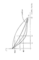
図9は、この一例を示す図である。同図においては、インクデューティ(%)を横軸,明度(L*)を縦軸とし、あるKインクとlcインクとのそれぞれについてインクデューティと明度との相関を示している。インクデューティは印刷媒体に対してインクを打ち込まない場合を0%,許容される最大打ち込み量を打ち込もうとする場合を100%としており、0%は上記KCMYlclmデータの階調値”0”,100%は上記KCMYlclmデータの階調値”256”に対応している。
【0067】
同図においては、上記KCMYlclmデータの各階調値に対応して本実施形態におけるハーフトーン処理を行わずに、インクデューティに対応したインク量での印刷を実行させようとした場合の一般的な相関を示している。従って、特定のデューティにおいて印刷媒体に付着するインクの絶対量や印刷媒体上のインク滴の厳密な位置が図9から特定されるとは限らない。すなわち、あるデューティで印刷を実行しようとしてもノズルの状況や高速印刷等の印刷モード等、種々の条件によって相関は変動し、本発明においては、この相関の変動に応じて濃度パターン法での階調を決定するものである。
【0068】
同図に示すKインクの例では、低デューティから中デューティ域においてデューティの増大とともに明度が急激に低下し、高デューティ域ではデューティの増大に対して明度の低下度合いが鈍くなる。同図に示すlcインクの例では、低デューティ域においてデューティの増大に対する明度の低下度合いが鈍く、中デューティから高デューティ域ではデューティの増大に対する明度の低下度合いが大きい。すなわち、Kインクにおいては、低デューティから中デューティ域での明度変化率が高デューティ域での明度変化率より大きい。また、lcインクにおいては、中デューティから高デューティ域での明度変化率が低デューティ域での明度変化率より大きい。従って、図9におけるKインクの高デューティに対応するサブ画素のインク吐出量変動は冗長(4個のサブ画素についてインク滴の数が多い場合にはその数の変化に応じて明度が明示的に変動しない)であり、図9におけるlcインクの低デューティに対応するサブ画素のインク吐出量変動は冗長である。
【0069】
(2−2)インク吐出量の割り当て:
そこで、Kインクでは低デューティから中デューティ域においてサブ画素のインク滴数の増加率を高デューティ域より小さくする。また、lcインクでは中デューティから高デューティ域においてサブ画素のインク滴数の増加率を低デューティ域より小さくする。さらに、本実施形態においては上記図8に示すようにサブ画素に対して吐出するインクのうちインク滴数が1個〜3個のいずれかを排除し、図8に示す4つのサブ画素にて4階調の表現をすることにしてある。これにより、全4階調を2ビットのデータにすることができる。従って、変換前の上記KCMYlclmデータの1画素について変換後の中間画像データでは2ビットで階調を特定することができる。
【0070】
具体的には、図9に示すようにKインクでは低デューティから中デューティ域にてインク滴数の増加率を小さくするためにインク滴数”0,1,2”を割り当てることになり、高デューティ域ではインク滴の増加率をこれより大きくするためにインク滴数”3”を排除し、インクデューティの増加に伴ってインク滴数が”2”から”4”に変化するように割り当てを行う。一方、lcインクでは図9に示すように中デューティから高デューティ域にてインク滴数の増加率を小さくするためにインク滴数”2,3,4”を割り当てることになり、低デューティ域ではインク滴の増加率をこれより大きくするためにインク滴数”1”を排除し、インクデューティの増加に伴ってインク滴数が”0”から”2”に変化するように割り当てを行う。
【0071】
以上のように各インクデューティに対する割り当てを行うと、上記画像データの各階調値増加に対してKインクではインク滴数が”0,1,2,4”と増加し、lcインクではインク滴が”0,2,3,4”と増加することになるが、両者とも冗長な階調が排除されているのでデータとしては2bitで十分でありながらも、明度の変化ピッチとしても大きなジャンプが無く、情報量の低減と条件変動(この場合はインク色の差異)に的確に対応した階調変化とを両立することができる。むろん、図9に示すKインクとlcインクとは一例であり、相関が上述の相対関係と同様の関係を満たすインクでは同様の考え方で割り当てを決定することができる。
【0072】
ハーフトーン処理モジュール21cは、以上のようにして各色毎に決定された割り当て手法に基づいて各色毎に中間画像データを生成しており、ステップS130にて相関データ42aと相関データ15cとを取得する。これらの相関データは各色インクのインクデューティと明度との相関を示す情報であり、ハーフトーン処理モジュール21cが当該相関データを参照することによってステップS140にて各色毎に割り当て手法を決定する。そして、ステップS150にて各色毎の割り当て手法によって各色毎に疑似中間データを生成する。
【0073】
印刷データ生成モジュール21dはかかる中間画像データを受け取って、ステップS160にてプリンタ40で使用される順番に並べ替える。そして、この並べ替えられたデータを印刷データとして出力する。この結果、プリンタ40にて上記RGBデータ15aに基づく画像が印刷される。尚、データをどの段階でプリンタ40に転送してもよく、上述のように並べ替え後のデータを転送する構成以外にも、色変換後画像データや中間画像データ等、種々の段階で転送することができる。むろん、並べ替え前の段階で転送する際には、プリンタ40側でインク滴の吐出/非吐出を画素毎に決定したデータであって、使用される順番に並べたデータを生成することになる。
【0074】
上記相関データ42a,15cはインクデューティと明度との相関を示す情報であって割り当ての決定に利用することができる限りにおいて種々の態様を採用可能である。例えば、各色インクについてデューティ域を複数の領域に分割して各領域での変化率を示すデータとしておけば、各領域毎に明度の変化率を容易に比較することができる。さらに、相関を予め測定するとともに各インクの相関をフラグで表現するとともに、ハーフトーン処理モジュール21cがこのフラグに基づいて割り当て手法を決定しても良く、他にも種々の態様を採用可能である。
【0075】
上述の具体例では、同一色インクにて異なるインクデューティ域での相対比較を行っていたが、むろん他の視点に基づいて割り当てを決定しても良い。図9の破線は各インクデューティ値にてlcインクの明度値を定数倍することによって規格化し、lcインクの明度域を仮想的にKインクの明度域と合致させた場合を示している。この規格化によって異なる色同士を比較して異なる色のインクについて異なる割り当てを行うことも可能である。
【0076】
同図に示すKインクと破線に示す規格化されたlcインクとで比較すると、低デューティから中デューティ域においてKインクは、インクデューティの増加に伴う明度の低下率がlcインクにおける低下率より大きい。また、中デューティから高デューティ域においてlcインクは、インクデューティの増加に伴う明度の低下率がKインクにおける低下率より大きい。そこで、Kインクの高デューティ域においてインク滴数の増加率を大きくし、lcインクの低デューティ域においてインク滴数の増加率を大きくする。各インクでのデューディ域におけるインク滴数の割り当ては、所望の情報容量に応じて適宜決定すればよい。(本実施形態の場合は、情報量を2bitにするためにインク滴数”0”と”4”の間に2階調与えることができ、例えば、Kインクでは高デューティ域で増加率を大きくしつつ残りの2階調を利用するためにインク滴数”1””2”を採用すればよい。)
【0077】
上記Kインクとlcインクとではインクデューティの増加に対する明度の変化率が他の値域より大きな値域が存在し、値域間での明度変化率の差異に起因して冗長なインク吐出量と非冗長なインク吐出量が存在したが、総ての場合にこのような有意な差が生じるとは限らない。この場合であっても情報量を低減することは可能である。図10は、この例を示しており、KインクとCインクとについてインクデューティと明度との相関を示している。尚、同図横軸と縦軸は上記図9と同様であり、Kインクについては上記図9に示す例と同様である。
【0078】
図10に示すCインクでは、全デューティ域で明度の変化率が急激に変化することなく、略一定の変化率である。従って、サブ画素の階調を表現する際に冗長なインク吐出量は存在しない。そこで、サブ画素の階調を2bitで表現しつつも、特定の階調を示すデータでは2つのインク吐出量のいずれかを意味することとし、図10に示す例では4階調のうち低デューティ側から3番目の階調を示すデータをインク滴数”2””3”のいずれかであるとする。従って、中間画像データを利用する際に上記3番目の階調を示すデータが存在する場合には、インク滴数”2””3”のいずれかに展開すればよい。
【0079】
かかる構成は、中間画像データをプリンタに転送し、プリンタ40側でラスタデータに展開する態様に対して適用すると好ましい。すなわち、かかる態様であれば、印刷時の4画素について2bitの小容量で階調表現した中間画像データを転送すれば良く、少ない情報量のデータ転送を行うことによって、高スループットのシステムを構築することができる。尚、本実施形態におけるハーフトーン処理モジュール21cは、256階調のKCMYlclmデータに基づいてサブ画素のインク滴数を決定するので、上述の例においてインク滴数”2””3”を割り当てるにあたり、インク滴数”2””3”が割り当てられるKCMYlclmデータの階調値域を他のデータ(例えば2番目の階調を示すデータ)より多くすると好ましい。
【0080】
また、2つのインク吐出量のいずれかを意味する階調を2つのインク吐出量に展開する際には、一定の比率でインク滴数”2””3”のいずれかに振り分けても良いし、ディザ法,重み付け演算,乱数等によっていずれかに振り分けても良く、種々の手法を採用可能である。さらに、上述の例ではサブ画素数が4であってので、2つのインク吐出量のいずれかを意味する階調を生成したが、むろん、サブ画素数が増えた場合に2つ以上のインク吐出量のいずれかを意味する階調を生成しても良い。
【0081】
(3)他の実施形態:
本発明においては、条件によって異なるインクデューティと明度との相関に対応させつつハーフトーン処理モジュール21cでの割り当てを実施することができれば良く、上述のように同一色インク内でのデューティ域相関の差異に対応したり、異色インク間の差異に対応する他にも種々の態様を採用可能である。例えば、飛翔インク滴の特性の差異に起因して生ずる相関の差異に対応させることが可能である。
【0082】
図11はインク滴の吐出周波数と吐出インク滴の重量との関係を示している。同図においては、横軸が時間であり縦軸がインク重量である。また、原点Oでのインク重量は上記図4に示す時間Tbでの吐出インク重量である。同図においては上記ピエゾ素子PEを駆動する力が一定であっても周波数がある程度大きくなるとインク重量が変動することを示している。
【0083】
具体的にはプリンタ40においてインク滴を吐出すると、上記図4に示すようにインク面が振動し、図4に示す時間Tb以降ではインク面が安定するので、この時間Tb以降の時間域でインク滴を吐出してもインク重量に変動はないが、時間Tbでインク滴を吐出すると、インク面がノズル開口部より下に位置していることに起因して吐出インク滴重量が増加する。時間Taでのインク滴吐出は、高解像度印刷や高解像度での印刷のようにインク滴吐出周波数が大きくなる場合に発生する。図11の曲線aは、この特性、すなわち、ある周波数以降では周波数の増大とともにインク重量が増大する特性を示している。
【0084】
尚、プリンタ40においては、周波数の増大とともにインク重量が増大するが、ノズル形やピエゾ素子PEの駆動特性によっては、インク滴吐出後のインク面振動の様子が変動し、周波数の増大とともにインク重量が減少する場合もある。図11の曲線cはかかる特性の一例を示している。いずれにしても、インク滴吐出の周波数によって吐出インク滴の重量が変動する場合がある。図12はインク滴の重量変動によるインクデューティと明度との相関の変動を説明する説明図である。横軸と縦軸とは上記図9と同様である。
【0085】
図において曲線bはインク滴の重量変動が無い場合(時間Tb以降でインク滴を吐出した場合)の相関を示しており、曲線a,曲線cは上述の図11と同様にそれぞれ時間Taのいずれかでインク滴を吐出することによってインク滴重量が増大する場合と減少する場合との相関を示している。図に示すように、インク滴重量が増減すると、インクデューティと明度との相関も変動し、同じ色のインクであってもインク滴吐出周波数によって上記ハーフトーン処理モジュール21cでの割り当て手法を変更すべき場合がある。
【0086】
具体的には、図12における曲線aでは低デューティから中デューティ域においてデューティの増大とともに明度が急激に低下し、高デューティ域ではデューティの増大に対して明度の低下度合いが鈍くなる。同図に示す曲線cでは、全デューティ域で明度の変化率が急激に変化することなく、略一定の変化率である。従って、曲線aの高デューティに対応するサブ画素のインク吐出量変動は冗長であり、曲線cサブ画素の階調を表現する際に冗長なインク吐出量は存在しない。
【0087】
そこで、曲線aのような特性である場合には、低デューティから中デューティ域においてサブ画素のインク滴数の増加率を高デューティ域より小さくする。また、曲線cのような特性の場合には、サブ画素の階調を2bitで表現しつつも、特定の階調を示すデータでは2つのインク吐出量のいずれかを意味することにする。この結果、インク重量に起因する相関の変動に的確に対応した階調変化と情報量の低減とを両立することができる。
【0088】
飛翔インク滴の特性としては、他にも種々の特性がある。例えば、インク滴の径を変動可能に構成する場合があり、この場合にもインク滴の径によってインクデューティと明度との相関が変動し、この変動に対応する割り当てを実施可能である。具体的には、上記サブ画素の1つ当たりに大中小いずれかの径のインク滴を吐出可能に構成することによりサブ画素の1つあたりで4階調の表現を行う例が該当する。大中小の径でインクを吐出するためには上記プリンタ40においてピエゾ素子PEに対する印加電圧パターンを変動させることによって実現可能である。
【0089】
図13は、大中小それぞれのインク滴(大中小ドット)において上記KCMYlclmデータの階調値に対して設定されたインクデューティ値の例をインク滴の径毎に示す図である。このように、KCMYlclmデータの低階調値域では主に小ドットを利用し、中階調値域では主に中ドットを利用し、高階調値域では大ドットを利用する。図14は、これら大中小ドットのそれぞれについてのインクデューティと明度との相関を示す図である。
【0090】
同図に示すように、大中小ドットではインクデューティと明度との相関が異なり、この例では小ドットと中ドットは全インクデューティ域に渡ってリニアに明度が変化するが、大ドットは低デューティから中デューティ域においてデューティの増大とともに明度が急激に低下し、高デューティ域ではデューティの増大に対して明度の低下度合いが鈍くなる。そこで、大ドットでは低デューティから中デューティ域においてサブ画素のインク滴数の増加率を高デューティ域より小さくし、小ドットと中ドットではサブ画素の階調を2bitで表現しつつも、特定の階調を示すデータでは2つのインク吐出量のいずれかを意味することにする。この結果、インク重量に起因する相関の変動に的確に対応した階調変化と情報量の低減とを両立することができる。
【0091】
条件によって異なるインクデューティと明度との相関に対応させつつハーフトーン処理モジュール21cでの割り当てを実施する際に、インク滴が印刷媒体上で占める面積を考慮しても良い。図15は印刷媒体上でインク滴が占める面積を説明する説明図である。同図においては、各サブ画素の一つについて大中小の各ドット径のインクを吐出可能な構成にてインクデューティを変化させた場合の面積変化を示している。
【0092】
同図では左から右に向けてインクデューティが増大した状況を示し、上側では小ドットのインク滴による面積,下側では大ドットのインク滴による面積を示している。尚、図における丸は印刷媒体上のインク滴を模式的に示している。図に示す例において、小ドットのインク滴は印刷媒体上で各サブ画素の一つに該当する領域(図15の1マス該当)内に含まれるが、大ドットのインク滴は各サブ画素の一つに該当する領域より大きい。
【0093】
従って、図に示す小ドットと大ドットでは左から右に向けてインク滴数の増加率は同一であるものの印刷媒体上でインクが占める面積の減少率は異なってくる。印刷媒体における明度は、照明および錐体の分光感度による寄与を除いて考えると、単位面積当たりに占めるインクの面積とその分光反射率との積および印刷媒体の露出面積とその分光反射率の積についての波長による積分から特定される。すなわち、インクデューティの増大に伴う明度変化は、インク滴が印刷媒体上で占める面積の増加率に依存性がある。
【0094】
図15の上側に示す小ドットでは、インクデューティの増大に伴ってインク滴同士が重ならないので、インクデューティの増大に伴う印刷媒体の露出面積の変化率は全インクデューティ値域に渡って大きく変動することはない。しかし、大ドットでは隣り合うインク滴同士が重なるので、インクデューティの増大に伴って印刷媒体の露出面積の変化率が変動する。すなわち、インク滴の面積を考慮したときに、小ドットではインクデューティの増大に伴う明度変化率は略一定であるが、大ドットではインクデューティの増大に伴う明度変化は高デューティ側で低下する傾向にある。
【0095】
従って、以上のように印刷媒体上のインク滴の面積に起因して変動するインクデューティと明度との相関に対応させてサブ画素に対するインク吐出量の割り当てを決定しても良い。尚、上述の例では同一径のインク滴について面積の変化率を説明したが、むろん、異なる径のインク滴を印刷媒体上で混在して使用する場合にその面積変化率に起因して変化するインクデューティと明度との相関に対応させても良い。
【0096】
さらに、インク滴の飛翔特性や当該飛翔特性に伴うインク滴付着位置の変動に起因して変動するインクデューティと明度との相関に対応させても良い。図16は、かかる例を示す図である。同図においてはプリンタ40に搭載されたキャリッジ47a1,47a2を示しており、キャリッジ47a1は主走査の往道時,キャリッジ47a2は主走査の復動時である。すなわち、この例は、キャリッジが往復動する際の双方にて印刷を実行する双方向印刷モードである。キャリッジ47a1,47a2から吐出されたインク滴は印刷媒体Pに向けて飛翔する際に慣性によって紙面右側あるいは左側にも移動するが、通常同じ画像データで印刷を実行した際には同じ位置にインク滴を付着させようとしている。
【0097】
しかし、図16に示すように往道と復動で微妙に位置がずれる場合もある。この場合には、インクデューティの増大に伴うインク滴の面積の変化率が往道と復動とで異なる。また、キャリッジの往道と復動のそれぞれにおいて同じ力でインク滴を吐出させたとしてもインク重量が微妙に変動する場合もある。これらの場合、インクデューティと明度との相関が往道と復動とで変動するので、この変動に対応させてサブ画素に対するインク吐出量の割り当てを変動させても良い。
【0098】
以上の実施形態においては、上記プリンタ40のROM42に記憶された相関データ42aやHDD15に記憶された相関データ42aやHDD15cに基づいてインクデューティと明度との相関を把握することによってこれに対応したインク吐出量の割り当てを実現していたが、ユーザーの入力に基づいてインクデューティと明度との相関を示す情報を取得しても良い。かかる構成であれば、プリンタ40の経時変化に対応することができて好適である。
【0099】
この例は、上記第1実施形態のコンピュータ10において所定のキャリブレーションプログラムを起動可能にする構成等によって実現することができる。具体的にはキャリプレーションプログラムによってインクデューティと明度との相関を明らかにする所定のパターンを印刷する。所定のパターン例としてはKインクによるパッチとCMY3色によるコンポジットグレーのパッチとを採用可能である。すなわち、キャリブレーションプログラムによってKインクによるパッチとCMY3色によるパッチとであって製品出荷時に両者が同等の明度になるようなパッチを印刷する。
【0100】
図17にはプリンタ40の出荷時でのKインクによるパッチとコンポジットグレーによるパッチのインクデューティに対する明度変化を示している。同図においては、横軸にインクデューティを示し、縦軸に明度を示しており、Kインクについては上記図9と同様であるが、コンポジットグレーにおいては、3色合わせた状態でのインクデューティを規定してグラフにプロットしている。図17に示すように、低デューティ域でのデューティ増加に伴う明度変化はKインクの方が急激であり、コンポジットグレーでは全デューティ域に渡って略一定の明度変化率である。
【0101】
上記キャリブレーションプログラムにて印刷するパッチの明度がL0のとき、同図に示すようにKインクでのパッチをデューティK1で印刷し、コンポジットグレーでのパッチをデューティK2で印刷することになる。プリンタ40の出荷時に、デューティK1でのKインクのパッチと、デューティK2でのコンポジットグレーのパッチが同明度L0であったとしても、経時変化によってインク吐出特性が変動すると、各パッチの明度が変動し得る。
【0102】
コンポジットグレーはCMY3色の組み合わせであることからいずれかのインクの吐出特性変動等によって明度が変動しやすい。そこで、コンポジットグレーにおいてインクデューティと明度との相関が変動した場合について説明する。インクの吐出特性変動等によって上記相関は図17の一点鎖線や破線のように変動する。一点鎖線の場合はデューティK2で印刷したパッチであっても明度が上昇し、破線の場合は低下する。
【0103】
そこで、上記コンピュータ10にてコンポジットグレーのパッチがKインクのパッチより暗い/明るいのいずれかを選択するためのUIを表示し、上記キーボード31やマウス32等の入力機器を介して利用者に暗い/明るいのいずれかを選択させる。そして、利用者が「暗い」を選択したときにはインクデューティと明度との相関が上記図17に示す破線のようになっているとし、上記ハーフトーン処理モジュール21cにて中間画像データを生成するときに低デューティから中デューティ域でインク吐出量変動率が小さくなるようにインク吐出量の割り当てを実施する。
【0104】
利用者が「明るい」を選択したときにはインクデューティと明度との相関が上記図17に示す一点鎖線のようになっているとし、上記ハーフトーン処理モジュール21cにて中間画像データを生成するときに高デューティ域でインク吐出量変動率が小さくなるようにインク吐出量の割り当てを実施する。この結果、プリンタ40におけるインク吐出特性の経時変化に対応したインク吐出量の割り当てを実施することが可能になる。以上説明したように、本発明によれば、濃度パターン法によってハーフトーン処理を実施する際に、種々の条件によって変動するインクデューティと明度との相関に対応させながらインク吐出量の割り当てを行うことができ、情報量の低減と条件変動に的確に対応した階調変化とを両立させることができる。
【図面の簡単な説明】
【図1】印刷制御装置を構成するシステムの概略ハードウェア構成を示す図である。
【図2】プリンタの概略ハードウェア構成を示す図である。
【図3】ノズルおよびその内部構造を拡大して示す図である。
【図4】インク面が振動する状態を示す図である。
【図5】印刷装置の主な制御系の概略構成図を示す図である。
【図6】データ処理の流れを示す説明図である。
【図7】印刷制御処理のフローチャートである。
【図8】ハーフトーン処理を説明する説明図である。
【図9】インクデューティと明度との相関の例を示す図である。
【図10】インクデューティと明度との相関の例を示す図である。
【図11】インク滴の吐出周波数と吐出インク滴の重量との関係を示す図である。
【図12】インク滴の重量変動によるインクデューティと明度との相関の変動を説明する説明図である。
【図13】大中小のインク滴を使用する場合のインクデューティ値の例を示す図である。
【図14】大中小ドットのそれぞれについてのインクデューティと明度との相関を示す図である。
【図15】印刷媒体上でインク滴が占める面積を説明する説明図である。
【図16】双方向印刷時のキャリッジを示す説明図である。
【図17】Kインクによるパッチとコンポジットグレーによるパッチのインクデューティに対する明度変化を示す図である。
【符号の説明】
10…コンピュータ
11…CPU
12…システムバス
13…ROM
14…RAM
15…ハードディスクドライブ(HDD)
15a…RGBデータ
15b…LUT
15c,42a…相関データ
16…フレキシブルディスクドライブ
17…CD−ROMドライブ
18…ディスプレイ
20…OS
21…プリンタドライバ(PRTDRV)
21a…画像データ取得モジュール
21b…色変換モジュール
21c…ハーフトーン処理モジュール
21d…印刷データ生成モジュール
22…入力機器ドライバ(DRV)
23…ディスプレイドライバ(DRV)
25…アプリケーションプログラム(APL)
31…キーボード
32…マウス
40…プリンタ
41…CPU
42…ROM
43…RAM
44…ASIC
45…コントロールIC
47a…キャリッジ機構
47b…紙送り機構
48a〜48f…インクカートリッジ
48g…インク室
49…ヘッド駆動部[0001]
TECHNICAL FIELD OF THE INVENTION
The present invention relates to a print control device, a print control program, and a print control method.
[0002]
[Prior art]
In recent years, as the performance of ink jet printers has been improved, demands for higher speed and higher resolution have been increasing. In order to realize printing at a high resolution, processing for a large number of pixels is generally required, and the computational load of the processing increases. For example, the print control device interpolates and enlarges the pixels so as to have the number of pixels for printing the original image at the target print resolution, executes color conversion processing and halftone processing, and performs ink discharge / Print data that defines non-ejection is generated. Since printing at a high resolution requires many pixels, if the number of pixels at the time of printing and the number of pixels at the time of performing the color conversion processing are equal, the processing load is extremely large, and the processing takes time. .
[0003]
Therefore, as one answer for speeding up, the conventional print control apparatus sometimes uses the density pattern method for halftone processing. In the density pattern method, for example, one pixel expressed in multiple gradations corresponds to n × n (n is a natural number of 2 or more) sub-pixels, and each sub-pixel has a binary gradation (ink ejection). / Binary by non-ejection), the gradation is expressed by the number of ink droplets in n × n pixels. Therefore, if the above-described color conversion is performed with pixels smaller than the printing resolution and pixels formed by the density pattern method at the time of printing are configured, the number of pixels of image data handled in an intermediate stage can be suppressed, and the processing load is reduced. Become smaller. In addition, by appropriately adjusting the number of gradations represented by the plurality of sub-pixels corresponding to the one pixel, the number of bits required to specify the gradation of the sub-pixel can be adjusted.
[0004]
[Problems to be solved by the invention]
In the above-described conventional print control apparatus, it has not been possible to achieve both a reduction in the amount of information and a gradation change accurately corresponding to a condition change. In other words, the larger the number of ink droplet patterns assigned to the n × n sub-pixels, the more gradations can be expressed, but if the number of gradations is large, the number of bits increases. Even if a pattern of a specific number of ink droplets is excluded in order to reduce the number of bits, it is not possible to appropriately cope with each condition because the ink ejection characteristics differ depending on the ink color and nozzle. Therefore, even if the optimum gradation change can be expressed by specific conditions such as the color of a specific ink, the optimum gradation change cannot be expressed with the minimum necessary information amount for all conditions. .
The present invention has been made in view of the above problems, and provides a print control apparatus, a print control program, and a print control method capable of achieving both a reduction in the amount of information and a gradation change that accurately corresponds to a condition change. With the goal.
[0005]
Means for Solving the Problems and Effects of the Invention
In order to achieve the above object, in the invention according to the first aspect, the density for converting multi-tone data of one pixel into intermediate image data of more sub-pixels and less gradation expression per unit pixel. When performing printing by executing the pattern method, it is necessary to select a density pattern such that the gradation of the sub-pixel is accurately changed according to the ink duty / color value characteristics while effectively reducing the information amount. it can. That is, since the density pattern method is used, the original gradation of one pixel can be expressed as a gradation of a plurality of sub-pixels. For this reason, the number of pixels for realizing the printing resolution can be set at the stage where the number of pixels is increased at the time of conversion to the intermediate image data, and the number of pixels of the image data to be converted to the intermediate image data is determined as the printing resolution. Can be smaller than the number of pixels for realizing Therefore, printing can be performed with a small amount of information.
[0006]
Further, when assigning the ink ejection amount by the density pattern method, the assignment of the redundant ink ejection amount is prevented by making the pitch of the gradation expressed by the sub-pixel non-uniform. Therefore, it is not necessary to spend information capacity for the excluded ink ejection amount, and the gradation of the sub-pixel can be expressed with a small information amount. In the present invention, a redundant ink discharge amount is excluded, not a specific ink discharge amount for a sub-pixel. That is, even if the ink ejection amount is eliminated, an ink ejection amount that does not cause a large jump in the color value change pitch with respect to an increase in the ink duty is eliminated, and the color value change pitch is made as constant as possible.
[0007]
That is, the correlation between the ink duty and its color value differs depending on the color of the ink, the ink ejection timing, the printing speed, the printing mode, and the like, and the color value on the printing medium changes linearly with a linear increase in the ink duty. May not change.
[0008]
For example, when the ink duty is increased to some extent, the rate of decrease in the color value is sharply reduced, or when the ink duty is small, the rate of decrease in the color value is small with respect to the increase in the duty. There are various cases such as a case where the temperature decreases. As described above, when the decrease rate of the color value is small with respect to the increase in the duty, even if the ink discharge amount for the sub-pixel is finely changed, the change in the effective brightness or the change in the saturation is small. Even though many gradation changes are possible in this situation, it is redundant.
[0009]
Therefore, if such a redundant ink ejection amount is eliminated, the amount of information can be reduced while maintaining the constantness of these changes without giving a large jump to the degree of change in color value. Further, the correlation between the ink duty and the color value may vary depending on the ink color and printing conditions. However, in the configuration for eliminating the redundant ink ejection amount and maintaining the uniformity of the color value, the ink color and the printing Since the assignment of the ink ejection amount can be changed in accordance with the difference for each condition, it is possible to achieve both a reduction in the amount of information and a gradation change that appropriately corresponds to the condition change.
[0010]
Here, the ink duty is an index for specifying the amount of ink to be ejected per unit area, and the entire value range is from the situation where the ink is not ejected to the situation where the ink is ejected to the limit, and the ink duty is defined for each ink color. ing. In this specification, the duty of each color ink is defined as the ink duty, and even if the ink duty value is the same, the ink ejection amount is not necessarily the same for each ink color. In addition, although the amount of ink to be ejected can be determined at each ink duty value, the amount of ink actually ejected may vary depending on conditions such as the above-described ejection timing, even if the target ejection amount is constant. .
[0011]
The image data only needs to express the color of each pixel in multiple gradations. Normally, the image data is color image data having a plurality of color components per pixel, but, of course, monochrome image data using only brightness information is used. There may be. Although the color component is not particularly limited, in view of performing printing with the ink ejection amount specified by the intermediate image data, image data having a color component corresponding to the ink color mounted on the printing apparatus is used. Preferably, there is. Of course, the number of color components is not particularly limited, and various color numbers such as four colors, six colors, and seven colors can be adopted.
[0012]
The number of sub-pixels is not particularly limited. That is, it is only necessary to have two or more pixels. Note that, in order to keep the aspect ratio of the image from changing during the conversion to the intermediate image data, the number of vertical sub pixels x the number of vertical pixels of the intermediate image is the number of recording pixels in the vertical direction, and the number of horizontal sub pixels x intermediate It is preferable that the number of horizontal pixels of the image is the number of recording pixels in the horizontal direction. Various gradation expressions can be adopted as the gradation expression in the sub-pixel. For example, a configuration in which two gradations are provided for one sub-pixel in a state where ink is ejected and a state in which ink is not ejected may be used. Alternatively, the configuration may be such that the diameter of the ink droplet is adjustable between large, medium, and small so as to provide four gradations for one of the sub-pixels, and various configurations may be employed.
[0013]
In the intermediate image data, it is sufficient that the ink ejection amount can be specified for each of the sub-pixels. Needless to say, processing for rearranging the pixels in the ink ejection order may be added. Further, in the present specification, the assignment is determined to determine the amount of ink to be ejected to all of the plurality of sub-pixels, and the number of ink droplets in the entire sub-pixel and the ink to be ejected to each sub-pixel are determined. Determining the size of a drop or the like corresponds to the assignment determination. The color value in the present invention is an index for evaluating the color of the print result by the quantity when printing is performed with each ink duty value, and the color value is lightness as in the invention according to claim 2. Or good saturation. That is, the lightness and saturation vary depending on the amount of ink recorded per unit area, and when the dark and light ink droplets are properly used, the light and dark of the ink droplets themselves are different even if they are the same amount. Its lightness and saturation vary depending on the state. Therefore, the assignment of the ink ejection amount to the sub-pixel may be determined according to the correlation between these color values and the ink duty.
[0014]
Various methods can be adopted as a method of maintaining the uniformity of the color value change pitch while eliminating the redundant ink ejection amount, and as an example of the configuration, in the invention according to claim 3, the ink duty and In considering the correlation with the color value, the correlation is relatively compared for each ink duty value range so that the ink amount change rate is small in the ink duty value range where the color value change rate is large. That is, the ink ejection amount redundant with respect to the color value change is a situation in which the effective color value change is small even if the ink ejection amount is finely changed as described above. Therefore, if the change in the ink amount is fine in the ink duty value range where the color value change rate is large, the gradation can be accurately expressed in the ink duty value range where a fine gradation is required.
[0015]
Even if redundant ink ejection amounts are eliminated, it may be difficult to determine which ink ejection amount is redundant. In such a case, it is possible to increase the number of tones again in the printing apparatus that actually performs printing while eliminating the tones at any of the ink discharge amounts. For example, the intermediate image data from which the redundant ink ejection amount has been eliminated may be transferred to the printing apparatus, and the ink ejection amount eliminated by the dither method, weighting operation, random number, or the like may be reproduced on the printing apparatus side. Such a configuration is suitable for a case where the change rate of the color value with the increase of the ink duty is small, that is, when the correlation between the ink duty and the color value is linear, and it is difficult to clearly specify the gradation to be excluded. It is particularly suitable when applied.
[0016]
Further, in the invention according to claim 4, as a configuration example of a method for maintaining the uniformity of the color value change pitch while eliminating a redundant ink ejection amount, the method according to the present invention considers the correlation between the ink duty and the color value in each ink. However, the correlation is relatively compared between different inks, and the assignment method is changed between inks having different correlations. Therefore, it is possible to determine the assignment method accurately in response to each of various situations that differ depending on the color of the ink, the ink ejection timing, the printing speed, the printing mode, and the like. Intermediate image data appropriately corresponding to the correlation of each ink can be generated with the number of gradations.
[0017]
Further, in the invention according to
[0018]
When such standardization is considered, it can be said that an ink having a standardized color value decrease rate smaller than other inks with an increase in ink duty has greater redundancy than the other inks. Therefore, by increasing the increase rate of the ink ejection amount with the increase in the gradation value of each pixel in the image data as compared with the other inks, it is possible to eliminate redundant gradations and reduce the information amount. In most cases, the correlation between the change rate of the ink duty and the change rate of the standardized color value is not substantially constant over the entire ink duty value range. It is not necessary to satisfy the above-described relative relationship over a period of time, and the present invention can be applied to the case where the above-described relative relationship is satisfied in some ink duty value ranges.
[0019]
According to the above-described assignment of the ink ejection amount, when the halftone processing unit assigns the ink ejection amount to each of the sub-pixels, the rate of decrease in the standardized color value due to the increase in the ink duty is reduced by another ink. With respect to the ink having a larger decrease rate in the above, the increase rate of the ink ejection amount with the increase in the gradation value of each pixel in the image data can be made smaller than that of the other inks. Therefore, it is possible to realize an appropriate gradation change in a value range where a small change in the ink ejection amount is required.
[0020]
Further, when allocating the ink ejection amount to each sub-pixel, the ink in which the standardized color value decrease rate with the increase of the ink duty is an intermediate value of the decrease rates of the other two inks is the above-described ink. A configuration may be adopted in which the increase rate of the ink ejection amount due to the increase in the gradation value of each pixel in the image data is an intermediate value between the other two inks. That is, as described above, when determining the assignment of the ink ejection amount to the sub-pixels in accordance with the rate of decrease in the color value due to the increase in the ink duty, removing the redundant gradation reduces the information amount. In some cases, it is not clear which of the two gradations the ink ejection amount should be excluded depending on the correlation between the color and the color value.
[0021]
In such a case, it is possible to increase the gradation again in the printing apparatus that actually performs printing while eliminating the gradation at any of the ink discharge amounts. For example, the intermediate image data whose information amount is reduced by eliminating the redundant ink ejection amount is transferred to the printing device, and the ink ejection amount eliminated by the dithering method, the weighting operation, the random number, or the like is reproduced on the printing device side. Just fine. This configuration is particularly suitable when applied to a situation where the change rate of the color value with an increase in the ink duty is small, that is, the change rate is linear, and it is difficult to clearly specify the ink ejection amount to be eliminated. It is.
[0022]
In the invention according to claim 6, resolution conversion processing, color conversion processing, and halftone processing can be performed on the original image data, and the number of pixels at the printing resolution is determined by sub-pixels generated by the halftone processing. . In halftone processing, data of one pixel is converted into data composed of more sub-pixels, so in color conversion processing before halftone processing, processing with a smaller number of pixels may be performed, and processing load is reduced. High-speed printing is possible. In a large-format printing device that executes printing at a high resolution or has a large number of pixels, such as a printing device in recent years, such a reduction in processing load greatly contributes to an increase in printing speed.
[0023]
Here, the resolution conversion unit only needs to be able to enlarge and reduce the image data. That is, if the number of target pixels of the halftone processing is larger than the number of pixels of the original input image data, the enlargement processing may be performed, and if the number of target pixels of the halftone processing is smaller than the number of pixels of the original input image data, the reduction processing is performed. Should be performed. The enlargement / reduction algorithm is not particularly limited, and various interpolation calculations and the like can be adopted. The color conversion unit only needs to be able to convert the color components constituting each pixel of the image data into image data represented by ink color components used in the printing apparatus, and the algorithm is not limited here. Of course, in the case where the print control device obtains multi-gradation data based on ink colors and performs processing, the processing by the color conversion unit is unnecessary.
[0024]
In the invention according to claim 7 as a configuration example for reliably reducing the information amount, the number of gradations represented by the sub-pixel is set to 2 n There are as individual. That is, when eliminating the redundant gradation by making the change pitch of the ink ejection amount non-constant, if the number of gradations expressed by the sub-pixel is n bits, the gradation expression is performed by eliminating the redundant gradation. Is reduced from (n + 1) bits or more to n bits. Therefore, the gradation of the entire sub-pixel can be specified with a small number of bits, and the intermediate image data can be formed with a small capacity. n is particularly preferably a natural number of 2 or more.
[0025]
According to the present invention, redundant gradations can be eliminated according to the difference in the correlation between the ink duty and the color value, and various viewpoints can be adopted as the difference in the correlation. For example, as in the invention described in claim 8, inks having different colors can be adopted as inks having different correlations. In other words, the correlation between the ink duty and the color value is different for different colors, such as the darkness of black ink and the like. By determining the intermediate image data by the assignment of (i), it is possible to generate intermediate image data having an appropriate ink ejection amount for each ink color.
[0026]
Further, as in the ninth aspect of the present invention, it is possible to employ inks having different characteristics of ink droplets flying from the nozzles as inks having different correlations. That is, even if ink is to be ejected at the same duty, the characteristics of the ink droplets flying from each nozzle are different, so that the amount of ink actually ejected may be different. As a result, the correlation between the ink duty and the color value varies depending on the characteristics of the ink droplet. Therefore, by determining the gradation of the intermediate image data according to the correlation, it is possible to generate intermediate image data having an appropriate ink ejection amount for each ink color.
[0027]
There are various factors that determine the characteristics of the ink droplet, and any of these factors can be considered as a correlation. Specifically, even if the force for discharging the ink from the ink chamber is constant, the amount of ink discharged when the ink surface is vibrating and the amount of ink discharged when the ink surface is stable are different. Since the amounts differ, a correlation reflecting such an ink amount variation due to the stability of the ink surface may be added. Also, a predetermined time is required until the ink surface becomes stable after the ink droplet is ejected, but when the next ink is ejected without securing this time sufficiently, for example, high-speed printing or high-resolution printing In some cases, even when the ink surface is unstable, the ink amount may be ejected.
[0028]
In general, a printing apparatus ejects ink droplets from a plurality of nozzles. However, the amount of ejected ink and the flying direction may be different due to an assembling error of each nozzle. May be added. Further, the correlation may differ depending on the print mode. For example, the correlation is different between a bidirectional printing mode (a mode in which ink is ejected in both reciprocating motions of the head) and a unidirectional printing mode. Needless to say, the correlation between the ink duty and the color value differs depending on the printing medium, so that a different correlation may be added depending on the printing medium.
[0029]
Further, as in the tenth aspect of the present invention, inks having different amounts of ink per unit number of ejections can be employed as inks having different correlations. In other words, when the diameters of the ejected inks are different, even if the values of the ink duties are the same, the areas occupied by the inks on the printing medium are different, so that the color values are different. Therefore, by determining the gradation of the intermediate image data according to the correlation, it is possible to generate intermediate image data having an appropriate ink ejection amount for each ink color. As described above, since the correlation between the ink duty and the color value is different when the amount of ink deposited per unit area on the print medium is different, the invention according to claim 11 can be employed.
[0030]
In the present invention, in order to allocate the ink ejection amount corresponding to the correlation between the ink duty and the color value, the allocation may be performed according to a predetermined rule, or the information indicating the correlation may be obtained by acquiring the information indicating the correlation. May be performed while referring to. In the former case, for example, the correlation differs depending on the color of the ink, and when the correlation is clear, it is possible to cope with the problem by, for example, creating an assignment algorithm in consideration of the correlation.
[0031]
Various configurations can be adopted as a configuration for realizing the latter, but as an example, as in the invention according to
[0032]
The information indicating the correlation is stored in a predetermined storage medium, and it is sufficient that the information can be acquired. The storage medium may be provided in the printing apparatus, or may be printed when the printing apparatus and the print control apparatus are separate. It may be provided on the control device side. Of course, the computer may be provided in a computer other than the printing apparatus and the print control apparatus when performing the distributed processing. When using the storage medium provided in the printing apparatus, it is preferable to write the information indicating the correlation when manufacturing the printing apparatus in a factory. When a storage medium provided in a computer serving as a print control device is used, when the computer is set up to be usable as a print control device (for example, when a print control program is installed), the data is written to a hard disk drive of the computer. A configuration or the like can be adopted.
[0033]
Furthermore, it is also possible to configure so as to be able to correspond to the correlation input by the user. As a specific example of such a configuration, a predetermined pattern is printed for each ink by the pattern print control unit as in the invention according to
[0034]
Further, in the present invention, it is possible to achieve both a reduction in the amount of information and a gradation change accurately corresponding to a condition change, and the configuration according to
[0035]
With such a configuration, it is possible to perform conversion that accurately corresponds to the correlation between the ink duty and the color value while eliminating redundant gradation. Therefore, it is possible to achieve both a reduction in the amount of information and a gradation change appropriately corresponding to the condition change. Further, the print data generation means only needs to be able to generate data for executing printing with the ink ejection amount specified by the pseudo intermediate data, and may add various processes such as appropriately performing rasterization according to the print mode or the like. Is possible. Of course, in such a configuration, a configuration similar to the above-described claims 2 to 13 can also be adopted.
[0036]
The concept of the present invention is not limited to this, and may include various aspects. For example, the print control apparatus according to the present invention may exist alone or may be used while being incorporated in a certain device. Therefore, it can be changed as appropriate, such as software or hardware. When software for controlling the print control device is used as an embodiment of the idea of the present invention, the software naturally exists and is used on a recording medium on which such software is recorded. To establish. For this reason, the invention according to
[0037]
Of course, the recording medium of this program may be a magnetic recording medium, a magneto-optical recording medium, or any recording medium to be developed in the future. Further, the duplication stages of the primary duplicated product, the secondary duplicated product and the like are equivalent without any question. Although different from the above-described medium, if the supply is performed using a communication line, the communication line is used as a transmission medium and the present invention is used. Further, even when a part is implemented by software and a part is implemented by hardware, the concept of the present invention is not completely different, and a part is stored on a recording medium and appropriately It may be in a form that can be read.
[0038]
In controlling such a printing control apparatus, it is natural that an invention exists in the procedure at the base of each unit performing a process according to a predetermined control procedure. It is possible. For this reason, the invention according to
[0039]
BEST MODE FOR CARRYING OUT THE INVENTION
Here, embodiments of the present invention will be described in the following order.
(1) Configuration of the present invention:
(2) Print control processing:
(2-1) Halftone processing:
(2-2) Assignment of ink ejection amount:
(3) Other embodiments:
[0040]
(1) Configuration of the present invention:
FIG. 1 shows a schematic hardware configuration of a system constituting a print control apparatus according to the present invention, and FIG. 2 shows a schematic hardware configuration of a printer. The
[0041]
In the present embodiment, the
[0042]
Operation input devices such as a
[0043]
In this example, the programs are stored in the
[0044]
On the other hand, as shown in FIG. 2, a
[0045]
The
[0046]
In the ink discharge section of the print head, six sets of nozzle rows for discharging each of the six colors of ink are formed so as to be arranged in the main scanning direction of the print head, and in each of the nozzle rows, a plurality of nozzles are arranged in the sub-scanning direction. They are arranged at regular intervals. FIG. 3 is an enlarged view showing the nozzle and its internal structure. As shown in the figure, the ink in the
[0047]
The piezo element PE expands / contracts according to the applied voltage generated by the
[0048]
FIG. 4 is a diagram showing this state. In the figure, the horizontal axis represents time, and the vertical axis represents the displacement of the ink surface. The origin on the horizontal axis is the time at which voltage application to the piezo element PE is started, and the origin on the vertical axis indicates the position of the ink surface in the stable state. That is, when the ink level is lower than the lower surface of the head over time, the ink is displaced in the negative direction of the vertical axis, and when the ink level is higher than the lower surface of the head, the ink is displaced in the positive direction of the vertical axis. Since the ink surface is stable at the time Tb shown in the figure, even if the ink droplet Ip is continuously ejected in the main scanning direction, the next ink droplet Ip is ejected after reaching the time Tb. In this case, the ejection amount of the ink droplet Ip is stabilized.
[0049]
However, in order to use only this stable state, it is necessary to wait for the time Tb after discharging one ink droplet Ip until discharging the next ink droplet. In order to achieve high-speed printing, it is preferable that the standby time be as short as possible when continuously discharging ink droplets. Further, in order to realize high-resolution printing, the number of times ink is ejected per main scan increases, so that if the standby time is kept constant, the printing speed is reduced accordingly. Therefore, in the present embodiment, the ink droplets are not ejected only after the time Tb, but are ejected at the time Ta as necessary by setting the resolution and the printing speed.
[0050]
When the ink droplet is ejected at the time Ta, the ejection amount fluctuates compared to the ink droplet at the time Tb due to the unstable ink surface (the ink amount fluctuates depending on the ink ejection timing). That is, in the
[0051]
As the
[0052]
In FIG. 2, a
[0053]
FIG. 5 is a schematic configuration diagram of a main control system of the printing apparatus realized by the
[0054]
The
[0055]
That is, the LUT 15b is a table that defines the correspondence between the RGB data and the KCMYlclm data, and defines a combination of each color gradation value of the RGB data and the KCMYlclm data for a predetermined number of reference points. For example, for RGB data, a reference value is formed by dividing a gradation value range of 256 gradations into 16 for each of the RGB element colors, and a gradation value of “0, 16, 32,. The reference point is defined by specifying all combinations.
[0056]
At the time of color conversion, the color conversion module 21b performs an interpolation operation with reference to each reference point, develops the data into an intermediate table having a larger number of reference points, and performs the above-described RGB data by the interpolation operation with reference to the reference points of the intermediate table. The RGB data is converted into KCMYlclm data for each
[0057]
When the color conversion module 21b performs the color conversion, the image is data expressing color components in 256 gradations for each color of KCMYlclm for each dot. In the
[0058]
In the present embodiment, the correlation data indicating the correlation is also stored in the
[0059]
After the halftone process, the print
[0060]
(2) Print control processing:
With the above configuration, the
[0061]
When the user instructs the
[0062]
That is, when printing is performed by the
[0063]
When the resolution conversion processing is performed, the image data acquisition module 21a activates the color conversion module 21b. The color conversion module 21b acquires the LUT 15b stored in the
[0064]
(2-1) Halftone processing:
Next, in steps S130 to S150, the
[0065]
That is, if the difference due to the positions where the ink droplets are attached is not taken into consideration, five gradations can be expressed by the presence / absence of ink droplets depending on the number of ink droplets as shown in FIG. If five gradations are expressed by a binary number, three bits are required. If three bits are used, eight gradations can be expressed. However, it is wasteful to express five gradations with the sub-pixels shown in FIG. Information capacity. Further, as a correlation between the ink duty and the lightness, the lightness often does not linearly increase with respect to the linear increase of the ink duty, and one of the five gradations may be a redundant gradation.
[0066]
FIG. 9 is a diagram illustrating this example. In the figure, the horizontal axis represents the ink duty (%), and the lightness (L) * ) Is the vertical axis, and shows the correlation between the ink duty and the brightness for each of a certain K ink and lc ink. The ink duty is 0% when no ink is applied to the print medium, and 100% when the maximum allowable amount is applied. 0% is the gradation value “0” of the KCMYlclm data. 100% corresponds to the gradation value "256" of the KCMYlclm data.
[0067]
In the same figure, there is a general correlation in a case where printing with an ink amount corresponding to the ink duty is executed without performing the halftone processing in the present embodiment corresponding to each gradation value of the KCMYlclm data. Is shown. Therefore, the absolute amount of ink adhering to the print medium or the exact position of the ink droplet on the print medium at a specific duty is not always specified from FIG. That is, even if an attempt is made to execute printing at a certain duty, the correlation fluctuates depending on various conditions, such as the state of the nozzles and the printing mode such as high-speed printing. The key is determined.
[0068]
In the example of the K ink shown in the figure, the brightness sharply decreases with an increase in the duty in the low to medium duty range, and the degree of decrease in the brightness decreases with an increase in the duty in the high duty range. In the example of the lc ink shown in the figure, the degree of decrease in lightness with respect to an increase in duty is low in a low duty range, and the degree of decrease in lightness with respect to an increase in duty is large in a range from a medium duty to a high duty. That is, in the K ink, the lightness change rate in the low to medium duty range is larger than the lightness change rate in the high duty range. In the case of the lc ink, the brightness change rate in the medium to high duty range is larger than the brightness change rate in the low duty range. Accordingly, the variation in the ink ejection amount of the sub-pixel corresponding to the high duty of the K ink in FIG. 9 is redundant (when the number of ink droplets is large for four sub-pixels, the brightness is explicitly changed according to the change in the number). The variation in the ink ejection amount of the sub-pixel corresponding to the low duty of the lc ink in FIG. 9 is redundant.
[0069]
(2-2) Assignment of ink ejection amount:
Therefore, in the case of the K ink, the rate of increase in the number of ink droplets of the sub-pixels in the low to medium duty range is smaller than that in the high duty range. In the case of the lc ink, the rate of increase in the number of ink droplets of the sub-pixel in the middle to high duty range is smaller than that in the low duty range. Further, in the present embodiment, as shown in FIG. 8 described above, any one of one to three ink droplets is excluded from the ink ejected to the sub-pixel, and the four sub-pixels shown in FIG. It is intended to represent four gradations. Thereby, all four gradations can be converted into 2-bit data. Therefore, for one pixel of the KCMYlclm data before the conversion, the gradation can be specified by 2 bits in the intermediate image data after the conversion.
[0070]
Specifically, as shown in FIG. 9, in the case of the K ink, the number of ink droplets "0, 1, 2" is allocated in order to reduce the rate of increase in the number of ink droplets in the low to medium duty range. In the duty range, the number of ink drops "3" is eliminated in order to increase the rate of increase of ink drops, and the assignment is made so that the number of ink drops changes from "2" to "4" as the ink duty increases. Do. On the other hand, in the case of the lc ink, as shown in FIG. 9, the number of ink droplets “2, 3, 4” is allocated in order to reduce the rate of increase in the number of ink droplets in the medium to high duty range. In order to increase the rate of increase of ink drops, the number of ink drops "1" is excluded, and allocation is performed so that the number of ink drops changes from "0" to "2" as the ink duty increases.
[0071]
When the assignment is made for each ink duty as described above, the number of ink drops increases to "0, 1, 2, 4" for the K ink and increases for the lc ink for each increase in the gradation value of the image data. "0, 2, 3, 4" is increased, but in both cases, since redundant gradations are eliminated, 2 bits are sufficient as data, but there is no large jump in brightness change pitch. In addition, it is possible to achieve both a reduction in the amount of information and a gradation change that accurately corresponds to a condition change (in this case, a difference in ink color). Needless to say, the K ink and the lc ink shown in FIG. 9 are merely examples, and the assignment can be determined based on the same concept in the case of ink whose correlation satisfies the same relationship as the above-described relative relationship.
[0072]
The
[0073]
The print
[0074]
The
[0075]
In the specific example described above, the relative comparison is performed with the same color ink in different ink duty ranges. However, the allocation may be determined based on another viewpoint. The broken line in FIG. 9 indicates a case where the brightness value of the lc ink is normalized by multiplying the brightness value of the lc ink by a constant at each ink duty value, and the brightness range of the lc ink is virtually matched with the brightness range of the K ink. By this standardization, different colors can be compared and different assignments can be made for inks of different colors.
[0076]
Comparing the K ink shown in the figure with the standardized lc ink shown by the broken line, the K ink has a lower rate of lightness increase with increasing ink duty than the lc ink in the low to medium duty range. . Further, in the lc ink in the range from the medium duty to the high duty, the decrease rate of the brightness of the lc ink with the increase of the ink duty is larger than that of the K ink. Therefore, the rate of increase in the number of ink drops is increased in the high duty range of K ink, and the rate of increase in the number of ink drops is increased in the low duty range of lc ink. The assignment of the number of ink droplets in the duty region for each ink may be appropriately determined according to a desired information capacity. (In the case of the present embodiment, two gradations can be given between the number of ink droplets “0” and “4” in order to make the information amount 2 bits. For example, in the case of K ink, the increase rate is large in a high duty range. In order to use the remaining two gradations, the number of ink droplets “1” and “2” may be employed.)
[0077]
In the K ink and the lc ink, there is a value range in which the brightness change rate with respect to an increase in the ink duty is larger than other value ranges, and a redundant ink ejection amount and a non-redundant Although there was an ink ejection amount, such a significant difference does not always occur in all cases. Even in this case, it is possible to reduce the amount of information. FIG. 10 shows this example, and shows the correlation between the ink duty and the brightness for the K ink and the C ink. The horizontal axis and the vertical axis in FIG. 9 are the same as those in FIG. 9, and the K ink is the same as in the example shown in FIG.
[0078]
In the C ink shown in FIG. 10, the change rate of the lightness does not change abruptly in the entire duty range, and is a substantially constant change rate. Therefore, there is no redundant ink ejection amount when expressing the gradation of the sub-pixel. Therefore, while the gradation of the sub-pixel is expressed by 2 bits, data indicating a specific gradation means one of two ink ejection amounts. In the example shown in FIG. It is assumed that the data indicating the third gradation from the side is one of the ink droplet numbers “2” and “3”. Therefore, if there is data indicating the third gradation when using the intermediate image data, the data may be expanded to one of the ink droplet numbers “2” and “3”.
[0079]
Such a configuration is preferably applied to a mode in which intermediate image data is transferred to a printer and rasterized on the
[0080]
Further, when developing a gradation meaning one of the two ink ejection amounts into two ink ejection amounts, the gradation may be distributed to any one of the ink droplet numbers “2” and “3” at a fixed ratio. , A dither method, a weighting operation, a random number, or the like, and various methods can be adopted. Further, in the above-described example, the number of sub-pixels is four, so that a gradation meaning any one of two ink discharge amounts is generated. However, if the number of sub-pixels increases, A gradation representing any of the quantities may be generated.
[0081]
(3) Other embodiments:
In the present invention, it is sufficient that the assignment in the
[0082]
FIG. 11 shows the relationship between the ejection frequency of the ink droplet and the weight of the ejected ink droplet. In the figure, the horizontal axis is time and the vertical axis is ink weight. The weight of the ink at the origin O is the weight of the ejected ink at the time Tb shown in FIG. The figure shows that even when the driving force for the piezo element PE is constant, the ink weight fluctuates when the frequency increases to some extent.
[0083]
Specifically, when the ink droplets are ejected from the
[0084]
In the
[0085]
In the figure, a curve b shows the correlation when there is no change in the weight of the ink droplet (when the ink droplet is ejected after the time Tb), and the curves a and c each correspond to the time Ta as in FIG. Indicates the correlation between the case where the ink droplet weight increases and the case where the ink droplet weight decreases by ejecting the ink droplet. As shown in the figure, when the weight of the ink drops increases or decreases, the correlation between the ink duty and the brightness also changes, and even if the inks have the same color, the assignment method in the
[0086]
Specifically, in the curve a in FIG. 12, the lightness sharply decreases with an increase in the duty in a low to medium duty range, and the degree of decrease in the lightness decreases with an increase in the duty in a high duty range. In the curve c shown in the figure, the change rate of the brightness does not change abruptly in the entire duty range, and is a substantially constant change rate. Therefore, the variation of the ink ejection amount of the sub-pixel corresponding to the high duty of the curve a is redundant, and there is no redundant ink ejection amount when expressing the gradation of the sub-pixel of the curve c.
[0087]
Therefore, when the characteristic is as shown by the curve a, the rate of increase in the number of ink droplets of the sub-pixels in the low to medium duty range is smaller than that in the high duty range. In the case of a characteristic such as the curve c, while the gradation of the sub-pixel is expressed by 2 bits, the data indicating the specific gradation means one of the two ink ejection amounts. As a result, it is possible to achieve both a gradation change appropriately corresponding to the fluctuation of the correlation caused by the ink weight and a reduction in the amount of information.
[0088]
There are various other characteristics of the flying ink droplet. For example, the diameter of the ink droplet may be configured to be variable. In this case as well, the correlation between the ink duty and the brightness varies depending on the diameter of the ink droplet, and it is possible to perform the assignment corresponding to the fluctuation. Specifically, an example in which an ink droplet having a diameter of any of large, medium, and small can be ejected per one of the sub-pixels to express four gradations per one of the sub-pixels. In order to eject ink with a large, medium, or small diameter, the
[0089]
FIG. 13 is a diagram illustrating an example of the ink duty value set for the gradation value of the KCMYlclm data for each of the large, medium, and small ink droplets (large, medium, and small dots) for each ink droplet diameter. As described above, small dots are mainly used in the low gradation value range of KCMYlclm data, medium dots are mainly used in the middle gradation value region, and large dots are used in the high gradation value region. FIG. 14 is a diagram illustrating the correlation between the ink duty and the brightness for each of these large, medium, and small dots.
[0090]
As shown in the figure, the correlation between the ink duty and the lightness differs between large, medium and small dots. In this example, the lightness of the small dot and the medium dot changes linearly over the entire ink duty range. In the middle duty range, the brightness sharply decreases with an increase in the duty, and in the high duty range, the degree of decrease in the brightness decreases with an increase in the duty. Therefore, in a large dot, the rate of increase in the number of ink droplets of sub-pixels in the low to medium duty range is made smaller than that in the high duty range. The data indicating the gradation means one of two ink ejection amounts. As a result, it is possible to achieve both a gradation change appropriately corresponding to the fluctuation of the correlation caused by the ink weight and a reduction in the amount of information.
[0091]
When performing the assignment in the
[0092]
In the drawing, the situation where the ink duty increases from left to right is shown, and the upper side shows the area due to small dot ink drops, and the lower side shows the area due to large dot ink drops. It should be noted that the circles in the figure schematically show ink drops on the print medium. In the example shown in the figure, a small dot ink droplet is included in a region (corresponding to one cell in FIG. 15) corresponding to one of the sub-pixels on the print medium, whereas a large dot ink droplet is included in each sub-pixel. It is larger than one area.
[0093]
Therefore, although the increase rate of the number of ink droplets is the same from left to right in the small dot and the large dot shown in the figure, the decrease rate of the area occupied by the ink on the print medium is different. The lightness of the print medium is considered as the product of the ink area per unit area and its spectral reflectance and the product of the exposed area of the print medium and its spectral reflectance, excluding the contribution of illumination and the spectral sensitivity of the cone. Is determined from the integration by wavelength for That is, the change in the brightness with the increase in the ink duty depends on the increase rate of the area occupied by the ink droplet on the print medium.
[0094]
In the small dots shown in the upper part of FIG. 15, since the ink droplets do not overlap with each other as the ink duty increases, the rate of change of the exposed area of the print medium with the increase in the ink duty greatly fluctuates over the entire ink duty value range. Never. However, in a large dot, since adjacent ink droplets overlap each other, the change rate of the exposed area of the print medium changes with an increase in the ink duty. That is, when the area of the ink droplet is considered, the brightness change rate with the increase in the ink duty is small for small dots, but the brightness change with the increase in ink duty tends to decrease on the high duty side for large dots. It is in.
[0095]
Therefore, as described above, the assignment of the ink ejection amount to the sub-pixel may be determined in accordance with the correlation between the ink duty and the brightness that fluctuates due to the area of the ink droplet on the print medium. In the above-described example, the change rate of the area is described for ink droplets of the same diameter. However, when ink droplets of different diameters are mixedly used on a print medium, the change rate is caused by the area change rate. The correlation between the ink duty and the brightness may be made to correspond.
[0096]
Further, it is also possible to correspond to the correlation between the ink duty and the lightness that fluctuates due to the fluctuation of the flying characteristics of the ink droplets and the positions where the ink droplets are attached due to the flying characteristics. FIG. 16 is a diagram showing such an example. FIG. 3 shows the carriages 47a1 and 47a2 mounted on the
[0097]
However, as shown in FIG. 16, the position may be slightly shifted between the outward movement and the backward movement. In this case, the rate of change of the area of the ink droplet with an increase in the ink duty differs between the outward movement and the backward movement. Further, even if ink droplets are ejected with the same force in each of the outward movement and the backward movement of the carriage, the ink weight may slightly fluctuate. In these cases, since the correlation between the ink duty and the brightness varies between the outward movement and the backward movement, the assignment of the ink ejection amount to the sub-pixel may be varied in accordance with this variation.
[0098]
In the above embodiment, the correlation between the ink duty and the brightness is grasped based on the
[0099]
This example can be realized by a configuration or the like that allows a predetermined calibration program to be activated in the
[0100]
FIG. 17 shows a change in brightness with respect to the ink duty of the patch using the K ink and the patch using the composite gray when the
[0101]
The brightness of the patch printed by the above calibration program is L 0 In the case of, as shown in FIG. 1 And print the patch in composite gray with duty K 2 Will be printed. When the
[0102]
Since the composite gray is a combination of the three CMY colors, the lightness tends to fluctuate due to fluctuations in the ejection characteristics of any one of the inks. Therefore, a case where the correlation between the ink duty and the brightness changes in the composite gray will be described. The correlation fluctuates as shown by a dashed line or a broken line in FIG. Duty K for dashed line 2 Even if the patch is printed by the, the brightness increases, and in the case of the broken line, the brightness decreases.
[0103]
Then, the
[0104]
When the user selects “bright”, it is assumed that the correlation between the ink duty and the lightness is as shown by the one-dot chain line in FIG. The ink ejection amount is assigned so that the ink ejection amount variation rate becomes smaller in the duty range. As a result, it becomes possible to allocate an ink ejection amount corresponding to a temporal change of the ink ejection characteristics in the
[Brief description of the drawings]
FIG. 1 is a diagram illustrating a schematic hardware configuration of a system constituting a print control apparatus.
FIG. 2 is a diagram illustrating a schematic hardware configuration of a printer.
FIG. 3 is an enlarged view showing a nozzle and its internal structure.
FIG. 4 is a diagram illustrating a state in which an ink surface vibrates.
FIG. 5 is a diagram illustrating a schematic configuration diagram of a main control system of the printing apparatus.
FIG. 6 is an explanatory diagram showing a flow of data processing.
FIG. 7 is a flowchart of a print control process.
FIG. 8 is an explanatory diagram illustrating a halftone process.
FIG. 9 is a diagram illustrating an example of a correlation between ink duty and brightness.
FIG. 10 is a diagram illustrating an example of a correlation between ink duty and brightness.
FIG. 11 is a diagram illustrating the relationship between the ejection frequency of ink droplets and the weight of ejected ink droplets.
FIG. 12 is an explanatory diagram illustrating a change in a correlation between ink duty and brightness due to a change in the weight of an ink droplet.
FIG. 13 is a diagram illustrating an example of an ink duty value when large, medium, and small ink droplets are used.
FIG. 14 is a diagram illustrating a correlation between ink duty and brightness for each of large, medium, and small dots.
FIG. 15 is an explanatory diagram illustrating an area occupied by ink droplets on a print medium.
FIG. 16 is an explanatory diagram illustrating a carriage during bidirectional printing.
FIG. 17 is a diagram illustrating a change in brightness with respect to the ink duty of a patch using K ink and a patch using composite gray.
[Explanation of symbols]
10 ... Computer
11 CPU
12. System bus
13 ROM
14 ... RAM
15 ... Hard disk drive (HDD)
15a ... RGB data
15b ... LUT
15c, 42a ... correlation data
16 ... Flexible disk drive
17 CD-ROM drive
18 ... Display
20 ... OS
21: Printer driver (PRTDRV)
21a ... Image data acquisition module
21b ... Color conversion module
21c: Halftone processing module
21d Print data generation module
22 Input device driver (DRV)
23 ... Display driver (DRV)
25 ... Application program (APL)
31 ... Keyboard
32 ... Mouse
40 ... Printer
41 ... CPU
42 ... ROM
43 ... RAM
44… ASIC
45 ... Control IC
47a ... Carriage mechanism
47b… Paper feed mechanism
48a to 48f: Ink cartridge
48g… Ink chamber
49 ... Head drive unit
Claims (16)
上記ハーフトーン処理部は、上記画像データの各画素を上記サブ画素に対するインク吐出量に変換するに当たり、冗長なインク吐出量を排除してインク吐出量の変化ピッチを非一定としつつインクデューティの増加に対する色彩値変化ピッチの一定性を維持するようにサブ画素へのインク吐出量の割り当てを決定することを特徴とする印刷制御装置。Acquires image data that expresses the color of each pixel in multiple gradations for an image composed of pixels in a dot matrix, and converts it to intermediate image data that expresses the gradation with the ink ejection amount for a larger number of sub-pixels from each pixel A print control device that includes a halftone processing unit that controls the printing device to execute printing with the ink ejection amount specified by the intermediate image data,
When converting each pixel of the image data into the ink discharge amount for the sub-pixel, the halftone processing unit increases the ink duty while eliminating the redundant ink discharge amount and making the change pitch of the ink discharge amount non-uniform. A print control device that determines the assignment of the ink ejection amount to the sub-pixels so as to maintain the constant color value change pitch for the sub-pixels.
上記多階調表現した画像データを取得し、当該画像データの各画素をn×m個(n,mはn×m≧2となる自然数)のサブ画素に対するインク吐出量で階調を表現した中間画像データに変換するハーフトーン処理手段と、
当該中間画像データで特定されるインク吐出量にて印刷を実行させるための印刷データを生成する印刷データ生成手段とを備え、
上記ハーフトーン処理手段は、出力階調値とその色彩値との相関を示す相関情報を記憶する相関情報記憶部と、
同相関情報を参照することにより、インクデューティの増加に対する色彩値の変化率が他の値域より大きなインクデューティ値域では当該他の値域より上記画像データにおける各画素の階調値増加に伴うインク吐出量の増加率を小さくし、インクデューティの増加に対する色彩値の変化率が他の値域より小さなインクデューティ値域では当該他の値域より上記画像データにおける各画素の階調値増加に伴うインク吐出量の増加率を大きくすることによって冗長なインク吐出量を排除しながら上記画像データを中間画像データに変換する画像データ変換部とを具備することを特徴とする印刷制御装置。A print control device that acquires image data in which an image is expressed in multiple gradations by using pixels in a dot matrix form, and controls so that ink droplets corresponding to the image data are ejected from a plurality of nozzles mounted on a head of the printing device. And
The image data represented by the multi-gradation is obtained, and the gradation of each pixel of the image data is expressed by an ink ejection amount for n × m (n, m is a natural number satisfying n × m ≧ 2) sub-pixels. Halftone processing means for converting to intermediate image data,
Print data generating means for generating print data for performing printing with the ink ejection amount specified by the intermediate image data,
A correlation information storage unit configured to store correlation information indicating a correlation between the output tone value and the color value;
By referring to the correlation information, in the ink duty value range where the change rate of the color value with respect to the increase in the ink duty is larger than the other value range, the ink ejection amount accompanying the increase in the gradation value of each pixel in the image data is higher than the other value range. In the ink duty value range where the change rate of the color value with respect to the increase in the ink duty is smaller than the other value range, the increase in the ink discharge amount with the increase in the gradation value of each pixel in the image data is smaller than the other value range. A print control apparatus comprising: an image data conversion unit configured to convert the image data into intermediate image data while eliminating a redundant ink ejection amount by increasing a rate.
上記ハーフトーン処理機能は、上記画像データの各画素を上記サブ画素に対するインク吐出量に変換するに当たり、冗長なインク吐出量を排除してインク吐出量の変化ピッチを非一定としつつインクデューティの増加に対する色彩値変化ピッチの一定性を維持するようにサブ画素へのインク吐出量の割り当てを決定することを特徴とする印刷制御プログラム。Acquires image data that expresses the color of each pixel in multiple gradations for an image composed of pixels in a dot matrix, and converts it to intermediate image data that expresses the gradation with the ink ejection amount for a larger number of sub-pixels from each pixel A print control program that causes a computer to realize a halftone processing function to perform, and a function to control a printing apparatus by print data for executing printing with an ink ejection amount specified by the intermediate image data,
When converting each pixel of the image data into the ink discharge amount for the sub-pixel, the halftone processing function increases the ink duty while eliminating the redundant ink discharge amount and making the change pitch of the ink discharge amount non-uniform. A print control program for determining allocation of ink ejection amounts to sub-pixels so as to maintain a constant color value change pitch for the sub-pixels.
上記ハーフトーン処理では、上記画像データの各画素を上記サブ画素に対するインク吐出量に変換するに当たり、冗長なインク吐出量を排除してインク吐出量の変化ピッチを非一定としつつインクデューティの増加に対する色彩値変化ピッチの一定性を維持するようにサブ画素へのインク吐出量の割り当てを決定することを特徴とする印刷制御方法。Acquires image data that expresses the color of each pixel in multiple gradations for an image composed of pixels in a dot matrix, and converts it to intermediate image data that expresses the gradation with the ink ejection amount for a larger number of sub-pixels from each pixel A print control method of controlling a printing apparatus to perform a halftone process to perform printing with an ink ejection amount specified by the intermediate image data,
In the halftone process, when converting each pixel of the image data into the ink discharge amount for the sub-pixel, the redundant ink discharge amount is eliminated, and the variation pitch of the ink discharge amount is made non-constant while the ink duty is increased. A print control method characterized by determining the assignment of ink ejection amounts to sub-pixels so as to maintain a constant color value change pitch.
Priority Applications (1)
| Application Number | Priority Date | Filing Date | Title |
|---|---|---|---|
| JP2002254638A JP2004090411A (en) | 2002-08-30 | 2002-08-30 | Print controller, print control program, and print control method |
Applications Claiming Priority (1)
| Application Number | Priority Date | Filing Date | Title |
|---|---|---|---|
| JP2002254638A JP2004090411A (en) | 2002-08-30 | 2002-08-30 | Print controller, print control program, and print control method |
Publications (1)
| Publication Number | Publication Date |
|---|---|
| JP2004090411A true JP2004090411A (en) | 2004-03-25 |
Family
ID=32060362
Family Applications (1)
| Application Number | Title | Priority Date | Filing Date |
|---|---|---|---|
| JP2002254638A Pending JP2004090411A (en) | 2002-08-30 | 2002-08-30 | Print controller, print control program, and print control method |
Country Status (1)
| Country | Link |
|---|---|
| JP (1) | JP2004090411A (en) |
Cited By (1)
| Publication number | Priority date | Publication date | Assignee | Title |
|---|---|---|---|---|
| JP2014076604A (en) * | 2012-10-11 | 2014-05-01 | Canon Inc | Recording device and recording method |
-
2002
- 2002-08-30 JP JP2002254638A patent/JP2004090411A/en active Pending
Cited By (1)
| Publication number | Priority date | Publication date | Assignee | Title |
|---|---|---|---|---|
| JP2014076604A (en) * | 2012-10-11 | 2014-05-01 | Canon Inc | Recording device and recording method |
Similar Documents
| Publication | Publication Date | Title |
|---|---|---|
| US7130083B1 (en) | Image recording apparatus, image recording method, method for controlling the image recording apparatus, storage medium storing a program capable of being read by a computer, and image processing method | |
| EP0817112A2 (en) | Ink-jet printing method and apparatus therefor | |
| JP2000025212A (en) | Printer, printing method and recording medium | |
| JP4240210B2 (en) | Print control apparatus, print control method, and print control program | |
| US7328964B2 (en) | Image processor, image processing method, printer, printing method, program, and recording medium | |
| JP4003046B2 (en) | PRINT CONTROL DEVICE, PRINT CONTROL METHOD, PRINT SYSTEM, PRINT CONTROL PROGRAM, AND MEDIUM CONTAINING PRINT CONTROL PROGRAM | |
| JP3687381B2 (en) | Printing apparatus, printing method, and recording medium | |
| JPH11254663A (en) | Printing equipment, printing method, and recording medium | |
| JP2003048314A (en) | Printer, printer control program and printer control method | |
| JP2004090411A (en) | Print controller, print control program, and print control method | |
| JP4243836B2 (en) | Print control apparatus, print control program, and print control method | |
| JP2005028689A (en) | Printing system, printing system control program, printing system control method, printing data generating device, printing data generation program, printing data generation method, printing device, printing device control program, and printing method | |
| WO2015050245A1 (en) | Image processing device, printing apparatus, image processing method, and program | |
| JP4284498B2 (en) | Print control apparatus, print control program, print control method, and recording rate conversion data creation method | |
| JP4168244B2 (en) | Print control apparatus and print control method | |
| JP3757650B2 (en) | Image processing device | |
| JP3001002B1 (en) | Printing method, recording medium, and printing apparatus | |
| JP2000118008A (en) | Printing apparatus, printing method and recording medium | |
| JP2006205717A (en) | Printer, printing program, printing method, image processor, image processing program, image processing method and recording medium having the programs recorded | |
| JP2005028690A (en) | Printer controller, printing control program, and printing control method | |
| JP2001150702A (en) | Printing apparatus, printing method, and recording medium | |
| JP3562339B2 (en) | Creating print data suitable for printing devices | |
| JP2004179957A (en) | Half-tone processing system and method therefor, printing controller, printing system, and half-tone processing program | |
| JP2005169659A (en) | Printing controller, printing controlling method and printing control program | |
| JP2011093135A (en) | Printing apparatus and printing method |