JP2004089729A - Assembly plate - Google Patents
Assembly plate Download PDFInfo
- Publication number
- JP2004089729A JP2004089729A JP2003406439A JP2003406439A JP2004089729A JP 2004089729 A JP2004089729 A JP 2004089729A JP 2003406439 A JP2003406439 A JP 2003406439A JP 2003406439 A JP2003406439 A JP 2003406439A JP 2004089729 A JP2004089729 A JP 2004089729A
- Authority
- JP
- Japan
- Prior art keywords
- assembly
- plate
- connection
- plate material
- assembled
- Prior art date
- Legal status (The legal status is an assumption and is not a legal conclusion. Google has not performed a legal analysis and makes no representation as to the accuracy of the status listed.)
- Granted
Links
Images


Abstract
Description
本発明は、家具の組立用材料等に使用される組立板材に関する。 (4) The present invention relates to an assembly plate used as a material for assembling furniture.
従来、複数の板材を組み合わせた家具等を設置する場合に、次に述べるような方法がよく用いられる。この方法では、まず、組み立てられる家具等の寸法形状に合わせて材料となる板材を切り出して、板材どうしの接合面に同径の連結穴を形成した組立板材を形成しておく。そして、これらの組立板材を家具等の設置現場に運び込んで、連結穴に連結具を挿入固着し、組立板材どうしを連結することにより、家具等を完成させるものである。 Conventionally, when installing furniture or the like combining a plurality of plate materials, the following method is often used. In this method, first, a plate material as a material is cut out in accordance with the dimensions and shape of furniture or the like to be assembled, and an assembled plate material having a connection hole of the same diameter formed in a joint surface between the plate materials is formed. Then, these assembled plate materials are carried to a setting site of furniture or the like, a connecting tool is inserted and fixed in the connection hole, and the assembled plate materials are connected to complete furniture and the like.
かかる方法によれば、寸法どおりに切断され連結穴を形成された組立板材と、連結穴に挿入固着される連結具のセットを、販売業者がユーザー宅に持ち込んで組み立てたり、ユーザー自身が受け取って自宅で組み立てたりすることができるので、販売業者側における在庫スペースや管理工数を少なくすることができ、運搬も容易となって、流通コストを抑えることができるものである。特に、ユーザー自らが組み立てる場合には、製造コストも抑えることができ、販売価格を低く設定することができるものである。 According to such a method, a dealer brings a set of an assembly plate material cut to size to form a connection hole and a connection tool inserted and fixed in the connection hole to a user's home, or receives a set by the user himself. Since it can be assembled at home, the inventory space and the number of man-hours required for the distributor can be reduced, transportation can be facilitated, and distribution costs can be reduced. In particular, when the user assembles by himself, the manufacturing cost can be suppressed and the selling price can be set low.
しかしながら、このような家具等の形成に使用される組立板材は、寸法形状や連結穴の位置がその完成品となる家具等で専用に設定されるものであるため、これを分解して保管しておき、別の家具等に組み立てる際に使い回しするようなことは、殆どできなかった。もちろん、組立板材を切断することで、厚み・幅・長さ等の外形寸法の変更は、ある程度可能であるが、素人であるユーザーが自ら、切断部分に接合用の連結穴を新たに形成することは難しい。したがって、室内家具の配置レイアウト変更等をした場合、新しいレイアウトに合わない家具は廃却処分するか、新しいレイアウトに合わないままで辛抱して使い続けるしかなかった。 However, as for the assembled plate material used for forming such furniture and the like, the dimensions and shape and the position of the connection hole are set exclusively for the furniture and the like as the finished product. I could hardly use it again when assembling it on different furniture. Of course, by cutting the assembly plate material, it is possible to change the external dimensions such as thickness, width, length, etc. to some extent, but a novice user himself creates a new connection hole for joining in the cut part. It is difficult. Therefore, when the layout layout of the indoor furniture is changed, furniture that does not fit the new layout has to be discarded or used patiently without fitting the new layout.
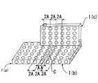
そこで、上記のような事態に対応する組立板材として、図16(a)に示されるように、長手方向(図中の左右方向)に延びる連結穴101と、連結穴101と直交するように組立板材の裏表面を貫通し、かつ組立板材の長手方向に配列される連結穴102と、を備える、組立板材100が提案されている(例えば、特許文献1参照)。この組立板材100は、長手方向のいずれの位置で切断しても、その切断面に連結穴101が必ず開口することになるとともに、長手方向に配列される連結穴102が形成されているため、連結穴を新たに形成する必要がない。これにより、長手方向において適当な寸法に切断するだけで、ユーザーにおける家具等の寸法変更が容易に行なわれるものである。
Therefore, as shown in FIG. 16A, a
ただし、上記の組立板材100のみで家具等を製作できるわけではなく、組立板材100と板幅方向(図中の上下方向)における寸法が同一で、図16(b)に示されるように、長手方向(図中の左右方向)に延びる連結穴201と、連結穴201と直交するように板材の裏表面を貫通する連結穴202とを備える組立板材200も使用する。この組立板材200は、組立板材100と同様に、長手方向のいずれの位置で切断しても、その切断面に連結穴201が開口するものである。連結穴201の板幅方向(図中の上下方向)における配列位置は、図16(a)における連結穴102の板幅方向(図中の上下方向)における配列位置と一致するようになっており、連結穴202の板幅方向における配列位置は、図16(a)における連結穴102の板幅方向における配列位置と一致するようになっている。
However, it is not always possible to manufacture furniture or the like using only the above-described assembled
上記のとおりであるから、組立板材100や組立板材200を長手方向のいずれの位置で切断した場合でも、板幅方向の位置さえ合わせれば、図16(c)に示されるように、連結穴101と連結穴202を一致させることができ(符号Q部分)、あるいは連結穴102と連結穴201とを一致させることができる(符号R部分)こととなって、両者を、連結穴の形状に合わせて形成された棒状の連結具300で容易に接合させることができるものである。その結果、ユーザー自らが、組立板材に連結穴を形成する必要はなく、容易に組立することができるものであり、また、家具等を分解して得られた組立板材を寸法変更して容易に再利用することができるものである。
ところで、上記した組立板材100では、連結穴101と連結穴102とで板幅方向の配列位置が異なるため、同じ組立板材100どうしを連結具300で接合させる場合、図17(a)で示されるように、長手方向で突き合せて連結穴101どうしを連結させるか、あるいは図17(b)で示されるように、板厚方向で重ね合せて連結穴102どうしを連結させる以外に接合することはできなかった。同様に、同じ組立部材200どうしを連結具300で接合させる場合も、長手方向で突き合せるか、板厚方向で重ね合せる以外に接合することはできない。また、異なる組立部材100と組立部材200を連結具300で接合する場合には、連結穴の配列位置の関係上、図17(c)に示されるように、一方を他方に直交方向で突き当てて、連結穴101と202を連結させるか、連結穴102と201を連結させる以外に接合することはできなかった。
By the way, in the above-mentioned assembled
そのため、縦方向(垂直方向)に延びる側壁板に、横方向(水平方向)に延びる天板や棚板を架け渡して、収納棚等の家具を組み立てる場合、例えば、図18(a)に示される収納棚のように、組立板材200を縦方向にして使えば、もう一方の組立板材100は横方向にしか使うことができなかった。すなわち、組立板材を接合する場合には、両方の接合面に配列位置の合致する連結穴が形成されているか否かを確認する必要があり、縦横方向を気にせずに自由に組替えすることはできないものであった。また、組立板材を手配する際に、縦方向にして使うものと横方向に使うものとで区別して、発注する必要があり、大変煩わしかった。
Therefore, when assembling furniture such as storage shelves by bridging a top plate or a shelf plate extending in a horizontal direction (horizontal direction) over a side wall plate extending in a vertical direction (vertical direction), for example, as shown in FIG. When the assembled
しかも、図18(a)に示されるような収納棚に棚板を設ける場合には、棚板を架け渡す2枚の側壁板について、連結穴202の高さ位置が一致させておく必要があり、もしそのような配慮を怠った場合には、図16(c)に一点鎖線で示される中間棚Mのように、両端を連結穴202に合わせることができない事態を招くこととなる。そのために、横方向に延びる棚板等を設ける場合には、縦方向に延びる側壁板等の連結穴について、高さ位置を予め寸法計算して一致させておかなければならないという煩わしさがあった。
In addition, when a shelf is provided on a storage shelf as shown in FIG. 18A, the height position of the
また、上記の組立板材について、異なる組立板材100と200を直交させて接合する場合であっても、例えば、図18(b)に示されるように、突き当てられる一方の組立板材(ここでは組立板材200)が、他方の組立板材(ここでは組立板材100)の板幅方向に対して直交する向きとなっている場合には、対向する連結穴102と連結穴201のピッチが異なっているため、連結具300で相互に連結することはできない。したがって、このような向きで組立板材を接合するような場合、例えば図18(a)に示される収納棚に背板を設ける場合には、連結穴のピッチを変更した組立板材を別途準備するか、連結穴による接合を諦めて収納棚の後面から板材をあてて釘打ちするかのいずれかで対応するしかなかった。
Also, in the above-described assembled plate material, even when different assembled
なお、ピッチを変更した組立板材を準備したとしても、連結穴102は端縁部100aよりも大きく内側(図中の手前側)に入り込んでいるため、収納スペースが著しく狭められるという問題があり、板材を釘打ちする場合には、ユーザーによる組立が困難であったり、板材が割れてしまったり、分解した組立板材を再利用する際に釘打ちの跡が目立ったりする等の不都合が生じる。
Even if an assembled plate material with a changed pitch is prepared, there is a problem that the storage space is significantly narrowed because the
さらに、上記の組立板材100,200は、長手方向には寸法変更することができるものの、板幅方向には寸法変更できないために、例えば、図18(c)に示されるような収納棚について、一点鎖線で示されるような奥行きの変更をすることはできないという問題があった。
Further, although the dimensions of the above-mentioned assembled
また、図19(a)及び図19(b)に示されるように、例えば、高さH、奥行きDの異なる複数種類の書籍a,b,cを収納棚に収納する場合において、奥行き寸法の小さい書籍aが、他の奥行き寸法の大きい書籍より奥に入り込んでいるため背表紙が見えにくかったり、取り出しにくかったりすることがある。そこで、図19(c)に示されるように、すべて書籍の背表紙側の奥行き方向の位置を面一に揃えることができるように、収納棚の奥行きを部分的に変更することができればよいが、上記した組立板材では、連結穴が形成される位置の関係上、そのような対応をすることができなかった。 As shown in FIGS. 19A and 19B, for example, when a plurality of types of books a, b, and c having different heights H and depths D are stored in storage shelves, the depth dimension Since the small book a is deeper than the other books having a large depth dimension, the spine may be difficult to see or take out. Therefore, as shown in FIG. 19C, the depth of the storage shelf may be partially changed so that the positions in the depth direction on the spine side of the book can be all flush. However, in the above-described assembled plate material, such a correspondence cannot be made due to a position where the connection hole is formed.
その他、図20に示されるように、例えば、室内に形成される梁の出っ張りを避けながら収納棚を設置するような場合には、一点鎖線で示されるように、収納棚の一部(符号Uで示される部分)について幅や奥行きを変更したい場合があるが、上記した組立板材では、そのような対応をすることができなかった。 In addition, as shown in FIG. 20, for example, when the storage shelves are installed while avoiding the protrusion of the beam formed in the room, a part of the storage shelves (reference numeral U) is indicated by a dashed line. In some cases, it is desired to change the width and the depth of the portion (indicated by a circle), but such an assembly plate cannot provide such a measure.
本発明は、斯かる実情に鑑みて、縦横方向の制約なく使い回しでき、連結穴の位置を合わせるために寸法計算する等の煩わしい作業を必要がなく、組み立てられる収納棚等の形状を自由に設定することができる組立板材を提供しようとするものである。 In view of such circumstances, the present invention can be reused without restrictions in the vertical and horizontal directions, does not require cumbersome work such as calculating the size to adjust the position of the connection hole, and can freely set the shape of the storage shelf and the like to be assembled. It is an object to provide an assembling plate material that can be set.
請求項1の発明は、直方体形状に形成され、かつ、前記直方体形状を構成する構成面に、連結具を挿入固着するための連結穴を複数個備えてなり、前記連結穴に挿入固着された連結具を介して連結することにより相互に接合される組立板材であって、前記連結穴は、前記構成面のすべてにおいて、碁盤目状に配置されており、相互に隣接する前記連結穴間の中心距離は、すべての構成面どうしで等間隔に設定されていることを特徴とする組立板材を提供する。なお、ここで、「碁盤目状に配置」とは、縦方向及び横方向において等間隔となるように配置されることを意味することから、一般に、縦横両方向に複数個の連結穴が並ぶ場合をいうものと考えられるが、本願においては、これに限定せず、複数個の連結穴が一列に等間隔で並ぶものも「碁盤目状に配置」されているものに含めるものとする。
The invention according to
請求項2の発明は、請求項1に記載の組立板材であって、前記直方体形状の各構成面における前記連結穴の中心線は、隣接する4つの構成面における前記連結穴の中心線と相互に直交することを特徴とする組立板材を提供する。
The invention according to
請求項3の発明は、請求項2に記載の組立板材であって、前記構成面における端縁部に隣接する前記連結穴は、その中心から前記端縁部までの距離が、前記連結穴間の中心距離の2分の1に設定されていることを特徴とする組立板材を提供する。 According to a third aspect of the present invention, in the assembly plate member according to the second aspect, the distance between the center of the connection hole adjacent to the edge and the edge of the component surface is equal to the distance between the connection holes. Provided at a half of the center distance.
請求項4の発明は、請求項3に記載の組立板材であって、板厚が、前記連結穴間の中心距離と同一に設定されていることを特徴とする組立板材を提供する。
[4] The invention according to claim 4 provides the assembled plate material according to
請求項1の発明によれば、以下の優れた効果を奏し得る。請求項1の発明に係る組立板材は、すべての構成面に連結穴を備えるとともに、相隣接する連結穴との中心距離がすべて等間隔となる碁盤目状に配置され、しかもすべての構成面どうしで中心距離が同一に設定されているので、組立板材を接合する場合において、接合面に配列位置の合致する連結穴が形成されているか否かを確認する必要がなく、板材の縦横方向を気にせずに組立・組替をすることができる。 According to the first aspect of the invention, the following excellent effects can be obtained. The assembled plate material according to the first aspect of the present invention is provided with connecting holes on all the constituent surfaces, and is arranged in a grid pattern in which the center distances between adjacent connecting holes are all equal, and all the constituent surfaces are connected to each other. Since the center distances are set to the same value, it is not necessary to check whether or not connection holes matching the arrangement position are formed in the joint surface when joining the assembled plate materials. Assembly and rearrangement can be performed without the need for any trouble.
また、上記従来の組立板材とは異なり、連結穴のピッチがすべて同一であるために、連結穴のピッチが異なる複数種類の組立板材を準備する必要が無い。その結果、組立板材の製造現場において、組立板材の製造設備を複数台設置したり、製造される組立板材の連結穴のピッチを変更するために段取り換えの時間を割いたりしなくてもよく、製造コストを低く抑えることができるものである。製品のラインアップ構成がシンプルになるので、販売現場においても、商品の発注ミス等を確実に防止して業務の効率化を図ることができるものである。 Also, unlike the above-mentioned conventional assembly plate materials, since the pitches of the connection holes are all the same, it is not necessary to prepare a plurality of types of assembly plate materials having different connection hole pitches. As a result, at the assembly plate material manufacturing site, there is no need to install a plurality of assembly plate material manufacturing facilities or take the time for setup change in order to change the pitch of the connection holes of the assembly plate material to be manufactured. The manufacturing cost can be kept low. Since the product lineup configuration is simplified, it is possible to reliably prevent product ordering errors and the like at the sales site and to improve the efficiency of operations.
さらに、連結穴が組立板材のすべての面に碁盤目状に形成されているので、他の組立板材を接合させる場合に、その連結位置に対する制限が少ないものである。その結果、収納棚等を組み立てる場合に、その全体あるいは一部分について、奥行きや高さ等を容易に変更することができ、例えば、収納対象物に応じて奥行きを変更したり、設置場所に応じて外形を異形に形成したりすることができるものである。 Furthermore, since the connection holes are formed in a grid pattern on all surfaces of the assembly plate material, there is little restriction on the connection position when joining other assembly plate materials. As a result, when assembling the storage shelf or the like, the depth or height of the whole or a part thereof can be easily changed, for example, the depth can be changed according to the storage object, or according to the installation location. The outer shape can be formed in an irregular shape.
請求項2の発明によれば、請求項1の発明が奏する効果に加えて、以下の優れた効果を奏する。請求項2の発明に係る組立板材は、1の構成面における連結穴の中心線が、隣接する4つの構成面における連結穴の中心線と相互に直交しているため、連結具で組立板材を接合させる場合において、接合位置の確認を容易に行うことができるものである。例えば、接合面そのものを覗き込みながら連結具を差し込まなくても、隣接する面に形成される連結穴によって、連結穴の位置確認ができるため、組立作業がし易くなるものである。
According to the invention of
請求項3の発明によれば、請求項2の発明が奏する効果に加えて、以下の優れた効果を奏する。請求項3の発明に係る組立板材は、端縁部からそれに隣接する連結穴の中心までの距離が、連結穴どうしの中心距離の2分の1に設定されている。そのため、組立板材の端縁部どうしを突き合せて接合させた場合に、その接合部分を挟んで隣接する連結穴どうしの中心距離が、他の一般部における連結穴どうしの中心距離と同一となる。その結果、接合された2枚の組立板材1に跨るように、他の組立板材1を接合することが何ら支障無く行えるものであり、組立板材の接合部を挟む連結穴どうしの中心距離を予め計算し、その計算結果に合わせて連結穴間のピッチが異なる組立板材を新たに準備する必要が無いものである。
According to the invention of
また、2つの組立板材を直交させて接合した場合に、その接合部(コーナー部)から、これに隣接する連結穴の中心までの距離は、組立板材の端縁部から隣接する連結穴の中心までの距離と同じになる。したがって、この接合部に他の組立板材のコーナー部を、隙間無く接合することができるものであり、接合部における連結穴の位置を予め計算したり、それに合わせて端縁部から連結穴の中心まで距離が異なる組立板材を新たに準備したりする必要が無いものである。 その結果、組立板材の外形寸法さえ適合していれば、収納ボックス、収納棚、ワゴン、テーブル等の家具は、室内のレイアウトや収納対象物に応じて、容易に組み立てできるものである。 When two assembled plate members are joined at right angles to each other, the distance from the joint (corner portion) to the center of the adjacent connection hole is determined by the distance between the edge of the assembly plate member and the center of the adjacent connection hole. To the same distance. Therefore, it is possible to join the corner portion of another assembly plate material to this joint portion without any gap, and calculate the position of the connection hole at the joint portion in advance, or adjust the position of the connection hole from the edge to the center of the connection hole. It is not necessary to newly prepare an assembly plate material having a different distance up to the distance. As a result, furniture such as storage boxes, storage shelves, wagons, and tables can be easily assembled according to the layout of the room and the objects to be stored, as long as the outer dimensions of the assembled plate material are suitable.
以下、本発明の実施の形態を、添付図面を参照しつつ説明する。 Hereinafter, embodiments of the present invention will be described with reference to the accompanying drawings.
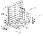
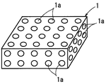
図1〜12は、本発明の実施形態の一例を示す図である。図1は、本実施形態に係る組立板材1の単品斜視図、図2は、図1のX−X断面図、図3は、図1のY−Y断面図である。図4は、複数の組立板材1を相互に連結するための連結具2の単品図で、(a)は側面図、(b)は断面図である。図5は、2枚の組立板材1を接合する際の様子を示す図であり、図6は接合された状態を示す図である。図7は、端縁部を突き合せて接合された2枚の組立板材1に跨るように、他の組立板材1を接合させた状態を示す斜視図である。図8は、相互に直交するように接合された2枚の組立板材1に跨るように、他の組立板材1を接合させた状態を示す斜視図である。図9は、図8におけるZ‐Z断面図である。
FIGS. 1 to 12 are diagrams showing an example of an embodiment of the present invention. FIG. 1 is a perspective view of an assembled
〔組立板材1〕
組立板材1は、図1〜3に示されるように、6つの構成面11〜16で構成される直方体形状に形成されるブロック状板材である。6つの構成面11〜16は、すべて、連結具2(図4)を挿入固着するための連結穴1aを複数個備えている。これにより、複数枚の組立板材1を、連結穴1aに挿入固着される連結具2を介して連結し、構成面どうしで相互に接合することができるものである。なお、図1〜3においては、説明の便宜上、連結穴1aには、各構成面の名称に合わせて、11a,12a,13a,14a,15a,16aの符号を付している。また、図1及び図3において、11a,16aは、構成面11、16上に20個形成されているが、その符号記載を一部又は全部省略している。
[Assembled plate 1]
As shown in FIGS. 1 to 3, the assembled
組立板材1の直方体形状は、図1からわかるように、高さ(板厚)H、長さL、幅Wの寸法が2Aの整数倍となる大きさに形成されている。すなわち、組立板材1は、寸法2A角の立方体が一体的に連結されて、全体として直方体形状を形成するような寸法形状のものとされている。なお、図1〜3に示される組立板材1では、高さHの寸法は2A(2Aの1倍)、長さLの寸法は10A(2Aの5倍)、幅Wの寸法は8A(2Aの4倍)に設定されている。例えば、A=2cmとすれば、高さ2cm、長さ10cm、幅8cmの組立板材を形成することになる。ただし、これらのA,5A,4A等の寸法は、図面作成のために任意に設定したものであって、組立板材1の大きさや、組立板材1の高さ・幅・長さの寸法比率を限定するものではない。したがって、他の図面において、図1〜3に示される組立板材1と異なる大きさ・寸法比率を有する組立板材に、同じ符号1の表示を付しているが、誤りではない。
As can be seen from FIG. 1, the rectangular parallelepiped shape of the assembled
連結穴1aは、図1〜3に示されるように、構成面11〜16のすべてにおいて、碁盤目状に配置されている。この碁盤目の縦横方向で相隣接する連結穴の中心距離は、すべての構成面11〜16において、同一寸法2Aに設定されている。また、各構成面11〜16における碁盤目の縦横の配列方向は、各構成面の端縁部に対して平行とされている。さらに、各構成面における連結穴11a〜16aの中心線11o〜16o(これらの中心線は不図示。)は、4つの隣接する構成面に形成される連結穴の中心線と相互に直交する位置に配置されている。例えば、連結穴11aを例にすると、その中心線11oは、4つの隣接する構成面12〜15に形成される連結穴12a〜15aの中心線12o〜15oと相互に直交する。したがって、当然ながら、各構成面に形成される連結穴の中心線は、それぞれの裏側の構成面に形成される連結穴の中心線と一致する。すなわち、連結穴11aと16a、12aと14a、13aと15aについて、中心線は相互に一致するものである。
As shown in FIGS. 1 to 3, the connection holes 1 a are arranged in a grid pattern on all of the
連結穴1a、すなわち11a〜16aは、円筒形状穴であって、すべて内径D1(<2A)及び長さL1(=2A)となるように形成されている。連結穴1aの内径D1を2Aより小さくしたのは、後述するように連結穴1aどうしの中心距離が2Aとされる条件の下でも、連結穴1aどうしが相互に重ならないようにするためである。なお、図1〜3に示される組立板材1では、高さ(板厚)Hの寸法が、連結穴1aの長さL1と同一の2Aに設定されているので、構成面11,16に形成される連結穴11a,16aは、図2に示されるように、相互に裏側の構成面まで貫通して、両者共通に構成されるものとなっている。
The connection holes 1a, that is, 11a to 16a are cylindrical holes, and are all formed to have an inner diameter D1 (<2A) and a length L1 (= 2A). The reason why the inner diameter D1 of the
連結穴1aは、図1〜図3に示されるように、各構成面11〜16において縦横方向に相隣接する連結穴1aどうしの中心距離が2Aとなるように、かつ、各構成面11〜16において、その端縁部とそれに隣接する連結穴1aの中心との距離がAとなるように設定されている。すなわち、各構成面11〜16において端縁部に隣接する連結穴1aは、その中心から端縁部までの距離が、相互に相隣接する連結穴1aどうしの中心距離の2分の1に設定されるものである。なお、「碁盤目状に配置」とは、縦方向及び横方向のいずれにおいても等間隔に配置されることを意味することから、一般に、縦横両方向に複数個の連結穴が並ぶ場合をいうものと考えられるが、ここでは、連結穴12a,13a,14a,15aのように、複数の連結穴が一列に等間隔で並ぶものについても「碁盤目状に配置」されているものに含めるものとする。
As shown in FIGS. 1 to 3, the connection holes 1 a are arranged such that the center distance between the adjacent connection holes 1 a in the vertical and horizontal directions on each of the component surfaces 11 to 16 is 2 A, and each of the component surfaces 11 to 16. At 16, the distance between the edge and the center of the connecting
〔連結具2〕
連結具2は、連結穴1aに挿入固着されて、組立板材1を接合した状態に連結するために使用される。連結具2は、図4に示されるように、外径D2(<2A)、長さL2(=4A)の断面円形の棒状体であって、その外周面2aには、軸心方向に延びる複数本の溝21が、周方向で所定間隔をおいて形成されている。連結具2の外径D2は、連結具2が連結穴1aに挿入されたときに、連結穴1aの内周面に嵌合した状態となって容易に外れることを防止するよう締代を確保するため、連結穴の内径D1より僅かに大きく設定されている。
[Connector 2]
The connecting
ただし、連結穴1aの内周面に対する連結具2の挿入抵抗が大きくなりすぎると、組立板材1の組付が困難となったり、連結穴1aの周囲に割れが生じたりするおそれがある。そこで、溝21を設けることにより、連結具2の表面が潰れやすくなるようにしたり、両者の挿入面積が小さくなるように調整したりして、組立性を確保している。また、溝21は、組立板材1から容易に外れないように強固に接合したい場合に、接着剤を介在させるスペースとしても使用することができるものである。なお、連結具2は、その長さL2が、連結穴1aの長さL1の2倍である4Lに設定されているので、接合されるものである。なお、ここでは、連結具2を内部が詰まった中実体として形成したが、中空体となるように形成しても良い。また、ここでは、連結具2の外径D2を、連結穴1aの内径D1より大きくして締代を確保したが、必ず接着剤が使用される場合には、外径D2を内径D1と同径かあるいは小さくしても良い。
However, if the insertion resistance of the connecting
〔組立板材1の接合〕
組立板材1による家具等の組立は、多数の組立板材1を連結具2で連結し、接合することにより行われる。2枚の組立板材1を接合する場合、図5に示されるように、一方の組立板材1(図中における右側の組立板材1)の接合面に形成される連結穴1aに、連結具2を予め挿入固着しておく。そして、突出する連結具2の先端側を他方の組立板材1(図中における左側の組立板材1)の接合面に形成される連結穴1aに合わせて、接合面どうしを強く押し付ける。これにより、図6に示されるように、2枚の組立板材1が連結接合されることとなるものであるが、上述したように、連結具2の長さは、連結穴1aの長さ2Lの2倍(4L)に設定されているので、連結具2は、接合される2つ連結穴1aの内部に完全に収容されて、外部にはみ出すことがないものである。
[Joining of the assembled plate 1]
The assembly of furniture and the like using the assembled
組立板材1は、上述したように、直方体形状を形成するすべての構成面に連結穴1aを備えており、縦横方向に相隣接する連結穴1aの中心距離がすべて等間隔となる碁盤目状に配置され、しかもすべての構成面どうしで中心距離が同一(2A)に設定されている。したがって、組立板材1どうしを接合する場合において、接合面となる構成面に、相互に配列位置の合致する連結穴1aが設けられているか否かを確認する必要はなく、また、連結穴1aが、組立板材1の縦横方向のいずれに配列されているか等を気にする必要もないものである。したがって、組立板材1と連結具2からなる組立キットにより、組立板材1について、容易かつ自由に組立や組替をすることができるものである。
As described above, the
ところで、図5に示されるような組立板材1どうしの接合を行う場合には、連結穴1aの先端を、それが挿し込まれる連結具2の位置に合わせるため、接合面の連結穴1a(図5における左側の組立板材において点線で表される。)を直接覗き込んで作業する必要がある。しかしながら、接合面の連結穴1aは、隣接する構成面における連結穴1aと中心線が相互に直交することから、隣接する面に形成される連結穴1a(図5における左側の組立板材1において実線で表される。)を目安にして、連結具2との位置合わせをすることができるものである。したがって、必ずしも接合部分を直接覗き込む必要が無く、これにより組立作業が容易にできる場合も生じ得るものである。
By the way, when joining the assembled
なお、組立板材1に形成される家具等の組立強度を高く保つという観点からすれば、連結具2は、図5に示されるように、接合面に形成されるすべての連結穴1aに挿入しておくことが望ましい。しかし、あまり高い強度が必要とされない場合には、連結穴1aに対して一つおき連結具を固着する等、連結具2の数を減らすようにしても良い。また、組立板材1から連結具2が容易に抜けないように強固に取り付けたい場合には、連結穴1aに予め接着剤を流し込んでおくようにしても良い。組立板材1の連結穴1aに連結具2を挿入したり、組立板材1の接合面どうしを押し付けたりする際に、嵌め合いがきつい場合には、木槌等で叩き込む等するようにしても良い。
In addition, from the viewpoint of keeping the assembly strength of furniture and the like formed on the
〔接合された2つの組立板材に対する他の組立板材1の接合〕
組立板材1は、上述したように、各構成面の端縁部から、その端縁部に隣接する連結穴1aの中心までの距離が、連結穴どうしの中心距離2Aに対して、その2分の1であるAに設定されている。そのため、図7に示されるように、2枚の組立板材1(符号1(a)及び1(b)で示す。)を、端縁部どうしを突き合せて接合させた場合、その接合部分Cを挟んで相隣接する連結穴1aどうしの中心距離は、接合部分C以外の一般部における連結穴1aどうしの中心距離と同じ2Aとなる。その結果、突き合せるように接合された上記2枚の組立板材1に跨るように、他の組立板材1(同図において符号1(c)で示す。)を接合することが何ら支障無く行えるものである。したがって、組立板材1の接合部分Cを挟む連結穴どうしの中心距離がいくらになるか予め計算したり、その計算結果に合わせた連結穴間のピッチを有する組立板材を新たに準備したりする必要が無いものである。
[Joining of another assembled
As described above, the distance between the edge of each component surface and the center of the
また、図8に示されるように、2枚の組立板材1(符号1(d)及び1(e)で示す。)を直交させて接合した場合、その接合部分D(コーナー部分)から、この接合部分Dに隣接する連結穴1aの中心までの距離は、組立板材1の端縁部からそれに隣接する連結穴1aの中心までの距離と同じAとなる。その結果、直交するように接合された上記2枚の組立板材1に跨るようにして、他の組立板材1(同図において符号1(f)で示す。)を接合部分Dに隙間無く接合することを、何ら支障無く行えるものである。したがって、組立板材1を直交させた接合部分Dから連結穴1aの中心までの距離がいくらになるか予め計算したり、その計算結果に端縁部から連結穴までの距離を合わせた組立板材を新たに準備したりする必要が無いものである。
Further, as shown in FIG. 8, when two assembled plate members 1 (indicated by reference numerals 1 (d) and 1 (e)) are joined at right angles, this joint portion D (corner portion) The distance from the end of the
上記のとおりであるから、室内のレイアウトや収納対象物の寸法に合わせて、収納ボックス、収納棚、ワゴン、テーブル等の家具を組み立てする場合において、高さH・長さL・幅Wの寸法さえ適合した組立板材1を準備しておけば、連結穴1aの配列位置がどのようになっているか等を確認したり、組立板材1を接合部分における連結穴1aの位置関係(連結穴1aどうしのピッチや接合部分と連結穴1aとの距離)を計算したりする必要が無いものである。したがって、組立板材1と連結具2からなる組立キットにより、あたかもブロック玩具を扱うような感覚で、容易に家具等を組み立てることができるものである。
As described above, when assembling furniture such as storage boxes, storage shelves, wagons, and tables in accordance with the layout of the room and the dimensions of the storage object, dimensions of height H, length L, and width W are used. Even if an
なお、図8に示されるように、直交するように接合された2枚の組立板材1(d),1(e)に跨らせて、他の組立板材1(f)を接合させるときの組立手順を、図8のZ‐Z断面に相当する図9に基づいて説明する。まず、組立板材1(d),1(e)が連結具2(符号2(a)で示される。)で直交するように接合されたものに対して、連結具2(符号2(b)で示される。)を予め挿入固着した組立板材1(f)を押し当てることにより、組立板材1(e)と組立板材1(f)を連結する。 In addition, as shown in FIG. 8, when the other assembled plate material 1 (f) is joined over two assembled plate materials 1 (d) and 1 (e) joined orthogonally. The assembling procedure will be described with reference to FIG. 9 corresponding to the ZZ section in FIG. First, the connecting member 2 (reference numeral 2 (b)) is joined to the assembly plate members 1 (d) and 1 (e) joined orthogonally by the connecting member 2 (represented by reference numeral 2 (a)). Is pressed and pressed against the assembled plate 1 (f), which is inserted and fixed in advance, thereby connecting the assembled plate 1 (e) and the assembled plate 1 (f).
次に、組立板材1(f)の外側(図中の左側)から、連結穴1aに連結具2(符号2(c)で示される。)を挿入することにより、組立板材1(d)と組立板材1(f)が連結することによって、組立を完了するものである。高さ(板厚)Hを連結穴1aの長さと同一の2Aに設定することにより、連結穴1aが組立板材1の裏表を貫通するように形成されるので、組立板材1を合わせた状態としたうえで、連結具2を外側から挿通することができるものである。したがって、連結穴1aに連結具2を予め挿入しておかなくても済むものである。
Next, a connecting member 2 (indicated by reference numeral 2 (c)) is inserted into the connecting
〔組立板材1による家具等の組立例〕
次に、上記した組立板材1で構成される家具等の組立例について、図10〜13を参照しつつ説明する。
[Example of assembling furniture and the like using the assembly plate 1]
Next, an example of assembling furniture or the like constituted by the above-described assembled
図10は、連結具2により接合される組立板材1で構成される本棚3を示す斜視図である。なお、図10では、図を見易くするため、本来、表面に現れる連結穴1aの描画を一部省略している。本棚3は、大きさの異なる本a,b,c(図19参照。)をそれぞれ収納するための収納部3a,3b,3cを備えてなる。収納部3aは、組立板材1で形成される側壁板1(f)により仕切られており、組立板材1で形成される棚板1(g)で上下2段に分割されている。また、その背後には、やはり組立板材1で形成されて収納部3a奥行きを規制する規制板1(h)が設けられている。規制板1(h)は、奥行きの小さい本cが収納部3aの奥に入り込む(入り込んだ状態は図19(a)参照。)ことによって、本b,cや本棚の外側壁の陰になり、背表紙が見にくくなったり、取り出しにくくなったりすることを防止するため、本cの奥行きをかさ上げするものである。
FIG. 10 is a perspective view showing the
また、収納部3bは、本bが収納される部分であるが、規制板1(i)により本bの奥行きを僅かにかさ上げされるようになっており、これによって、僅かに奥行きの大きい本cと間に背表紙の段差を生じないようにすることができ、本棚3に大きさの異なる本が収納されたときの見栄えを良くすることができるものである。ここで、規制板1(h),1(i)は、側壁版や棚板とは、異なる向きに取り付けられるものであるが、組立板材1は、その構成面のすべてに等間隔で配列される連結穴1aを有しており、その連結穴1aの間隔がすべての構成面で共通とされているので、連結するための穴を開けなおしたり、穴間隔の異なる別の組立板材を準備したりする必要が無いものである。
The
図11は、連結具2により接合される組立板材1により構成される収納棚4を示す斜視図である。なお、図11において、組立板材の表面に現れる連結穴1aの描画は省略されている。この収納棚4は、天井部に水平方向に延びる梁が形成されている室内のコーナー部に設置するためのものであって、その本体棚41の最上部に、梁に沿わせるように構成される上部棚42が一体的に取り付けられているものである。
FIG. 11 is a perspective view showing the storage shelf 4 constituted by the assembled
上部棚42の幅・奥行き・高さの寸法は、梁の大きさによって定まるものであるが、これを構成する組立板材は、その構成面のすべてに等間隔で配列される連結穴1aを有しており、その連結穴1aの間隔がすべての構成面で共通とされているので、大きさや結合位置を変更することが容易に行われるものである。しかも、梁と対向しない部分(図中における手前側の側面、及び前面)については、本体棚41と上部棚42を面一に構成することができるので、両者には視覚的な一体感があり、まるで作りつけのような見栄えの良さが得られるものである。
The dimensions of the width, depth, and height of the
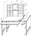
図12は、連結具2により接合される組立板材1により構成されるテーブル5を示す斜視図である。テーブル5は、主に本体部51と収納部52で構成される。本体部51は、図に示されるように、組立板材1を組み合わせることにより、幅・奥行き・高さの寸法を自由に変更することができるものであって、室内に張り出した柱(一点差線で示す。)を避ける切欠きが形成されている。また、本体部51の上面に一体的に設置される収納部52も、収納物の大きさに合わせて幅・奥行き・高さを自由に変えることができるようになっている。さらに、収納部52の間には、複数本の円筒形ロッド丸棒53が架け渡されており、収納棚あるいは物を吊り下げるためのハンガーとして使用できるようになっている。
FIG. 12 is a perspective view showing the table 5 constituted by the assembled
なお、本体部51は、強度を向上させるために、2枚(複数枚)の組立板材1を重ね合わせた状態で使用している。ここで、図13(a)に示されるように、複数枚の組立板材1を長さ方向や幅方向に接合したものを重ね合わせて使う場合には、図13(b)に示されるように、接合部分Cの位置を重ね合わされる部分を相互にずらすことにより、より高い強度を得ることができるものである。
The
また、図12において、本体部51や収納部52の表面には、連結穴1aが現れていない部分あるが、これは、本体部51や収納部52の形状に合わせてカッティングされた硬質樹脂製の薄型フラットシート6が取り付けられているためである。この薄型フラットシート6は、表面側が平坦に形成されている一方において、本体部51や収納部52の表面に接する裏面側に碁盤目状に配列されて、本体部51の連結穴1aに対して着脱自在に嵌合する突起を備えているものである。これにより、本体部51の上面を使う際の作業性や、収納部52に細かいもの細かいものを収納する際の収納性を確保することができ、また、テーブル5の上方から下部が見えないように目隠ししたり、テーブルのカラーリングを変更したりすることができるものである。
In FIG. 12, there is a portion where the
上記のとおり、組立板材1は、すべての構成面に連結穴が等間隔で形成されているので、複数の組立板材1を連結具2で連結して接合させる場合に、その連結位置に対する制限が少なく、収納棚等の家具を組み立てる場合に、その全体あるいは一部分について、奥行きや高さ等を容易に変更することができるものである。例えば、収納対象物に応じて奥行きを変更したり、設置場所に応じて、例えば梁や柱の出っ張りに対応するように、外形を異形に形成したりすることができるものである。
As described above, since connection holes are formed at equal intervals in all the constituent surfaces of the
〔組立板材1自体の製造等〕
上述したように、組立板材1を使用することによって、素人でも様々な形状の家具等を容易に組み立てることができるものであるが、組立板材1自体を製造等する場合においても、次のようなメリットがある。
[Manufacture of assembled
As described above, by using the assembled
組立板材1は、連結穴1aの配列ピッチがすべて同一となるように設定されているため、上記従来の組立板材のように、連結穴の配列ピッチが異なる複数種類の組立板材を準備する必要が無い。したがって、組立板材1の製造現場において、配列ピッチの異なる組立板材を製造するために、製造設備を複数台設置したり、製造される組立板材の連結穴のピッチを変更するために段取り換えの時間を割いたりしなくてもよいものである。その結果、製造コストを低く抑えることができるものである。また、組立板材の製品としてのラインアップ構成もシンプルにすることができるので、販売現場においても、商品の発注ミス等を確実に防止して業務の効率化を図ることができるものである。
Since the arrangement pitch of the connecting
組立板材1の材質としては、使用用途に応じて、木材、樹脂等、様々なものから選択採用することができる。木材で構成される場合には、木材から所定寸法の板材を切り出した後で、ドリル等により穴あけすることにより形成することができるものである。また、ABS、PE、PP等の樹脂で構成される場合には、スライド型を備えた射出成形型等により、外形と連結穴1aを同時に形成することができるものである。連結具2の材質についても同様に、様々なものから選択することができるものである。
材質 As the material of the
〔上記実施形態の変形例〕
上記実施形態では、組立板材1に形成される連結穴1aは単なる円筒形状に形成されていたが、図14(a)に示されるように、連結穴1aの周縁部に棚状の段差部1pを設けるようにしても良い。連結穴1aに挿入される連結具2に対して、段差部1pの内径と同じ外径を有する大径部2pを形成することにより、相互に連結される組立板材1の接合部の強度をより向上させることができるものである。また、上記実施形態では、連結穴1aと連結具2は、これらの内外径寸法の違いによる締代で嵌合状態を維持するものとしていたが、両者に相互に係合する突起と凹部の組合せからなる抜け止めを設けることにより嵌合状態を維持するようにしても良い。その他、上記実施形態では、連結具2の長さ寸法は、連結穴1aの長さ2Aの2倍となる4Aに設定されていたが、接合される2つの連結穴1aの中に収納され、かつ組立板材1どうしの接合に支障がない範囲内であれば、連結具2の長さ寸法を変更することも可能である。
[Modification of the above embodiment]
In the above-described embodiment, the connecting
上記実施形態では、組立板材1の高さ(板厚)Hが、連結穴1aの中心距離と同じ2Aに設定されていたが、図15に示されるように、それより大きな寸法に設定しても良い。また、上記実施形態において、連結穴1aの長さは、連結穴1aどうしの中心距離と同じ2Aに設定されていたが、連結具2を接合される2つの連結穴1aの中に収納することができ、かつ組立板材1どうしの接合に支障がない範囲内であれば、2Aとは異なる寸法に変更することも可能である。
In the above embodiment, the height (plate thickness) H of the assembled
上記実施形態では、組立板材は、本棚、収納棚、テーブル等の家具等を組み立てるための素材として説明したが、これに限定されず、建築用資材となるように形成しても良い。建築用資材として使用する場合には、建設現場でスケールを当てて寸法を正確に測ったり、鋸で切断したりする煩わしい作業が少なくなり、経験の浅い者でも連結具を使って容易に組み立てを行うことができ、万一、寸法を誤って組み付けるようなことがあっても分解して組み直すことができるものである。なお、建設資材として使用される場合には、この木材・樹脂のほかにコンクリートで形成されるパネルとして採用することもできる。 In the above-described embodiment, the assembled plate material has been described as a material for assembling furniture such as a book shelf, a storage shelf, and a table. However, the present invention is not limited to this, and may be formed as a building material. When used as a building material, there is less troublesome work such as applying a scale at a construction site to accurately measure dimensions and cutting with a saw, and even inexperienced people can easily assemble using connecting tools. It can be disassembled and reassembled even if the dimensions are incorrectly assembled. When used as a construction material, it can also be used as a panel formed of concrete in addition to the wood and resin.
また、子供用の組立玩具として使用する場合、従来の組立玩具のように、一方向にしか連結できないものと異なり、上下左右前後に自由に組立可能であることから、バリエーションに富んだものを組み立てることができるものである。 Also, when used as a children's assembly toy, unlike conventional assembly toys that can be connected only in one direction, they can be freely assembled up, down, left, right and front, so assemble a variety of toys Is what you can do.
その他、本発明の組立板材は、上記した実施の形態に限定されるものではなく、本発明の要旨を逸脱しない範囲内において種々変更を加え得ることは勿論である。 Otherwise, the assembled plate material of the present invention is not limited to the above-described embodiment, and it goes without saying that various changes can be made without departing from the spirit of the present invention.
1 組立板材
1a 連結穴
2 連結具
DESCRIPTION OF
Claims (4)
前記連結穴は、前記構成面のすべてにおいて、碁盤目状に配置されており、
相互に隣接する前記連結穴間の中心距離は、すべての構成面どうしで等間隔に設定されていることを特徴とする組立板材。 It is formed in a rectangular parallelepiped shape, and comprises a plurality of connecting holes for inserting and fixing a connecting tool on a constituent surface constituting the rectangular parallelepiped shape, and connecting via a connecting tool inserted and fixed to the connecting hole. Assembly plate material that is joined to each other by
The connection holes are arranged in a grid pattern on all of the constituent surfaces,
An assembly plate material, wherein a center distance between the adjacent connection holes is set to be equal at all the constituent surfaces.
前記直方体形状の各構成面における前記連結穴の中心線は、隣接する4つの構成面における前記連結穴の中心線と相互に直交することを特徴とする組立板材。 The assembly plate material according to claim 1, wherein
An assembly plate material, wherein a center line of the connection hole in each of the rectangular parallelepiped component surfaces is orthogonal to a center line of the connection hole in four adjacent component surfaces.
前記構成面における端縁部に隣接する前記連結穴は、その中心から前記端縁部までの距離が、前記連結穴間の中心距離の2分の1に設定されていることを特徴とする組立板材。 It is an assembly board | plate material of Claim 2, Comprising:
The assembling method, wherein a distance from the center of the connection hole adjacent to the edge portion on the configuration surface to the edge portion is set to a half of a center distance between the connection holes. Board material.
板厚が、前記連結穴間の中心距離と同一に設定されていることを特徴とする組立板材。 It is an assembly board | plate material of Claim 3, Comprising:
An assembled plate material, wherein a plate thickness is set to be equal to a center distance between the connection holes.
Priority Applications (1)
| Application Number | Priority Date | Filing Date | Title |
|---|---|---|---|
| JP2003406439A JP3628681B2 (en) | 2003-12-04 | 2003-12-04 | Assembly plate material |
Applications Claiming Priority (1)
| Application Number | Priority Date | Filing Date | Title |
|---|---|---|---|
| JP2003406439A JP3628681B2 (en) | 2003-12-04 | 2003-12-04 | Assembly plate material |
Publications (2)
| Publication Number | Publication Date |
|---|---|
| JP2004089729A true JP2004089729A (en) | 2004-03-25 |
| JP3628681B2 JP3628681B2 (en) | 2005-03-16 |
Family
ID=32064739
Family Applications (1)
| Application Number | Title | Priority Date | Filing Date |
|---|---|---|---|
| JP2003406439A Expired - Fee Related JP3628681B2 (en) | 2003-12-04 | 2003-12-04 | Assembly plate material |
Country Status (1)
| Country | Link |
|---|---|
| JP (1) | JP3628681B2 (en) |
Cited By (8)
| Publication number | Priority date | Publication date | Assignee | Title |
|---|---|---|---|---|
| WO2006035742A1 (en) * | 2004-09-29 | 2006-04-06 | Hic Co., Ltd. | Combination housing furniture |
| JP2007075567A (en) * | 2005-09-13 | 2007-03-29 | Kitazono Seizaisho:Kk | Piece of knockdown type furniture changing according to growth of child (family) |
| JP2009022559A (en) * | 2007-07-20 | 2009-02-05 | Namco Bandai Games Inc | Prize acquisition game device |
| WO2010095631A1 (en) * | 2009-02-19 | 2010-08-26 | 株式会社バンダイナムコゲームス | Support mechanism for prize winning game apparatus, and prize winning game apparatus |
| JP2010279469A (en) * | 2009-06-03 | 2010-12-16 | Sogo Plastic:Kk | Knock-down shelf |
| JP2011089360A (en) * | 2009-10-26 | 2011-05-06 | Intenza:Kk | Assembling structure of partition furniture |
| EP2371240A1 (en) * | 2008-12-31 | 2011-10-05 | Xiaozhong Xu | Systematic board-type furniture and manufacture method of the components in the furniture |
| KR101136977B1 (en) | 2010-04-26 | 2012-04-19 | 안현수 | Prefabricated furniture having various uses |
-
2003
- 2003-12-04 JP JP2003406439A patent/JP3628681B2/en not_active Expired - Fee Related
Cited By (10)
| Publication number | Priority date | Publication date | Assignee | Title |
|---|---|---|---|---|
| WO2006035742A1 (en) * | 2004-09-29 | 2006-04-06 | Hic Co., Ltd. | Combination housing furniture |
| JP2007075567A (en) * | 2005-09-13 | 2007-03-29 | Kitazono Seizaisho:Kk | Piece of knockdown type furniture changing according to growth of child (family) |
| JP2009022559A (en) * | 2007-07-20 | 2009-02-05 | Namco Bandai Games Inc | Prize acquisition game device |
| EP2371240A1 (en) * | 2008-12-31 | 2011-10-05 | Xiaozhong Xu | Systematic board-type furniture and manufacture method of the components in the furniture |
| EP2371240A4 (en) * | 2008-12-31 | 2013-06-26 | Xiaozhong Xu | Systematic board-type furniture and manufacture method of the components in the furniture |
| WO2010095631A1 (en) * | 2009-02-19 | 2010-08-26 | 株式会社バンダイナムコゲームス | Support mechanism for prize winning game apparatus, and prize winning game apparatus |
| JP2010188010A (en) * | 2009-02-19 | 2010-09-02 | Namco Bandai Games Inc | Support mechanism for prize winning game apparatus, and prize winning game apparatus |
| JP2010279469A (en) * | 2009-06-03 | 2010-12-16 | Sogo Plastic:Kk | Knock-down shelf |
| JP2011089360A (en) * | 2009-10-26 | 2011-05-06 | Intenza:Kk | Assembling structure of partition furniture |
| KR101136977B1 (en) | 2010-04-26 | 2012-04-19 | 안현수 | Prefabricated furniture having various uses |
Also Published As
| Publication number | Publication date |
|---|---|
| JP3628681B2 (en) | 2005-03-16 |
Similar Documents
| Publication | Publication Date | Title |
|---|---|---|
| US8733851B2 (en) | Modular furniture system | |
| ES2256545T3 (en) | SOIL COATING. | |
| KR101338860B1 (en) | Portable Floor Panel and Portable Floor System Comprising a Plurality of Such Panels | |
| US20030016992A1 (en) | Combined connecting and alignment system for composite fiber building panels | |
| US20060185287A1 (en) | Portable floor and method of manufacture and installation | |
| US10961702B2 (en) | System and method of interlocking wall panels | |
| GB2482213A (en) | Cabinet assembly | |
| US20070209318A1 (en) | Modular panel assembly | |
| US4058909A (en) | Construction kit | |
| CA2235914C (en) | Joint | |
| JP2004089729A (en) | Assembly plate | |
| US6283668B1 (en) | No-slip corner joint | |
| US6520831B1 (en) | Modular doll house | |
| US9027299B2 (en) | Themed modular ceiling and wall decor kit and system | |
| US20210076824A1 (en) | Assemblable wood brick | |
| US5167103A (en) | Log-look siding corner blocks | |
| JP2005155731A (en) | Connector and joint structure of frame member using it | |
| US20070193219A1 (en) | Decorative paneling system for wall | |
| EP2537438A1 (en) | Furnishing element such as a bookcase, shelves, shelving or suchlike | |
| JP2017128990A (en) | Assembly block, assembly block set, cap, assembly method for three-dimensional structure | |
| JP3384542B2 (en) | Connection structure of multiple members | |
| JP2010018963A (en) | Lattice structure for partition, and its assembling construction method | |
| JPH0547204Y2 (en) | ||
| JP3955997B2 (en) | Edge frame for tatami mat | |
| JPH0241037B2 (en) | JUTAKUMOKEINOKOSEISOCHI |
Legal Events
| Date | Code | Title | Description |
|---|---|---|---|
| RD01 | Notification of change of attorney |
Effective date: 20031209 Free format text: JAPANESE INTERMEDIATE CODE: A7426 |
|
| A521 | Written amendment |
Effective date: 20031209 Free format text: JAPANESE INTERMEDIATE CODE: A821 |
|
| A621 | Written request for application examination |
Free format text: JAPANESE INTERMEDIATE CODE: A621 Effective date: 20040525 |
|
| A871 | Explanation of circumstances concerning accelerated examination |
Effective date: 20040607 Free format text: JAPANESE INTERMEDIATE CODE: A871 |
|
| A975 | Report on accelerated examination |
Effective date: 20040615 Free format text: JAPANESE INTERMEDIATE CODE: A971005 |
|
| A131 | Notification of reasons for refusal |
Effective date: 20040824 Free format text: JAPANESE INTERMEDIATE CODE: A131 |
|
| A521 | Written amendment |
Free format text: JAPANESE INTERMEDIATE CODE: A523 Effective date: 20040928 |
|
| TRDD | Decision of grant or rejection written | ||
| A01 | Written decision to grant a patent or to grant a registration (utility model) |
Effective date: 20041207 Free format text: JAPANESE INTERMEDIATE CODE: A01 |
|
| A61 | First payment of annual fees (during grant procedure) |
Free format text: JAPANESE INTERMEDIATE CODE: A61 Effective date: 20041208 |
|
| R150 | Certificate of patent (=grant) or registration of utility model |
Free format text: JAPANESE INTERMEDIATE CODE: R150 |
|
| FPAY | Renewal fee payment (prs date is renewal date of database) |
Free format text: PAYMENT UNTIL: 20071217 Year of fee payment: 3 |
|
| FPAY | Renewal fee payment (prs date is renewal date of database) |
Year of fee payment: 6 Free format text: PAYMENT UNTIL: 20101217 |
|
| LAPS | Cancellation because of no payment of annual fees |