JP2004088759A - Controller, remote control system, and method for registrating apparatus to be controlled - Google Patents
Controller, remote control system, and method for registrating apparatus to be controlled Download PDFInfo
- Publication number
- JP2004088759A JP2004088759A JP2003189802A JP2003189802A JP2004088759A JP 2004088759 A JP2004088759 A JP 2004088759A JP 2003189802 A JP2003189802 A JP 2003189802A JP 2003189802 A JP2003189802 A JP 2003189802A JP 2004088759 A JP2004088759 A JP 2004088759A
- Authority
- JP
- Japan
- Prior art keywords
- remote control
- control signal
- control
- remote
- target device
- Prior art date
- Legal status (The legal status is an assumption and is not a legal conclusion. Google has not performed a legal analysis and makes no representation as to the accuracy of the status listed.)
- Pending
Links
Images


Landscapes
- Details Of Television Systems (AREA)
- Selective Calling Equipment (AREA)
- Computer And Data Communications (AREA)
Abstract
Description
【0001】
【発明の属する技術分野】
本発明は、リモコンを使用した機器の判別および制御に関するものである。
【0002】
【従来の技術】
近年、家電機器のディジタル化およびネットワーク化が進んでいる。このようなディジタル化およびネットワーク化の図られた家電機器では、IEEE1394などのディジタルネットワークを使用して複数の機器を接続し、ディジタルネットワーク経由で他の機器を遠隔操作することについて種々の方法が提案されている。しかしながら、依然としてディジタルの外部インターフェースを持たない家電機器も多数残っており、このような機器を遠隔操作するには、主に赤外線を用いたリモコン信号が用いられている。
【0003】
リモコン信号を用いて操作される機器の場合、通常は機器毎にリモコン装置が必要となり、操作対象となる機器が変わる度にリモコン装置を使い分けることはユーザにとって煩雑なものとなる。したがって、リモコン信号を用いて操作される機器においても、一つの制御元の装置によって複数の機器を操作したいといった要求が生じている。この時、ディジタルネットワークで機器が接続されている場合でも、そうでない場合でも、操作しようとしている機器(以下、コントロール機器と記す)が操作対象の機器(以下、ターゲット機器と記す)の種類を正しく識別していることが、正しい操作を行う上で必要である。
【0004】
ディジタルネットワークで接続されている機器の場合、コントロール機器からターゲット機器にネットワーク経由でアクセスできるため、コントロール機器においてターゲット機器の種類を認識することは容易である。しかしながら、ディジタルの外部インターフェースを持たない機器の場合、コントロール機器においてターゲット機器の種類を認識するためには何らかの手段が必要となる。そのための手段としては、例えば、以下に示す第1ないし第3の手段が考えられる。
【0005】
第1の手段としては、コントロール機器において、制御しようとするターゲット機器を選択するためのスイッチを設けておくことが考えられる。この場合、コントロール機器に設けられる各スイッチには、制御対象となるターゲット機器が予め対応して設定される。この構成では、ターゲット機器の種類として、A社製のVTR(Video Tape Recorder)やB社製のDVD(Digital Versatile Disc)プレーヤーなど、メーカー名と商品カテゴリの組み合わせで設定されることが主流である。
【0006】
第2の手段としては、赤外線などのメディアを用いた通信によって、コントロール機器からの問い合わせに対してターゲット機器が答える形で、ターゲット機器を識別する方法である。この方法を用いた開示例としては、特開平8−116580号公報や特開2000−78671号公報がある。
【0007】
第3の手段としては、学習リモコンのように、行いたい操作毎に対応するリモコンコードを割り当てる方法である。この手段は、厳密にはターゲット機器の種類を識別する手段ではないが、複数のターゲット機器を一つのコントロール機器によって制御できるという点で、コントロール機器は擬似的に制御すべきターゲット機器を識別していると見なされる。
【0008】
【発明が解決しようとする課題】
しかしながら、従来例における上記第1の手段では、選択できる機器の種類の数が、コントロール機器に予め設けられるスイッチの数などによって制限されるといった問題がある。また、新しく出てくるメーカー名やカテゴリの機器には対応できない。
【0009】
第2の手段では、ターゲット機器において通信(特に送信)機能が必要であるが、赤外線リモコンなどで遠隔操作される機器には、通常、受信機能のみしか付いておらず、送信機能が付いていることはまれである。また、機器の種類を伝えるためだけにターゲット機器において送信機能を付加するのは無駄であり、送信機能を有していない機器では第2の手段は使えないといった問題がある。
【0010】
また、第3の手段では、行いたい操作毎にリモコンコードを割り当てるための登録作業を行わなければならず、利用者にとって要求される作業が多くなり、煩雑であるといった問題がある。
【0011】
本発明の目的は、新たに増えるかもしれないメーカー名やカテゴリの機器にも対応でき、ターゲット機器に新たな機能を付加せずに、また少ない作業でターゲット機器の登録を可能とする識別方法および該識別方法を用いたコントロール機器を提供することにある。
【0012】
【課題を解決するための手段】
本発明の制御機器は、上記の課題を解決するために、制御対象として登録しようとする機器のリモコンが送信するリモコン信号を受信する受信手段と、制御対象機器となる可能性がある各種機器において使用されるリモコン信号が、その機器情報と対応して格納されているリモコン信号テーブルと、受信手段によって受信したリモコン信号をリモコン信号テーブルに格納されているリモコン信号と検索し、一致したリモコン信号に対応する機器情報をリモコン信号テーブルから読み出すことによって、登録しようとする機器の種類を判別する判別手段と、判別手段によってその種類が判別された機器を制御対象機器として登録する登録手段とを有することを特徴としている。
【0013】
上記の構成によれば、上記制御機器に対して制御対象機器の登録をするにあたって、登録しようとする機器に付随するリモコンからリモコン信号を送信することで、該リモコン信号が制御機器の受信手段によって受信される。
【0014】
受信手段によって受信されたリモコン信号は、リモコン信号テーブルに対して検索がかけられ、その検索結果から判別手段が登録しようとする機器の種類を判別する。すなわち、リモコン信号テーブルには、制御対象機器となる可能性がある各種機器において使用されるリモコン信号がその機器情報と対応して格納されており、リモコン信号テーブルに格納されているリモコン信号の中に受信したリモコン信号と一致するものがあれば、その一致したリモコン信号に対応する機器情報をリモコン信号テーブルから読み出すことにより、登録しようとする機器の種類が判別される。
【0015】
さらに、登録手段が、判別手段によってその種類が判別された機器を制御対象機器として登録することで制御対象機器の登録が完了する。
【0016】
上記登録動作を行う制御機器においては、登録しようとする機器に付随するリモコンからリモコン信号を送信するといった簡単な操作によって、制御機器は登録しようとする機器の識別を行うことができ、少ない手順で制御対象機器の登録を行うことができる。また、上記登録動作において、制御対象機器には機器識別用の特別な機能を追加する必要がない。
【0017】
また、上記制御機器は、ネットワーク経由にてリモコン信号テーブルの更新情報を獲得可能なネットワーク接続手段を有する構成とすることが好ましい。
【0018】
上記の構成によれば、例えば登録しようとする機器が新しいメーカーや機器カテゴリに属するものであり、上記リモコン信号テーブルにおいて受信したリモコン信号に一致するリモコン信号がなかった場合などに、ネットワーク接続手段からネットワーク経由にてリモコン信号テーブルの更新情報を獲得することにより新しいメーカーや機器カテゴリに属する機器にも対応可能となる。
【0019】
また、上記制御機器では、ネットワークを介して他の制御機器から制御対象機器に向けた汎用のリモート制御用コマンドを受信可能なネットワーク接続手段と、ネットワーク接続手段によって他の制御機器から受信した制御対象機器に向けた汎用のリモート制御用コマンドを該制御対象機器のリモコン信号に変換する変換手段とを有する構成とすることができる。
【0020】
上記制御機器は、制御対象機器に向けた汎用のリモート制御用コマンドをネットワークを介して他の制御機器へ送信可能なネットワーク接続手段を有する制御機器とネットワークを介して接続することにより、制御対象機器をリモート制御可能なリモート制御システムを提供できる。尚、汎用のリモート制御用コマンドとは、該リモート制御用コマンドが、制御対象機器の種類(例えば、制御対象機器のメーカー名や機種カテゴリ等)に依存しないことを示すものである。
【0021】
上記の構成によれば、一方の制御機器で受信したリモコン信号を、ネットワークを介して他の制御機器に送信し、上記制御機器をゲートウェイとして用いることでネットワークに直接は接続されていない機器を制御することができる。
【0022】
また、上記制御機器では、リモコンから受信した汎用のリモート制御要求を制御対象機器のリモコン信号に変換し、さらに該リモコン信号を含むリモコン信号伝達用コマンドに変換する変換手段と、ネットワークを介して他の制御機器へ前記リモコン信号伝達用コマンドを送信可能なネットワーク接続手段とを有する構成とすることができる。
【0023】
上記制御機器は、ネットワークを介して他の制御機器から制御対象機器に向けたリモコン信号伝達用コマンドを受信可能なネットワーク接続手段と、ネットワーク接続手段によって他の制御機器から受信した制御対象機器に向けたリモコン信号伝達用コマンドから該制御対象機器のリモコン信号を取り出す変換手段とを有する制御機器とネットワークを介して接続することにより、該制御対象機器をリモート制御可能なリモート制御システムを提供できる。
【0024】
上記の構成によれば、一方の制御機器で受信したリモコン信号を、ネットワークを介して他の制御機器に送信し、上記制御機器をゲートウェイとして用いることでネットワークに直接は接続されていない機器を制御することができる。
【0025】
また、上記制御機器は、登録されている制御対象機器情報をネットワークを介して他の制御機器へ送信可能なネットワーク接続手段を有する構成とすることができる。
【0026】
あるいは、上記制御機器は、リモコンから受信した汎用のリモート制御要求を、他の制御機器に登録されている制御対象機器情報に基づいて制御対象機器のリモコン信号に変換し、さらに該リモコン信号を含むリモコン信号伝達用コマンドに変換する変換手段と、ネットワークを介して他の制御機器へ前記リモコン信号伝達用コマンドを送信可能なネットワーク接続手段とを有し、上記他の制御機器に登録されている制御対象機器情報は、他の制御機器からネットワークを介して上記ネットワーク接続手段により受信可能である構成とすることができる。
【0027】
上記制御機器では、当該制御機器にて実行される所定の動作時において、当該制御機器に登録されている制御対象機器情報を他の制御機器に自発的に送信する構成、あるいは、当該制御機器に登録されている制御対象機器情報の送信要求を他の制御機器から受信した場合に、該制御対象機器情報を他の制御機器に送信する構成とすることができる。
【0028】
これらの上記制御機器は、互いにネットワークを介して接続することにより、該制御対象機器をリモート制御可能なリモート制御システムを提供できる。
【0029】
上記の構成によれば、一方の制御機器で受信したリモコン信号を、ネットワークを介して他の制御機器に送信し、上記制御機器をゲートウェイとして用いることでネットワークに直接は接続されていない機器を制御することができる。
【0030】
また、制御対象機器情報に基づいて汎用のリモート制御要求を制御対象機器のリモコン信号伝達用コマンドに変換する側の機器(変換側機器)では、上記変換処理を行うために、ネットワークで接続されている他方の制御機器(登録側機器)が識別(登録)している制御対象機器の情報(メーカー名や機種カテゴリ)を知る必要がある。この制御対象機器情報については、上記登録側機器が制御対象機器情報を変換側機器に自発的に送信するか、変換側機器からの制御対象機器情報の送信要求に従って登録側機器が制御対象機器情報を変換側機器に送信することができる。
【0031】
本発明の制御対象機器の登録方法は、上記の課題を解決するために、制御対象として登録しようとする機器のリモコンが送信するリモコン信号を受信する受信ステップと、受信ステップによって受信したリモコン信号を、制御対象機器となる可能性がある各種機器において使用されるリモコン信号がその機器情報と対応して格納されているリモコン信号テーブルに対して検索する検索ステップと、リモコン信号テーブルに格納されているリモコン信号のうち、受信ステップにて受信したリモコン信号と一致するリモコン信号に対応する機器情報をリモコン信号テーブルから読み出すことによって、登録しようとする機器の種類を判別する判別ステップと、判別ステップによってその種類が判別された機器を制御対象機器として登録する登録ステップとを有することを特徴としている。
【0032】
上記の構成によれば、上記制御機器に対して制御対象機器の登録をするにあたって、登録しようとする機器に付随するリモコンからリモコン信号を送信することで、該リモコン信号が制御機器の受信手段によって受信される。
【0033】
上記リモコンから送信されたリモコン信号は受信ステップにおいて制御機器により受信され、受信されたリモコン信号は検索ステップにおいてリモコン信号テーブルに対して検索がかけられる。判別ステップでは、検索ステップでの検索結果から登録しようとする機器の種類を判別する。判別ステップによってその種類が判別された機器は制御対象機器として登録ステップにおいて登録される。
【0034】
上記登録方法に従った登録を行う制御機器においては、登録しようとする機器に付随するリモコンからリモコン信号を送信するといった簡単な操作によって、制御機器は登録しようとする機器の識別を行うことができ、少ない手順で制御対象機器の登録を行うことができる。また、上記登録動作において、制御対象機器には機器識別用の特別な機能を追加する必要がない。
【0035】
また、上記制御対象機器の登録方法では、上記判別ステップにおいて、リモコン信号テーブルに格納されているリモコン信号の中に、受信ステップにて受信したリモコン信号と一致するリモコン信号がなかった場合、ネットワーク経由でリモコン信号テーブルの更新情報にアクセスし、該リモコン信号テーブルを更新した上で、再度判別ステップの処理を行う構成とすることが好ましい。
【0036】
上記の構成によれば、例えば登録しようとする機器が新しいメーカーや機器カテゴリに属するものであり、上記リモコン信号テーブルにおいて受信したリモコン信号に一致するリモコン信号がなかった場合などに、ネットワーク接続手段からネットワーク経由にてリモコン信号テーブルの更新情報を獲得し、再度判別ステップを行うことにより新しいメーカーや機器カテゴリに属する機器にも対応可能となる。
【0037】
【発明の実施の形態】
〔実施の形態1〕
本発明の実施の一形態について図1ないし図4に基づいて説明すれば、以下の通りである。
【0038】
本発明は、一つの制御元の装置において複数の機器を操作対象とすることができるシステムを実現するためになされたものであり、制御元の機器(コントロール機器)と操作対象の機器(ターゲット機器)とからなる制御システムにおいて具備されるものである。
【0039】
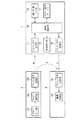
図1において、コントロール機器1とターゲット機器2とからなる制御システムの概略構成を示す。上記制御システムを構成するターゲット機器2は、リモコンによる遠隔操作が可能であり、リモコン信号を受信するための受信手段を有しているものとする。このため、ターゲット機器2は、該ターゲット機器2に付随するリモコン3を有しているものとする。尚、図1においては、説明を簡単にするため、コントロール機器1およびターゲット機器2を1つずつ備えた制御システムを例示している。
【0040】
上記制御システムにおいては、コントロール機器1によって操作しようとするターゲット機器2を指定し、該ターゲット機器2に対する操作をコントロール機器1を介して行う。この時、コントロール機器1では制御対象として指定されたターゲット機器2を認識し、該ターゲット機器2に向けてのリモコン信号(操作コマンド)を生成して送信する。これにより、上記制御システムでは、一つのコントロール機器1によって複数のターゲット機器2を制御することができる。
【0041】
上記制御システムを形成するコントロール機器1およびターゲット機器2の構成を図1を参照して以下に説明する。
【0042】
リモコン3は、ボタン入力部31、リモコン制御部32、およびリモコン信号送信部33を備えている。
【0043】
ボタン入力部31は、通常、電源ボタンやチャンネル選択(テレビやビデオのリモコンの場合)のボタンなど複数のボタンからなる。リモコン制御部32は、ボタン入力部31からの入力が行われた場合に、入力操作されたボタンがどのボタンであるかを判断し、そのボタンに対応するリモコン信号を生成する。通常、機器メーカーおよび機器カテゴリ(テレビ、ビデオなど)が同じなら、使用されるリモコン信号は同じものである。リモコン制御部32において生成されたリモコン信号は、リモコン信号送信部33から赤外線等を使って送信される。
【0044】
上記リモコン3によってターゲット機器2を直接操作する場合、リモコン信号送信部33から送信されるリモコン信号(図1中のリモコン信号A)はターゲット機器2によって受信される。また、上記リモコン3を用いて後述の登録作業を行う場合は、リモコン信号送信部33から送信されるリモコン信号(図1中のリモコン信号B)はコントロール機器1によって受信される。
【0045】
コントロール機器1は、リモコン信号受信部11、機器制御入力部12、情報提示部13、リモコン信号テーブル14、機器制御部15、およびリモコン信号送信部16を備えている。
【0046】
リモコン信号受信部11は、リモコン3から送信されるリモコン信号Bを受信するためのもので、受信したリモコンコードは機器制御部15へ送られる。
【0047】
機器制御入力部12は、コントロール機器1の動作を指示するために、操作者が入力を行うため手段を提供するものである。その実装手段には、ボタン、タッチパネル、音声入力など種々の手段が考えられる。また、上記機器制御入力部12自体をコントロール機器用のリモコンとしてコントロール機器1の外部に設けることも可能である。この場合、コントロール機器用のリモコンからの入力信号を受信するための手段として、リモコン信号受信部11を兼用することが可能である。
【0048】
情報提示部13は、コントロール機器1から操作者への情報を伝達するためのもので、ディスプレイでの表示や音声での提示などの実装が考えられる。リモコン信号テーブル14は、種々のメーカー名や機器カテゴリ毎のリモコン信号のテーブルと絞込み検索のための検索ツリーとを格納している。機器制御部15は、コントロール機器1の動作を制御するためのものである。
【0049】
リモコン信号送信部16は、コントロール機器1を介してターゲット機器2の制御を行う場合に、リモコン信号(図1中のリモコン信号C)を送信する。
【0050】
ターゲット機器2は、少なくとも、リモコン信号受信部21および機器制御部22を備えている。リモコン信号受信部21は上記リモコン3から送信されてきたリモコン信号Aを受信し、機器制御部22はリモコン信号受信部21から渡されたリモコン信号に従ってターゲット機器2の動作を制御する。
【0051】
上記制御システムにおいては、コントロール機器1が、指定されたターゲット機器2を認識可能とするために、ターゲット機器2の登録を予め行っておく必要がある。この登録作業にかかる動作の一例を、図2に示すフローチャートを用いて以下に説明する。
【0052】
上記登録作業は、例えば、コントロール機器1の機器制御入力部12においてターゲット機器登録開始の指示が入力されることにより、コントロール機器1が登録モードに移行することによって開始される。
【0053】
登録作業が開始されると、コントロール機器1は、登録しようとするターゲット機器2を識別するために該ターゲット機器2に付随するリモコン3の特定ボタンを押すように、情報提示部13からメッセージを出力する(S1)。出力するメッセージとしては、「登録したい機器のリモコンの“電源ボタン”を押してください」といったメッセージが例として挙げられる。ここで“電源ボタン”としているのはあくまで一例であり、すべての機器カテゴリのリモコンに存在しているボタンであればターゲット機器2の識別において好適に利用可能である。または、「“入力切替ボタン”または“音量小”を押してください」というように複数のボタンを指定し、指定された中の何れかのボタンを押すように操作を促してもよい。S1にてターゲット機器2識別のボタン操作を促すと、そのボタンの入力がされるまで、コントロール機器1は受信待ち状態となる(S2)。
【0054】
リモコン3においてボタンの操作入力が行われると、そのリモコン信号がコントロール機器1のリモコン信号受信部11にて受信され、機器制御部15は受信したリモコン信号がリモコン信号テーブル14の中にあるか否かを検索する(S3)。ここで、リモコン信号テーブル14には、メーカー、機器カテゴリ、および操作内容の情報と、これらの情報に対応するリモコンコードとが対応付けられた状態で格納されている。
【0055】
上記S3の検索処理は、受信したリモコン信号のリモコンコードをリモコン信号テーブル14に格納されているリモコンコードと比較することによって行われる。この際、上記検索処理は、入力を指定したボタンに対応して操作される可能性のあるリモコン信号に限定して検索を行うようにすれば、検索に係る時間を短縮することができる。
【0056】
上記検索処理において該当するリモコンコードが見つかった場合(S4でYES)は、そのリモコンコードに対応するメーカーおよび機器カテゴリをリモコン信号テーブル14から読み出すことによってターゲット機器2のメーカーおよび機器カテゴリが特定できる。しかしながら、メーカーおよび機器カテゴリを特定するのみでは、ターゲット機器2を完全に識別できない場合があるため、ターゲット機器2を識別するためのさらなる絞込みが必要か否かが判断される(S5)。
【0057】
例えば、上記検索処理において登録しようとするターゲット機器2がA社製のVTRであることが特定されたとする。しかしながら、A社製のVTRには再生専用のものと録画再生兼用の機種があり、これらの機種で“電源ボタン”のリモコンコードが共通となっている場合には、“電源ボタン”の操作のみでは該ターゲット機器2の機種までは識別できない。このような場合には、ターゲット機器2の機種までも特定してターゲット機器2を識別するために、絞込みが必要となる。このような絞込みが必要か否かについての情報は、リモコン信号テーブル14において検索ツリーの形で持てばよい。
【0058】
ターゲット機器2を識別するための絞込みが必要であると判断された場合(S5でYES)は、この絞込みを行うためのリモコン入力が、S1とは異なるボタンの入力を促すことによって指示され(S6)、S2〜S5の処理が繰り返される。
【0059】
上記S5において絞込みが必要ないと判断された場合(S5でNO)には、S3での検索の結果、登録しようとするターゲット機器2の種類が識別されているので、識別されたターゲット機器2のメーカー名と機器カテゴリで間違いないかを確認するためのメッセージを情報提示部13から出力する(S7)。出力するメッセージとしては、「登録したい機器をA社製のVTRと認識しました。これを登録しますか?登録するなら“××ボタン”を、しないなら“△△ボタン”を押してください」といったメッセージが例として挙げられる。
【0060】
ここで、登録許可時に操作されるボタン(登録ボタン)は、例えば、“再生ボタン”など機器判別の過程では使わないが識別されたターゲット機器2のリモコン3には存在するはずのボタンを割り当てることにより、誤登録を避けることができる。すなわち、上記S1〜S6の過程における機器判別が誤っていた場合、リモコン3には“再生ボタン”が存在しないか、存在していても“再生ボタン”により出力されるリモコン信号はコントロール機器1が期待するものとは異なるためである。
【0061】
また、登録のキャンセル時に操作されるボタン(キャンセルボタン)は、“電源ボタン”など機器判別の過程で用いたボタンを割り当てることにより、確実にキャンセルを行うことができる。すなわち、キャンセルボタンとして割り当てられるボタンが機器判別の過程で用いるボタンと異なる場合、機器判別が誤っていた場合には、リモコン3においてキャンセルボタンが存在しなくなる可能性があり、この時、登録もキャンセルもできなくなるといった不具合が生じうる。これに対し、キャンセルボタンとして“電源ボタン”など機器判別の過程で用いたボタンを割り当てた場合には、機器判別を誤っていた際でも、“電源ボタン”により出力されるリモコン信号は、コントロール機器1において“電源ボタン”として認識できるはずである(“電源ボタン”が認識できなければ、S7の処理まで来られないため)ため、上記不具合を回避できる。
【0062】
また、上述のように、登録ボタンやキャンセルボタンにリモコン3のボタンを割り当てる以外に、コントロール機器1の機器制御入力部12に登録ボタンやキャンセルボタンを設け、これを操作することによって登録またはキャンセルの入力を行ってもよい。
【0063】
S7におけるメッセージ出力後は、コントロール機器1は該メッセージに対する応答の入力待ち状態となる(S8)。この時、S7において、コントロール機器1の機器制御入力部12からの入力を求めた場合は機器制御入力部12からの入力を、リモコン3のボタン入力部31からの入力を求めた場合はリモコン信号受信部11からの入力を、上記両者の何れからの入力をも許容した場合は機器制御入力部12とリモコン信号受信部11の両方からの入力を待つこととなる。
【0064】
S8において入力がなされ、その入力が登録を許可するものであれば(S9でYES)、S3での検索の結果識別された機器のメーカー名と機器カテゴリをターゲット機器2のメーカー名および機器カテゴリとして登録し(S10)、登録動作を終了する。また、S8での入力が登録をキャンセルするものであれば(S9でNO)、登録を行わずに終了する。なお、上記S7からS9は、登録前の確認を行うために存在しており、これらの処理については省略可能である。
【0065】
また、S4において、リモコン信号テーブル14の最後まで検索を行った結果、該当するリモコンコードが発見されなかった場合、その旨を示すメッセージを情報提示部13から出力して、登録動作を終了する(S11)。この時、出力するメッセージとしては、「該当するものが見つかりませんでした。登録を終了します。」などといったメッセージ例が挙げられる。
【0066】
上述のフローにて示した処理により、コントロール機器1は登録しようとするターゲット機器2のメーカー名と機器カテゴリとを識別し、登録することができる。
【0067】
ターゲット機器2の登録後は、リモコン3を用いずにコントロール機器1からターゲット機器2を制御することが可能となる。その際には、コントロール機器1の機器制御部15は、制御しようとするターゲット機器2を登録されているターゲット機器2の中から選択し、選択されたターゲット機器2のメーカー名、機器カテゴリおよび制御内容に基づいてこれに対応するリモコンコードをリモコン信号テーブル14から読み出し、該リモコンコードに基づいてリモコン信号を生成する。生成されたリモコン信号は、リモコン信号送信部16から赤外線を使ってターゲット機器2に送信される。
【0068】
以上のように、本実施の形態1に係る制御システムによれば、コントロール機器1において、従来の学習リモコンのような複雑な登録作業を必要とせず、簡易な作業にてターゲット機器2のメーカー名と機器カテゴリを識別、登録することが可能であり、コントロール機器1からターゲット機器2の制御を行うことができる。
【0069】
〔実施の形態2〕
上記実施の形態1に係る制御システムでは、コントロール機器1におけるリモコン信号テーブル14内に、登録(識別)したいターゲット機器2のリモコン信号が見つからなかった場合、登録作業を中止するようになっている。これは、例えば、登録しようとするターゲット機器2が、コントロール機器1の出荷段階で製品化されておらず、対応するリモコンコードがリモコン信号テーブル14に格納されていなかった場合などに起こりうる。このため、実施の形態1に係るコントロール機器1の構成では、新しく出てくるメーカーやカテゴリの機器には対応できないといった問題がある。
【0070】
本実施の形態2に係る制御システムは、上記問題を解決し、リモコン信号テーブル14を更新することによって、新しく出てくるメーカーやカテゴリの機器においても登録を可能とする制御システムを提案するものである。
【0071】
図3において、本実施の形態2に係る制御システムの概略構成を示す。尚、図3の制御システムにおいて、ターゲット機器2およびリモコン3の構成は、実施の形態1に示したものと同様であるので、ここでは詳細な説明を省略する。
【0072】
コントロール機器5は、リモコン信号受信部51、機器制御入力部52、情報提示部53、リモコン信号テーブル54、機器制御部55、リモコン信号送信部56、およびネットワーク接続部57を備えている。このうち、リモコン信号受信部51、機器制御入力部52、情報提示部53、およびリモコン信号送信部56の構成および動作は、実施の形態1におけるコントロール機器1と同様であるため、ここでは詳細な説明を省略する。
【0073】
コントロール機器5におけるリモコン信号テーブル54は、実施の形態1におけるリモコン信号テーブル14と同様、種々のメーカー名や機器カテゴリ毎のリモコン信号のテーブルと絞込み検索のための検索ツリーを格納している。但し、リモコン信号テーブル14とは異なり、読み出し専用ではなく、格納情報の更新が可能となっている。
【0074】
機器制御部55は、実施の形態1における機器制御部15が有する機能に加え、リモコン信号テーブル54の更新機能を有している。ネットワーク接続部57は、ネットワーク上にあるリモコン信号テーブル54を更新するための更新情報を、ネットワークにアクセスして獲得するための手段である。ネットワーク接続部57が接続するネットワークの具体例としては、電話回線、有線または無線のLANやインターネット、IEEE1394などが考えられ、これらのネットワークのうち、どれか一つだけを有していてもよいし、複数有していてもよい。
【0075】
リモコン信号テーブル54の更新時には、ネットワーク接続部57経由で更新情報にアクセスし、入手した更新情報を使って機器制御部55がリモコン信号テーブル54の更新を行う。上記更新の開始は、機器制御入力部52を使ったユーザからの指示による方法、自動的に定期更新を行う方法、検索の際にリモコン信号テーブル54内に捜しているリモコン信号が見つからなかった場合にユーザからの指示によりまたは自動的に行う方法などが考えられる。
【0076】
以上のように、本実施の形態2に係る制御システムでは、リモコン信号テーブル54の格納情報をネットワークを用いて更新することが可能であり、新しく出てくるメーカーやカテゴリの機器においても登録が可能となる。
【0077】
〔実施の形態3〕
また、上記実施の形態2のコントロール機器5を用いた場合、リモコン信号テーブル54の更新以外に、コントロール機器5において、ネットワークで接続された別の機器からターゲット機器2を制御する橋渡し(ゲートウェイ)を行うことが可能である。この場合の動作を行う制御システムの具体例を本実施の形態3において説明する。
【0078】
図4において、本実施の形態3に係る制御システムの概略構成を示す。尚、図4の制御システムにおいて、ターゲット機器2およびコントロール機器5は、実施の形態1および2に示したものと同様であるので、ここでは詳細な説明を省略する。また、コントロール機器5においては既にターゲット機器2の登録(識別)は終わっているものとし、ターゲット機器の登録のみに使用される構成については図示を省略している。また、以下の説明において、ターゲット機器2が複数存在する場合に、どのターゲット機器を制御対象にするかを選択する過程も既に済んでいるものとする。
【0079】
図4に示す制御システムにおいては、機器6がネットワークを経由してコントロール機器5と接続されている。機器6は、リモコン受信部61および機器制御部62、およびネットワーク接続部63を有しており、これらはコントロール機器5におけるリモコン信号受信部51、機器制御部55およびネットワーク接続部57と同様の機能を有する。また、機器6におけるネットワーク接続部63とコントロール機器5におけるネットワーク接続部57とがネットワークを介して接続されている。
【0080】
また、リモコン7は、機器6に付随したリモコンであり、リモコン制御部72およびリモコン信号送信部73の機能は実施の形態1および2におけるリモコン3のリモコン制御部32およびリモコン信号送信部33と同様である。但し、ボタン入力部71は、機器6以外に、ターゲット機器2を制御するモードを有するようにターゲット機器制御用ボタンを有しているものとする。
【0081】
本実施の形態3に係る制御システムでは、例えば、VTRを映像ソースとしてテレビを視聴しているユーザが、該テレビから離れた場所にあるVTRを操作するような場合を例示する。ここで、図4に示す制御システムにおいては、ターゲット機器2が映像ソースであるVTRに相当する。コントロール機器5および機器6は、ターゲット機器2からの映像および音声信号をユーザが視聴しているテレビに送信するための送信機および受信機として作用する。また、ユーザが視聴しているテレビは、図示はしていないが機器6を受信機としてこれに接続されているものとする。
【0082】
上記リモコン7のボタン入力部71において、ターゲット機器制御用ボタンが押されると、リモコン制御部72にてターゲット機器制御用のリモコン信号に変換され、リモコン信号送信部73より赤外線リモコン信号として送信される。
【0083】
この際リモコン7より送信されるリモコン信号は、機器6を制御するためのリモコン信号とは異なる信号を用い、ターゲット機器2の種類(すなわち、ターゲット機器2の種類のメーカー名や機種カテゴリ)に依存しないものである。すなわち、上記リモコン信号は、コントロール機器5において専用となるリモコン信号であり、機器6は、上記リモコン信号がコントロール機器5用の信号であることを認識することはできる。例えば、ターゲット機器2がA社製のVTRであってもB社製のDVDプレーヤーであっても、制御したい内容が再生であれば、リモコン7から送信されるリモコン信号は、再生を表す単一のものになる。
【0084】
リモコン7から送信され機器6のリモコン信号受信部61で受信された上記リモコン信号は、機器制御部62に送られる。このリモコン信号がターゲット機器制御用のリモコン信号の場合、機器制御部62にてネットワーク用のリモート機器制御用コマンド(リモート制御用コマンド)に変換され、ネットワーク接続部63よりコントロール機器5に向けて送信される。上記ネットワーク用のリモート機器制御用コマンドもターゲット機器2のメーカー名や機種カテゴリに依存しない汎用のリモート機器制御用コマンドである。
【0085】
コントロール機器5では、ネットワーク接続部57にて、機器6から送信された上記リモート機器制御用コマンドを受信すると、機器制御部55に送り、機器制御部55ではターゲット機器2の識別(登録)内容にしたがって、リモコン信号テーブル54を用い、リモート機器制御用コマンドをターゲット機器制御用のリモコン信号に変換し、リモコン信号送信部56から出力する。コントロール機器5から送信された赤外線リモコン信号は、ターゲット機器2で受信され、該ターゲット機器2の制御が行われる。
【0086】
〔実施の形態4〕
また、ネットワークで接続された別の機器からターゲット機器を制御する橋渡し(ゲートウェイ)を行う動作としては、上記実施の形態3とは異なる動作も可能である。この実施の形態3とは異なる動作を行う制御システムの具体例を本実施の形態4において説明する。
【0087】
実施の形態3に示した制御システムにおいては、図4に示すように、リモコン7、機器6、コントロール機器5、ターゲット機器2が存在しており、機器6はリモコン7の送信したリモコン信号をコントロール機器5に向けネットワークを通じて送信している(中継機能のみ)。また、コントロール機器5では機器6よりネットワークを通じて送信されてきたリモコン信号をターゲット機器2用のリモコン信号に変換後、ターゲット機器2に送信することにより(リモコン信号変換機能+中継機能)、リモコン7によるターゲット機器2の制御を実現している。
【0088】
これに対し本実施の形態4に係る制御システムは、実施の形態3と比べて機器6とコントロール機器5の役割を入れ替えたものとなっている。図5において、本実施の形態4に係る制御システムの概略構成を示す。尚、図5の制御システムにおいて、リモコン7は実施の形態3に示したものと同様であるが、該リモコン7はコントロール機器5’に付随するものである。またターゲット機器2は、実施の形態1ないし3に示したものと同様であるので、ここでは詳細な説明を省略する。
【0089】
図5に示す制御システムにおいては、コントロール機器5’がネットワークを経由して機器6’と接続されている。コントロール機器5’は、実施の形態1ないし3に示したコントロール機器5と同様の構成をしているが、本実施の形態4の場合では、リモコン信号送信部56(図示していない)は存在しなくても良い。また、既にターゲット機器2の登録(識別)は終わっているものとし、ターゲット機器の登録のみに使用される構成については図示を省略している。また、以下の説明において、ターゲット機器2が複数存在する場合に、どのターゲット機器を制御対象にするかを選択する過程も既に済んでいるものとする。
【0090】
機器6’は、機器制御部62、ネットワーク接続部63、およびリモコン信号送信部64を有しており、これらは実施の形態1ないし3に示したコントロール機器5における機器制御部55、ネットワーク接続部57、およびリモコン信号送信部56と同様の機能を有する。また、機器6’におけるネットワーク接続部63とコントロール機器5’におけるネットワーク接続部57とがネットワークを介して接続されている。
【0091】
本実施の形態4に係る制御システムでは、前記実施の形態3と同様に、VTRを映像ソースとしてテレビを視聴しているユーザが、該テレビから離れた場所にあるVTRを操作するような場合を例示する。ここで、図5に示す制御システムにおいては、ターゲット機器2が映像ソースであるVTRに相当する。機器6’およびコントロール機器5’は、ターゲット機器2からの映像および音声信号をユーザが視聴しているテレビに送信するための送信機および受信機として作用する。
【0092】
リモコン7のボタン入力部71において、ターゲット機器制御用ボタンが押されると、リモコン制御部72にてターゲット機器制御用のリモコン信号に変換され、リモコン信号送信部73より赤外線リモコン信号として送信される。このターゲット機器制御用のリモコン信号はターゲット機器2のメーカー名や機種カテゴリに依存しないものである。
【0093】
リモコン7から送信されコントロール機器5’のリモコン信号受信部51で受信された上記リモコン信号は、機器制御部55に送られる。このリモコン信号がターゲット機器制御用のリモコン信号の場合、機器制御部55にてターゲット機器2の識別(登録)内容にしたがって、リモコン信号テーブル54を用い、ターゲット機器2の制御用リモコン信号に変換され、さらにリモコン信号伝達コマンドに変換され、ネットワーク接続部57より機器6’に向けて送信される。上記リモコン信号伝達コマンドは特定の機器(本実施の形態4の場合、ターゲット機器2)制御用のリモコン信号を別の機器に伝達するためのコマンドであり、すなわち、リモコン信号伝達コマンドはターゲット機器2の制御用リモコン信号を含むものとなる。
【0094】
機器6’では、ネットワーク接続部63にて、コントロール機器5’から送信された上記リモコン信号伝達コマンドを受信すると、機器制御部62に送り、機器制御部62では上記リモコン信号伝達コマンドをターゲット機器2制御用のリモコン信号に変換し(すなわち、リモコン信号伝達コマンドに含まれるターゲット機器2制御用のリモコン信号を取り出し)、リモコン信号送信部64から出力する。機器6から送信された赤外線リモコン信号は、ターゲット機器2で受信され、該ターゲット機器2の制御が行われる。
【0095】
〔実施の形態5〕
また、ネットワークで接続された別の機器からターゲット機器を制御する橋渡し(ゲートウェイ)を行う動作としては、上記実施の形態3,4とはさらに異なる動作も可能である。この実施の形態3,4とは異なる動作を行う制御システムの具体例を本実施の形態5において説明する。
【0096】
図6において、本実施の形態5に係る制御システムの概略構成を示す。尚、図6の制御システムにおいて、リモコン7は実施の形態3および4に示したものと同様であるが、コントロール機器5”−2に付随するものである。またターゲット機器2は、実施の形態1ないし4に示したものと同様であるので、ここでは詳細な説明を省略する。
【0097】
図6に示す制御システムにおいては、コントロール機器5”−2がネットワークを経由して別のコントロール機器5”−1と接続されている。コントロール機器5”−1および5”−2は、実施の形態1ないし3に示したコントロール機器5と同様の構成をしているが、本実施の形態の場合は、コントロール機器5”−2にはリモコン信号送信部56(図示していない)は存在しなくても良い。また、既にコントロール機器5”−1へのターゲット機器2の登録(識別)は終わっているものとし、ターゲット機器の登録のみに使用される構成については図示を省略している。また、以下の説明において、ターゲット機器2が複数存在する場合に、どのターゲット機器を制御対象にするかを選択する過程も既に済んでいるものとする。
【0098】
本実施の形態5に係る制御システムでは、前記実施の形態3および4と同様に、VTRを映像ソースとしてテレビを視聴しているユーザが、該テレビから離れた場所にあるVTRを操作するような場合を例示する。ここで、図6に示す制御システムにおいては、ターゲット機器2が映像ソースであるVTRに相当する。コントロール機器5”−1およびコントロール機器5”−2は、ターゲット機器2からの映像および音声信号をユーザが視聴しているテレビに送信するための送信機および受信機として作用する。
【0099】
リモコン7のボタン入力部71において、ターゲット機器制御用ボタンが押さえると、リモコン制御部72にてターゲット機器制御用のリモコン信号に変換され、リモコン信号送信部73より赤外線リモコン信号として送信される。このターゲット機器制御用のリモコン信号はターゲット機器2のメーカー名や機種カテゴリに依存しないものである。
【0100】
リモコン7から送信されコントロール機器5”−2のリモコン信号受信部51で受信された上記リモコン信号は、機器制御部55−2に送られる。このリモコン信号がターゲット機器制御用のリモコン信号の場合、機器制御部55−2にてターゲット機器2の制御用リモコン信号に変換処理が行われる。上記変換処理を行うためには、コントロール機器5”−1の機器制御部55−1が識別(登録)しているターゲット機器2のメーカー名や機種カテゴリをコントロール機器5”−2の機器制御部55−2が知る必要があるが、その方法については、後述する。
【0101】
コントロール機器5”−2の機器制御部55−2は、ターゲット機器2のメーカー名や機種カテゴリにしたがって、リモコン信号テーブル54を用い、ターゲット機器2の制御用リモコン信号に変換し、さらにリモコン信号伝達コマンドに変換される。このリモコン信号伝達コマンドは、コントロール機器5”−2のネットワーク接続部57からコントロール機器5”−1に向けて送信される。上記リモコン信号伝達コマンドは特定の機器(本実施の形態5の場合ターゲット機器2)制御用のリモコン信号を別の機器に伝達するためのコマンドであり、すなわち、リモコン信号伝達コマンドはターゲット機器2の制御用リモコン信号を含むものとなる。
【0102】
コントロール機器5”−1では、ネットワーク接続部57にて、コントロール機器5”−2から送信された上記リモコン信号伝達コマンドを受信すると、機器制御部55−1に送り、機器制御部55−1では上記リモコン信号伝達コマンドをターゲット機器2制御用のリモコン信号に変換し(すなわち、リモコン信号伝達コマンドに含まれるターゲット機器2制御用のリモコン信号を取り出し)、リモコン信号送信部56から出力する。コントロール機器5”−1から送信された赤外線リモコン信号は、ターゲット機器2で受信され、該ターゲット機器2の制御が行われる。
【0103】
ここで、上記のコントロール機器5”−1の機器制御部55−1が識別(登録)しているターゲット機器2のメーカー名や機種カテゴリをコントロール機器5”−2の機器制御部55−2が知る方法には、大きく分けて以下の二つの方法がある。
【0104】
第1の方法は、コントロール機器5”−2がコントロール機器5”−1に問い合わせをする方法で、コントロール機器5”−2の機器制御部55−2でターゲット機器2のメーカー名や機種カテゴリを知る必要が生じると、ターゲット機器問い合わせコマンドを生成し、このターゲット機器問い合わせコマンドがネットワーク接続部57よりコントロール機器5”−1に向けて送信される。
【0105】
コントロール機器5”−1では、ネットワーク接続部57にて、コントロール機器5”−2から送信された上記ターゲット機器問い合わせコマンドを受信すると、機器制御部55−1に送り、機器制御部55−1では上記ターゲット機器問い合わせコマンドを受け取ると、識別(登録)しているターゲット機器2のメーカー名や機種カテゴリの情報を含むターゲット機器回答コマンドを生成する。このターゲット機器回答コマンドは、ネットワーク接続部57よりコントロール機器5”−2に向けて送信される。
【0106】
コントロール機器5”−2では、ネットワーク接続部57にて、コントロール機器5”−1から送信された上記ターゲット機器回答コマンドを受信すると、機器制御部55−2に送り、機器制御部55−2では上記ターゲット機器回答コマンドを解釈することによりターゲット機器2のメーカー名や機種カテゴリを知ることができる。
【0107】
コントロール機器5”−2は、ターゲット機器2のメーカー名や機種カテゴリを知る必要がある度にターゲット機器問い合わせコマンドを送信しても良いし、問い合わせた結果を記憶しておいてその結果を使用しても良い。
【0108】
第2の方法は、コントロール機器5”−1が自発的にターゲット機器2のメーカー名や機種カテゴリの情報をコントロール機器5”−1に通知する方法で、コントロール機器5”−1でターゲット機器2が識別(登録)されると、コントロール機器5”−1の機器制御部55−1でターゲット機器2のメーカー名や機種カテゴリの情報を含むターゲット機器情報コマンドを生成する。このターゲット機器情報コマンドは、ネットワーク接続部57よりコントロール機器5”−2に向けて送信される。
【0109】
コントロール機器5”−2では、ネットワーク接続部57にて、コントロール機器5”−1から送信された上記ターゲット機器情報コマンドを受信すると、機器制御部55−2に送り、機器制御部55−2では上記ターゲット機器回答コマンドを解釈することによりターゲット機器2のメーカー名や機種カテゴリを知ることができ、このターゲット機器2についての情報を記憶しておくことにより、必要な時に使うことが出来る。
【0110】
コントロール機器5”−1が上記ターゲット機器情報コマンドを送信するのは、ターゲット機器2が識別(登録)された時だけでなく、識別(登録)後は定期的に送信することが望ましい。また、ターゲット機器情報コマンドは特定のコントロール機器(本実施の形態5の場合、コントロール機器5”−2)だけに向けたユニキャストではなく、ネットワーク接続部57を通じてつながっている複数のコントロール機器に向けたマルチキャストやネットワーク上のすべてのコントロール機器に向けたブロードキャストを使って送信しても良い。
【0111】
また、上記第1および第2の方法は併用可能であり、併用する場合、第1の方法で記したターゲット機器回答コマンドと第2の方法で記したターゲット機器情報コマンドとは同じものでも良い。
【0112】
また、コントロール機器5”−1における機器制御部55−1とコントロール機器5”−2における機器制御部55−2とは、互いの機能を有していてもよい。
【0113】
以下の記述は、実施の形態3ないし5に共通する内容であり、以下実施の形態3の場合を例示するが、実施の形態4および5の場合も同様のことが言える。
【0114】
上記図4に示す構成の制御システムは、例えば、据置型の映像ソース機器と持ち運びが可能なテレビとからなるような無線AV伝送システムにおいて好適に使用できる。すなわち、ユーザがテレビを映像ソース機器から離れた場所(家の中でも外でもよい)に持ち運んで見ようとする場合に、受信機となる機器6とリモコン7とをテレビと共に持っていけば、機器6とコントロール機器5とを介して映像ソース機器であるターゲット機器2を制御することができる。尚、受信機となる機器6は、テレビに対し簡易に取り付けられるような小型の機器であることが好ましく、そのような機器として提供することは容易である。
【0115】
また、この時、映像ソース機器であるターゲット機器2からテレビに対して送信される映像および音声信号も、コントロール機器5と機器6とを介して送信される。すなわち、図示はしていないが、コントロール機器5は映像および音声信号のための入力手段を有しており、ターゲット機器2の出力される映像および音声信号はコントロール機器5に取り込まれて、ネットワーク接続部57およびネットワーク接続部63を介して機器6へ送信される。一方、機器6は映像および音声信号のための出力手段を有しており、該映像および音声信号は機器6からこれに接続されたテレビに送信される。
【0116】
上述のAVシステムにおいては、ターゲット機器2としてVTR以外にDVDプレーヤーやBSまたはCSチューナーなど様々な機器が考えられるが、複数のターゲット機器2が接続される場合にも、実施の形態1または2の登録作業によって登録を行えば、1台のコントロール機器5によってこれら複数のターゲット機器2を制御することが可能である。
【0117】
また、本実施の形態3では、ターゲット機器2を制御するための大元の信号が機器6のリモコン7内のボタン入力部71から入力されているが、機器6内の機器制御入力部(図4では省略)から入力されるものであってもよい。
【0118】
以上の構成により、ネットワークに接続されていないターゲット機器2を機器6をゲートウェイにすることにより制御可能である。またその際、制御元のリモコン7ではターゲット機器2のメーカー名や機器カテゴリを意識せずに制御することが可能である。
【0119】
尚、本実施の形態3ないし5において、ネットワーク接続部57(またはネットワーク接続部63)は、上述のようなネットワークで接続された別の機器からターゲット機器2を制御する橋渡し(ゲートウェイ)機能のみを有していてもよく、あるいは、実施の形態2で示したようなリモコン信号テーブル54の更新機能と上記橋渡し(ゲートウェイ)機能との両方の機能を有していてもよい。
【0120】
上記の実施の形態1ないし5では、各リモコン信号を赤外線によるものとしているが、これは、現在主流の方式を例示しただけであり、電波などの他の無線手段や電線、光ファイバー等による有線手段を用いてもよい。
【0121】
また、上記の実施の形態1および2では、コントロール機器1におけるターゲット機器2の識別過程において、ターゲット機器2に付随したリモコン3を用いているが、このリモコン3に識別用専用ボタンを設ける構成としてもよい。この識別用専用ボタンを押されたときには、全メーカー、全機器共通のフォーマットの識別用リモコン信号が送信されるようにすると、機器制御部15での図2に示されるターゲット機器登録(識別)において、絞込みを行わなくても、最初のリモコン信号検索でターゲット機器のメーカー名、機器カテゴリを識別でき、登録作業にかかる時間を短縮することが可能である。
【0122】
尚、上記共通の識別用リモコン信号に含めるべき内容は、メーカー名、機器カテゴリ、機器型番などである。また、実施の形態2において検索したリモコン信号が見つからなかった時に、リモコン信号テーブル14を更新するためにアクセスすべき場所(URLなど)も共通の識別用リモコン信号に含めてもよい。
【0123】
【発明の効果】
本発明の制御機器は、以上のように、制御対象として登録しようとする機器のリモコンが送信するリモコン信号を受信する受信手段と、制御対象機器となる可能性がある各種機器において使用されるリモコン信号が、その機器情報と対応して格納されているリモコン信号テーブルと、受信手段によって受信したリモコン信号をリモコン信号テーブルに格納されているリモコン信号と検索し、一致したリモコン信号に対応する機器情報をリモコン信号テーブルから読み出すことによって、登録しようとする機器の種類を判別する判別手段と、判別手段によってその種類が判別された機器を制御対象機器として登録する登録手段とを有する構成である。
【0124】
それゆえ、上記登録動作を行う制御機器においては、登録しようとする機器に付随するリモコンからリモコン信号を送信するといった簡単な操作によって、制御機器は登録しようとする機器の識別を行うことができ、少ない手順で制御対象機器の登録を行うことができるといった効果を奏する。
【0125】
また、上記登録動作におい、制御対象機器に機器識別用の特別な機能の追加を要求することなく制御機器を提供できるといった効果を併せて奏する。
【0126】
また、上記制御機器は、ネットワーク経由にてリモコン信号テーブルの更新情報を獲得可能なネットワーク接続手段を有する構成とすることが好ましい。
【0127】
それゆえ、ネットワーク接続手段からネットワーク経由にてリモコン信号テーブルの更新情報を獲得することにより新しいメーカーや機器カテゴリに属する機器にも対応可能となるといった効果を奏する。
【0128】
また、上記制御機器では、ネットワークを介して他の制御機器から制御対象機器に向けた汎用のリモート制御用コマンドを受信可能なネットワーク接続手段と、ネットワーク接続手段によって他の制御機器から受信した制御対象機器に向けた汎用のリモート制御用コマンドを該制御対象機器のリモコン信号に変換する変換手段とを有する構成とすることができる。
【0129】
上記制御機器は、制御対象機器に向けた汎用のリモート制御用コマンドをネットワークを介して他の制御機器へ送信可能なネットワーク接続手段を有する制御機器とネットワークを介して接続することにより、制御対象機器をリモート制御可能なリモート制御システムを提供できる。
【0130】
それゆえ、上記制御機器をネットワークにて接続する構成において、上記制御機器をゲートウェイとして用いることでネットワークに直接は接続されていない機器を制御することができるといった効果を奏する。
【0131】
また、上記制御機器では、リモコンから受信した汎用のリモート制御要求を制御対象機器のリモコン信号に変換し、さらに該リモコン信号を含むリモコン信号伝達用コマンドに変換する変換手段と、ネットワークを介して他の制御機器へ前記リモコン信号伝達用コマンドを送信可能なネットワーク接続手段とを有する構成とすることができる。
【0132】
上記制御機器は、ネットワークを介して他の制御機器から制御対象機器に向けたリモコン信号伝達用コマンドを受信可能なネットワーク接続手段とネットワーク接続手段によって他の制御機器から受信した制御対象機器に向けたリモコン信号伝達用コマンドから該制御対象機器のリモコン信号を取り出す変換手段とを有する制御機器とネットワークを介して接続することにより、該制御対象機器をリモート制御可能なリモート制御システムを提供できる。
【0133】
それゆえ、上記制御機器をネットワークにて接続する構成において、上記制御機器をゲートウェイとして用いることでネットワークに直接は接続されていない機器を制御することができるといった効果を奏する。
【0134】
また、上記制御機器は、登録されている制御対象機器情報をネットワークを介して他の制御機器へ送信可能なネットワーク接続手段を有する構成とすることができる。
【0135】
あるいは、上記制御機器は、リモコンから受信した汎用のリモート制御要求を、他の制御機器に登録されている制御対象機器情報に基づいて制御対象機器のリモコン信号に変換し、さらに該リモコン信号を含むリモコン信号伝達用コマンドに変換する変換手段と、ネットワークを介して他の制御機器へ前記リモコン信号伝達用コマンドを送信可能なネットワーク接続手段とを有し、上記他の制御機器に登録されている制御対象機器情報は、他の制御機器からネットワークを介して上記ネットワーク接続手段により受信可能である構成とすることができる。
【0136】
上記制御機器では、当該制御機器にて実行される所定の動作時において、当該制御機器に登録されている制御対象機器情報を他の制御機器に自発的に送信する構成、あるいは、当該制御機器に登録されている制御対象機器情報の送信要求を他の制御機器から受信した場合に、該制御対象機器情報を他の制御機器に送信する構成とすることができる。
【0137】
これらの上記制御機器は、互いにネットワークを介して接続することにより、該制御対象機器をリモート制御可能なリモート制御システムを提供できる。
【0138】
それゆえ、上記制御機器をネットワークにて接続する構成において、上記制御機器をゲートウェイとして用いることでネットワークに直接は接続されていない機器を制御することができるといった効果を奏する。
【0139】
また、制御対象機器情報に基づいて汎用のリモート制御要求を制御対象機器のリモコン信号伝達用コマンドに変換する側の機器(変換側機器)では、上記変換処理を行うために、ネットワークで接続されている他方の制御機器(登録側機器)が識別(登録)している制御対象機器の情報(メーカー名や機種カテゴリ)を、ネットワークを介して知ることができるといった効果を奏する。
【0140】
本発明の制御対象機器の登録方法は、以上のように、制御対象として登録しようとする機器のリモコンが送信するリモコン信号を受信する受信ステップと、受信ステップによって受信したリモコン信号を、制御対象機器となる可能性がある各種機器において使用されるリモコン信号がその機器情報と対応して格納されているリモコン信号テーブルに対して検索する検索ステップと、リモコン信号テーブルに格納されているリモコン信号のうち、受信ステップにて受信したリモコン信号と一致するリモコン信号に対応する機器情報をリモコン信号テーブルから読み出すことによって、登録しようとする機器の種類を判別する判別ステップと、判別ステップによってその種類が判別された機器を制御対象機器として登録する登録ステップとを有する構成である。
【0141】
それゆえ、上記登録方法に従った登録を行う制御機器においては、登録しようとする機器に付随するリモコンからリモコン信号を送信するといった簡単な操作によって、制御機器は登録しようとする機器の識別を行うことができ、少ない手順で制御対象機器の登録を行うことができるといった効果を奏する。
【0142】
また、上記登録動作におい、制御対象機器に機器識別用の特別な機能の追加を要求することなく制御機器を提供できるといった効果を併せて奏する。
【0143】
また、上記制御対象機器の登録方法では、上記判別ステップにおいて、リモコン信号テーブルに格納されているリモコン信号の中に、受信ステップにて受信したリモコン信号と一致するリモコン信号がなかった場合、ネットワーク経由でリモコン信号テーブルの更新情報にアクセスし、該リモコン信号テーブルを更新した上で、再度判別ステップの処理を行う構成とすることが好ましい。
【0144】
それゆえ、ネットワーク接続手段からネットワーク経由にてリモコン信号テーブルの更新情報を獲得し、再度判別ステップを行うことにより新しいメーカーや機器カテゴリに属する機器にも対応可能となるといった効果を奏する。
【図面の簡単な説明】
【図1】本発明の実施の形態1に係る制御システムの構成を示すブロック図である。
【図2】上記制御システムにおけるターゲット機器の登録(識別)の処理に関するフローチャートである。
【図3】本発明の実施の形態2に係る制御システムの構成を示すブロック図である。
【図4】本発明の実施の形態3に係る制御システムの構成を示すブロック図である。
【図5】本発明の実施の形態4に係る制御システムの構成を示すブロック図である。
【図6】本発明の実施の形態5に係る制御システムの構成を示すブロック図である。
【符号の説明】
1,5,6 コントロール機器(制御機器)
2 ターゲット機器(制御対象機器)
3 リモコン(制御対象機器に付随するリモコン)
7 リモコン
11,51,61 リモコン信号受信部(受信手段)
14,54 リモコン信号テーブル
15,55,62 機器制御部(検索手段、判別手段、登録手段、変換手段)
57,63 ネットワーク接続部(ネットワーク接続手段)[0001]
TECHNICAL FIELD OF THE INVENTION
The present invention relates to device identification and control using a remote controller.
[0002]
[Prior art]
In recent years, digitalization and networking of home electric appliances have been advanced. In such digitalized and networked home appliances, various methods have been proposed for connecting a plurality of devices using a digital network such as IEEE 1394 and remotely controlling other devices via the digital network. Have been. However, there are still many home electric appliances which do not have a digital external interface, and remote control of such devices mainly uses remote control signals using infrared rays.
[0003]
In the case of a device operated using a remote control signal, a remote control device is usually required for each device, and it is cumbersome for the user to use the remote control device each time the device to be operated changes. Accordingly, there is a demand for a device operated by using a remote control signal to operate a plurality of devices by one control source device. At this time, whether the device to be operated (hereinafter, referred to as a control device) correctly determines the type of the device to be operated (hereinafter, referred to as a target device) whether or not the devices are connected via a digital network. Identification is necessary for correct operation.
[0004]
In the case of a device connected by a digital network, since the control device can access the target device via the network, it is easy for the control device to recognize the type of the target device. However, in the case of a device that does not have a digital external interface, some means is required for the control device to recognize the type of the target device. As means for this, for example, the following first to third means can be considered.
[0005]
As a first means, it is conceivable to provide a switch in the control device for selecting a target device to be controlled. In this case, a target device to be controlled is set in advance to each switch provided in the control device. In this configuration, the type of target device is generally set by a combination of a manufacturer name and a product category, such as a VTR (Video Tape Recorder) manufactured by Company A and a DVD (Digital Versatile Disc) player manufactured by Company B. .
[0006]
As a second means, there is a method of identifying a target device by a communication using a medium such as an infrared ray so that the target device answers an inquiry from the control device. Examples of disclosure using this method include JP-A-8-116580 and JP-A-2000-78671.
[0007]
A third means is a method of assigning a remote control code corresponding to each desired operation, such as a learning remote controller. Although this means is not strictly a means of identifying the type of the target device, the control device identifies the target device to be controlled in a pseudo manner in that a plurality of target devices can be controlled by one control device. Is considered to be
[0008]
[Problems to be solved by the invention]
However, the first means in the conventional example has a problem that the number of types of devices that can be selected is limited by the number of switches provided in advance in the control device. In addition, it is not possible to cope with a device having a new manufacturer name or category.
[0009]
In the second means, a communication (especially transmission) function is required in the target device, but a device remotely controlled by an infrared remote controller or the like usually has only a reception function and a transmission function. It is rare. Further, it is useless to add a transmission function in the target device only to inform the type of the device, and there is a problem that the second means cannot be used in a device having no transmission function.
[0010]
Further, in the third means, there is a problem that a registration work for allocating a remote control code for each operation to be performed must be performed, and the work required for the user increases, which is complicated.
[0011]
An object of the present invention is to provide an identification method and a method for registering a target device without adding a new function to the target device and capable of registering the target device with a small amount of work, which can correspond to a device of a maker name or a category which may be newly added. An object of the present invention is to provide a control device using the identification method.
[0012]
[Means for Solving the Problems]
The control device of the present invention includes a receiving unit that receives a remote control signal transmitted by a remote controller of a device to be registered as a control target and various devices that may be the control target device in order to solve the above-described problem. The remote control signal to be used is searched for the remote control signal table stored corresponding to the device information and the remote control signal received by the receiving means with the remote control signal stored in the remote control signal table. A determination unit that determines the type of the device to be registered by reading the corresponding device information from the remote control signal table; and a registration unit that registers the device whose type is determined by the determination unit as a device to be controlled. It is characterized by.
[0013]
According to the above configuration, when registering the control target device with respect to the control device, the remote control signal is transmitted from the remote control attached to the device to be registered, so that the remote control signal is received by the receiving unit of the control device. Received.
[0014]
The remote control signal received by the receiving means is searched for the remote control signal table, and the type of the device to be registered is determined by the determining means based on the search result. That is, in the remote control signal table, remote control signals used in various devices that may be control target devices are stored corresponding to the device information, and among the remote control signals stored in the remote control signal table, If there is a match with the received remote control signal, the type of the device to be registered is determined by reading the device information corresponding to the matched remote control signal from the remote control signal table.
[0015]
Further, the registration unit registers the device whose type has been determined by the determination unit as a device to be controlled, thereby completing registration of the device to be controlled.
[0016]
In the control device performing the registration operation, the control device can identify the device to be registered by a simple operation such as transmitting a remote control signal from a remote control attached to the device to be registered. The control target device can be registered. Further, in the registration operation, it is not necessary to add a special function for device identification to the device to be controlled.
[0017]
Further, it is preferable that the control device has a network connection means capable of acquiring update information of a remote control signal table via a network.
[0018]
According to the above configuration, for example, if the device to be registered belongs to a new manufacturer or device category, and there is no remote control signal that matches the remote control signal received in the remote control signal table, By acquiring the update information of the remote control signal table via the network, it becomes possible to cope with devices belonging to new manufacturers and device categories.
[0019]
Further, in the control device, a network connection unit capable of receiving a general-purpose remote control command from the other control device to the control target device via the network, and a control target received from the other control device by the network connection unit. And a conversion unit for converting a general-purpose remote control command directed to the device into a remote control signal of the control target device.
[0020]
The control device is connected to a control device having network connection means capable of transmitting a general-purpose remote control command for the control target device to another control device via a network via the network. Can provide a remote control system capable of remote control. Note that the general-purpose remote control command indicates that the remote control command does not depend on the type of the control target device (for example, a manufacturer name or a model category of the control target device).
[0021]
According to the above configuration, a remote control signal received by one control device is transmitted to another control device via the network, and the device not directly connected to the network is controlled by using the control device as a gateway. can do.
[0022]
Further, the control device converts a general-purpose remote control request received from a remote controller into a remote control signal of the device to be controlled, and further converts the request into a remote control signal transmission command including the remote control signal. Network connection means capable of transmitting the remote control signal transmission command to the control device.
[0023]
The control device includes a network connection unit capable of receiving a command for transmitting a remote control signal from another control device to the control target device via the network, and a control target device received from the other control device by the network connection unit. A remote control system capable of remotely controlling the control target device can be provided by connecting via a network to a control device having a conversion unit for extracting a remote control signal of the control target device from the remote control signal transmission command.
[0024]
According to the above configuration, a remote control signal received by one control device is transmitted to another control device via the network, and the device not directly connected to the network is controlled by using the control device as a gateway. can do.
[0025]
Further, the control device may have a network connection means capable of transmitting registered control target device information to another control device via a network.
[0026]
Alternatively, the control device converts the general-purpose remote control request received from the remote controller to a remote control signal of the control target device based on the control target device information registered in another control device, and further includes the remote control signal. A control unit that converts the command into a command for transmitting a remote control signal and a network connection unit that can transmit the command for transmitting a remote control signal to another control device via a network; The target device information can be configured to be receivable by the network connection unit from another control device via a network.
[0027]
In the above control device, at the time of a predetermined operation executed by the control device, a configuration in which control target device information registered in the control device is spontaneously transmitted to another control device, or When a transmission request for registered control target device information is received from another control device, the control target device information may be transmitted to another control device.
[0028]
By connecting these control devices to each other via a network, a remote control system capable of remotely controlling the control target device can be provided.
[0029]
According to the above configuration, a remote control signal received by one control device is transmitted to another control device via the network, and the device not directly connected to the network is controlled by using the control device as a gateway. can do.
[0030]
A device (conversion-side device) that converts a general-purpose remote control request into a command for transmitting a remote control signal of the control target device based on the control target device information is connected to a network in order to perform the conversion process. It is necessary to know information (manufacturer name and model category) of the control target device identified (registered) by the other control device (registering device). Regarding the control target device information, the registration side device spontaneously transmits the control target device information to the conversion side device, or the registration side device transmits the control target device information in accordance with the control target device information transmission request from the conversion side device. Can be transmitted to the conversion-side device.
[0031]
In order to solve the above problems, the method of registering a control target device of the present invention includes a receiving step of receiving a remote control signal transmitted by a remote control of a device to be registered as a control target, and a remote control signal received by the receiving step. A search step of searching a remote control signal table stored in correspondence with the device information for a remote control signal used in various devices that may be controlled devices, and a remote control signal stored in the remote control signal table By reading from the remote control signal table the device information corresponding to the remote control signal that matches the remote control signal received in the receiving step of the remote control signals, a determining step of determining the type of the device to be registered is performed. A registration mode for registering a device whose type has been determined as a device to be controlled It is characterized in that it has a and-up.
[0032]
According to the above configuration, when registering the control target device with respect to the control device, the remote control signal is transmitted from the remote control attached to the device to be registered, so that the remote control signal is received by the receiving unit of the control device. Received.
[0033]
The remote control signal transmitted from the remote control is received by the control device in a receiving step, and the received remote control signal is searched in a remote control signal table in a search step. In the determination step, the type of the device to be registered is determined from the search result in the search step. The device whose type is determined in the determination step is registered in the registration step as a device to be controlled.
[0034]
In a control device that performs registration according to the above registration method, the control device can identify the device to be registered by a simple operation such as transmitting a remote control signal from a remote control attached to the device to be registered. In addition, the control target device can be registered with a small number of procedures. Further, in the registration operation, it is not necessary to add a special function for device identification to the device to be controlled.
[0035]
Further, in the method of registering a control target device, in the determining step, if there is no remote control signal that matches the remote control signal received in the receiving step among the remote control signals stored in the remote control signal table, It is preferable to access the update information of the remote control signal table, update the remote control signal table, and then perform the processing of the determination step again.
[0036]
According to the above configuration, for example, if the device to be registered belongs to a new manufacturer or device category, and there is no remote control signal that matches the remote control signal received in the remote control signal table, By acquiring the update information of the remote control signal table via the network and performing the determination step again, it becomes possible to cope with devices belonging to a new manufacturer or device category.
[0037]
BEST MODE FOR CARRYING OUT THE INVENTION
[Embodiment 1]
An embodiment of the present invention will be described below with reference to FIGS.
[0038]
The present invention has been made to realize a system in which a single control source device can operate a plurality of devices as operation targets, and a control source device (control device) and an operation target device (target device). ) Is provided in the control system.
[0039]
FIG. 1 shows a schematic configuration of a control system including a
[0040]
In the control system, the
[0041]
The configuration of the
[0042]
The remote control 3 includes a
[0043]
The
[0044]
When the
[0045]
The
[0046]
The remote control
[0047]
The device
[0048]
The
[0049]
The remote control
[0050]
The
[0051]
In the above control system, it is necessary to register the
[0052]
The registration operation is started when the
[0053]
When the registration operation is started, the
[0054]
When a button operation is performed on the remote controller 3, the remote controller signal is received by the remote
[0055]
The search processing in S3 is performed by comparing the remote control code of the received remote control signal with the remote control code stored in the remote control signal table 14. At this time, if the search process is limited to a remote control signal that is likely to be operated in response to the button for which the input has been specified, the time required for the search can be reduced.
[0056]
If a corresponding remote control code is found in the above search processing (YES in S4), the maker and the device category of the
[0057]
For example, it is assumed that the
[0058]
If it is determined that narrowing down for identifying the
[0059]
If it is determined in S5 that the narrowing is not necessary (NO in S5), the type of the
[0060]
Here, a button (registration button) operated at the time of permitting registration is assigned, for example, a button such as a “play button” which is not used in the device determination process but should exist on the remote controller 3 of the identified
[0061]
Further, the button (cancel button) operated at the time of canceling the registration can be surely canceled by assigning a button such as a “power button” used in the process of device identification. That is, if the button assigned as the cancel button is different from the button used in the process of device identification, and if the device identification is incorrect, there is a possibility that the cancel button will not be present on the remote controller 3 and at this time, the registration is also canceled. May be impossible. On the other hand, if the button used in the device identification process such as the “power button” is assigned as the cancel button, the remote control signal output from the “power button” will be the control device even if the device identification is incorrect. In
[0062]
Further, as described above, in addition to assigning the buttons of the remote controller 3 to the registration button and the cancel button, a registration button and a cancel button are provided in the device
[0063]
After the message is output in S7, the
[0064]
If an input is made in S8 and the input permits registration (YES in S9), the maker name and the device category of the device identified as a result of the search in S3 are set as the maker name and the device category of the
[0065]
Further, in S4, if the corresponding remote control code is not found as a result of performing the search up to the end of the remote control signal table 14, a message to that effect is output from the
[0066]
By the processing shown in the above-mentioned flow, the
[0067]
After the registration of the
[0068]
As described above, according to the control system according to the first embodiment, the
[0069]
[Embodiment 2]
In the control system according to the first embodiment, when the remote control signal of the
[0070]
The control system according to the second embodiment proposes a control system that solves the above-described problem and enables registration of devices of newly-applied manufacturers and categories by updating the remote control signal table 14. is there.
[0071]
FIG. 3 shows a schematic configuration of a control system according to the second embodiment. In the control system shown in FIG. 3, the configurations of the
[0072]
The
[0073]
Similar to the remote control signal table 14 in the first embodiment, the remote control signal table 54 in the
[0074]
The
[0075]
When updating the remote control signal table 54, the update information is accessed via the
[0076]
As described above, in the control system according to the second embodiment, the storage information of the remote control signal table 54 can be updated using a network, and registration can be performed even for a newly-appeared manufacturer or device of a category. It becomes.
[0077]
[Embodiment 3]
When the
[0078]
FIG. 4 shows a schematic configuration of a control system according to the third embodiment. In the control system shown in FIG. 4, the
[0079]
In the control system shown in FIG. 4, the
[0080]
The
[0081]
In the control system according to the third embodiment, for example, a case where a user who is watching a television set using a VTR as a video source operates a VTR remote from the television set is exemplified. Here, in the control system shown in FIG. 4, the
[0082]
When a target device control button is pressed in the
[0083]
At this time, the remote control signal transmitted from the
[0084]
The remote control signal transmitted from the
[0085]
In the
[0086]
[Embodiment 4]
Further, as an operation of performing a bridge (gateway) for controlling the target device from another device connected via the network, an operation different from that of the third embodiment can be performed. A specific example of a control system that performs an operation different from that of the third embodiment will be described in a fourth embodiment.
[0087]
In the control system shown in the third embodiment, as shown in FIG. 4, a
[0088]
On the other hand, in the control system according to the fourth embodiment, the roles of the
[0089]
In the control system shown in FIG. 5, a control device 5 'is connected to a device 6' via a network. The control device 5 'has the same configuration as the
[0090]
The
[0091]
In the control system according to the fourth embodiment, similar to the third embodiment, it is assumed that a user who is watching a television using a VTR as a video source operates a VTR located away from the television. For example. Here, in the control system shown in FIG. 5, the
[0092]
When a target device control button is pressed in the
[0093]
The remote control signal transmitted from the
[0094]
In the
[0095]
[Embodiment 5]
Further, as an operation of performing a bridge (gateway) for controlling a target device from another device connected via a network, an operation different from those of the third and fourth embodiments can be performed. A specific example of a control system that performs an operation different from those of the third and fourth embodiments will be described in a fifth embodiment.
[0096]
FIG. 6 shows a schematic configuration of a control system according to the fifth embodiment. In the control system of Fig. 6, the
[0097]
In the control system shown in FIG. 6, a
[0098]
In the control system according to the fifth embodiment, similarly to the third and fourth embodiments, a user watching a television using a VTR as a video source operates a VTR located away from the television. A case will be exemplified. Here, in the control system shown in FIG. 6, the
[0099]
When the button for controlling the target device is pressed in the
[0100]
The remote control signal transmitted from the
[0101]
The device control unit 55-2 of the
[0102]
In the
[0103]
Here, the device control unit 55-2 of the
[0104]
The first method is a method in which the
[0105]
When the
[0106]
In the
[0107]
The
[0108]
The second method is a method in which the
[0109]
When the
[0110]
It is desirable that the
[0111]
Further, the first and second methods can be used together, and when used together, the target device response command described in the first method and the target device information command described in the second method may be the same.
[0112]
The device control unit 55-1 in the
[0113]
The following description is common to the third to fifth embodiments, and illustrates the case of the third embodiment below. The same can be said for the fourth and fifth embodiments.
[0114]
The control system having the configuration shown in FIG. 4 can be suitably used, for example, in a wireless AV transmission system including a stationary video source device and a portable television. That is, when the user carries the television to a place away from the video source device (which may be inside or outside the house) for viewing, if the user brings the
[0115]
At this time, video and audio signals transmitted from the
[0116]
In the above-described AV system, various devices such as a DVD player, a BS, or a CS tuner can be considered as the
[0117]
Further, in the third embodiment, the original signal for controlling the
[0118]
With the above configuration, the
[0119]
In the third to fifth embodiments, the network connection unit 57 (or the network connection unit 63) has only a bridging (gateway) function of controlling the
[0120]
In the first to fifth embodiments, each remote control signal is based on infrared rays. However, this is merely an example of a current mainstream system, and other wireless means such as radio waves or wired means such as electric wires or optical fibers are used. May be used.
[0121]
In the first and second embodiments, the remote controller 3 attached to the
[0122]
The contents to be included in the common identification remote control signal include a manufacturer name, a device category, and a device model number. Further, when the remote control signal searched in the second embodiment is not found, a location (URL or the like) to be accessed to update the remote control signal table 14 may be included in the common identification remote control signal.
[0123]
【The invention's effect】
As described above, the control device of the present invention includes, as described above, a receiving unit that receives a remote control signal transmitted by a remote control of a device to be registered as a control target, and a remote control used in various devices that may be the control target device. The signal is searched for a remote control signal table stored corresponding to the device information, and a remote control signal received by the receiving means is searched for a remote control signal stored in the remote control signal table, and the device information corresponding to the matched remote control signal Is read from the remote control signal table to determine the type of the device to be registered, and the registration device registers the device whose type has been determined by the determining device as a device to be controlled.
[0124]
Therefore, in the control device performing the registration operation, the control device can identify the device to be registered by a simple operation such as transmitting a remote control signal from a remote control attached to the device to be registered, There is an effect that the control target device can be registered with a small number of procedures.
[0125]
In addition, in the above-described registration operation, there is also an effect that a control device can be provided without requiring the control target device to add a special function for device identification.
[0126]
Further, it is preferable that the control device has a network connection means capable of acquiring update information of a remote control signal table via a network.
[0127]
Therefore, by acquiring the update information of the remote control signal table from the network connection means via the network, it is possible to cope with a new manufacturer or a device belonging to a device category.
[0128]
Further, in the control device, a network connection unit capable of receiving a general-purpose remote control command from the other control device to the control target device via the network, and a control target received from the other control device by the network connection unit. And a conversion unit for converting a general-purpose remote control command directed to the device into a remote control signal of the control target device.
[0129]
The control device is connected to a control device having network connection means capable of transmitting a general-purpose remote control command for the control target device to another control device via a network via the network. Can provide a remote control system capable of remote control.
[0130]
Therefore, in a configuration in which the control device is connected via a network, there is an effect that by using the control device as a gateway, a device that is not directly connected to the network can be controlled.
[0131]
Further, the control device converts a general-purpose remote control request received from a remote controller into a remote control signal of the device to be controlled, and further converts the request into a remote control signal transmission command including the remote control signal. Network connection means capable of transmitting the remote control signal transmission command to the control device.
[0132]
The control device is directed to a control target device received from another control device by a network connection unit capable of receiving a command for transmitting a remote control signal from another control device to the control target device via the network to the control target device. A remote control system capable of remotely controlling the control target device can be provided by connecting the control target device via a network to a control device having conversion means for extracting a remote control signal of the control target device from a remote control signal transmission command.
[0133]
Therefore, in a configuration in which the control device is connected via a network, there is an effect that by using the control device as a gateway, a device that is not directly connected to the network can be controlled.
[0134]
Further, the control device may have a network connection means capable of transmitting registered control target device information to another control device via a network.
[0135]
Alternatively, the control device converts the general-purpose remote control request received from the remote controller to a remote control signal of the control target device based on the control target device information registered in another control device, and further includes the remote control signal. A control unit that converts the command into a command for transmitting a remote control signal and a network connection unit that can transmit the command for transmitting a remote control signal to another control device via a network; The target device information can be configured to be receivable by the network connection unit from another control device via a network.
[0136]
In the above control device, at the time of a predetermined operation executed by the control device, a configuration in which control target device information registered in the control device is spontaneously transmitted to another control device, or When a transmission request for registered control target device information is received from another control device, the control target device information may be transmitted to another control device.
[0137]
By connecting these control devices to each other via a network, a remote control system capable of remotely controlling the control target device can be provided.
[0138]
Therefore, in a configuration in which the control device is connected via a network, there is an effect that by using the control device as a gateway, a device that is not directly connected to the network can be controlled.
[0139]
A device (conversion-side device) that converts a general-purpose remote control request into a command for transmitting a remote control signal of the control target device based on the control target device information is connected to a network in order to perform the conversion process. The information (manufacturer name and model category) of the control target device identified (registered) by the other control device (registration side device) can be known via the network.
[0140]
As described above, the method for registering a control target device of the present invention includes the steps of: receiving a remote control signal transmitted by a remote controller of a device to be registered as a control target; A search step for searching a remote control signal table stored in correspondence with the device information for a remote control signal used in various devices that may be a remote control signal among the remote control signals stored in the remote control signal table. A determination step of determining the type of the device to be registered by reading device information corresponding to the remote control signal matching the remote control signal received in the reception step from the remote control signal table; and determining the type by the determination step. Registration step of registering the device as a control target device. It is a configuration.
[0141]
Therefore, in a control device that performs registration according to the above-described registration method, the control device identifies the device to be registered by a simple operation such as transmitting a remote control signal from a remote control attached to the device to be registered. This makes it possible to register the control target device with a small number of procedures.
[0142]
In addition, in the above-described registration operation, there is also an effect that a control device can be provided without requiring the control target device to add a special function for device identification.
[0143]
Further, in the method of registering a control target device, in the determining step, if there is no remote control signal that matches the remote control signal received in the receiving step among the remote control signals stored in the remote control signal table, It is preferable to access the update information of the remote control signal table, update the remote control signal table, and then perform the processing of the determination step again.
[0144]
Therefore, by acquiring update information of the remote control signal table from the network connection means via the network and performing the determination step again, it is possible to cope with a device belonging to a new manufacturer or device category.
[Brief description of the drawings]
FIG. 1 is a block diagram showing a configuration of a control system according to
FIG. 2 is a flowchart regarding registration (identification) processing of a target device in the control system.
FIG. 3 is a block diagram showing a configuration of a control system according to
FIG. 4 is a block diagram showing a configuration of a control system according to Embodiment 3 of the present invention.
FIG. 5 is a block diagram showing a configuration of a control system according to
FIG. 6 is a block diagram showing a configuration of a control system according to
[Explanation of symbols]
1,5,6 Control equipment (control equipment)
2 Target devices (devices to be controlled)
3 Remote control (remote control attached to controlled device)
7 Remote control
11, 51, 61 remote control signal receiving section (receiving means)
14,54 remote control signal table
15, 55, 62 device control section (search means, determination means, registration means, conversion means)
57, 63 Network connection unit (network connection means)
Claims (13)
制御対象機器となる可能性がある各種機器において使用されるリモコン信号が、その機器情報と対応して格納されているリモコン信号テーブルと、
受信手段によって受信したリモコン信号をリモコン信号テーブルに格納されているリモコン信号と検索し、一致したリモコン信号に対応する機器情報をリモコン信号テーブルから読み出すことによって、登録しようとする機器の種類を判別する判別手段と、
判別手段によってその種類が判別された機器を制御対象機器として登録する登録手段とを有することを特徴とする制御機器。Receiving means for receiving a remote control signal transmitted by a remote control of a device to be registered as a control target,
A remote control signal used in various devices that may be controlled devices, a remote control signal table stored corresponding to the device information,
The type of device to be registered is determined by searching the remote control signal received by the receiving means for a remote control signal stored in the remote control signal table and reading device information corresponding to the matched remote control signal from the remote control signal table. Determining means;
Registering means for registering the device whose type has been determined by the determining device as a device to be controlled.
ネットワーク接続手段によって他の制御機器から受信した制御対象機器に向けた汎用のリモート制御用コマンドを該制御対象機器のリモコン信号に変換する変換手段とを有することを特徴とする請求項1に記載の制御機器。Network connection means capable of receiving a general-purpose remote control command directed to the control target device from another control device via a network,
2. The conversion device according to claim 1, further comprising a conversion unit configured to convert a general-purpose remote control command for the control target device received from another control device by the network connection unit into a remote control signal of the control target device. Control equipment.
ネットワークを介して他の制御機器へ前記リモコン信号伝達用コマンドを送信可能なネットワーク接続手段とを有することを特徴とする請求項1に記載の制御機器。Conversion means for converting a general-purpose remote control request received from a remote control into a remote control signal of a device to be controlled, and further converting the request into a remote control signal transmission command including the remote control signal,
2. The control device according to claim 1, further comprising: a network connection unit that can transmit the remote control signal transmission command to another control device via a network. 3.
ネットワークを介して他の制御機器へ前記リモコン信号伝達用コマンドを送信可能なネットワーク接続手段とを有し、
上記他の制御機器に登録されている制御対象機器情報は、他の制御機器からネットワークを介して上記ネットワーク接続手段により受信可能であることを特徴とする請求項1に記載の制御機器。The general-purpose remote control request received from the remote controller is converted into a remote control signal of the control target device based on the control target device information registered in another control device, and further converted into a remote control signal transmission command including the remote control signal. Means for converting
Network connection means capable of transmitting the remote control signal transmission command to another control device via a network,
The control device according to claim 1, wherein the control target device information registered in the other control device can be received from the other control device via the network by the network connection unit.
上記請求項3に記載の制御機器とをネットワークを介して接続することにより、制御対象機器をリモート制御可能なことを特徴とするリモート制御システム。A control device having network connection means capable of transmitting a general-purpose remote control command for the control target device to another control device via a network,
A remote control system, wherein the control target device can be remotely controlled by connecting the control device according to claim 3 via a network.
上記請求項4に記載の制御機器とをネットワークを介して接続することにより、該制御対象機器をリモート制御可能なことを特徴とするリモート制御システム。Network connection means capable of receiving a command for transmitting a remote control signal from another control device to a control target device via a network, and transmission of a remote control signal for the control target device received from another control device by the network connection means A control device having conversion means for extracting a remote control signal of the controlled device from the command,
5. A remote control system, wherein the control target device can be remotely controlled by connecting the control device according to claim 4 via a network.
請求項6に記載の制御機器とをネットワークを介して接続することにより、制御対象機器をリモート制御可能なことを特徴とするリモート制御システム。A control device according to claim 5,
A remote control system, wherein the control target device can be remotely controlled by connecting the control device according to claim 6 via a network.
受信ステップによって受信したリモコン信号を、制御対象機器となる可能性がある各種機器において使用されるリモコン信号がその機器情報と対応して格納されているリモコン信号テーブルに対して検索する検索ステップと、
リモコン信号テーブルに格納されているリモコン信号のうち、受信ステップにて受信したリモコン信号と一致するリモコン信号に対応する機器情報をリモコン信号テーブルから読み出すことによって、登録しようとする機器の種類を判別する判別ステップと、
判別ステップによってその種類が判別された機器を制御対象機器として登録する登録ステップとを有することを特徴とする制御対象機器の登録方法。A receiving step of receiving a remote control signal transmitted by a remote control of a device to be registered as a control target,
A remote control signal received by the receiving step, a search step of searching a remote control signal table stored in correspondence with the device information remote control signal used in various devices that may be a control target device,
The type of device to be registered is determined by reading out device information corresponding to the remote control signal that matches the remote control signal received in the receiving step from the remote control signal table among the remote control signals stored in the remote control signal table. A determining step;
Registering the device whose type has been determined by the determining step as a device to be controlled.
ネットワーク経由でリモコン信号テーブルの更新情報にアクセスし、該リモコン信号テーブルを更新した上で、再度判別ステップの処理を行うことを特徴とする請求項12に記載の制御対象機器の登録方法。In the determining step, if there is no remote control signal that matches the remote control signal received in the receiving step in the remote control signals stored in the remote control signal table,
13. The method according to claim 12, further comprising accessing the update information of the remote control signal table via a network, updating the remote control signal table, and performing the process of the determination step again.
Priority Applications (1)
| Application Number | Priority Date | Filing Date | Title |
|---|---|---|---|
| JP2003189802A JP2004088759A (en) | 2002-07-03 | 2003-07-01 | Controller, remote control system, and method for registrating apparatus to be controlled |
Applications Claiming Priority (2)
| Application Number | Priority Date | Filing Date | Title |
|---|---|---|---|
| JP2002194884 | 2002-07-03 | ||
| JP2003189802A JP2004088759A (en) | 2002-07-03 | 2003-07-01 | Controller, remote control system, and method for registrating apparatus to be controlled |
Related Child Applications (1)
| Application Number | Title | Priority Date | Filing Date |
|---|---|---|---|
| JP2007280976A Division JP4364921B2 (en) | 2002-07-03 | 2007-10-29 | Remote control system |
Publications (2)
| Publication Number | Publication Date |
|---|---|
| JP2004088759A true JP2004088759A (en) | 2004-03-18 |
| JP2004088759A5 JP2004088759A5 (en) | 2005-11-04 |
Family
ID=32071955
Family Applications (1)
| Application Number | Title | Priority Date | Filing Date |
|---|---|---|---|
| JP2003189802A Pending JP2004088759A (en) | 2002-07-03 | 2003-07-01 | Controller, remote control system, and method for registrating apparatus to be controlled |
Country Status (1)
| Country | Link |
|---|---|
| JP (1) | JP2004088759A (en) |
Cited By (6)
| Publication number | Priority date | Publication date | Assignee | Title |
|---|---|---|---|---|
| KR100693224B1 (en) | 2006-01-11 | 2007-03-13 | (주)한국무선네트워크 | A zigbee remocon |
| JP2008503982A (en) * | 2004-06-22 | 2008-02-07 | アギア システムズ インコーポレーテッド | Remote control code filtering used to relay remote control codes |
| JP2010055375A (en) * | 2008-08-28 | 2010-03-11 | Toshiba Corp | Electronic apparatus operation instruction device and operating method thereof |
| US7774509B2 (en) | 2005-03-03 | 2010-08-10 | Onkyo Corporation | Command conversion device and charging device for content reproduction device |
| JP2012150591A (en) * | 2011-01-18 | 2012-08-09 | Sumitomo Electric Networks Inc | Equipment control device and security system |
| JP5842809B2 (en) * | 2010-02-22 | 2016-01-13 | 日本電気株式会社 | Device to be controlled, device control system, device control program, and device control method |
-
2003
- 2003-07-01 JP JP2003189802A patent/JP2004088759A/en active Pending
Cited By (9)
| Publication number | Priority date | Publication date | Assignee | Title |
|---|---|---|---|---|
| JP2008503982A (en) * | 2004-06-22 | 2008-02-07 | アギア システムズ インコーポレーテッド | Remote control code filtering used to relay remote control codes |
| JP2011091867A (en) * | 2004-06-22 | 2011-05-06 | Agere Systems Inc | Remote control code filtering used for relaying of remote control code |
| JP4727661B2 (en) * | 2004-06-22 | 2011-07-20 | アギア システムズ インコーポレーテッド | Remote control code filtering used to relay remote control codes |
| KR101109826B1 (en) | 2004-06-22 | 2012-02-17 | 에이저 시스템즈 인크 | Remote control code filtering used for relaying of remote control codes |
| US7774509B2 (en) | 2005-03-03 | 2010-08-10 | Onkyo Corporation | Command conversion device and charging device for content reproduction device |
| KR100693224B1 (en) | 2006-01-11 | 2007-03-13 | (주)한국무선네트워크 | A zigbee remocon |
| JP2010055375A (en) * | 2008-08-28 | 2010-03-11 | Toshiba Corp | Electronic apparatus operation instruction device and operating method thereof |
| JP5842809B2 (en) * | 2010-02-22 | 2016-01-13 | 日本電気株式会社 | Device to be controlled, device control system, device control program, and device control method |
| JP2012150591A (en) * | 2011-01-18 | 2012-08-09 | Sumitomo Electric Networks Inc | Equipment control device and security system |
Similar Documents
| Publication | Publication Date | Title |
|---|---|---|
| US10803735B2 (en) | Agent apparatus, electrical apparatus, and method of controlling agent apparatus | |
| US8284094B2 (en) | Wireless control system | |
| US7774527B2 (en) | Apparatus and method for controlling numerous slave devices in an integrated manner | |
| JP5056373B2 (en) | Information processing apparatus and information processing method | |
| US8400344B2 (en) | Methods and apparatus for learning remote control commands | |
| US7620713B2 (en) | Device control management apparatus | |
| US8307059B2 (en) | Network system, control apparatus, terminal apparatus, and connection state determining method | |
| US20070074255A1 (en) | Signal receiver, reception signal managing method, and computer readable medium | |
| US9886844B2 (en) | Information processing apparatus, information processing method, and program | |
| JP2007507164A (en) | Apparatus control system and method and apparatus | |
| US9813753B2 (en) | Core device, audio/video control system, portable terminal device, audio/video control program, and audio/video control method | |
| WO2011038151A1 (en) | A method and system for controlling electronic devices | |
| KR20120139475A (en) | Display apparatus for setting a remote controller device and displaying method thereof | |
| CN101866541A (en) | Information communication system, messaging device, information communication program and information communicating method | |
| EP1876534B1 (en) | Control device and method, program, and recording medium | |
| JP4364921B2 (en) | Remote control system | |
| JP2004088759A (en) | Controller, remote control system, and method for registrating apparatus to be controlled | |
| JP5059775B2 (en) | Program reservation system and program reservation method | |
| KR100533676B1 (en) | Unite control device for numerous controlled device and method thereof | |
| JP4599333B2 (en) | Remote control signal receiving apparatus and control method thereof | |
| US20220353559A1 (en) | Systems and methods for controlling device configuration in a networked environment | |
| JP2010062717A (en) | Remote controller apparatus, electric device, control system and control method | |
| JP2016010051A (en) | Information setting device and information gathering system using the same | |
| KR20130014982A (en) | Method for paring in remote controllers | |
| JP2008160245A (en) | Television and data provision system |
Legal Events
| Date | Code | Title | Description |
|---|---|---|---|
| A521 | Written amendment |
Free format text: JAPANESE INTERMEDIATE CODE: A523 Effective date: 20050811 |
|
| A621 | Written request for application examination |
Free format text: JAPANESE INTERMEDIATE CODE: A621 Effective date: 20050811 |
|
| RD02 | Notification of acceptance of power of attorney |
Free format text: JAPANESE INTERMEDIATE CODE: A7422 Effective date: 20050811 |
|
| A977 | Report on retrieval |
Free format text: JAPANESE INTERMEDIATE CODE: A971007 Effective date: 20070824 |
|
| A131 | Notification of reasons for refusal |
Free format text: JAPANESE INTERMEDIATE CODE: A131 Effective date: 20070828 |
|
| A521 | Written amendment |
Free format text: JAPANESE INTERMEDIATE CODE: A523 Effective date: 20071029 |
|
| A131 | Notification of reasons for refusal |
Free format text: JAPANESE INTERMEDIATE CODE: A131 Effective date: 20090210 |
|
| A521 | Written amendment |
Free format text: JAPANESE INTERMEDIATE CODE: A523 Effective date: 20090408 |
|
| A02 | Decision of refusal |
Free format text: JAPANESE INTERMEDIATE CODE: A02 Effective date: 20090818 |