JP2004088745A - Broadcast receiving / reproducing system and broadcast receiving apparatus - Google Patents
Broadcast receiving / reproducing system and broadcast receiving apparatus Download PDFInfo
- Publication number
- JP2004088745A JP2004088745A JP2003176650A JP2003176650A JP2004088745A JP 2004088745 A JP2004088745 A JP 2004088745A JP 2003176650 A JP2003176650 A JP 2003176650A JP 2003176650 A JP2003176650 A JP 2003176650A JP 2004088745 A JP2004088745 A JP 2004088745A
- Authority
- JP
- Japan
- Prior art keywords
- broadcast receiving
- terminal
- broadcast
- signal
- data
- Prior art date
- Legal status (The legal status is an assumption and is not a legal conclusion. Google has not performed a legal analysis and makes no representation as to the accuracy of the status listed.)
- Withdrawn
Links
Images


Landscapes
- Synchronisation In Digital Transmission Systems (AREA)
Abstract
【課題】再生機能を有するホスト機器とこれに着脱可能な放送受信カードとからなる放送受信再生システムであって、放送信号中の時刻調整用信号を、伝送遅延のむらが生じないように放送受信カードからホスト機器に伝送することにより、ホスト機器での復号や再生の基準時刻となるカウンタを精度よく調整できるシステムを提供する。
【解決手段】放送受信カード100は、端子191〜194を通じてホスト機器200からのクロック信号CLKに同期してホスト機器との間で受信制御用コマンド等と応答データとの送受信を行い、カード内部で発生したクロック信号SCKに同期して放送信号からストリームデータを抽出して、クロック信号SCKとそのデータストリームとを専用の端子195〜198を通じてホスト機器へ伝送する。ホスト機器は、クロック信号SCKに同期してデータストリームから時刻調整用信号を抽出してカウンタの調整に用いる。
【選択図】 図3A broadcast reception / playback system comprising a host device having a playback function and a detachable broadcast reception card, wherein a broadcast reception card is provided for transmitting a time adjustment signal in a broadcast signal without causing transmission delay unevenness. And a system that can accurately adjust a counter serving as a reference time for decoding and reproduction in the host device by transmitting the data to the host device.
A broadcast receiving card transmits and receives a reception control command and response data to and from a host device through terminals 191 to 194 in synchronization with a clock signal CLK from the host device 200. Stream data is extracted from the broadcast signal in synchronization with the generated clock signal SCK, and the clock signal SCK and its data stream are transmitted to the host device through dedicated terminals 195 to 198. The host device extracts a time adjustment signal from the data stream in synchronization with the clock signal SCK and uses the signal for adjusting the counter.
[Selection diagram] FIG.
Description
【0001】
【発明の属する技術分野】
本発明は、デジタル放送受信再生技術に関し、特に、放送波を受信する放送受信装置をデジタルストリームの再生機器に装着して形成されるデジタル放送受信再生システムに関する。
【0002】
【従来の技術】
近年、集積回路の微細化技術の進展等を背景として、高性能な各種小型電子機器が多数開発され、急速に普及しつつある。小型電子機器としては、例えば、携帯情報端末(Personal Digital Assistance:PDA)、携帯電話機、デジタルカメラ、ノート型パソコン等がある。なお、携帯電話機等には、ビデオストリームの再生機能等を有するものもある。
【0003】
これらの小型電子機器には、メモリを増加する或いは機能を拡張するために、いわゆるメモリカードや入出力カード等の各種カード型装置を、交換装着するスロット、例えばPCカードスロット、SD(Secure Device)カードスロット等、を備えるものもある。
ここで、PCカードスロットは、PCMCIA(Personal Computer Memory Card International Association)等により策定されているPCカード規格に準拠したメモリ又はIO(Input/Output)機能を有する任意のPCカードを装着可能なスロットである。また、SDカードスロットは、デジタルカメラ等の記憶装置として普及したSD規格に準拠したSDカード、或いはSD規格を拡張し各種入出力装置の開発を可能にしたSDIO規格に準拠したSDIO(Secure Device Input/Output)カードとを装着可能なスロットである。なお、小型電子機器に着脱可能なIO装置に係る技術については、例えば特許文献1に記載されている。
【0004】
また、近年、情報通信技術の進展を背景とし、デジタル放送が実用化されており、衛星デジタル放送や地上波デジタル放送を実施している国もある。
例えば日本においては、既に衛星デジタル放送が実施されており、また、2003年末には地上波デジタル放送が開始される予定であり、上述の小型電子機器のうち携帯電話機等をターゲットとした放送も計画されている。
【0005】
以下、従来の放送受信再生装置における番組の再生タイミングの制御について説明する。
従来の一般的なデジタルテレビ放送の放送装置は、MPEG(Moving PictureExperts Group)2システム規格(ISO/IEC13818−1)に基づき、番組内容となる映像がMPEG符号化されてなるビデオストリーム、音声が符号化されてなるオーディオストリーム等を時分割多重してトランスポートストリーム(TS)の形式にして、デジタル変調して放送波として送出する。
【0006】
デジタル放送を受信する放送受信再生装置側でビデオストリームやオーディオストリームが、放送側で意図した時刻に従って正しく同期再生されることを目的として、TS内には、DTS(Decoding Time Stamp)、PTS(Presentation Time Stamp)、PCR(Program Clock Reference)という情報が含まれる。ここで、DTS及びPTSは、ビデオストリーム又はオーディオストリームのひとまとまりの単位毎について復号再生すべき時を示すタイムスタンプであり、90kHzの精度を有する。
【0007】
また、放送受信再生装置内で27MHzのクロックで計測され、MPEG復号器の復号の時刻基準を示すクロックであるSTC(System Time Clock)の値を、放送側で意図した値になるように校正するためのクロック情報がPCRである。放送側は、同様に27MHzのクロックで計測した値をPCRとして0.1ミリ秒以下の間隔でTSに多重化して放送している。なお、MPEG2システム規格においては、復号器が、PCRで示される放送側、即ち符号器側のシステムクロックと同一波形のSTCを得るために、PLL(Phase Locked Loop)機能を有すべきとされている。
【0008】
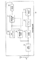
図1は、従来の放送受信再生装置の機能構成図である。
従来の放送受信再生装置90は、アンテナ91と、放送受信部92と、いわゆるTSデコーダであるストリーム処理部93と、時刻情報検出部99と、STCのカウンタである時刻カウント部96と、基準周波数制御部97と、発振器98と、ストリームバッファ94と、ストリーム再生部95とから構成される。
【0009】
放送受信部92は、チューナと復調部とを有し、チューナで同調してアンテナから受信したデジタル変調されている放送ストリームを復調し、その結果として得られるTSを、ストリーム処理部93及び時刻情報検出部99に出力する。
ストリーム処理部93は、入力されたTSを構成する各TSパケットのヘッダ解析を行い、複数のTSパケットを統合してPES(Packetized Elementary Stream)化を行い、PES化されたビデオストリーム及びオーディオストリームを、記憶領域であるストリームバッファ94に一時的に蓄積する。
【0010】
ストリームバッファ94は、ストリーム再生部の要求に応じ、PES化されたビデオストリーム及びオーディオストリームをストリーム再生部95に送出する。
ストリーム再生部95は、入力されたビデオストリーム及びオーディオストリームのPESを、PESのヘッダに付加されているDTS或いはPTSと時刻カウント部96から受け取るSTCとが等しくなったタイミングで、復号し再生する。
【0011】
時刻カウント部96は基準時間であるSTCをカウントするためのカウンタであり、発振器98(VCO:Voltage Control Oscillator)から発される27MHzを基準とする周波数のクロックに同期してカウントアップを行い、カウント値であるSTCを基準周波数制御部97とストリーム再生部95に送出する。
時刻情報検出部99は、TS中のPCRを検出し、PCRの値及びPCRの検出タイミングを基準周波数制御部97に伝える。複数バイトのデータであるPCRの最終バイトが検出されたタイミングがPCRの検出タイミングである。なお、放送側でのPCR送出タイミングと時刻情報検出部99におけるPCRの検出タイミングとは、放送経路及び受信から検出までの経路における伝送遅延により差異が生じるが、基本的に各瞬時において、差異はある程度同じであることが予定されている。
【0012】
基準周波数制御部97は、時刻情報検出部99で検出したPCRの値と時刻カウント部96からのSTCとの入力を受け、時刻情報検出部99から伝えられたPCR検出のタイミングにおいて、PCRとSTCの差を計算しD/A変換した後、ローパスフィルタをかけて得られる信号を発振器98への制御電圧として印加する。この発振器98の制御により、放送側、即ち符号器側のシステムクロックと完全に一致したSTCが時刻カウント部96からストリーム再生部95に伝達されることとなり、放送側で意図したタイミングでのビデオストリーム及びオーディオストリームの再生が実現される。
【0013】
もし、放送受信再生装置90が、TS中のPCRを検出して、これを用いてSTCの設定及び校正を実施しなければ、放送側、即ち符号器側のシステムクロックに対し、STCが進む或いは遅れるため、復号や再生を実行するタイミングにデータが完全に到着していない、或いはデータの到着に対し、復号や再生の処理が遅くてメモリがオーバーフローし、繰り返し或いはコマ落ちが発生してしまう。
【0014】
【特許文献1】
特開2001−307025号公報
【0015】
【発明が解決しようとする課題】
ところで、上述した携帯電話機等の小型電子機器により、デジタル放送を受信して再生できるようにするために、小型電子機器本体(以下、「ホスト機器」という。)に再生機能を担わせ、SDIOカードやPCカード等のホスト機器に着脱可能な小型付属装置(以下、「IOカード」という。)に放送受信機能を担わせる形態を採ることとした場合には、次の点が問題となる。
【0016】
PCカード規格或いはSDIO規格に準拠した従来のIOカードは、ホスト機器との間でデータの送受を行う場合には、ホスト機器からのクロック信号を受けて、このクロック信号に同期して、一定のフォーマットに整形したデータの送受を行っている。
この従来のIOカードと同様の方法で、放送受信機能を担うIOカードが再生機能を担うホスト機器に対して、放送信号から抽出したトランスポートストリームを一定のフォーマットに整形して断続的に伝達しただけでは、再生機器側で、再生タイミングを調整するためのSTCをトランスポートストリーム内のPCRによって正確に調整することが不可能となる。即ち、IOカードから一定のフォーマットに整形して断続的に、PCRを含むトランスポートストリームが伝送されるのであれば、PCRの受信タイミングと、再生機器側におけるPCRの検出タイミングとの差異の量が各瞬時で大きく変動し得るため、放送側で意図した通りに高い精度でSTCを調整することが不可能となる。
【0017】
そこで、本発明は、上記問題に鑑みてなされたものであり、再生機能を有するホスト機器と、ホスト機器に着脱可能な放送受信装置、つまり放送受信機能を有するIOカードとからなる放送受信再生システムであって、復号や再生の基準時刻となるSTCをある程度高い精度で調整することができる放送受信再生システムを提供すること、及びその放送受信装置を提供することを目的とする。
【0018】
【課題を解決するための手段】
上記課題を解決するために、本発明に係る放送受信装置は、機器に着脱可能であり、機器に装着されて当該機器から電力を供給されて作動する放送受信装置であって、伝送用端子と、所定周期で伝送基準クロック信号を発生する伝送基準クロック発生手段と、再生時刻調整用の情報を含むストリームデータについての放送信号を継続的に受信して、当該放送信号からストリームデータを、前記伝送基準クロック信号に同期して、抽出して前記伝送用端子を通じて前記機器へ伝送する受信伝送手段とを備えることを特徴とする。
【0019】
上記構成により、ホスト機器にセットされた放送受信装置から、ホスト機器に、一定周期のクロック信号に同期して、放送信号から抽出されたストリームデータが伝送されるため、そのストリームデータにその受信タイミングをも必要要件とする時刻制御用の情報が含まれている場合において、ホスト機器側で精度良くその時刻制御用の情報を検出することができるようになる。従って、ホスト機器は、例えばストリームデータの再生時刻を特定する基準となるホスト機器内の時計を、精度良く調整することができるようになる。
【0020】
また、本発明に係る放送受信再生システムは、再生基準クロック調整用情報及び再生時刻指定情報を含むストリームデータについての放送信号を受信する放送受信装置と、装着スロットに装着された前記放送受信装置からストリームデータを取得して再生する再生装置とを備える放送受信再生システムであって、前記放送受信装置は、伝送用端子と、所定周期で伝送基準クロック信号を発生する伝送基準クロック発生手段と、放送信号を継続的に受信して、当該放送信号からストリームデータを、前記伝送基準クロック信号に同期して、抽出して前記伝送用端子を通じて前記再生装置へ伝送する受信伝送手段とを有し、前記再生装置は、前記放送受信装置を着脱可能なスロットであり、前記伝送用端子に対応するストリームデータ端子を含む装着スロットと、前記ストリームデータ端子を通じて前記放送受信装置から伝送されるストリームデータを取得するストリームデータ取得手段と、基準周波数の再生基準クロック信号を発生し、当該再生基準クロック信号をカウントすることにより再生基準時刻を計時する再生基準時刻計時手段と、前記ストリームデータ端子を通じて、前記放送受信装置からストリームデータ中の再生基準クロック調整用情報が伝送された時と、当該再生基準クロック調整用情報の内容と、前記再生基準時刻計時手段により計時された再生基準時刻とを参照することにより、前記基準周波数を調整する再生基準クロック調整手段と、前記再生基準時刻計時手段により計時された再生基準時刻に基づき、前記ストリームデータ取得手段により取得されたストリームデータを、当該ストリームデータ中の再生時刻指定情報に応じた時刻に合わせて再生する再生手段とを有することを特徴とする。
【0021】
上記構成により、再生装置のスロットに挿入された放送受信装置から、再生装置に、一定周期のクロック信号に同期して、放送信号から抽出されたストリームデータが伝送されるため、そのストリームデータにその受信タイミングをも必要要件とする時刻制御用の情報が含まれている場合において、再生装置側で精度良くその時刻制御用の情報を検出することができるようになり、この結果として、再生装置は、ストリームデータの再生基準時刻を計時する内部時計を、精度良く調整することができ、適切な時刻にストリームデータを再生することができるようになる。
【0022】
また、本発明に係る放送受信装置は、機器に着脱可能であり、機器に装着されて作動し、機器から命令コマンドにより制御される放送受信装置であって、再生時刻調整用の情報を含むストリームデータについての放送信号を継続的に受信して、当該放送信号からストリームデータを、一定周期の伝送基準クロック信号に同期して、抽出して前記機器へ伝送する受信伝送手段を備えることを特徴とする。
【0023】
上記構成により、ホスト機器にセットされた放送受信装置から、ホスト機器に、一定周期のクロック信号に同期して、放送信号から抽出されたストリームデータが伝送されるため、そのストリームデータにその受信タイミングをも必要要件とする時刻制御用の情報が含まれている場合において、ホスト機器側で精度良くその時刻制御用の情報を検出して利用することができるようになる。
【0024】
【発明の実施の形態】
<1.実施の形態1>
以下、本発明の実施の形態1に係る放送受信再生システムについて、図面を用いて説明する。
<1−1.構成>
図2は、本発明の実施の形態1に係る放送受信再生システムの概観図である。
【0025】
放送受信再生システムは、ビデオストリーム及びオーディオストリームの再生機能を有する携帯情報端末であるホスト機器200と、放送受信カード100とから構成される。
ホスト機器200は、ディスプレイ202とPCカードスロット201を備える。また、放送受信カード100は、デジタル放送受信機能を有するPCカード型の放送受信装置であり、ホスト機器200等のPCカード型のスロットを有する機器に対して着脱可能である。図2中の矢印は、放送受信カード100が、PCカードスロット201にユーザによって挿入されることにより、ホスト機器200に装着されること示している。
【0026】
なお、放送受信カード100がホスト機器200に装着された状態において、放送受信カード100の入出力用の各端子とホスト機器200の入出力用の各端子とが整合し、その各端子を通じて、両者間でデータの送受が行われるようになる。
以下、放送受信再生システムの機能構成について説明する。
【0027】
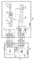
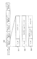
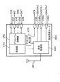
図3は、放送受信カード100及びホスト機器200の機能ブロック図である。
放送受信カード100は、MPEG2システム規格におけるTSの放送を受信する装置であり、制御部110、クロック発生部120、放送受信部130、アンテナ131及び入出力用の各端子を備える。ここで、端子には、CLK端子191、INT端子192、CMD端子193、DAT端子194、SCK端子195、SDATA端子196、PSYNC端子197、DEN端子198等がある。なお、図示しない電源端子を通じて、放送受信カード100は、ホスト機器200から電力の供給を受けて作動する。
【0028】
制御部110は、ホスト機器200からCLK端子191を通じてクロック信号(CLK)を受信し、そのクロック信号に基づくタイミングで、PCカード規格等として予め定められた規格に準拠した方式で、ホスト機器200との間で各種データの送受を行い、放送受信部130を含む放送受信カード100の各部を制御するものである。なお、その送受データには、割込信号(INT)、命令コマンド(CMD)、その他のデータ(DAT)があり、命令コマンドには、カードの機能種別を識別する機能IDを問い合わせるコマンドや、受信する周波数等を指定する受信制御に係るコマンド等が含まれる。
【0029】
クロック発生部120は、例えば2MHz等の一定周波数のクロック信号(SCK)を発生させ、そのクロック信号(SCK)を放送受信部130に伝達するとともに、そのクロック信号をSCK端子195を通じてホスト機器200へと送出するものである。
放送受信部130は、放送波からアンテナ131により受信された、デジタル変調されている放送信号を、クロック信号(SCK)に同期したタイミングで、復調してTSパケットを逐次抽出し、抽出したTSパケットをSDATA端子196を通じてホスト機器200に逐次送出する機能を有する。なお、放送受信部130は、TSパケット間にはパリティデータを埋めて送出する。更に、放送受信部130は、TSパケットの切り出し用の同期信号(PSYNC)とデータイネーブル信号(DEN)とを、それぞれPSYNC端子197、DEN端子198を通じてホスト機器200に送出する。
【0030】
また、ホスト機器200は、MPEG2システム規格におけるTSから、放送番組内容である映像や音声を抽出して再生する機能を有する装置であり、カードインタフェース(I/F)部210、ストリーム処理部220、ストリームバッファ230、ストリーム再生部240、時刻カウント部251、基準周波数制御部252、発振器253及び入出力用の各端子を備える。ここで、端子には、CLK端子291、INT端子292、CMD端子293、DAT端子294、SCK端子295、SDATA端子296、PSYNC端子297、DEN端子298等がある。
【0031】
カードI/F部210は、ホスト機器200内のCPUの制御を受けて、放送受信カード100とのデータ送受インタフェースを担い、ホスト機器200内で発生させた一定周波数のクロック信号(CLK)を放送受信カード100に伝達し、そのクロック信号(CLK)に同期したタイミングで、命令コマンドを放送受信カード100に送信し、これに付随して必要であればデータをも送信し、また放送受信カード100から命令コマンドに対応する応答データを受信する機能を有する。なお、カードI/F部210には、ホスト機器200内のCPUが、ユーザI/Fを通じて受けたユーザ操作等に応じて、命令コマンドを送出する。また、ホスト機器200内のCPUは、ホスト機器200内のメモリに格納された制御用プログラムを実行することにより各種制御動作を行うものである。
【0032】
ストリーム処理部220は、TSパケットからPCRを抽出する時刻情報検出部221を含み、SCK端子295、SDATA端子296、PSYNC端子297及びDEN端子298のそれぞれを通じて、放送受信カード100から伝送されるクロック信号(SCK)、TSパケットを含むデータ、PSYNC信号及びDEN信号を逐次受信し、PSYNC信号及びDEN信号を参照して各TSパケットを抽出し、各TSパケットのヘッダ解析を行い、複数のTSパケットを統合してPES(Packetized Elementary Stream)化を行い、PES化されたビデオストリーム及びオーディオストリームをストリームバッファ230に一時的に蓄積する機能を有する。ここで時刻情報検出部221は、TSパケットのヘッダ解析を行い、TSパケットからPCRを検出する度に、PCRの検出タイミング、即ち複数バイトのデータであるPCRの最終バイトが検出されたタイミングと、PCRの値とを基準周波数制御部252に伝える機能を有する。なお、ストリーム処理部220は、各TSパケットを放送受信カード100から受信し次第、逐次TSパケットのヘッダ解析を行うように構成されている。
【0033】
ストリームバッファ230は、メモリ領域であり、ストリーム処理部220からPES化されたビデオストリーム及びオーディオストリームを格納され、ストリーム再生部の要求に応じ、そのビデオストリーム及びオーディオストリームをストリーム再生部240に送出する機能を有する。
ストリーム再生部240は、入力されたビデオストリーム及びオーディオストリームのPESを、PESのヘッダに付加されているDTS或いはPTSと時刻カウント部251から受け取るSTCとが等しくなったタイミングで、復号し再生する機能を有する。
【0034】
時刻カウント部251は基準時間であるSTCをカウントするためのカウンタであり、発振器(VCO:Voltage Control Oscillator)253から発される27MHzを基準とする周波数のクロックに同期してカウントアップを行い、カウント値であるSTCを基準周波数制御部252とストリーム再生部240に送出する機能を有する。
【0035】
基準周波数制御部252は、時刻情報検出部221で検出したPCRの値と時刻カウント部251からのSTCとの入力を受け、時刻情報検出部221から伝えられたPCR検出のタイミングにおいて、PCRとSTCの差を計算しD/A変換した後、ローパスフィルタをかけて得られる信号を発振器253への制御電圧として印加する。この発振器253の制御により、放送側、即ち符号器側のシステムクロックと完全に一致したSTCが時刻カウント部251からストリーム再生部240に伝達されることとなり、放送側で意図したタイミングでのビデオストリーム及びオーディオストリームの再生が実現される。
【0036】
<1−2.データ>
以下、上述の放送受信再生システムにおいて扱われるデータについて説明する。
まず、放送受信再生システムにより受信される放送データについて説明する。この放送受信再生システムが受信するデジタル放送は、MPEG2システム規格、DVB−SI(Digital Video Broadcasting − Service Information)規格等に準拠したものである。
【0037】
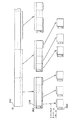
図4は、エレメンタリストリーム(ES)とTSパケットとの関係を示す図である。
ES310は、分割され、ヘッダを付加されてPES320になり、PES320は、184バイト毎に分割され、4バイトのヘッダを付加され、188バイトのTSパケット330になる。
【0038】
図5は、PESとTSとの関係を示す図である。
通常、複数の放送番組が1つのTSとして放送される。各放送番組の映像内容であるビデオストリームについてのPES及び音声内容であるオーディオストリームについてのPESは、時分割多重化され、TSを構成する。
即ち、MPEG2システム規格に準じたTSを放送する放送装置においては、映像信号又は音声信号を圧縮符号化し、独立して復号可能な単位であるアクセスユニット(AU)のデータ列である映像エレメンタリストリーム(映像ES)又は音声エレメンタリストリーム(音声ES)にし、映像ES又は音声ESをその属性を表すストリームID、復号用の時刻情報(DTS)、表示用の時刻情報(PTS)等をヘッダとして付加してパケット化することにより、パケット化された映像エレメンタリストリーム(映像PES)又はパケット化された音声エレメンタリストリーム(音声PES)を生成し、映像PES、音声PES及び他のデータ、例えばPCR339、PAT(Program Association Table)、PMT(Program Map Table)等を、時分割多重化することによりTSを生成してデジタル変調して放送として出力する。
【0039】
図6は、TSパケットのデータ構成を示す図である。
TSパケット330は、ヘッダ部分に、パケットの内容であるストリームの属性を識別するパケット識別子(PID)や、パケットがアダプテーションフィールド又はペイロード又はその両方のいずれで構成されるかを示すフラグ等を含み、形式パターン331〜333のいずれかの形式で構成される。なお、PCRは、アダプテーションフィールド内に配置される。
【0040】
次に、ホスト機器200と放送受信カード100との間で送受信されるデータについて説明する。
図7は、ホスト機器と放送受信カードとの間で送受信される命令コマンド及び応答データの構成の一例を示す図である。
同図中の「S」はスタートビット、「E」はエンドビットを表している。スタートビットとエンドビットとの間に、カードの機能IDを問い合わせる命令コマンドや、受信周波数等を指定する命令コマンド等、或いは機能IDや状態を返却する応答データ等と、CRC(Cyclic Redundancy Check)とが置かれている。
【0041】
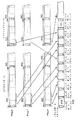
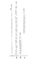
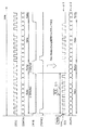
図8は、ホスト機器と放送受信カードとの間で送受信される各信号についてのタイミングチャートである。
同図では、ホスト機器200から放送受信カード100に連続的に送られるクロック(CLK)信号401と、ホスト機器200から放送受信カード100に必要時に送られる命令コマンド(CMD)信号402と、例えば命令コマンドに応答して放送受信カード100からホスト機器200に送られるデータ(DAT)信号403とを示している。
【0042】
CMD信号402とDAT信号403とは、ホスト機器200からのCLK信号401に同期して送受されるようになっている。
図9は、放送受信カード100からホスト機器200に送信される各信号についてのタイミングチャートである。
TSパケットとパリティデータとを含むデータ(SDATA)信号412は、放送受信カード100中のクロック発生部120により連続的に発され送信されるクロック(SCK)信号411に同期して、放送受信部130により送信される信号である。
【0043】
DEN信号413は、データの有効期間を示す信号、即ち、放送受信部130により、SDATA信号がTSパケットかパリティデータつまりTSパケット以外の部分かの別を示すために生成され、送出される信号である。
また、PSYNC信号414は、放送受信部130により、各TSパケット本体の先頭を送出するタイミングでのみアクティブになるように生成され、送出される信号である。
【0044】
<1−3.動作>
以下、放送受信カード100がホスト機器200に装着された状態で構成される放送受信再生システムの動作について説明する。
放送受信カード100が、ホスト機器200に装着された状態においては、CLK端子191とCLK端子291とが接続され、INT端子192とINT端子292とが接続され、CMD端子193とCMD端子293とが接続され、DAT端子194とDAT端子294とが接続され、SCK端子195とSCK端子295とが接続され、SDATA端子196とSDATA端子296とが接続され、PSYNC端子197とPSYNC端子297とが接続され、DEN端子198とDEN端子298とが接続される。
【0045】
ホスト機器200は、放送受信カード100に対してカードI/F部210から一定周波数のクロック信号(CLK)をCLK端子291を通じて送出し、例えばユーザによる放送受信再生の指示操作を検出する等に応じて、CPUによりカードI/F部210を介して、命令コマンド(CMD)をCMD端子293を通じて送信して、必要に応じて応答データ(DAT)をDAT端子294から受信して参照する。
【0046】
例えば、ホスト機器200のCPUは、カードの機能種別を問い合わせる命令コマンドを送信し、応答データを受信することにより、もしも放送受信機能を有しないPCカードがPCカードスロット201に挿入されていると判明した場合にはエラーメッセージのディスプレイ202への表示を行い、応答データにより放送受信機能を有するカードが挿入されていることが判明した場合には、ユーザ操作に応じて、受信すべき放送周波数を指定した命令コマンド等を、そのカード即ち放送受信カード100に送信する。
【0047】
一方、放送受信カード100は、ホスト機器200からの命令コマンド(CMD)に対応する制御処理を行うとともに、デジタル放送を受信する放送受信処理を行う。
図10は、放送受信カードの行う制御処理及び放送受信処理を示すフローチャートである。
【0048】
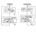
放送受信カード100の制御部110は、ホスト機器200からのクロック信号(CLK)を、CLK端子191を通じて連続的に受信し、このクロック信号に同期して命令コマンド(CMD)を、CMD端子193を通じて受信する(ステップS11)。
続いて制御部110は、命令コマンドに応じた制御を行い、その結果を示す応答データ(DAT)をDAT端子194を通じてホスト機器200に送信する(ステップS12)。このステップS11及びS12は、命令コマンド毎に繰り返し実行される。
【0049】
コマンドに応じた制御の内容は、例えば命令コマンドが受信すべき放送周波数の変更指定をしたものならば、放送受信部130を制御して受信周波数の変更を行って、変更完了の旨を示す応答データ(DAT)をDAT端子194を通じて送出するというものであり、例えば命令コマンドが機能種別を問い合わせるものならば、放送受信カード内の不揮発性メモリ部分に記録されているところの放送受信機能を有することを示す情報を応答データ(DAT)としてDAT端子194を通じて送出するというものである。なお、制御部110は、放送受信カード100において所定の割込要因の発生を検知した時には、INT端子192を通じて割込信号(INT)をホスト機器200に送信し、ホスト機器200は、その割込信号をINT端子292を通じて受信して、これに対応して予め定められている処理、例えばエラーメッセージのディスプレイへの表示処理等を行う。
【0050】
また、放送受信カード100の放送受信部130は、制御部110から制御を受けると、例えば内部のチューナに、指定された周波数の放送を受信させる等、制御に応じた動作を行い(ステップS21)、クロック発生部120の発生するクロック信号に同期し、アンテナ131を介して得られる放送受信信号から、デジタルデータ即ちTSパケットを逐次抽出して、TSパケット間にパリティデータをセットして、SDATA端子196を通じて、ホスト機器200に伝送する(ステップS22)。なお、放送受信部130は、図9に示したようにSDATA信号412、DEN信号413及びPSYNC信号414を伝送する。また、クロック発生部120の発生するクロック信号はSCK端子195を通じてホスト機器200に伝送される。
【0051】
また、このように伝送されたTSパケット群、つまりTSや、クロック信号(SCK)等は、ホスト機器200のストリーム処理部220に入力され、これを受けてストリーム処理部220は、次のストリーム処理を行う。
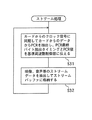
図11は、ストリーム処理部220により行われるストリーム処理を示すフローチャートである。
【0052】
ストリーム処理部220は、放送受信カード100からのクロック信号(SCK)をSCK端子295を通じて連続的に受信し、このクロック信号(SCK)に同期して、TSパケット等のデータ(SDATA)をSDATA端子296を通じて受信し、PSYNC端子297を通じて受信したPSYNC信号と、DEN端子298を通じて受信したDEN信号とを参照することにより、SDATA中のTSパケットを検出し、時刻情報検出部221において、TSパケットからPCRを検出し、TSパケット内のアダプテーションフィールド中の複数バイトからなるPCRの最終バイトを受信した時点、つまりPCRを検出したタイミングと、そのPCRを抽出して得られたPCRの値とを、基準周波数制御部252に伝える(ステップS31)。
【0053】
このPCRの検出タイミング及びPCRの値を受けて、基準周波数制御部252は時刻カウント部251によりカウントされるSTCの値を調整するための制御を行う。なお、この制御の方法は、従来と同様である。
また、ストリーム処理部220は、受信し検出した複数のTSパケットのペイロードを統合することにより、PES化されたビデオストリーム及びオーディオストリームを形成して、ストリームバッファ230に格納する(ステップS32)。
【0054】
なお、このステップS31及びS32は、繰り返し実行される。
ストリーム再生部240は、このステップS32によりストリームバッファ230に格納されたビデオストリーム及びオーディオストリームを、取得して、時刻カウント部251のカウントするSTCと、PESヘッダ内のDTS或いはPTSとの照合の上、STCとDTS又はPTSが等しくなったタイミングで、復号し再生することになる。
【0055】
即ち、ストリーム再生部240は、ビデオストリーム及びオーディオストリームにおけるAU毎に、STCを基準時間として、DTSに示される時刻に復号し、PTSに示される時刻に再生する。
<1−4.変形例>
上述の放送受信カード100では、SCK端子195、SDATA端子196、PSYNC端子197及びDEN端子198を通じて、クロック信号とTSパケット群とTSパケットの切り出しに要するデータとを一方的に伝送することとしたが、ここでは、PSYNC端子197及びDEN端子198を削除した変形例について説明する。
【0056】
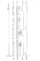
図12は、変形例における放送受信カードからホスト機器に送信されるSCK信号及びSDATA信号についてのタイミングチャートである。
なお、同図には、図9に示したタイミングチャートをも付記している。
変形例における放送受信カードでは、出力インタフェース部を設けて、その出力インタフェース部により、前述のクロック発生部120及び放送受信部130から各端子に出力されようとする信号を参照し、図12に示すようなSCK信号511をSCK端子を通じて、SDATA信号512をSDATA端子を通じて、これらの2端子のみから出力する。即ち、出力インタフェース部は、SDATA信号はそのまま出力し、また、SCK信号511として、SDATA信号がTSパケットを示している期間のみ、一定周期のクロックを表し、他の期間においては、ローレベルを連続して表すような信号を出力する。
【0057】
これにより、ホスト機器側も、PSYNC端子297及びDEN端子298を削除しておき、放送受信カードに呼応するSCK端子及びSDATA端子のみがあれば、放送から得られたデータは適切に取得できる。即ち、ホスト機器のストリーム処理部において、受信したSCK信号から、PSYNC514及びDEN513に相当する情報を得て参照することにより(図12参照)、受信したSDATA信号内のTSパケットを判別することが可能になり、PCRの検出やPES化されたビデオストリーム等のストリームバッファへの格納を行うことができる。具体的には、ホスト機器側では、SCK信号が連続したローレベルからハイレベルに切り替わった時点を、TSパケットの開始時点と判定し、SCK信号が連続したローレベルである期間以外の期間においてTSパケットが伝送されていると判定することができるため、TSパケットを判別することができる。
<2.実施の形態2>
以下、本発明の実施の形態2に係る放送受信再生システムについて説明する。
【0058】
実施の形態2に係る放送受信再生システムは、実施の形態1で示した放送受信再生システムと同様に、ホスト機器と、ホスト機器に着脱可能な放送受信カードとから構成される。但し、実施の形態2に係る放送受信再生システムは、ホスト機器と放送受信カードとの間での、ホスト機器からのクロック信号に同期した命令コマンド及びデータの送受信についてのプロトコルが相違する場合を想定したシステムである。
【0059】
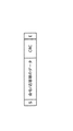
図13は、実施の形態2に係る放送受信カードの機能ブロック図である。
放送受信カード600は、MPEG2システム規格におけるTSの放送を受信する装置であり、制御部610、クロック発生部620、放送受信部630及び入出力用の各端子を備える。ここで、端子には、CLK端子691、INT端子692、CMD端子693、DAT端子694、SCK端子695、SDATA0端子696a、SDATA1端子696b、・・・、SDATA7端子696h等がある。
【0060】
なお、放送受信カード600は、実施の形態1に示した放送受信カード100と基本的に同様の機能を有している。即ち、制御部610、クロック発生部620及び放送受信部630は制御部110、クロック発生部120及び放送受信部130に相当する機能を有する。
ここでは、放送受信カード600に特有な事項について重点をおいて説明することとする。
【0061】
プロトコル変換部690は、制御部610とホスト機器との間での送受信のプロトコルが相違する場合に、その差異を吸収する機能を有する。
クロック発生部620により発生されるクロック信号の周波数は、実施の形態1のクロック発生部120により発生されるクロック信号の周波数より低く、例えば1/8である。
【0062】
放送受信部630は、実施の形態1で示した放送受信部130と同様に、クロック発生部により発生されたクロック信号に同期して、放送信号からTSパケット群を逐次抽出してそのTSパケット群等のデータを出力するのであるが、クロック発生部620から伝えられる1クロックにつき8ビット即ち1バイト分のデータを放送信号から抽出して、各ビットをSDATA0端子696a〜SDATA7端子696hを通じて伝送する。
【0063】
これにより、SCK端子695から出力されるクロック(SCK)信号における1クロックにつき、SDATA0〜7の各端子より合計1バイトのTSパケット群等のデータがホスト機器に伝送される。
従って、ホスト機器は、SCK端子から伝送されるクロック信号に同期して、SDATA0〜7の各端子から伝送されるTSパケットデータを受信し、その後は、実施の形態1で示したようにPCRの検出、STCの調整、ビデオストリーム及びオーディオストリームのDTS或いはPTSに示されたタイミングでの復号、再生等を行う。
<3.実施の形態3>
以下、本発明の実施の形態3に係る放送受信再生システムについて説明する。
【0064】
実施の形態3に係る放送受信再生システムは、実施の形態1で示した放送受信再生システムと同様に、ホスト機器と、ホスト機器に着脱可能な放送受信カードとから構成される。但し、実施の形態3に係る放送受信再生システムにおけるホスト機器は、SDカードスロットを備える携帯情報端末であり、また、放送受信カードは、SDIOカードである。
【0065】
図14は、実施の形態3に係る放送受信カードの機能ブロック図である。
放送受信カード700は、MPEG2システム規格におけるTSの放送を受信する装置たるSDIOカードであり、制御部710、クロック発生部720、放送受信部730及び入出力用の各端子を備える。ここで、端子には、SDIO規格に準拠したCLK端子791、CMD端子793、DAT0端子794、DAT1端子795、DAT2端子796等がある。
【0066】
なお、放送受信カード700は、実施の形態1に示した放送受信カード100と基本的に同様の機能を有している。即ち、制御部710、クロック発生部720及び放送受信部730は制御部110のうちINT端子に係る部分を除く部分、クロック発生部120及び放送受信部130に相当する機能を有する。
ここでは、放送受信カード700に特有な事項について重点をおいて説明することとする。
【0067】
制御部710は、ホスト機器との間で、CLK端子791を通じて受信するホスト機器からのクロック信号(CLK)に同期して、CMD端子793を通じて命令コマンドを受信し、これに応答するデータや他のデータ等をDAT0端子794を通じて送信又は受信する。制御部710は、例えば、カードの機能種別を問い合わせる命令コマンドに対して放送受信機能を有する旨の応答データを返却する。つまり、DAT0端子794を通じてのデータの送受信は、CLK端子791を通じてホスト機器から送られるクロック信号に同期して行われる。
【0068】
クロック発生部720は発生したクロック信号をDAT1端子795を通じてホスト機器に伝送する。
放送受信部730は、実施の形態1で示した放送受信部130と同様に、クロック発生部720により発生されたクロック信号に同期して、放送信号からTSパケット群を逐次抽出してそのTSパケット群等のデータをDAT2端子796を通じて、ホスト機器に伝送する。
【0069】
この放送受信カードを装着するホスト機器は、一定周期のクロック信号(CLK)をCLK端子791に与え、カードの機能種別を問い合わせる命令コマンド(CMD)や受信すべき周波数を指定する命令コマンド(CMD)等をCMD端子793に与え、カードの制御に必要なデータ(DAT0)をDAT端子794に与える又はカードからのデータ(DAT0)をDAT端子794から受信することにより、一般的なSDIOカードの制御を行う。
【0070】
更に、ホスト機器は、命令コマンドへの応答データにより、装着されているカードが放送受信機能を有する放送受信カード700であると判定した場合には、DAT1端子795からクロック信号を受信し、このクロック信号に同期してDAT2端子796からTSパケットを含むストリームデータを受信して、その後は、実施の形態1で示したようにPCRの検出、STCの調整、ビデオストリーム及びオーディオストリームのDTS或いはPTSに示されたタイミングでの復号、再生等を行う。なお、ホスト機器は、放送受信カード700以外のSDIOカードを装着している場合には、そのSDIOのDAT1端子及びDAT2端子を、必要に応じて、ホスト機器側のクロック信号に同期したデータ送受信用の経路として用いる。
<4.他の変形例>
以上、本発明に係る放送受信再生システム及び放送受信装置について、実施の形態1〜3に基づいて説明したが、本発明は、勿論これらの実施の形態に限られない。以下、実施の形態の変形に関して説明する。
(1)各実施の形態で示した放送受信カードは、内蔵アンテナ又は外部アンテナを介して放送波を受信するものとしたが、ケーブルを通じて放送信号を受信するものであってもよい。
(2)各実施の形態では、放送受信カードの受信対象となるビデオストリーム、オーディオストリーム等はMPEG2システム規格におけるTSとして多重化され放送されていることとしたが、同規格におけるプログラムストリーム(PS:Program Stream)として放送されていることとしてもよく、この場合には、放送受信カードは、内部で発生したクロックに同期して、PSをそのクロック信号とともに、SDATA端子等の専用の端子を通じてホスト機器に逐次伝送し、ホスト機器側では、PCRの代わりにPS内のパックヘッダからSCR(System Clock Reference)を検出して、STCの調整に用いる。なお、放送受信カードは、放送がMPEG2システム規格に準拠していない場合であっても、放送する信号に含まれる映像データ等の再生機能を有するホスト装置内の時計を、放送側で調整することを目的として放送する信号にその調整用のデータが含まれている場合には、放送信号を一定周期の内部クロックに基づいて専用のラインを通じてホスト機器に伝送するので有用である。
(3)各実施の形態で示した放送受信カードつまり放送受信装置は、ホスト機器のPCカードスロット或いはSDカードスロットに装着できる形状を有しており、これは従来の一般的なインタフェースを活用できる点で有用であるが、放送受信装置は、ホスト機器に着脱可能であれば、他の形状、例えば、スティック状の形状等であってもよい。着脱可能な放送受信装置は、1つのホスト機器に専用の装置ではなく、他のホスト機器に装着して利用され得るし、ホスト機器における放送受信装置を装着するためのインタフェース部分は、その形状面において、放送受信装置以外の装置、例えばメモリカード等を、装着するためにも利用され得る。
【0071】
なお、ホスト機器と、それに着脱可能な付随装置との間では、付随装置の機能動作を制御するために、命令コマンド、応答データ、制御データ等が、一定のプロトコルに従って送受信されるよう相互インタフェースが規定されるが、本発明に係る放送受信装置は、その他に、放送を受信して得られたデータを一方的にホスト機器に伝送するインタフェースを有するものであれば、物理インタフェースとなる両者の端子間は物理的に接触するのみに限られず、例えば端子間で光により伝送が行われるように構成されてもよい。
(4)放送受信カードがTSパケットをホスト機器に対して伝送するラインは、1本や8本に限定されることはなく、4本でも何本でもよい。また、TSパケットを伝送するライン毎に、1つのクロック信号を伝送するラインを設けても良い。
【0072】
また、各実施の形態ではSCK端子を通じて放送受信カードが、TSパケット群と並列にクロック信号をホスト機器に対して伝送することとしたが、これにより、放送受信カードとホスト機器との間でのデータ伝送の遅延が各瞬時においてもし小さく変動した場合であっても、ホスト機器側で精度良くPCRの受信タイミングを反映して、PCRを検出することができるようになり、精度良くSTCの調整が行える。しかし、放送受信カードがクロック信号をホスト機器に対して伝送するラインを省くこともでき、放送受信カードは、クロック信号については出力しないが、放送信号から一定周期のクロックに基づいて逐次得られたデジタルデータ、つまりTSパケット等については、そのまま専用のラインを通じてホスト機器に伝送するというようにしてもよい。この場合には、ホスト機器は内部のクロックを利用して、放送受信カードから逐次送られるTSパケットを受信しその内容を識別してPCRの検出等を行うことになる。
(5)各実施の形態では、放送受信カードは、ホスト機器から電力の供給を受けて作動することとした。これは放送受信カードの小型化に有用な面を有するが、必ずしもホスト機器から電力の供給を受ける必要はなく、外部電源又は内蔵した電池等から電力を得て作動することとしてもよい。
(6)実施の形態1では、CMD端子を通じてホスト機器から放送受信カードへの命令コマンドの送信がなされ、DAT端子は、ホスト機器に対するデータの送信とホスト機器からのデータの受信とに共用されることとしたが、放送受信カードにおける1つの端子を通じて、ホスト機器から放送受信カードへの命令コマンドの送信と、放送受信カードからのホスト機器への応答データの送信とが行われることとしてもよい。
(7)放送受信カードの放送受信部は、TSパケット間にはパリティデータを埋めて送出することとしたが、このパリティデータを、値に特段の意味のないデータ、つまりTSパケット間の時間を埋めるためのパディングデータであることとしてもよい。
【0073】
【発明の効果】
以上説明したように本発明は、機器に着脱可能であり、機器に装着されて当該機器から電力を供給されて作動する放送受信装置であって、伝送用端子と、所定周期で伝送基準クロック信号を発生する伝送基準クロック発生手段と、再生時刻調整用の情報を含むストリームデータについての放送信号を継続的に受信して、当該放送信号からストリームデータを、前記伝送基準クロック信号に同期して、抽出して前記伝送用端子を通じて前記機器へ伝送する受信伝送手段とを備えることを特徴とする。
【0074】
これにより、ホスト機器にセットされた放送受信装置から、ホスト機器に、一定周期のクロック信号に同期して、放送信号から抽出されたストリームデータが伝送されるため、そのストリームデータにその受信タイミングをも必要要件とする時刻制御用の情報が含まれている場合において、ホスト機器側で精度良くその時刻制御用の情報を検出することができるようになる。従って、ホスト機器は、例えばストリームデータの再生時刻を特定する基準となるホスト機器内の時計を、精度良く調整することができるようになる。
【0075】
ここで、前記放送受信装置は更に、伝送クロック出力端子を備え、前記伝送基準クロック発生手段は、発生した前記伝送基準クロック信号を前記伝送クロック出力端子を通じて前記機器に送信することとしてもよい。
これにより、放送受信装置から伝送されるストリームデータを受信するホスト機器は、その受信タイミングを、伝送基準クロック信号により正確に特定することができるようになるため、ストリームデータ中のPCR等の、受信タイミングの正確性が重要なデータを適切に検出できるようになる。
【0076】
また、前記放送受信装置は更に、1又は複数の通信用端子と、放送信号の選定に係る制御データを含む1以上の制御データを前記通信用端子のいずれか1以上を通じて前記機器から逐次受信し、当該制御データに対する応答データを当該通信用端子のいずれか1以上を通じて当該機器へ送信する通信手段とを備え、前記受信伝送手段の受信対象は、前記通信手段により受信されたいずれかの制御データに応じて選定される放送信号であることとしてもよい。
【0077】
これにより、受信すべき周波数の指定等の制御データや命令コマンド等をホスト機器から放送受信装置が受けて、放送受信装置からその命令コマンドに対する応答データ等を返却するという一般的な相互インタフェースを有しながら、放送受信装置は、更に放送受信で得たストリームデータを所定周波数のクロックに同期して一方的にホスト機器に伝送するので、例えば一般的なPCカードやSDIOカード等の規格にある程度適合しながらも、放送から得られたストリームデータをホスト機器に遅延の変動なく伝送する効果を有する放送受信装置が実現されることになる。
【0078】
また、前記放送受信装置は更に、制御クロック受信用端子を備え、前記通信手段は、前記制御クロック受信用端子を通じて前記機器から継続的に制御クロック信号を受信し、前記制御クロック信号に同期して、前記制御データの受信及び応答データの送信を行うこととしてもよい。
これにより、放送受信装置は、ホスト機器に装着されて作動するような付随的装置において一般的であるところの、ホスト機器からのクロック信号に同期してホスト機器との間でのデータの送受を行うようなインタフェースを有した上に、放送から得られたストリームデータを、独自の一定周期のクロックに同期して伝送するので、ホスト機器は、放送受信装置を、他の付随的装置と交換して装着した状態においては、放送されたストリームデータを、それに含まれる時刻調整用の情報を利用することにより、放送側で予定された適正な時刻に再生することができるようになる。
【0079】
また、前記受信伝送手段は、アンテナを介して前記放送信号を受信し、前記ストリームデータは、トランスポートストリームであり、前記再生時刻調整用の情報は、プログラムクロックリファレンスであることとしてもよい。
これにより、放送受信装置は、MPEG2システム規格に準拠して伝送される一般的なデジタル放送を受信して、ホスト機器に放送内容の映像データ及び音声データを適切な時刻で復号及び再生させることができるようになる。
【0080】
また、前記放送受信装置は更に、割込信号通知用端子と、所定の割込要因の発生を検知し、当該発生が検知された時に、前記割込信号通知用端子を通じて前記機器に割込信号を通知する割込通知手段とを備えることとしてもよい。
これにより、ホスト機器に着脱可能な付随的装置としての放送受信装置は、放送されたストリームデータをホスト機器に伝送する伝送路の他に、割込信号をホスト機器に通知する伝送路を有するので、ホスト機器は、割込信号を受信することにより、例えば放送受信装置において何らかのエラーが生じたこと等を検出することができるようになる。
【0081】
また、前記放送受信装置は、前記機器の有するPCカード規格に準拠したPCカードスロットに装着できる装置形状を有することとしてもよい。
これにより、この放送受信装置を装着させることにより、PCカードスロットを有し、かつストリームデータの再生機能を有するホスト機器に、放送された映像や音声を適切な時刻において再生させることができるようになる。
【0082】
また、前記放送受信装置は、前記機器の有するSDIO規格に準拠したSDカードスロットに装着できる装置形状を有することとしてもよい。
これにより、この放送受信装置を装着させることにより、SDカードスロットを有し、かつストリームデータの再生機能を有するホスト機器に、放送された映像や音声を適切な時刻において再生させることができるようになる。
【0083】
また、本発明に係る放送受信再生システムは、再生基準クロック調整用情報及び再生時刻指定情報を含むストリームデータについての放送信号を受信する放送受信装置と、装着スロットに装着された前記放送受信装置からストリームデータを取得して再生する再生装置とを備える放送受信再生システムであって、前記放送受信装置は、伝送用端子と、所定周期で伝送基準クロック信号を発生する伝送基準クロック発生手段と、放送信号を継続的に受信して、当該放送信号からストリームデータを、前記伝送基準クロック信号に同期して、抽出して前記伝送用端子を通じて前記再生装置へ伝送する受信伝送手段とを有し、前記再生装置は、前記放送受信装置を着脱可能なスロットであり、前記伝送用端子に対応するストリームデータ端子を含む装着スロットと、前記ストリームデータ端子を通じて前記放送受信装置から伝送されるストリームデータを取得するストリームデータ取得手段と、基準周波数の再生基準クロック信号を発生し、当該再生基準クロック信号をカウントすることにより再生基準時刻を計時する再生基準時刻計時手段と、前記ストリームデータ端子を通じて、前記放送受信装置からストリームデータ中の再生基準クロック調整用情報が伝送された時と、当該再生基準クロック調整用情報の内容と、前記再生基準時刻計時手段により計時された再生基準時刻とを参照することにより、前記基準周波数を調整する再生基準クロック調整手段と、前記再生基準時刻計時手段により計時された再生基準時刻に基づき、前記ストリームデータ取得手段により取得されたストリームデータを、当該ストリームデータ中の再生時刻指定情報に応じた時刻に合わせて再生する再生手段とを有することを特徴とする。
【0084】
これにより、再生装置のスロットに挿入された放送受信装置から、再生装置に、一定周期のクロック信号に同期して、放送信号から抽出されたストリームデータが伝送されるため、そのストリームデータにその受信タイミングをも必要要件とする時刻制御用の情報が含まれている場合において、再生装置側で精度良くその時刻制御用の情報を検出することができるようになり、この結果として、再生装置は、ストリームデータの再生基準時刻を計時する内部時計を、精度良く調整することができ、適切な時刻にストリームデータを再生することができるようになる。
【0085】
ここで、前記放送受信装置は、更に伝送クロック出力端子を有し、前記伝送基準クロック発生手段は、発生した前記伝送基準クロック信号を前記伝送クロック出力端子を通じて前記再生装置に送信し、前記装着スロットは、更に前記伝送クロック出力端子に対応する伝送クロック入力端子を含み、前記ストリームデータ取得手段は、前記伝送クロック入力端子を通じて伝送基準クロック信号を受信し、前記ストリームデータを当該伝送基準クロック信号に同期して取得することとしてもよい。
【0086】
これにより、放送受信装置から伝送されるストリームデータを受信する再生装置は、その受信タイミングを、伝送基準クロック信号により正確に特定することができるようになるため、例えばストリームデータ中のPCR等の、受信タイミングの正確性が重要なデータを適切に検出できるようになり、PCRを用いて再生基準時刻の計時を調整することにより、適切な時刻にストリームデータを再生することができるようになる。
【0087】
また、本発明に係る放送受信装置は、機器に着脱可能であり、機器に装着されて作動し、機器から命令コマンドにより制御される放送受信装置であって、再生時刻調整用の情報を含むストリームデータについての放送信号を継続的に受信して、当該放送信号からストリームデータを、一定周期の伝送基準クロック信号に同期して、抽出して前記機器へ伝送する受信伝送手段を備えることを特徴とする。
【0088】
これにより、ホスト機器にセットされた放送受信装置から、ホスト機器に、一定周期のクロック信号に同期して、放送信号から抽出されたストリームデータが伝送されるため、そのストリームデータにその受信タイミングをも必要要件とする時刻制御用の情報が含まれている場合において、ホスト機器側で精度良くその時刻制御用の情報を検出して利用することができるようになる。
【図面の簡単な説明】
【図1】従来の放送受信再生装置の機能構成図である。
【図2】本発明の実施の形態1に係る放送受信再生システムの概観図である。
【図3】放送受信カード及びホスト機器の機能ブロック図である。
【図4】エレメンタリストリーム(ES)とトランスポートストリーム(TS)パケットとの関係を示す図である。
【図5】パケット化されたエレメンタリストリーム(PES)とTSとの関係を示す図である。
【図6】TSパケットのデータ構成を示す図である。
【図7】ホスト機器と放送受信カードとの間で送受信される命令コマンド及び応答データの構成の一例を示す図である。
【図8】ホスト機器と放送受信カードとの間で送受信される各信号についてのタイミングチャートである。
【図9】放送受信カードからホスト機器に送信される各信号についてのタイミングチャートである。
【図10】放送受信カードの行う制御処理及び放送受信処理を示すフローチャートである。
【図11】ストリーム処理部により行われるストリーム処理を示すフローチャートである。
【図12】変形例における放送受信カードからホスト機器に送信されるクロック信号(SCK)及びデータ信号(SDATA)についてのタイミングチャートである。
【図13】本発明の実施の形態2に係る放送受信カードの機能ブロック図である。
【図14】本発明の実施の形態3に係る放送受信カードの機能ブロック図である。
【符号の説明】
100、600、700 放送受信カード
110、610、710 制御部
120、620、720 クロック発生部
130、630、730 放送受信部
131 アンテナ
191、291、691、791 CLK端子
192、292、692 INT端子
193、293、693、793 CMD端子
194、294、694、794 DAT端子
195、295、695 SCK端子
196、296 SDATA端子
197、297 PSYNC端子
198、298 DEN端子
200 ホスト機器
201 PCカードスロット
202 ディスプレイ
210 カードI/F部
220 ストリーム処理部
221 時刻情報検出部
230 ストリームバッファ
240 ストリーム再生部
251 時刻カウント部
252 基準周波数制御部
253 発振器
690 プロトコル変換部
696a〜696h SDATA0〜7端子
795 DAT1端子
796 DAT2端子[0001]
TECHNICAL FIELD OF THE INVENTION
The present invention relates to a digital broadcast receiving / reproducing technique, and more particularly, to a digital broadcast receiving / reproducing system formed by mounting a broadcast receiving apparatus for receiving broadcast waves to a digital stream reproducing apparatus.
[0002]
[Prior art]
2. Description of the Related Art In recent years, with the background of advances in the miniaturization technology of integrated circuits and the like, many high-performance various small electronic devices have been developed and are rapidly spreading. Examples of the small electronic device include a personal digital assistant (PDA), a mobile phone, a digital camera, and a notebook computer. Some mobile phones and the like have a video stream playback function and the like.
[0003]
In order to increase the memory or expand the functions of these small electronic devices, various card-type devices such as a so-called memory card and an input / output card are exchangeably mounted in a slot, for example, a PC card slot, an SD (Secure Device). Some include a card slot or the like.
Here, the PC card slot is a slot in which a memory or an arbitrary PC card having an IO (Input / Output) function conforming to the PC card standard formulated by the PCMCIA (Personal Computer Memory Card International Association) or the like can be installed. is there. The SD card slot is an SD card (Secure Device Input) compliant with the SD standard popularized as a storage device such as a digital camera, or an SDIO (Secure Device Input) compliant with the SDIO standard that expands the SD standard and enables development of various input / output devices. / Output) slot. In addition, a technology related to an IO device that can be attached to and detached from a small electronic device is described in, for example, Patent Document 1.
[0004]
In recent years, with the progress of information and communication technology, digital broadcasting has been put into practical use, and some countries are implementing satellite digital broadcasting and terrestrial digital broadcasting.
For example, in Japan, satellite digital broadcasting has already been implemented, and terrestrial digital broadcasting is scheduled to start at the end of 2003, and broadcasting targeting mobile phones among the above-mentioned small electronic devices is also planned. Have been.
[0005]
Hereinafter, control of the reproduction timing of a program in a conventional broadcast receiving and reproducing apparatus will be described.
2. Description of the Related Art A conventional general digital television broadcast broadcasting apparatus is based on an MPEG (Moving Picture Experts Group) 2 system standard (ISO / IEC13818-1), and a video stream in which a video as a program content is MPEG-encoded and a sound is encoded. The audio stream or the like is time-division multiplexed to form a transport stream (TS), digitally modulated, and transmitted as a broadcast wave.
[0006]
For the purpose of correctly reproducing a video stream and an audio stream synchronously according to the intended time on the broadcast side on the broadcast receiving / reproducing apparatus side for receiving the digital broadcast, a TS (Decoding Time Stamp) and a PTS (Presentation) are included in the TS. Time Stamp) and PCR (Program Clock Reference) are included. Here, the DTS and the PTS are time stamps indicating when decoding and reproduction should be performed for each unit of the video stream or the audio stream, and have an accuracy of 90 kHz.
[0007]
Also, the value of the STC (System Time Clock), which is a clock measured at a clock of 27 MHz in the broadcast receiving / reproducing apparatus and indicating the time reference of the decoding of the MPEG decoder, is adjusted to the value intended on the broadcasting side. The clock information for this is PCR. On the broadcast side, similarly, a value measured with a 27 MHz clock is multiplexed into a TS at intervals of 0.1 ms or less as PCR and broadcast. In the MPEG2 system standard, a decoder must have a PLL (Phase Locked Loop) function in order to obtain an STC having the same waveform as the system clock on the broadcast side indicated by PCR, that is, the encoder side. I have.
[0008]
FIG. 1 is a functional configuration diagram of a conventional broadcast receiving and reproducing apparatus.
A conventional broadcast receiving and reproducing
[0009]
The
The
[0010]
The
The
[0011]
The
The time
[0012]
The reference
[0013]
If the broadcast receiving / reproducing
[0014]
[Patent Document 1]
JP-A-2001-307025
[0015]
[Problems to be solved by the invention]
By the way, in order to enable digital broadcasting to be received and reproduced by the small electronic device such as the above-mentioned mobile phone, the main body of the small electronic device (hereinafter referred to as “host device”) has a reproduction function, and an SDIO card is used. In the case where a small accessory device (hereinafter, referred to as an "IO card") that can be attached to and detached from a host device such as a PC or a PC card is used to perform a broadcast receiving function, the following problems arise.
[0016]
A conventional IO card conforming to the PC card standard or the SDIO standard receives a clock signal from the host device when transmitting / receiving data to / from the host device, and synchronizes with the clock signal to generate a predetermined signal. Sends and receives data formatted into a format.
In the same manner as the conventional IO card, the IO card having the broadcast receiving function formed the transport stream extracted from the broadcast signal into a certain format and transmitted it intermittently to the host device having the reproducing function. With only this, it becomes impossible for the playback device to accurately adjust the STC for adjusting the playback timing by PCR in the transport stream. That is, if a transport stream including PCR is intermittently transmitted after being formatted into a certain format from the IO card, the amount of difference between the PCR reception timing and the PCR detection timing on the playback device side is reduced. Since it can greatly fluctuate at each instant, it becomes impossible for the broadcasting side to adjust the STC with high precision as intended.
[0017]
In view of the above, the present invention has been made in view of the above problems, and has a broadcast receiving / reproducing system including a host device having a reproducing function and a broadcast receiving device detachable from the host device, that is, an IO card having a broadcast receiving function. It is an object of the present invention to provide a broadcast receiving / reproducing system capable of adjusting the STC serving as a reference time for decoding and reproducing with a high degree of accuracy, and to provide the broadcast receiving apparatus.
[0018]
[Means for Solving the Problems]
In order to solve the above problems, a broadcast receiving device according to the present invention is a broadcast receiving device that is detachable from a device and is operated by being supplied with power from the device when mounted on the device, and includes a transmission terminal and A transmission reference clock generating means for generating a transmission reference clock signal at a predetermined cycle; and continuously receiving a broadcast signal for stream data including information for adjusting reproduction time, and transmitting the stream data from the broadcast signal. Receiving transmission means for extracting and transmitting to the device through the transmission terminal in synchronization with a reference clock signal.
[0019]
According to the above configuration, since the stream data extracted from the broadcast signal is transmitted from the broadcast receiving device set in the host device to the host device in synchronization with the clock signal having a fixed period, the reception timing is added to the stream data. In the case where the information for time control, which also needs to be included, is included, the host device can accurately detect the information for time control. Therefore, the host device can accurately adjust, for example, a clock in the host device which is a reference for specifying the reproduction time of the stream data.
[0020]
Further, the broadcast receiving and reproducing system according to the present invention comprises: a broadcast receiving apparatus that receives a broadcast signal for stream data including reproduction reference clock adjustment information and reproduction time designation information; and a broadcast receiving apparatus mounted in a mounting slot. A broadcast receiving and reproducing system comprising: a reproducing device that acquires and reproduces stream data, wherein the broadcast receiving device includes a transmission terminal, a transmission reference clock generating unit that generates a transmission reference clock signal at a predetermined cycle, Receiving and transmitting means for continuously receiving a signal, extracting stream data from the broadcast signal in synchronization with the transmission reference clock signal, and extracting the extracted data and transmitting the extracted data to the playback device through the transmission terminal; The playback device is a slot to which the broadcast receiving device can be attached and detached, and includes a stream data terminal corresponding to the transmission terminal. Receiving slot, stream data obtaining means for obtaining stream data transmitted from the broadcast receiving apparatus through the stream data terminal, generating a reproduction reference clock signal of a reference frequency, and reproducing by counting the reproduction reference clock signal. Reproduction reference time clocking means for clocking a reference time; when the reproduction reference clock adjustment information in the stream data is transmitted from the broadcast receiving device through the stream data terminal; and the content of the reproduction reference clock adjustment information. By referring to the reproduction reference time measured by the reproduction reference time clocking means, a reproduction reference clock adjusting means for adjusting the reference frequency, and a reproduction reference time clocked by the reproduction reference time clocking means, The stream obtained by the stream data obtaining means The Mudeta, and having a reproducing device for reproducing in accordance with the time corresponding to the reproduction time specifying information in the stream data.
[0021]
According to the above configuration, the stream data extracted from the broadcast signal is transmitted from the broadcast receiving device inserted into the slot of the playback device to the playback device in synchronization with the clock signal having a constant period. In the case where the information for time control that also requires the reception timing is included, the information for time control can be accurately detected on the reproducing apparatus side. As a result, the reproducing apparatus In addition, the internal clock for measuring the stream data reproduction reference time can be adjusted with high accuracy, and the stream data can be reproduced at an appropriate time.
[0022]
Also, the broadcast receiving apparatus according to the present invention is a broadcast receiving apparatus that is detachable from a device, is mounted on the device and operates, and is controlled by a command from the device, and includes a stream including information for adjusting playback time. It is characterized by comprising receiving and transmitting means for continuously receiving a broadcast signal for data, extracting stream data from the broadcast signal in synchronization with a transmission reference clock signal having a fixed period, and extracting and transmitting the extracted data to the device. I do.
[0023]
According to the above configuration, since the stream data extracted from the broadcast signal is transmitted from the broadcast receiving device set in the host device to the host device in synchronization with the clock signal having a fixed period, the reception timing is added to the stream data. In the case where the information for time control, which is a necessary requirement, is included, the host device can accurately detect and use the information for time control.
[0024]
BEST MODE FOR CARRYING OUT THE INVENTION
<1. First Embodiment>
Hereinafter, a broadcast reception / playback system according to Embodiment 1 of the present invention will be described with reference to the drawings.
<1-1. Configuration>
FIG. 2 is an overview diagram of the broadcast reception / playback system according to Embodiment 1 of the present invention.
[0025]
The broadcast reception / playback system includes a
The
[0026]
When the
Hereinafter, a functional configuration of the broadcast reception / playback system will be described.
[0027]
FIG. 3 is a functional block diagram of the
The
[0028]
The
[0029]
The
The
[0030]
Further, the
[0031]
The card I /
[0032]
The
[0033]
The
The
[0034]
The
[0035]
The reference
[0036]
<1-2. Data>
Hereinafter, data handled in the above-described broadcast receiving and reproducing system will be described.
First, broadcast data received by the broadcast reception / playback system will be described. The digital broadcast received by the broadcast receiving and reproducing system conforms to the MPEG2 system standard, DVB-SI (Digital Video Broadcasting-Service Information) standard, and the like.
[0037]
FIG. 4 is a diagram showing a relationship between an elementary stream (ES) and TS packets.
The
[0038]
FIG. 5 is a diagram showing the relationship between PES and TS.
Usually, a plurality of broadcast programs are broadcast as one TS. The PES for the video stream that is the video content of each broadcast program and the PES for the audio stream that is the audio content are time-division multiplexed to form a TS.
That is, in a broadcasting apparatus that broadcasts a TS conforming to the MPEG2 system standard, a video elementary stream that is a data string of an access unit (AU) that is a unit that can compress and encode a video signal or an audio signal and independently decode the video signal or the audio signal. (Video ES) or audio elementary stream (audio ES), and attaches the video ES or audio ES as a header with a stream ID representing its attribute, time information for decoding (DTS), time information for display (PTS), etc. To generate a packetized video elementary stream (video PES) or a packetized audio elementary stream (audio PES), and generate video PES, audio PES and other data, for example, PCR 339, PAT (Program Association Table), PMT The Program the Map Table) or the like, and generates a TS by time division multiplexing to output as a broadcast by digital modulation.
[0039]
FIG. 6 is a diagram showing a data configuration of a TS packet.
The
[0040]
Next, data transmitted and received between the
FIG. 7 is a diagram showing an example of the configuration of a command and response data transmitted and received between the host device and the broadcast receiving card.
In the figure, "S" indicates a start bit, and "E" indicates an end bit. Between the start bit and the end bit, a command command for inquiring of a function ID of a card, a command command for specifying a reception frequency or the like, response data for returning a function ID or status, a CRC (Cyclic Redundancy Check), and the like. Is placed.
[0041]
FIG. 8 is a timing chart for signals transmitted and received between the host device and the broadcast receiving card.
In the figure, a clock (CLK) signal 401 continuously transmitted from the
[0042]
The
FIG. 9 is a timing chart of each signal transmitted from the
The data (SDATA) signal 412 including the TS packet and the parity data is synchronized with the clock (SCK) signal 411 continuously generated and transmitted by the
[0043]
The
The
[0044]
<1-3. Operation>
Hereinafter, the operation of the broadcast reception / playback system configured with the
When the
[0045]
The
[0046]
For example, the CPU of the
[0047]
On the other hand, the
FIG. 10 is a flowchart showing a control process and a broadcast receiving process performed by the broadcast receiving card.
[0048]
The
Subsequently, the
[0049]
The content of the control according to the command is, for example, if the command command specifies the change of the broadcast frequency to be received, the
[0050]
When receiving the control from the
[0051]
The group of TS packets transmitted in this manner, that is, the TS, the clock signal (SCK), and the like are input to the
FIG. 11 is a flowchart showing stream processing performed by the
[0052]
The
[0053]
In response to the PCR detection timing and the PCR value, the reference
In addition, the
[0054]
Steps S31 and S32 are repeatedly executed.
The
[0055]
That is, the
<1-4. Modification>
In the above-described
[0056]
FIG. 12 is a timing chart of the SCK signal and the SDATA signal transmitted from the broadcast receiving card to the host device in the modification.
Note that the timing chart shown in FIG. 9 is additionally shown in FIG.
In the broadcast receiving card according to the modified example, an output interface unit is provided, and the output interface unit refers to signals to be output from the
[0057]
As a result, the host device also deletes the
<2. Second Embodiment>
Hereinafter, a broadcast reception / playback system according to Embodiment 2 of the present invention will be described.
[0058]
The broadcast receiving and reproducing system according to the second embodiment includes a host device and a broadcast receiving card that can be attached to and detached from the host device, similarly to the broadcast receiving and reproducing system described in the first embodiment. However, the broadcast reception / reproduction system according to Embodiment 2 assumes a case where the protocol for transmitting and receiving the command and data synchronized with the clock signal from the host device differs between the host device and the broadcast reception card. It is a system that did.
[0059]
FIG. 13 is a functional block diagram of the broadcast receiving card according to the second embodiment.
The
[0060]
Note that
Here, matters specific to the
[0061]
The
The frequency of the clock signal generated by
[0062]
The
[0063]
Thus, for one clock of the clock (SCK) signal output from the
Accordingly, the host device receives the TS packet data transmitted from each of the SDATA0 to SDATA7 terminals in synchronization with the clock signal transmitted from the SCK terminal, and thereafter performs the PCR of the PCR as described in the first embodiment. Detection, adjustment of STC, decoding and reproduction of the video stream and audio stream at the timing indicated in the DTS or PTS are performed.
<3. Third Embodiment>
Hereinafter, a broadcast reception / playback system according to Embodiment 3 of the present invention will be described.
[0064]
The broadcast receiving and playing system according to the third embodiment includes a host device and a broadcast receiving card that can be attached to and detached from the host device, similarly to the broadcast receiving and playing system described in the first embodiment. However, the host device in the broadcast receiving and reproducing system according to the third embodiment is a portable information terminal having an SD card slot, and the broadcast receiving card is an SDIO card.
[0065]
FIG. 14 is a functional block diagram of the broadcast receiving card according to the third embodiment.
The
[0066]
Note that
Here, matters specific to the
[0067]
The
[0068]
The
The
[0069]
The host device to which the broadcast receiving card is attached supplies a clock signal (CLK) having a constant period to the
[0070]
Further, when the host device determines from the response data to the command command that the attached card is the
<4. Other Modifications>
As described above, the broadcast receiving / reproducing system and the broadcast receiving apparatus according to the present invention have been described based on Embodiments 1 to 3, but the present invention is not limited to these embodiments. Hereinafter, modifications of the embodiment will be described.
(1) Although the broadcast receiving card described in each embodiment receives a broadcast wave via the built-in antenna or the external antenna, the broadcast receiving card may receive a broadcast signal through a cable.
(2) In each of the embodiments, the video stream, the audio stream, and the like to be received by the broadcast receiving card are multiplexed and broadcast as TS in the MPEG2 system standard, but the program stream (PS: The broadcast receiving card may be broadcasted as a Program Stream, and in this case, the broadcast receiving card synchronizes the PS with the clock signal generated inside the host device through a dedicated terminal such as an SDATA terminal in synchronization with the internally generated clock signal. , And the host device detects an SCR (System Clock Reference) from the pack header in the PS instead of the PCR, and uses it for STC adjustment. It should be noted that, even when the broadcast is not compliant with the MPEG2 system standard, the broadcast receiving card adjusts the clock in the host device having the function of reproducing video data and the like included in the broadcast signal on the broadcast side. It is useful to transmit the broadcast signal to the host device through a dedicated line based on an internal clock having a fixed period when the signal broadcast for the purpose includes the data for adjustment.
(3) The broadcast receiving card, that is, the broadcast receiving apparatus described in each of the embodiments has a shape that can be inserted into a PC card slot or an SD card slot of a host device, and can utilize a conventional general interface. Although useful in this respect, the broadcast receiving device may have another shape, for example, a stick shape, as long as it is detachable from the host device. The detachable broadcast receiving device is not a device dedicated to one host device, but can be used by being mounted on another host device. The interface portion of the host device for mounting the broadcast receiving device is formed by its shape. , A device other than the broadcast receiving device, for example, a memory card or the like can be used for mounting.
[0071]
In addition, in order to control the functional operation of the attached device, the mutual interface between the host device and the attached device that can be attached / detached so that command commands, response data, control data, and the like are transmitted and received according to a certain protocol. Although defined, the broadcast receiving device according to the present invention may further include a terminal for both of which serves as a physical interface if the device has an interface for unidirectionally transmitting data obtained by receiving a broadcast to a host device. The interval is not limited to physical contact, and transmission may be performed by light, for example, between terminals.
(4) The number of lines through which the broadcast receiving card transmits TS packets to the host device is not limited to one or eight, but may be four or any number. Further, a line for transmitting one clock signal may be provided for each line for transmitting the TS packet.
[0072]
Further, in each embodiment, the broadcast receiving card transmits the clock signal to the host device in parallel with the TS packet group through the SCK terminal, but this enables communication between the broadcast receiving card and the host device. Even if the data transmission delay fluctuates small at each instant, the host device can accurately detect the PCR by accurately reflecting the PCR reception timing, so that the STC can be adjusted with high accuracy. I can do it. However, the line for transmitting the clock signal to the host device by the broadcast receiving card can also be omitted, and the broadcast receiving card does not output the clock signal, but is obtained sequentially from the broadcast signal based on a clock of a fixed cycle. Digital data, that is, TS packets or the like may be transmitted to the host device through a dedicated line as it is. In this case, the host device utilizes the internal clock to receive TS packets sequentially transmitted from the broadcast receiving card, identify the contents thereof, and perform PCR detection and the like.
(5) In each embodiment, the broadcast receiving card operates by receiving power supply from the host device. Although this has a useful aspect for miniaturization of the broadcast receiving card, it does not necessarily need to be supplied with power from the host device, and may operate by receiving power from an external power supply or a built-in battery.
(6) In the first embodiment, a command command is transmitted from the host device to the broadcast receiving card via the CMD terminal, and the DAT terminal is shared for transmitting data to the host device and receiving data from the host device. However, the transmission of the command from the host device to the broadcast receiving card and the transmission of the response data from the broadcast receiving card to the host device may be performed through one terminal of the broadcast receiving card.
(7) The broadcast receiving unit of the broadcast receiving card embeds parity data between TS packets and transmits the data. However, the parity data is used to determine the value of data having no special meaning, that is, the time between TS packets. It may be padding data for filling.
[0073]
【The invention's effect】
As described above, the present invention is a broadcast receiving apparatus that is detachable from a device, is mounted on the device and operates by being supplied with power from the device, and includes a transmission terminal, a transmission reference clock signal at a predetermined period, A transmission reference clock generating means for generating, and continuously receiving a broadcast signal for stream data including information for adjusting playback time, and stream data from the broadcast signal, in synchronization with the transmission reference clock signal, Receiving transmission means for extracting and transmitting the extracted data to the device through the transmission terminal.
[0074]
Thereby, the stream data extracted from the broadcast signal is transmitted from the broadcast receiving device set in the host device to the host device in synchronization with the clock signal having a constant period. When the information for time control which is also a necessary requirement is included, the host device can accurately detect the information for time control. Therefore, the host device can accurately adjust, for example, a clock in the host device which is a reference for specifying the reproduction time of the stream data.
[0075]
Here, the broadcast receiving apparatus may further include a transmission clock output terminal, and the transmission reference clock generating means may transmit the generated transmission reference clock signal to the device through the transmission clock output terminal.
As a result, the host device that receives the stream data transmitted from the broadcast receiving device can accurately specify the reception timing by using the transmission reference clock signal. The data whose timing accuracy is important can be appropriately detected.
[0076]
Further, the broadcast receiving apparatus further sequentially receives one or more communication terminals and one or more control data including control data related to selection of a broadcast signal from the device through one or more of the communication terminals. Communication means for transmitting response data to the control data to the device through any one or more of the communication terminals, wherein the reception target of the reception transmission means is any one of the control data received by the communication means. May be a broadcast signal selected in accordance with
[0077]
With this, a general mutual interface is provided in which the broadcast receiving apparatus receives control data such as designation of a frequency to be received and a command from the host device and returns response data and the like to the command from the broadcast receiving apparatus. On the other hand, the broadcast receiving apparatus further unilaterally transmits the stream data obtained by the broadcast reception to the host device in synchronization with a clock of a predetermined frequency. However, a broadcast receiving apparatus having an effect of transmitting the stream data obtained from the broadcast to the host device without fluctuation in delay is realized.
[0078]
In addition, the broadcast receiving device further includes a control clock receiving terminal, the communication unit continuously receives a control clock signal from the device through the control clock receiving terminal, and synchronizes with the control clock signal. The control data may be received and the response data may be transmitted.
Thus, the broadcast receiving apparatus transmits and receives data to and from the host device in synchronization with a clock signal from the host device, which is common in ancillary devices that operate by being mounted on the host device. The host device exchanges the broadcast receiving device with another auxiliary device because it has an interface to perform the transmission and transmits the stream data obtained from the broadcast in synchronization with its own fixed period clock. In the mounted state, the broadcast stream data can be reproduced at the appropriate time scheduled on the broadcast side by using the information for time adjustment included in the stream data.
[0079]
Further, the receiving and transmitting unit may receive the broadcast signal via an antenna, the stream data may be a transport stream, and the information for adjusting the reproduction time may be a program clock reference.
Accordingly, the broadcast receiving apparatus can receive a general digital broadcast transmitted in conformity with the MPEG2 system standard, and can cause the host device to decode and reproduce the video data and audio data of the broadcast content at an appropriate time. become able to.
[0080]
Further, the broadcast receiving device further includes an interrupt signal notification terminal, and the occurrence of a predetermined interrupt factor is detected, and when the occurrence is detected, an interrupt signal is sent to the device through the interrupt signal notification terminal. May be provided.
Accordingly, the broadcast receiving device as an auxiliary device that can be attached to and detached from the host device has a transmission line for notifying the host device of an interrupt signal in addition to a transmission line for transmitting broadcasted stream data to the host device. By receiving the interrupt signal, the host device can detect, for example, that an error has occurred in the broadcast receiving device.
[0081]
The broadcast receiving device may have a device shape that can be inserted into a PC card slot that conforms to a PC card standard of the device.
Thus, by mounting this broadcast receiving device, a host device having a PC card slot and having a function of reproducing stream data can reproduce broadcast video and audio at an appropriate time. Become.
[0082]
Further, the broadcast receiving device may have a device shape that can be inserted into an SD card slot conforming to the SDIO standard of the device.
Thus, by mounting this broadcast receiving apparatus, a host device having an SD card slot and having a function of reproducing stream data can reproduce broadcasted video and audio at an appropriate time. Become.
[0083]
Further, the broadcast receiving and reproducing system according to the present invention comprises: a broadcast receiving apparatus that receives a broadcast signal for stream data including reproduction reference clock adjustment information and reproduction time designation information; and a broadcast receiving apparatus mounted in a mounting slot. A broadcast receiving and reproducing system comprising: a reproducing device that acquires and reproduces stream data, wherein the broadcast receiving device includes a transmission terminal, a transmission reference clock generating unit that generates a transmission reference clock signal at a predetermined cycle, Receiving and transmitting means for continuously receiving a signal, extracting stream data from the broadcast signal in synchronization with the transmission reference clock signal, and extracting the extracted data and transmitting the extracted data to the playback device through the transmission terminal; The playback device is a slot to which the broadcast receiving device can be attached and detached, and includes a stream data terminal corresponding to the transmission terminal. Receiving slot, stream data obtaining means for obtaining stream data transmitted from the broadcast receiving apparatus through the stream data terminal, generating a reproduction reference clock signal of a reference frequency, and reproducing by counting the reproduction reference clock signal. Reproduction reference time clocking means for clocking a reference time; when the reproduction reference clock adjustment information in the stream data is transmitted from the broadcast receiving device through the stream data terminal; and the content of the reproduction reference clock adjustment information. By referring to the reproduction reference time measured by the reproduction reference time clocking means, a reproduction reference clock adjusting means for adjusting the reference frequency, and a reproduction reference time clocked by the reproduction reference time clocking means, The stream obtained by the stream data obtaining means The Mudeta, and having a reproducing device for reproducing in accordance with the time corresponding to the reproduction time specifying information in the stream data.
[0084]
Thereby, the stream data extracted from the broadcast signal is transmitted from the broadcast receiving device inserted into the slot of the playback device to the playback device in synchronization with the clock signal having a constant period. In the case where information for time control that also requires timing is included, the information for time control can be accurately detected on the playback device side. As a result, the playback device The internal clock for measuring the stream data reproduction reference time can be adjusted with high precision, and the stream data can be reproduced at an appropriate time.
[0085]
Here, the broadcast receiving device further has a transmission clock output terminal, and the transmission reference clock generating means transmits the generated transmission reference clock signal to the reproduction device through the transmission clock output terminal, and Further includes a transmission clock input terminal corresponding to the transmission clock output terminal, wherein the stream data obtaining means receives a transmission reference clock signal through the transmission clock input terminal and synchronizes the stream data with the transmission reference clock signal. It is also possible to acquire it.
[0086]
Thereby, the reproducing apparatus that receives the stream data transmitted from the broadcast receiving apparatus can accurately specify the reception timing by the transmission reference clock signal. It becomes possible to appropriately detect data in which the accuracy of the reception timing is important, and to reproduce the stream data at an appropriate time by adjusting the timing of the reproduction reference time using PCR.
[0087]
Also, the broadcast receiving apparatus according to the present invention is a broadcast receiving apparatus that is detachable from a device, is mounted on the device and operates, and is controlled by a command from the device, and includes a stream including information for adjusting playback time. It is characterized by comprising receiving and transmitting means for continuously receiving a broadcast signal for data, extracting stream data from the broadcast signal in synchronization with a transmission reference clock signal having a fixed period, and extracting and transmitting the extracted data to the device. I do.
[0088]
Thereby, the stream data extracted from the broadcast signal is transmitted from the broadcast receiving device set in the host device to the host device in synchronization with the clock signal having a constant period. In the case where time control information that is a necessary requirement is included, the host device can accurately detect and use the time control information.
[Brief description of the drawings]
FIG. 1 is a functional configuration diagram of a conventional broadcast receiving and reproducing apparatus.
FIG. 2 is an overview of a broadcast receiving and reproducing system according to Embodiment 1 of the present invention.
FIG. 3 is a functional block diagram of a broadcast receiving card and a host device.
FIG. 4 is a diagram showing a relationship between an elementary stream (ES) and a transport stream (TS) packet.
FIG. 5 is a diagram illustrating a relationship between a packetized elementary stream (PES) and a TS.
FIG. 6 is a diagram showing a data configuration of a TS packet.
FIG. 7 is a diagram showing an example of the configuration of a command and response data transmitted and received between a host device and a broadcast receiving card.
FIG. 8 is a timing chart for signals transmitted and received between the host device and the broadcast receiving card.
FIG. 9 is a timing chart of each signal transmitted from the broadcast receiving card to the host device.
FIG. 10 is a flowchart showing a control process and a broadcast receiving process performed by the broadcast receiving card.
FIG. 11 is a flowchart illustrating stream processing performed by a stream processing unit.
FIG. 12 is a timing chart of a clock signal (SCK) and a data signal (SDATA) transmitted from a broadcast receiving card to a host device in a modified example.
FIG. 13 is a functional block diagram of a broadcast receiving card according to Embodiment 2 of the present invention.
FIG. 14 is a functional block diagram of a broadcast receiving card according to Embodiment 3 of the present invention.
[Explanation of symbols]
100, 600, 700 broadcast receiving card
110, 610, 710 control unit
120, 620, 720 clock generator
130, 630, 730 Broadcast receiver
131 antenna
191, 291, 691, 791 CLK terminals
192, 292, 692 INT terminal
193, 293, 693, 793 CMD terminal
194, 294, 694, 794 DAT terminal
195, 295, 695 SCK terminal
196, 296 SDATA terminal
197,297 PSYNC terminal
198, 298 DEN terminal
200 Host device
201 PC card slot
202 Display
210 Card I / F
220 Stream processing unit
221 Time information detection unit
230 stream buffer
240 stream playback unit
251 Time counting section
252 Reference frequency control unit
253 oscillator
690 Protocol converter
696a to 696h SDATA0 to 7 terminals
795 DAT1 terminal
796 DAT2 terminal
Claims (13)
伝送用端子と、
所定周期で伝送基準クロック信号を発生する伝送基準クロック発生手段と、
再生時刻調整用の情報を含むストリームデータについての放送信号を継続的に受信して、当該放送信号からストリームデータを、前記伝送基準クロック信号に同期して、抽出して前記伝送用端子を通じて前記機器へ伝送する受信伝送手段とを備える
ことを特徴とする放送受信装置。A broadcast receiving device that is detachable from a device and operates by being attached to the device and being supplied with power from the device,
A transmission terminal;
Transmission reference clock generating means for generating a transmission reference clock signal at a predetermined cycle;
The apparatus continuously receives a broadcast signal for stream data including information for adjusting playback time, extracts stream data from the broadcast signal in synchronization with the transmission reference clock signal, and extracts the stream data through the transmission terminal. And a receiving / transmitting means for transmitting to the broadcast receiver.
前記伝送基準クロック発生手段は、発生した前記伝送基準クロック信号を前記伝送クロック出力端子を通じて前記機器に送信する
ことを特徴とする請求項1記載の放送受信装置。The broadcast receiving device further includes a transmission clock output terminal,
2. The broadcast receiving apparatus according to claim 1, wherein the transmission reference clock generating means transmits the generated transmission reference clock signal to the device through the transmission clock output terminal.
1又は複数の通信用端子と、
放送信号の選定に係る制御データを含む1以上の制御データを前記通信用端子のいずれか1以上を通じて前記機器から逐次受信し、当該制御データに対する応答データを当該通信用端子のいずれか1以上を通じて当該機器へ送信する通信手段とを備え、
前記受信伝送手段の受信対象は、前記通信手段により受信されたいずれかの制御データに応じて選定される放送信号である
ことを特徴とする請求項2記載の放送受信装置。The broadcast receiving device may further include:
One or more communication terminals;
One or more control data including control data related to selection of a broadcast signal is sequentially received from the device through any one or more of the communication terminals, and response data to the control data is received through one or more of the communication terminals. Communication means for transmitting to the device,
3. The broadcast receiving apparatus according to claim 2, wherein the reception target of the reception transmission unit is a broadcast signal selected according to any control data received by the communication unit.
ことを特徴とする請求項3記載の放送受信装置。The broadcast receiving device further includes a control clock receiving terminal, the communication unit continuously receives a control clock signal from the device through the control clock receiving terminal, and synchronizes with the control clock signal, 4. The broadcast receiving apparatus according to claim 3, wherein receiving of the control data and transmission of the response data are performed.
前記ストリームデータは、トランスポートストリームであり、
前記再生時刻調整用の情報は、プログラムクロックリファレンスである
ことを特徴とする請求項4記載の放送受信装置。The receiving and transmitting means receives the broadcast signal via an antenna,
The stream data is a transport stream,
5. The broadcast receiving apparatus according to claim 4, wherein the reproduction time adjustment information is a program clock reference.
制御クロック受信用端子と、
通信用端子と、
前記制御クロック受信用端子を通じて前記機器から継続的に制御クロック信号を受信し、放送信号の選定に係る制御データを含む1以上の制御データを前記通信用端子を通じて当該制御クロック信号に同期して前記機器から逐次受信する通信手段とを備え、
前記受信伝送手段の受信対象は、前記通信手段により受信されたいずれかの制御データに応じて選定される放送信号である
ことを特徴とする請求項2記載の放送受信装置。The broadcast receiving device may further include:
A control clock receiving terminal,
A communication terminal;
A control clock signal is continuously received from the device through the control clock receiving terminal, and one or more control data including control data related to selection of a broadcast signal is synchronized with the control clock signal through the communication terminal in synchronization with the control clock signal. Communication means for sequentially receiving from the device,
3. The broadcast receiving apparatus according to claim 2, wherein the reception target of the reception transmission unit is a broadcast signal selected according to any control data received by the communication unit.
割込信号通知用端子と、
所定の割込要因の発生を検知し、当該発生が検知された時に、前記割込信号通知用端子を通じて前記機器に割込信号を通知する割込通知手段とを備える
ことを特徴とする請求項6記載の放送受信装置。The broadcast receiving device may further include:
An interrupt signal notification terminal,
An interrupt notification means for detecting occurrence of a predetermined interrupt factor and notifying the device of an interrupt signal through the interrupt signal notification terminal when the occurrence is detected. 7. The broadcast receiving device according to 6.
ことを特徴とする請求項2記載の放送受信装置。The broadcast receiving device according to claim 2, wherein the broadcast receiving device has a device shape that can be inserted into a PC card slot conforming to a PC card standard of the device.
ことを特徴とする請求項2記載の放送受信装置。The broadcast receiving device according to claim 2, wherein the broadcast receiving device has a device shape that can be inserted into an SD card slot conforming to the SDIO standard of the device.
前記放送受信装置は、
伝送用端子と、
所定周期で伝送基準クロック信号を発生する伝送基準クロック発生手段と、
放送信号を継続的に受信して、当該放送信号からストリームデータを、前記伝送基準クロック信号に同期して、抽出して前記伝送用端子を通じて前記再生装置へ伝送する受信伝送手段とを有し、
前記再生装置は、
前記放送受信装置を着脱可能なスロットであり、前記伝送用端子に対応するストリームデータ端子を含む装着スロットと、
前記ストリームデータ端子を通じて前記放送受信装置から伝送されるストリームデータを取得するストリームデータ取得手段と、
基準周波数の再生基準クロック信号を発生し、当該再生基準クロック信号をカウントすることにより再生基準時刻を計時する再生基準時刻計時手段と、
前記ストリームデータ端子を通じて、前記放送受信装置からストリームデータ中の再生基準クロック調整用情報が伝送された時と、当該再生基準クロック調整用情報の内容と、前記再生基準時刻計時手段により計時された再生基準時刻とを参照することにより、前記基準周波数を調整する再生基準クロック調整手段と、前記再生基準時刻計時手段により計時された再生基準時刻に基づき、前記ストリームデータ取得手段により取得されたストリームデータを、当該ストリームデータ中の再生時刻指定情報に応じた時刻に合わせて再生する再生手段とを有する
ことを特徴とする放送受信再生システム。A broadcast receiving device that receives a broadcast signal for stream data including reproduction reference clock adjustment information and reproduction time designation information, and a reproduction device that acquires and reproduces stream data from the broadcast receiving device installed in an installation slot. A broadcast reception and playback system comprising:
The broadcast receiving device,
A transmission terminal;
Transmission reference clock generating means for generating a transmission reference clock signal at a predetermined cycle;
Receiving transmission means for continuously receiving a broadcast signal, extracting stream data from the broadcast signal in synchronization with the transmission reference clock signal, extracting the data, and transmitting the extracted data to the playback device through the transmission terminal;
The playback device,
A slot in which the broadcast receiving device is detachable, and a mounting slot including a stream data terminal corresponding to the transmission terminal;
Stream data acquisition means for acquiring stream data transmitted from the broadcast receiving device through the stream data terminal;
A reproduction reference time clocking means for generating a reproduction reference clock signal having a reference frequency and counting a reproduction reference time by counting the reproduction reference clock signal;
When the reproduction reference clock adjustment information in the stream data is transmitted from the broadcast receiving device through the stream data terminal, the content of the reproduction reference clock adjustment information, and the reproduction timed by the reproduction reference time clocking means. By referring to a reference time, the reproduction reference clock adjusting means for adjusting the reference frequency, and the stream data acquired by the stream data acquisition means based on the reproduction reference time clocked by the reproduction reference time clocking means. And a playback unit for playing back at a time corresponding to the playback time designation information in the stream data.
前記装着スロットは、更に前記伝送クロック出力端子に対応する伝送クロック入力端子を含み、
前記ストリームデータ取得手段は、前記伝送クロック入力端子を通じて伝送基準クロック信号を受信し、前記ストリームデータを当該伝送基準クロック信号に同期して取得する
ことを特徴とする請求項10記載の放送受信再生システム。The broadcast receiving apparatus further has a transmission clock output terminal, and the transmission reference clock generation means transmits the generated transmission reference clock signal to the reproduction apparatus through the transmission clock output terminal,
The mounting slot further includes a transmission clock input terminal corresponding to the transmission clock output terminal,
11. The broadcast receiving and reproducing system according to claim 10, wherein said stream data acquiring means receives a transmission reference clock signal through said transmission clock input terminal, and acquires said stream data in synchronization with said transmission reference clock signal. .
制御クロック受信用端子と、
1又は複数の通信用端子と、
前記制御クロック受信用端子を通じて継続的に制御クロック信号を受信し、放送信号の選定に係る制御データを含む1以上の制御データを前記通信用端子のいずれか1以上を通じて前記再生装置から当該制御クロック信号に同期して逐次受信し、当該制御データに対する応答データを当該通信用端子のいずれか1以上を通じて当該再生装置へ当該制御クロック信号に同期して送信する通信手段とを有し、
前記装着スロットは、更に、前記制御クロック受信用端子に対応する制御クロック供給用端子と、前記通信用端子に対応する制御用端子とを含み、
前記再生装置は更に、
前記装着スロットに装着された前記放送受信装置に、駆動用の電力を供給する電力供給手段と、
前記制御クロック供給用端子を通じて一定周期の制御クロック信号を前記放送受信装置に継続的に供給するとともに、前記制御用端子を通じて1以上の制御データを前記放送受信装置へ当該制御クロック信号に同期させて逐次送信し、当該制御用端子を通じて前記放送受信装置からの応答データを当該制御クロック信号に同期して受信する装置制御手段とを有する
ことを特徴とする請求項11記載の放送受信再生システム。The broadcast receiving device may further include:
A control clock receiving terminal,
One or more communication terminals;
A control clock signal is continuously received through the control clock receiving terminal, and one or more control data including control data related to selection of a broadcast signal is transmitted from the playback device to the control clock through one or more of the communication terminals. Communication means for sequentially receiving in synchronization with the signal, and transmitting response data to the control data to the playback device through one or more of the communication terminals in synchronization with the control clock signal;
The mounting slot further includes a control clock supply terminal corresponding to the control clock reception terminal, and a control terminal corresponding to the communication terminal,
The playback device further includes:
Power supply means for supplying driving power to the broadcast receiving device mounted in the mounting slot,
A control clock signal of a fixed cycle is continuously supplied to the broadcast receiving device through the control clock supply terminal, and one or more control data is synchronized with the control clock signal to the broadcast receiving device through the control terminal. 12. The broadcast receiving / reproducing system according to claim 11, further comprising a device control means for sequentially transmitting and receiving response data from the broadcast receiving device through the control terminal in synchronization with the control clock signal.
再生時刻調整用の情報を含むストリームデータについての放送信号を継続的に受信して、当該放送信号からストリームデータを、一定周期の伝送基準クロック信号に同期して、抽出して前記機器へ伝送する受信伝送手段を備える
ことを特徴とする放送受信装置。A broadcast receiving device that is detachable from a device, operates by being mounted on the device, and is controlled by a command from the device,
A broadcast signal for stream data including information for adjusting a reproduction time is continuously received, and stream data is extracted from the broadcast signal in synchronization with a transmission reference clock signal having a predetermined period, and is transmitted to the device. A broadcast receiving device comprising a receiving and transmitting means.
Priority Applications (1)
| Application Number | Priority Date | Filing Date | Title |
|---|---|---|---|
| JP2003176650A JP2004088745A (en) | 2002-07-04 | 2003-06-20 | Broadcast receiving / reproducing system and broadcast receiving apparatus |
Applications Claiming Priority (2)
| Application Number | Priority Date | Filing Date | Title |
|---|---|---|---|
| JP2002195486 | 2002-07-04 | ||
| JP2003176650A JP2004088745A (en) | 2002-07-04 | 2003-06-20 | Broadcast receiving / reproducing system and broadcast receiving apparatus |
Publications (1)
| Publication Number | Publication Date |
|---|---|
| JP2004088745A true JP2004088745A (en) | 2004-03-18 |
Family
ID=32071975
Family Applications (1)
| Application Number | Title | Priority Date | Filing Date |
|---|---|---|---|
| JP2003176650A Withdrawn JP2004088745A (en) | 2002-07-04 | 2003-06-20 | Broadcast receiving / reproducing system and broadcast receiving apparatus |
Country Status (1)
| Country | Link |
|---|---|
| JP (1) | JP2004088745A (en) |
Cited By (3)
| Publication number | Priority date | Publication date | Assignee | Title |
|---|---|---|---|---|
| WO2004105387A1 (en) * | 2003-05-22 | 2004-12-02 | Matsushita Electric Industrial Co., Ltd. | Function module card, host device, and control method thereof |
| KR100645224B1 (en) | 2004-03-19 | 2006-11-10 | 주식회사 팬택앤큐리텔 | Camera phone with playback and flash function of over-the-air broadcast signal |
| JP2009537082A (en) * | 2006-05-12 | 2009-10-22 | ソニー エリクソン モバイル コミュニケーションズ, エービー | Portable electronic device, method and computer program for updating frequency settings |
-
2003
- 2003-06-20 JP JP2003176650A patent/JP2004088745A/en not_active Withdrawn
Cited By (5)
| Publication number | Priority date | Publication date | Assignee | Title |
|---|---|---|---|---|
| WO2004105387A1 (en) * | 2003-05-22 | 2004-12-02 | Matsushita Electric Industrial Co., Ltd. | Function module card, host device, and control method thereof |
| US7610427B2 (en) | 2003-05-22 | 2009-10-27 | Panasonic Corporation | Functional module card for transferring digital broadcasting signal using a clock generated based on a synchronous signal extracted from a received data signal |
| KR100645224B1 (en) | 2004-03-19 | 2006-11-10 | 주식회사 팬택앤큐리텔 | Camera phone with playback and flash function of over-the-air broadcast signal |
| JP2009537082A (en) * | 2006-05-12 | 2009-10-22 | ソニー エリクソン モバイル コミュニケーションズ, エービー | Portable electronic device, method and computer program for updating frequency settings |
| JP4843086B2 (en) * | 2006-05-12 | 2011-12-21 | ソニー エリクソン モバイル コミュニケーションズ, エービー | Portable electronic device, method and computer program for updating frequency settings |
Similar Documents
| Publication | Publication Date | Title |
|---|---|---|
| EP2278803B1 (en) | Data recording and reproducing method and system | |
| US7424209B2 (en) | System and method for real-time data archival | |
| US6778537B1 (en) | Data processing system and time stamp creating method | |
| US6862045B2 (en) | Moving image decoding and reproducing apparatus, moving image decoding and reproducing method, time control method, computer program product for decoding and reproducing moving image and multimedia information receiving apparatus | |
| BRPI0318015B1 (en) | METHODS FOR RECEIVING AND TRANSMITTING DIGITAL LONG BAND TRANSMISSION TO SAVE ENERGY IN THE RECEIVER, DATA PROCESSING SYSTEM, RECEIVER, AND TRANSMITTER " | |
| EP0721288A2 (en) | Transmission apparatus and receiving apparatus | |
| US20040055013A1 (en) | Broadcast receive/play system and broadcast reception apparatus | |
| CN100574451C (en) | Digital signal synchronization using PCR program clock reference | |
| US7631339B2 (en) | Method for correcting clock frequency, receiving apparatus, reproducing apparatus, and program | |
| US7434248B2 (en) | Broadcast system and apparatus, sync information replacing apparatus and method, program, and recording medium recording the program | |
| CN107852522A (en) | Receiving device and data processing method | |
| US20050147175A1 (en) | Stream data communication system | |
| JP2004088745A (en) | Broadcast receiving / reproducing system and broadcast receiving apparatus | |
| JP2009537094A (en) | Data transmission method and apparatus | |
| JP3990813B2 (en) | Encoding apparatus, encoding method, digital transmission apparatus, and digital transmission system | |
| JP4084646B2 (en) | Communication terminal with digital broadcast reception / playback function | |
| JP4227870B2 (en) | Functional module card and host device | |
| JP2002281498A (en) | Reception reproducing device | |
| JP4009182B2 (en) | Frequency correction method, receiving apparatus, reproducing apparatus, and program | |
| JP2001285798A (en) | Video signal recording and playback device | |
| JP2006330541A (en) | Audio reception / playback device | |
| KR0181084B1 (en) | Dts coding apparatus of mpeg | |
| KR100739802B1 (en) | Apparatus for reproducing data and method therefor | |
| JP2003008556A (en) | Transport decoder | |
| JPH0879744A (en) | Transmitter and receiver |
Legal Events
| Date | Code | Title | Description |
|---|---|---|---|
| A621 | Written request for application examination |
Free format text: JAPANESE INTERMEDIATE CODE: A621 Effective date: 20060509 |
|
| A761 | Written withdrawal of application |
Free format text: JAPANESE INTERMEDIATE CODE: A761 Effective date: 20071101 |