JP2004088732A - Method and apparatus for improving contrast and brightness for preserving hue - Google Patents
Method and apparatus for improving contrast and brightness for preserving hue Download PDFInfo
- Publication number
- JP2004088732A JP2004088732A JP2003125801A JP2003125801A JP2004088732A JP 2004088732 A JP2004088732 A JP 2004088732A JP 2003125801 A JP2003125801 A JP 2003125801A JP 2003125801 A JP2003125801 A JP 2003125801A JP 2004088732 A JP2004088732 A JP 2004088732A
- Authority
- JP
- Japan
- Prior art keywords
- signal
- luminance
- hue
- level
- conversion circuit
- Prior art date
- Legal status (The legal status is an assumption and is not a legal conclusion. Google has not performed a legal analysis and makes no representation as to the accuracy of the status listed.)
- Granted
Links
Images
Classifications
-
- H—ELECTRICITY
- H04—ELECTRIC COMMUNICATION TECHNIQUE
- H04N—PICTORIAL COMMUNICATION, e.g. TELEVISION
- H04N9/00—Details of colour television systems
- H04N9/77—Circuits for processing the brightness signal and the chrominance signal relative to each other, e.g. adjusting the phase of the brightness signal relative to the colour signal, correcting differential gain or differential phase
-
- H—ELECTRICITY
- H04—ELECTRIC COMMUNICATION TECHNIQUE
- H04N—PICTORIAL COMMUNICATION, e.g. TELEVISION
- H04N5/00—Details of television systems
- H04N5/44—Receiver circuitry for the reception of television signals according to analogue transmission standards
- H04N5/57—Control of contrast or brightness
-
- H—ELECTRICITY
- H04—ELECTRIC COMMUNICATION TECHNIQUE
- H04N—PICTORIAL COMMUNICATION, e.g. TELEVISION
- H04N21/00—Selective content distribution, e.g. interactive television or video on demand [VOD]
- H04N21/40—Client devices specifically adapted for the reception of or interaction with content, e.g. set-top-box [STB]; Operations thereof
- H04N21/43—Processing of content or additional data, e.g. demultiplexing additional data from a digital video stream; Elementary client operations, e.g. monitoring of home network or synchronising decoder's clock; Client middleware
- H04N21/431—Generation of visual interfaces for content selection or interaction; Content or additional data rendering
- H04N21/4318—Generation of visual interfaces for content selection or interaction; Content or additional data rendering by altering the content in the rendering process, e.g. blanking, blurring or masking an image region
-
- H—ELECTRICITY
- H04—ELECTRIC COMMUNICATION TECHNIQUE
- H04N—PICTORIAL COMMUNICATION, e.g. TELEVISION
- H04N21/00—Selective content distribution, e.g. interactive television or video on demand [VOD]
- H04N21/40—Client devices specifically adapted for the reception of or interaction with content, e.g. set-top-box [STB]; Operations thereof
- H04N21/43—Processing of content or additional data, e.g. demultiplexing additional data from a digital video stream; Elementary client operations, e.g. monitoring of home network or synchronising decoder's clock; Client middleware
- H04N21/44—Processing of video elementary streams, e.g. splicing a video clip retrieved from local storage with an incoming video stream or rendering scenes according to encoded video stream scene graphs
- H04N21/44008—Processing of video elementary streams, e.g. splicing a video clip retrieved from local storage with an incoming video stream or rendering scenes according to encoded video stream scene graphs involving operations for analysing video streams, e.g. detecting features or characteristics in the video stream
-
- H—ELECTRICITY
- H04—ELECTRIC COMMUNICATION TECHNIQUE
- H04N—PICTORIAL COMMUNICATION, e.g. TELEVISION
- H04N9/00—Details of colour television systems
- H04N9/64—Circuits for processing colour signals
- H04N9/68—Circuits for processing colour signals for controlling the amplitude of colour signals, e.g. automatic chroma control circuits
Landscapes
- Engineering & Computer Science (AREA)
- Multimedia (AREA)
- Signal Processing (AREA)
- Processing Of Color Television Signals (AREA)
- Control Of Indicators Other Than Cathode Ray Tubes (AREA)
- Color Image Communication Systems (AREA)
- Image Processing (AREA)
- Controls And Circuits For Display Device (AREA)
- Television Receiver Circuits (AREA)
- Facsimile Image Signal Circuits (AREA)
Abstract
【課題】入力されるビデオ信号のレベルにより選択的にコントラストを拡張すると同時に色相を保存できる方法及び装置を提供する。
【解決手段】輝度信号及び色相信号を受信し、第1制御信号に応じて前記輝度信号のレベルを下げ、前記色相信号及び下げられたレベルを有する輝度信号を出力するための第1輝度レベル変換回路と、前記第1輝度レベル変換回路の出力信号を受信してRGBビデオ信号に変換するための画像変換回路と、前記RGBビデオ信号を受信し、第2制御信号に応じて前記RGBビデオ信号それぞれのレベルを同時に高め、高められたレベルを有するRGBビデオ信号を出力するための第2輝度レベル変換回路とを備える。前記ディスプレイ装置はカラーディスプレイチューブ、薄膜トランジスタ液晶表示装置またはプラズマディスプレイパネルであることが望ましい。
【選択図】 図1A method and apparatus for selectively enhancing contrast and preserving hue according to the level of an input video signal are provided.
A first luminance level converter for receiving a luminance signal and a hue signal, lowering the level of the luminance signal according to a first control signal, and outputting the hue signal and a luminance signal having the reduced level. A circuit, an image conversion circuit for receiving an output signal of the first luminance level conversion circuit and converting the output signal to an RGB video signal, and receiving the RGB video signal and receiving the RGB video signal in response to a second control signal. And a second luminance level conversion circuit for outputting an RGB video signal having the increased level at the same time. The display device is preferably a color display tube, a thin film transistor liquid crystal display device, or a plasma display panel.
[Selection diagram] Fig. 1
Description
【0001】
【発明の属する技術分野】
本発明はビデオ画像信号処理に係り、より詳細には、ディスプレイ装置にディスプレイされるビデオ画像の色相を保存するための対比/明度改善法及び対比/明度改善装置に関する。
【0002】
【従来の技術】
ディスプレイ装置に出力されるビデオ画像のダイナミックレンジが制限された環境にて、ディスプレイ装置に出力されるビデオ画像のコントラストを改善するために、入力されるビデオ画像のレベルは非線型関数により制御または変換される。
この時、非線型関数はすでに固定されているが、入力されるビデオ画像のヒストグラムなどを基盤に可変的に設けることができる。
前記のような非線型関数により入力されるビデオ画像のレベルが単純に変換される場合、前記ビデオ画像の特定レベル領域のコントラストは制限的に改善されうるが、レベルが高まる部分に白色成分が加えられて画像の彩度が低下する現象が発生する問題点がある。
【0003】
一方、色相を保存しつつコントラストを改善するために入力されるビデオ画像のRGBベクトルの輝度方向成分により利得を調整する方法が提案された。
この方法は輝度方向成分がカーソル無彩色に近い信号に関しては拡張利得を相対的に大きくし、色差成分の大きい彩度の高い信号に関しては相対的に拡張利得を小さくする。
このような方法は全体的な明るさを増しつつも色相の鮮明度を保持できる。しかし、前記方法は画像の色相によってだけ利得が調整されるので、ビデオ画像のレベルによる選択的な拡張が不可能であり、またダイナミックレンジが拡張されるので色相飽和現象が発生しうる問題点がある。
【0004】
【発明が解決しようとする課題】
本発明は、入力されるビデオ信号のレベルにより、選択的にコントラストを拡張すると同時に色相を保存できる方法及び装置を提供することを目的とする。
【0005】
【課題を解決するための手段】
上記技術的課題を達成するため、本発明によるディスプレイ装置にてディスプレイされるビデオ信号の対比及び明度を改善するための装置は、輝度信号及び色相信号を受信し、第1制御信号に応じて前記輝度信号のレベルを下げ、前記色相信号及び下げられたレベルを有する輝度信号を出力するための第1輝度レベル変換回路と、前記第1輝度レベル変換回路の出力信号を受信してRGBビデオ信号に変換するための画像変換回路と、前記RGBビデオ信号を受信し、第2制御信号に応じて前記RGBビデオ信号それぞれのレベルを同時に高め、高められたレベルを有するRGBビデオ信号を出力するための第2輝度レベル変換回路を備える。
前記ディスプレイ装置はカラーディスプレイチューブ(CDT)、薄膜トランジスタ液晶表示装置(TFT−LCD)、またはプラズマディスプレイパネル(PDP)であることが望ましい。
【0006】
本発明によるディスプレイ装置にてディスプレイされるビデオ信号の対比及び明度を改善するための装置は、RGBビデオ信号を輝度信号及び色相信号に変換するための第1画像変換回路と、前記RGBビデオ信号を受信し、前記RGBビデオ信号それぞれの信号レベルを比較し、最大レベルを有するRビデオ信号、Gビデオ信号、またはBビデオ信号を出力するための最大値出力回路と、前記輝度信号及び前記色相信号を受信し、第1制御信号に応じて前記輝度信号のレベルを下げ、前記色相信号及び下げられたレベルを有する輝度信号を出力するための第1輝度レベル変換回路と、前記第1輝度レベル変換回路の出力信号を受信してRGBビデオ信号に変換するための第2画像変換回路と、前記RGBビデオ信号を受信し、前記最大値出力回路の出力信号及び第2制御信号に応じて前記RGBビデオ信号それぞれのレベルを同時に高め、高められたレベルを有するRGBビデオ信号を出力するための第2輝度レベル変換回路とを備える。
【0007】
本発明によるディスプレイ装置にてディスプレイされるビデオ信号の対比及び明度を改善するための装置は、輝度信号及び色相信号を受信し、前記色相信号についての統計的特性を利用して前記輝度信号のレベルを下げてその結果を出力するための第1輝度レベル変換回路と、前記第1輝度レベル変換回路の出力信号を受信し、制御信号に応じて前記色相信号を回転変換させてその結果を出力するための色相制御回路と、前記色相制御回路の出力信号を受信してRGBビデオ信号に変換するための画像変換回路と、前記輝度信号についての統計的特性を利用して前記RGBビデオ信号それぞれのレベルを高め、その結果を出力するための第2輝度レベル変換回路とを備える。
前記ディスプレイ装置はCDT、TFT−LCDとPDPである。前記色相信号についての統計的特性は現在フレームに関する前記色相信号の平均値であり、前記輝度信号についての統計的特性は現在フレームに関する前記輝度信号の平均値である。
【0008】
本発明によるディスプレイ装置にてディスプレイされるビデオ信号の対比及び明度を改善するための装置は、RGBビデオ信号を輝度信号及び色相信号に変換するための第1画像変換回路と、前記RGBビデオ信号を受信し、前記RGBビデオ信号それぞれを比較し、最大レベルを有するRビデオ信号、Gビデオ信号、またはBビデオ信号を出力するための最大値出力回路と、前記輝度信号及び前記色相信号を受信し、前記色相信号についての統計的特性を利用して前記輝度信号のレベルを下げ、その結果を出力するための第1輝度レベル変換回路と、前記第1輝度レベル変換回路の出力信号を受信し、制御信号に応じて前記色相信号を回転変換させ、その結果を出力するための色相制御回路と、前記色相制御回路の出力信号を受信してRGBビデオ信号に変換するための第2画像変換回路と、前記最大値出力回路の出力信号及び前記輝度信号についての統計的特性を利用して前記RGBビデオ信号それぞれのレベルを高め、その結果を出力するための第2輝度レベル変換回路とを備える。
【0009】
本発明によるディスプレイ装置にてディスプレイされるビデオ信号の対比及び明度を改善するための方法は、輝度信号及び色相信号を含む第1ビデオ信号を受信し、第1制御信号に応じて前記輝度信号のレベルを下げ、前記色相信号及び下げられたレベルを有する輝度信号を含む第2ビデオ信号を出力する段階と、前記第2ビデオ信号を受信してRGBビデオ信号に変換する段階と、前記RGBビデオ信号を受信し、第2制御信号に応じて前記RGBビデオ信号それぞれのレベルを同時に高め、高められたレベルを有するRGBビデオ信号を出力する段階とを備える。
【0010】
前記第1制御信号は現在フレームに関する前記色相信号の統計的特性から生成された信号であり、前記第2制御信号は現在フレームに関する前記輝度信号の統計的特性から生成された信号である。前記統計的特性は平均値、最小値、最大値、またはヒストグラムである。
また、前記第1制御信号は前のフレームに関する前記色相信号の平均値と現在フレームに関する前記色相信号の平均値との加重平均から生成された信号であるか、前記第2制御信号は前のフレームに関する前記輝度信号の平均値と現在フレームに関する前記輝度信号の平均値との加重平均から生成された信号である。
【0011】
本発明によるディスプレイ装置にてディスプレイされるビデオ信号の対比及び明度を改善するための方法は、(a)RGBビデオ信号を輝度信号及び色相信号に変換する段階と、(b)前記RGBビデオ信号を受信し、前記RGBビデオ信号それぞれを比較し、最大レベルを有するRビデオ信号、Gビデオ信号、またはBビデオ信号を出力する段階と、(c)前記輝度信号及び前記色相信号を受信し、第1制御信号に応じて前記輝度信号のレベルを下げ、前記色相信号及び下げられたレベルを有する輝度信号を出力する段階と、(d)前記(c)段階の色相信号及び下げられたレベルを有する輝度信号を受信してRGBビデオ信号に変換する段階と、(e)前記(d)段階のRGBビデオ信号を受信し、前記(b)段階の出力信号と第2制御信号に応じて受信されたRGBビデオ信号それぞれのレベルを同時に高め、高められたレベルを有するRGBビデオ信号を出力する段階を備える。
【0012】
【発明の実施の形態】
本発明と本発明の動作上のメリット及び本発明の実施により達成される目的を十分に理解するため、本発明の望ましい実施例を例示する添付図面及び添付図面に記載された内容を参照せねばならない。
以下、添付した図面を参照して本発明の望ましい実施例を説明することにより、本発明を詳細に説明する。各図面に提示された同じ参照符号は同じ部材を示す。
【0013】
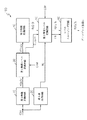
図1は本発明の第1実施例による対比及び明度改善装置100のブロック図を示す。
図1を参照すれば、対比及び明度改善装置100は第1画像変換回路10、最大値出力回路20、第1輝度レベル変換回路30、第2画像変換回路40、第2輝度レベル変換回路50及びレベルスムージング回路60を備える。
第1画像変換回路10は入力されるRGBビデオ信号(図1のRGB)を受信し、それらをYCbCrカラー空間情報に変換し、デジタル輝度情報Y及び色相情報を第1輝度レベル変換回路30に出力する。
【0014】
色相情報は2色差要素Cb,Crを保有し、Crは青色信号と基準信号との差を示し、Cbは赤色信号と基準信号との差を示す。従って、第1画像変換回路10は8ビットRGBビデオ信号を8ビットYCbCrデータに変換する。
最大値出力回路20は入力されるRGBビデオ信号RGBを受信し、それぞれのレベルを比較し、RGBビデオ信号RGBのうち最大レベルを有する信号M1を第2輝度レベル変換回路50に出力する。
本実施の形態の最大値出力回路20は第1比較器及び第2比較器を備えており、前記第1比較器はBビデオ信号とGビデオ信号とを受信し、各信号のレベルを比較し、その比較結果を出力する。
【0015】
前記第2比較器は前記第1比較器の出力信号とRビデオ信号とを受信して各信号のレベルを比較し、その比較結果を出力する。
従って、前記第2比較器の出力信号M1はRビデオ信号、Gビデオ信号及びBビデオ信号のうち最大レベルを有するビデオ信号である。
第1輝度レベル変換回路30は第1画像変換回路10の出力信号YCbCrを受信し、第1制御信号CHMに応じて図2及び図3に示された中間関数及び後述する数式(1)を利用して輝度情報(または輝度信号)Yだけのレベルを下げ、その結果Y’CbCrを第2画像変換回路40に出力する。すなわち、第1輝度レベル変換回路50は輝度信号Yのレベルだけを所定の利得C_gainほど下げる。
【0016】
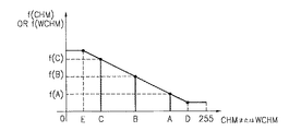
図2は本発明による第1輝度レベル変換回路にて使われる中間関数の例を示す。
図2に示された中間関数の傾き(直線E−D)はユーザまたは対比及び明度改善装置100のメーカにより可変である。入力される値CHM,(後述する)WCHMの範囲は0ないし255と設定できる。
【0017】
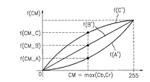
図3は本発明による第1輝度レベル変換回路にて使われる輝度レベル変換関数(数式(1)のf(CM))の例を示す。
図3に示された各関数f(A’),f(B’),f(C’)は図2のf(A),f(B),f(C)にそれぞれ対応する。入力されるCMの範囲は0ないし255と設定できる。
図2及び図3を参照すれば、第1制御信号CHMがA値を有する場合、輝度レベル変換関数はf(A’)であり、第1制御信号CHMがB値を有する場合、輝度レベル変換関数はf(B’)であり、第1制御信号CHMがC値を有する場合、輝度レベル変換関数はf(C’)である。
【0018】
すなわち、各制御信号CHMの値A,BまたはCに対応する各関数f(A’),f(B’),f(C’)は対比及び明度改善装置100のメーカまたはユーザにより与えられうる。
従って、第1輝度レベル変換回路30は図2及び図3に示された関数を利用して入力された輝度信号Yのレベルを数式(1)を通じて下げ、その結果Y’CbCrを出力する。また、第1輝度レベル変換回路30は数式(1)を通じて計算されたそれらC_gainを第2輝度レベル変換回路50に出力する。
【0019】
数式(1)を以下に示す。
C_gain=f(CM)/CM
Y’=Y/C_gain ・・・・・(1)
ここで、CMは第1画像変換回路10から出力される2色差要素(または2色差信号)Cb及びCrのうち最大値を示し、f(CM)はCMの出力値を意味する。
【0020】
そして、Yは第1輝度レベル変換回路30の入力信号を示し、Y’がYを第1輝度レベル変換回路30で変換した出力信号である。
第1輝度レベル変換回路30は輝度レベル変換過程にて輝度信号Yが色帯域を外れることを防止するために、輝度信号Yのレベルを下げる。そして、下げられた輝度信号Yのレベルは第2輝度レベル変換回路50により補償される。
【0021】
図2及び図3を参照すれば、入力される第1制御信号CHMの値が増加するにしたがって、利得C_gainは減少する。例えば、入力される第1制御信号CHMの値がAであり、2色差信号Cb及びCrの最大値がCMの場合、第1輝度レベル変換回路30は関数f(A’)を利用して利得C_gain=f(CM_A/CM)を計算し、前記利得C_gain=f(CM_A/CM)を利用して輝度信号Yのレベルを下げる。
【0022】
第2画像変換回路40は第1輝度レベル変換回路30の出力信号Y’CbCrを受信し、それらをRGBビデオ信号に変換し、その結果R1G1B1を第2輝度レベル変換回路50に出力する。
第2輝度レベル変換回路50は最大値出力回路20の出力信号M1、第1輝度レベル変換回路30から出力される利得C_gain、第2画像変換回路40から出力されるビデオ信号R1G1B1及び第2制御信号LUMを受信し、第2画像変換回路40から出力されるビデオ信号R1G1B1それぞれの利得を数式(2)及び数式(3)を通じて増やし、その結果R2B2G2をレベルスムージング回路60に出力する。
【0023】
また、第2輝度レベル変換回路50はレベルスムージング回路60をイネーブルさせるためのイネーブル信号ENを生成してレベルスムージング回路60に出力する。
数式(2)を以下に示す。
Gain=fM1/M1
Y_gain=Min((Gain×C_Gain),255/(Max(R1,G1,B1)) ・・・・・(2)
【0024】
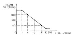
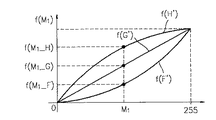
図4は本発明による第2輝度レベル変換回路にて使われる中間関数の例を示す。図4に示された中間関数の傾き、E値またはI値はユーザまたは対比及び明度改善装置100のメーカにより可変である。
【0025】
図5は本発明による第2輝度レベル変換回路にて使われる輝度レベル変換関数の例を示す。図5に示された各関数f(F’),f(G’),f(H’)は図4のf(F),f(G),f(H)にそれぞれ対応する。図4のf(F),f(G),f(H)にそれぞれ対応する各関数f(F’),f(G’),f(H’)はユーザまたは対比及び明度改善装置100のメーカにより予め設定されている。図4及び図5を参照すれば、第2制御信号LUMの値が大きくなる場合、数式(2)による利得Gainは減る。
【0026】
第2輝度レベル変換回路50は色相保存を補償するためにGain×C_Gainと255/(Max(R1,G1,B1))のうち最小利得値Y_gainを計算し、数式(3)を通じてRビデオ信号、Gビデオ信号及びBビデオ信号の利得をそれぞれ増加して、その結果R2G2B2を出力する。
数式(3)を以下に示す。
R2=Y_gain×R1
G2=Y_gain×G1
B2=Y_gain×B1 ・・・・(3)
【0027】
レベルスムージング回路60はイネーブル信号ENに応じて画素単位で第2輝度レベル変換回路50の出力信号R2G2B2をフィルタリングし、その結果R3G3B3をCDT、TFT−LCDとPDPなどを含むディスプレイ装置に出力する。
レベルスムージング回路60は「前の画素値」と「現在の画素値」とについて加重平均を使用してフィルタリングをする。従って、レベルスムージング回路60はイネーブル信号ENが活性化される場合、すなわち第2輝度レベル変換回路50の出力信号のレベルが拡張される場合、レベルが拡張された区間について選択的にスムージングする。
【0028】
すなわち、レベルスムージング回路60は輝度信号のレベルを変換する過程にて輝度信号のレベルが高まった区間にて雑音が増幅されることを抑制するために、輝度信号のレベルが高まった領域についてだけ選択的に低域通過フィルタリングを行う。従って、レベルスムージング回路60は第2輝度レベル変換回路50の出力信号R2G2B2の急激な変化を防止する。
また、対比及び明度改善装置100は第1画像変換回路10、第1輝度レベル変換回路30、第2画像変換回路40、第2輝度レベル変換回路50及びレベルスムージング回路60を備えうる。この場合の各回路10,30,40,50及び60の動作と機能とは前述の各回路10,30,40,50及び60の動作と機能と実質的に同一である。
【0029】
図6は本発明の第2実施例による対比及び明度改善装置200のブロック図を示す。図6を参照すれば、対比及び明度改善装置200は第1画像変換回路10、最大値出力回路20、画像統計推定回路250、第1輝度レベル変換回路30、色相制御回路210、第2画像変換回路220、第2輝度レベル変換回路230及びレベルスムージング回路240を備える。
第1画像変換回路10はRGBビデオ信号RGBを受信し、それらをYCbCrカラー空間情報に変換し、デジタル輝度情報(または輝度信号)Y及び色相情報(または色相信号)を画像統計推定回路250及び第1輝度レベル変換回路30に出力する。
【0030】
色相情報または色相信号は2色差要素(または2色差信号)Cb,Crを保存する。Crは青色信号と基準信号との差を示し、Cbは赤色信号と基準信号との差を示す。最大値出力回路20は図1の最大値出力回路20とその構造及び機能が同一なので詳細な説明は省略する。
画像統計推定回路250は輝度統計計算回路251及び色相統計計算回路253を備える。
輝度統計計算回路251は第1画像変換回路10の出力信号YCbCrのうち輝度情報Yだけを受信し、現在フレームに関する輝度情報Yの平均値を計算し、その結果LUMを第2輝度レベル変換回路230に出力する。例えば、輝度情報Yが8ビットで示される場合、輝度統計計算回路251は256レベルのうち1レベルLUMを出力する。
【0031】
色相統計計算回路253は第1画像変換回路10の出力信号YCbCrのうち色相情報Cb,Crを受信し、現在フレームに関する色相情報の平均値を計算し、その結果CHMを第1輝度レベル変換回路30に出力する。例えば、色相情報が8ビットで示される場合、色相統計計算回路253は256レベルのうち1レベルCHMを出力する。
色相統計計算回路253は2色差信号Cb,Crの最大値の平均値Mean(Max(Cb,Cr))を計算するか、あるいは2色差信号Cb,Crの最大値の最大値Max(Max(Cb,Cr))を計算してその結果を出力する。
【0032】
第1輝度レベル変換回路30は第1画像変換回路10の出力信号YCbCrを受信し、色相統計計算回路253の出力信号CHMに応じて図2及び図3に示された関数と数式(1)とを利用して輝度情報Yだけのレベルを下げ、その結果Y’CbCrを色相制御回路210に出力する。また、第1輝度レベル変換回路30は数式(1)を通じて計算されたそれらC_gainを第2輝度レベル変換回路230に出力する。
第1輝度レベル変換回路30が輝度情報Yのレベルを下げるための技術的思想は図1に示された第1輝度レベル変換回路30が輝度情報Yのレベルを下げるための技術的思想と同一である。従って、第1輝度レベル変換回路30は図2及び図3に示された関数を利用して輝度情報Yのレベルを下げられる。
【0033】
第1輝度レベル変換回路30は輝度信号のレベル変換過程にて輝度信号Yが色帯域から外れることを防止するため、輝度信号Yのレベルを下げる。そして、下げられた輝度信号Yのレベルは第2輝度レベル変換回路230により補償される。
色相制御回路210は第1輝度レベル変換回路30の出力信号Y’CbCrを受信し、制御信号θに応じて数式(4)を通じて2色差要素Cb及びCrを回転変換し、その結果Y”Cb’Cr’を第2画像変換回路220に出力する。制御信号θは対比及び明度改善装置100の外部から入力される。
例えば、制御信号θはユーザ入力装置などを通じて入力されうる。制御信号θは元来の2色差要素Cb及びCrを示す座標を基準に所定角度回転させるための変数である。従って、制御信号θは所定の角度、cosθ及びsinθと与えられうる。色相制御回路210は制御信号θに対応するルックアップテーブルを備えられる。
【0034】
数式(4)を以下に示す。
Y”=0.5×Y’
Cb’=0.5×(cosθ×Cb+sinθ×Cr)
Cr’=0.5×(−sinθ×Cb+cosθ×Cr) ・・・・(4)
色相制御回路210は回転変換過程にて輝度信号Y’及び2色差信号Cb及びCrが色帯域を外れることを防止するために、輝度信号Y’及び2色差信号Cb及びCrのレベルを数式(4)を通じて下げる。数式(4)に使われた縮尺(0.5)は可変である。
【0035】
第2画像変換回路220は色相制御回路210の出力信号Y”Cb’Crを受信し、それらをRGBビデオ信号に変換し、その結果R1G1B1を第2輝度レベル変換回路230に出力する。
第2輝度レベル変換回路230は最大値出力回路20の出力信号M1、第1輝度レベル変換回路30から出力される利得C_gain、第2画像変換回路220から出力されるビデオ信号R1G1B1及び輝度統計計算回路251から出力される信号LUMを受信し、第2画像変換回路220から出力される各ビデオ信号R1G1B1の利得を数式(5)及び数式(3)を通じて増やし、その結果R2B2G2をレベルスムージング回路240に出力する。
【0036】
また、第2輝度レベル変換回路230はレベルスムージング回路240をイネーブルさせるためのイネーブル信号ENを生成してレベルスムージング回路240に出力する。
数式(5)を以下に示す。
Gain=FM1/M1
Y_gain=Min((Gain×C_Gain×2),255/(Max(R1,G1,B1)) ・・・・(5)
【0037】
第2輝度レベル変換回路230が利得Gainを計算するための技術的思想は図1に示された第2輝度レベル変換回路50が利得Gainを計算するための技術的思想と実質的に同一である。
従って、第2輝度レベル変換回路230は図4に示された中間関数及び図5に示された各輝度レベル変換関数f(F’),f(G’),f(H’)を通じて最大値出力回路30の出力信号M1に関する利得Gainを計算できる。
【0038】
第2輝度レベル変換回路230は、色相保存を補償するためにGain×C_Gain×2と255/Max(R1,G1,B1)のうちの最小の利得値Y_gainを出力する。そして、第2輝度レベル変換回路230は第1輝度レベル変換回路30及び色相制御回路210により減った利得を補償するための縮尺、すなわち利得C_gainと2とを利得Gainに掛け合わせる。
レベルスムージング回路240の構造及び機能は図1のレベルスムージング回路60の構造及び機能と同一なので詳細な説明は省略する。
【0039】
図6に示された対比及び明度改善装置200はフレーム単位で入力されるビデオ信号(または画像)のヒストグラム、平均値、最小値、最大値などを含む統計的特性を利用して輝度信号Y及び色差信号Cb及びCrを適応的に制御できる。
本発明による対比及び明度改善装置200はディスプレイ装置の全体スクリーンまたは全体スクリーンのうち一部領域にディスプレイされる停止画像の対比及び明度を適切に制御できる。
よって、本発明による対比及び明度改善装置200は入力される画素のコントラストを図3及び図5に示された非線型関数を利用して調節でき、同時にコントラスト調節過程にて生じうる色相鮮明度の変化を抑制できる。
【0040】
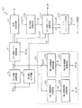
図7は本発明の第3実施例による対比及び明度改善装置300のブロック図を示す。図7を参照すれば、対比及び明度改善装置300は第1画像変換回路10、最大値出力回路20、画像統計推定回路250、第1輝度レベル変換回路31、色相制御回路210、第2画像変換回路220、第2輝度レベル変換回路231及びレベルスムージング回路240を備える。
【0041】
第1画像変換回路10はRGBビデオ信号RGBを受信し、それらをYCbCrカラー空間情報に変換し、デジタル輝度情報(または輝度信号)Y及び色相情報(または色相信号)を画像統計推定回路250及び第1輝度レベル変換回路30に出力する。最大値出力回路20は図1の最大値出力回路20とその構造及び機能が同一なので詳細な説明は省略する。
画像統計推定回路250は第1輝度統計計算回路254、第2輝度統計計算回路256、第1色相統計計算回路255及び第2色相統計計算回路257を備える。
【0042】
第1輝度統計計算回路254は第1画像変換回路10の出力信号YCbCrのうち輝度情報Yだけを受信し、現在フレームに関する輝度情報Yの統計的特性(例えば平均値)を計算し、その結果LUMを第2輝度統計計算回路256に出力する。
第2輝度統計計算回路256は前のフレームに関する輝度情報Yの統計的特性(例えば、平均値)と現在フレームに関する輝度情報Yの統計的特性(例えば、平均値)に対する加重平均を計算し、その結果WLUMを第2輝度レベル変換回路231に出力する。
加重平均を利用する理由は現在フレームの輝度情報Yの統計的特性(平均値)が急激に変化することを防止するためである。従って、第2輝度統計計算回路256は累積的にあらゆるフレームに関する輝度情報Yの統計的特性(平均値)を計算できる。
【0043】
第2輝度統計計算回路256にて使われる加重平均は数式(6)により計算できる。
数式(6)を以下に示す。
加重平均=(1−w)×M_cf+w×M_pf ・・・・(6)
ここで、wは加重値を示し、wの範囲は0と同じかそれより大きくて1より小さい。M_cfは現在フレームの輝度情報Yの平均値を示し、M_pfは前のフレームの輝度情報Yの平均値を示す。
第1輝度統計計算回路254及び第2輝度統計計算回路256は輝度情報Yに関する平均値、最小値、最大値またはヒストグラムなどを含むあらゆる統計的特性も計算できる。
【0044】
第1色相統計回路255は第1画像変換回路10の出力信号YCbCrのうち色相情報Cb,Crを受信し、現在フレームに関する色相情報の統計的特性(平均値)を計算し、その結果CHMを第2色相統計計算回路257に出力する。
第1色相統計計算回路255は2色差信号Cb,Crの最大値の平均値Mean(Max(Cb,Cr))を計算するか、あるいは2色差信号Cb,Crの最大値の最大値Max(Max(Cb,Cr))を計算してその結果を出力できる。
【0045】
第2色相統計計算回路257は前のフレームに関する色相情報の統計的特性(平均値)と現在フレームに関する色相情報の平均値に対する加重平均とを計算し、その結果WCHMを第1輝度レベル変換回路31に出力する。第2色相統計計算回路257は累積的にあらゆるフレームに関する色相情報の平均値WCHMを計算できる。
第2色相統計計算回路257による加重平均は数式(6)を通じて計算できる。ここで、「M_cf」は現在フレームの色相情報の平均値を示し、「M_pf」は前のフレームの色相情報の平均値を示す。
例えば、第1色相統計計算回路255及び第2色相統計計算回路257それぞれが2色差信号Cb,Crの最大値に対する平均値を計算してその結果を出力するならば、第2色相統計計算回路257は累積的にあらゆるフレームに関する2色差要素の最大値の平均値を計算してその結果を出力する。
【0046】
第1輝度レベル変換回路31の機能は図6の第1輝度レベル変換回路30の機能と実質的に同一である。従って、第1輝度レベル変換回路31は第1画像変換回路10の出力信号YCbCrを受信し、第2色相統計計算回路257の出力信号WCHMに応じて図2及び図3に示された中間関数及び数式(1)を利用して輝度情報Yだけのレベルを下げ、その結果Y’CbCrを色相制御回路210に出力する。
色相制御回路210の機能と動作とは図6の色相制御回路210の機能と動作と同一である。すなわち、色相制御回路210は第1輝度レベル変換回路31の出力信号Y’CbCrを受信し、制御信号θに応じて数式(4)を通じて2色差要素Cb及びCrを回転変換し、その結果Y”Cb’Cr’を第2画像変換回路220に出力する。
【0047】
第2画像変換回路220は色相制御回路210の出力信号Y”Cb’Cr’を受信し、それらをRGBビデオ信号に変換し、その結果R1G1B1を第2輝度レベル変換回路231に出力する。すなわち、第2画像変換回路220はYCbCrデータをRGBデータに変換する。
第2輝度レベル変換回路231の機能と動作とは図6の第2輝度レベル変換回路230の機能と動作と実質的に同一である。
すなわち、第2輝度レベル変換回路231は最大値出力回路20の出力信号M1、第1輝度レベル変換回路31から出力される利得C_gain、第2画像変換回路220から出力されるビデオ信号R1G1B1及び第2輝度統計計算回路256から出力される信号WLUMを受信し、第2画像変換回路220から出力されるビデオ信号R1G1B1の利得を数式(5)及び数式(3)を通じて増やし、その結果R2B2G2をレベルスムージング回路240に出力する。
【0048】
レベルスムージング回路240はイネーブル信号ENに応じて画素単位で第2輝度レベル変換回路231の出力信号R2G2B2をフィルタリングし、その結果R3G3B3をTFT−LCDとPDPなど含むディスプレイ装置に出力する。レベルスムージング回路240は図6のレベルスムージング回路240と同一である。
図7に示された対比及び明度改善装置はフレーム単位で入力されるビデオ画像のヒストグラム、平均値、最小値、最大値などを含む統計的特性を利用して輝度信号及び/または色差信号Cb及びCrを適切に制御できる。
【0049】
本発明による対比及び明度改善装置300はディスプレイ装置の全体スクリーンにて、または全体スクリーンのうち一部領域にてディスプレイされる動画像の対比及び明度を適切に制御できる。
本発明の実施例による色相保存のための適応的対比及び明度改善法は図1及び図4を通じて分かることは当然である。本発明の実施例による対比及び明度改善装置は1つの半導体チップまたはシステムオンチップで具現できる。
本発明はコンピュータにより読み込み可能な記録媒体にコンピュータで読み込み可能なコードとして具現できる。ここで、コンピュータにより読み込み可能な記録媒体はコンピュータシステムにより読み込まれうるデータを保存する能力を有したあらゆる記録装置、例えばROM、RAM、CD−ROM、磁気テープ、フロッピー(登録商標)ディスク、光データ記憶装置などを含む。
【0050】
その上、コンピュータにより読み込み可能な記録媒体はインターネットを通じてデータを伝送する搬送波である場合もある。コンピュータにより読み込み可能な記録媒体はネットワークに連結されたコンピュータシステムに必須的に設置されたり、コンピュータにより読み込み可能なコードとして記憶されうる。本発明の技術的な思想はハードウエア及びソフトウエアの結合により具現されうる。
本発明は図面に示された一実施例を参考に説明されたが、それは例示的なものに過ぎず、本技術分野の当業者ならばそれから多様な変形及び均等な他実施例が可能であるという点が理解されるであろう。従って、本発明の真の技術的保護範囲は特許請求の範囲の技術的思想により決まるべきである。
【0051】
【発明の効果】
このように、本発明のビデオ画像の色相保存のための適応的対比/明度改善法及び対比/明度改善装置によれば、入力されるビデオ画像のレベルにより選択的にコントラストを拡張すると同時に、コントラストを拡張する過程にて生じうる色相変化を抑制することができる。
【図面の簡単な説明】
【図1】本発明の第1実施例による対比及び明度改善装置のブロック図。
【図2】本発明による第1輝度レベル変換回路にて使われる中間関数の一例を示す図。
【図3】本発明による第1輝度レベル変換回路にて使われる輝度レベル変換関数の一例を示す図。
【図4】本発明による第2輝度レベル変換回路にて使われる中間関数の一例を示す図。
【図5】本発明による第2輝度レベル変換回路にて使われる輝度レベル変換関数の一例を示す図。
【図6】本発明の第2実施例による対比及び明度改善装置のブロック図。
【図7】本発明の第3実施例による対比及び明度改善装置のブロック図。
【符号の説明】
10 第1画像変換回路
20 最大値出力回路
30 第1輝度レベル変換回路
40 第2画像変換回路
50 第2輝度レベル変換回路
60 レベルスムージング回路
100 明度改善装置[0001]
TECHNICAL FIELD OF THE INVENTION
The present invention relates to video image signal processing, and more particularly, to a contrast / brightness improving method and a contrast / brightness improving apparatus for storing a hue of a video image displayed on a display device.
[0002]
[Prior art]
In an environment where the dynamic range of the video image output to the display device is limited, the level of the input video image is controlled or converted by a nonlinear function in order to improve the contrast of the video image output to the display device. Is done.
At this time, the nonlinear function is already fixed, but can be variably provided based on a histogram of an input video image or the like.
When the level of the video image input by the nonlinear function is simply converted, the contrast of a specific level region of the video image can be limitedly improved, but a white component is added to a portion where the level increases. This causes a problem that the saturation of the image is reduced.
[0003]
Meanwhile, there has been proposed a method of adjusting a gain based on a luminance direction component of an RGB vector of an input video image in order to improve contrast while preserving hue.
According to this method, the extension gain is relatively increased for a signal whose luminance direction component is close to the cursor achromatic color, and the extension gain is relatively decreased for a signal of high chroma having a large color difference component.
Such a method can maintain hue clarity while increasing overall brightness. However, in the above method, since the gain is adjusted only by the hue of the image, it is not possible to selectively expand the gain according to the level of the video image, and the dynamic range is extended, so that a hue saturation phenomenon may occur. is there.
[0004]
[Problems to be solved by the invention]
SUMMARY OF THE INVENTION It is an object of the present invention to provide a method and apparatus capable of selectively expanding contrast and preserving hue according to the level of an input video signal.
[0005]
[Means for Solving the Problems]
In order to achieve the above technical object, an apparatus for improving contrast and brightness of a video signal displayed on a display device according to the present invention receives a luminance signal and a hue signal, and receives the luminance signal and the hue signal according to a first control signal. A first luminance level conversion circuit for lowering the level of the luminance signal and outputting the hue signal and the luminance signal having the reduced level; and receiving an output signal of the first luminance level conversion circuit to convert the received signal into an RGB video signal. An image conversion circuit for converting the RGB video signal, receiving the RGB video signal, simultaneously increasing a level of each of the RGB video signals according to a second control signal, and outputting an RGB video signal having the enhanced level. 2 includes a luminance level conversion circuit.
The display device is preferably a color display tube (CDT), a thin film transistor liquid crystal display (TFT-LCD), or a plasma display panel (PDP).
[0006]
An apparatus for improving the contrast and brightness of a video signal displayed on a display device according to the present invention includes a first image conversion circuit for converting an RGB video signal into a luminance signal and a hue signal, and converting the RGB video signal. Receiving and comparing the signal levels of the RGB video signals, and outputting a maximum value output circuit for outputting an R video signal, a G video signal, or a B video signal having a maximum level; and outputting the luminance signal and the hue signal. A first luminance level conversion circuit for receiving and lowering the level of the luminance signal in accordance with a first control signal, and outputting the hue signal and a luminance signal having the reduced level; and a first luminance level conversion circuit A second image conversion circuit for receiving the output signal of the RGB video signal and converting the RGB video signal into an RGB video signal; Enhance the level of each of the RGB video signal in response to the output signal and the second control signal of the circuit at the same time, and a second brightness level converting circuit for outputting a RGB video signal with enhanced levels.
[0007]
An apparatus for improving contrast and brightness of a video signal displayed on a display device according to the present invention receives a luminance signal and a hue signal, and uses a statistical characteristic of the hue signal to level the luminance signal. A first luminance level conversion circuit for lowering the output and outputting the result, receiving an output signal of the first luminance level conversion circuit, rotating and converting the hue signal according to a control signal, and outputting the result. Hue control circuit, an image conversion circuit for receiving an output signal of the hue control circuit and converting it into an RGB video signal, and a level of each of the RGB video signals using a statistical characteristic of the luminance signal. And a second luminance level conversion circuit for outputting the result.
The display device is a CDT, a TFT-LCD and a PDP. The statistical characteristic of the hue signal is an average value of the hue signal for a current frame, and the statistical characteristic of the luminance signal is an average value of the luminance signal for a current frame.
[0008]
An apparatus for improving the contrast and brightness of a video signal displayed on a display device according to the present invention includes a first image conversion circuit for converting an RGB video signal into a luminance signal and a hue signal, and converting the RGB video signal. Receiving, comparing each of the RGB video signals, receiving a maximum value output circuit for outputting an R video signal, a G video signal, or a B video signal having a maximum level, and receiving the luminance signal and the hue signal; A first luminance level conversion circuit for lowering the level of the luminance signal using a statistical characteristic of the hue signal and outputting a result thereof; and receiving an output signal of the first luminance level conversion circuit to control the luminance signal. A hue control circuit for rotating and converting the hue signal in accordance with the signal and outputting the result, A second image conversion circuit for converting into a video signal, and increasing the level of each of the RGB video signals using statistical characteristics of the output signal of the maximum value output circuit and the luminance signal, and outputting the result. And a second luminance level conversion circuit.
[0009]
A method for improving contrast and brightness of a video signal displayed on a display device according to the present invention includes receiving a first video signal including a luminance signal and a hue signal, and receiving the first video signal according to a first control signal. Lowering the level and outputting a second video signal including the hue signal and the luminance signal having the lowered level; receiving the second video signal and converting the second video signal into an RGB video signal; And simultaneously increasing the level of each of the RGB video signals according to a second control signal, and outputting an RGB video signal having the increased level.
[0010]
The first control signal is a signal generated from statistical characteristics of the hue signal for a current frame, and the second control signal is a signal generated from statistical characteristics of the luminance signal for a current frame. The statistical property is an average value, a minimum value, a maximum value, or a histogram.
The first control signal may be a signal generated from a weighted average of an average value of the hue signal for a previous frame and an average value of the hue signal for a current frame, or the second control signal may be a signal of a previous frame. A weighted average of the average value of the luminance signal for the current frame and the average value of the luminance signal for the current frame.
[0011]
A method for improving contrast and brightness of a video signal displayed on a display device according to the present invention includes the steps of (a) converting an RGB video signal into a luminance signal and a hue signal, and (b) converting the RGB video signal. Receiving and comparing each of the RGB video signals and outputting an R, G, or B video signal having a maximum level; and (c) receiving the luminance signal and the hue signal, Lowering the level of the luminance signal according to a control signal and outputting the hue signal and the luminance signal having the reduced level; and (d) luminance having the hue signal and the reduced level of the step (c). Receiving the signal and converting it to an RGB video signal; and (e) receiving the RGB video signal of the step (d), outputting the output signal of the step (b) and the second control. At the same time it is increasing the level of each received RGB video signal in response to items, comprising the step of outputting the RGB video signal with enhanced levels.
[0012]
BEST MODE FOR CARRYING OUT THE INVENTION
For a full understanding of the present invention, the operational advantages thereof, and the objects achieved by the practice of the invention, reference should be made to the accompanying drawings, which illustrate preferred embodiments of the present invention, and to the details contained therein. No.
Hereinafter, the present invention will be described in detail by explaining preferred embodiments of the invention with reference to the accompanying drawings. The same reference numerals provided in each drawing indicate the same members.
[0013]
FIG. 1 is a block diagram of a contrast and
Referring to FIG. 1, the contrast and
The first
[0014]
The hue information has two color difference elements Cb and Cr, where Cr indicates the difference between the blue signal and the reference signal, and Cb indicates the difference between the red signal and the reference signal. Therefore, the first
The maximum
The maximum
[0015]
The second comparator receives the output signal of the first comparator and the R video signal, compares the level of each signal, and outputs the comparison result.
Therefore, the output signal M of the second comparator1Is a video signal having the maximum level among the R video signal, the G video signal, and the B video signal.
The first luminance
[0016]
FIG. 2 shows an example of an intermediate function used in the first luminance level conversion circuit according to the present invention.
The slope (line ED) of the intermediate function shown in FIG. 2 is variable depending on the user or the manufacturer of the contrast and
[0017]
FIG. 3 shows an example of a brightness level conversion function (f (CM) in Equation (1)) used in the first brightness level conversion circuit according to the present invention.
Each function f (A '), f (B'), f (C ') shown in FIG. 3 corresponds to f (A), f (B), f (C) in FIG. 2, respectively. The range of the input CM can be set from 0 to 255.
Referring to FIGS. 2 and 3, when the first control signal CHM has the A value, the luminance level conversion function is f (A ′), and when the first control signal CHM has the B value, the luminance level conversion function is f (A ′). The function is f (B ′), and when the first control signal CHM has the C value, the luminance level conversion function is f (C ′).
[0018]
That is, each function f (A ′), f (B ′), f (C ′) corresponding to the value A, B or C of each control signal CHM can be given by the manufacturer or user of the comparison and
Accordingly, the first luminance
[0019]
Equation (1) is shown below.
C_gain = f (CM) / CM
Y '= Y / C_gain (1)
Here, CM indicates the maximum value of the two color difference elements (or two color difference signals) Cb and Cr output from the first
[0020]
Y indicates an input signal of the first brightness
The first luminance
[0021]
Referring to FIGS. 2 and 3, as the value of the input first control signal CHM increases, the gain C_gain decreases. For example, when the value of the input first control signal CHM is A and the maximum value of the two-color difference signals Cb and Cr is CM, the first luminance
[0022]
The second
The second luminance
[0023]
Further, the second luminance
Equation (2) is shown below.
Gain = fM1/ M1
Y_gain = Min ((Gain × C_Gain), 255 / (Max (R1, G1, B1)) ・ ・ ・ ・ ・ ・ ・ (2)
[0024]
FIG. 4 shows an example of an intermediate function used in the second luminance level conversion circuit according to the present invention. The slope, E value, or I value of the intermediate function shown in FIG. 4 is variable by the user or the manufacturer of the contrast and
[0025]
FIG. 5 shows an example of a brightness level conversion function used in the second brightness level conversion circuit according to the present invention. The functions f (F '), f (G'), f (H ') shown in FIG. 5 correspond to f (F), f (G), f (H) in FIG. 4, respectively. The functions f (F ′), f (G ′) and f (H ′) corresponding to f (F), f (G) and f (H) in FIG. It is set in advance by the manufacturer. Referring to FIGS. 4 and 5, when the value of the second control signal LUM increases, the gain Gain according to Equation (2) decreases.
[0026]
The second luminance
Equation (3) is shown below.
R2= Y_gain × R1
G2= Y_gain × G1
B2= Y_gain × B1・ ・ ・ ・ (3)
[0027]
The
The
[0028]
That is, the
Further, the contrast and
[0029]
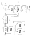
FIG. 6 is a block diagram of a contrast and
The first
[0030]
The hue information or hue signal stores two color difference elements (or two color difference signals) Cb and Cr. Cr indicates the difference between the blue signal and the reference signal, and Cb indicates the difference between the red signal and the reference signal. The maximum
The image
The luminance
[0031]
The hue
The hue
[0032]
The first luminance
The technical idea for the first luminance
[0033]
The first luminance
The
For example, the control signal θ may be input through a user input device or the like. The control signal θ is a variable for rotating the original two-color difference elements Cb and Cr by a predetermined angle based on the coordinates indicating the two elements. Therefore, the control signal θ can be given as a predetermined angle, cos θ and sin θ. The
[0034]
Equation (4) is shown below.
Y ″ = 0.5 × Y ′
Cb ′ = 0.5 × (cos θ × Cb + sin θ × Cr)
Cr ′ = 0.5 × (−sin θ × Cb + cos θ × Cr) (4)
The
[0035]
The second
The second luminance
[0036]
Also, the second luminance
Equation (5) is shown below.
Gain = FM1/ M1
Y_gain = Min ((Gain × C_Gain × 2), 255 / (Max (R1, G1, B1)) ・ ・ ・ ・ (5)
[0037]
The technical idea for the second luminance
Accordingly, the second brightness
[0038]
The second luminance
The structure and function of the
[0039]
The
The contrast and
Accordingly, the
[0040]
FIG. 7 is a block diagram of a contrast and
[0041]
The first
The image
[0042]
The first luminance
The second luminance
The reason for using the weighted average is to prevent a sudden change in the statistical characteristics (average value) of the luminance information Y of the current frame. Therefore, the second luminance
[0043]
The weighted average used in the second luminance
Equation (6) is shown below.
Weighted average = (1−w) × M_cf + w × M_pf (6)
Here, w indicates a weight value, and the range of w is equal to or larger than 0 and smaller than 1. M_cf indicates the average value of the luminance information Y of the current frame, and M_pf indicates the average value of the luminance information Y of the previous frame.
The first luminance
[0044]
The first hue
The first hue
[0045]
The second hue
The weighted average by the second hue
For example, if each of the first hue
[0046]
The function of the first luminance
The functions and operations of the
[0047]
The second
The function and operation of the second luminance
That is, the second luminance
[0048]
The
The apparatus for improving contrast and brightness shown in FIG. 7 uses a luminance characteristic and / or a color difference signal Cb and a luminance signal and / or a chrominance signal Cb using statistical characteristics including a histogram, an average value, a minimum value, and a maximum value of a video image input in units of frames. Cr can be controlled appropriately.
[0049]
The
It is obvious that the adaptive contrast and brightness improvement method for preserving hue according to the embodiment of the present invention can be understood from FIGS. The apparatus for improving contrast and brightness according to an embodiment of the present invention can be implemented with one semiconductor chip or a system-on-chip.
The present invention can be embodied as computer readable codes on a computer readable recording medium. Here, the computer-readable recording medium is any recording device capable of storing data that can be read by a computer system, such as a ROM, a RAM, a CD-ROM, a magnetic tape, a floppy disk, and optical data. Including storage devices.
[0050]
In addition, the computer readable recording medium may be a carrier that transmits data over the Internet. The computer-readable recording medium may be essentially installed in a computer system connected to a network, or may be stored as computer-readable code. The technical concept of the present invention can be realized by combining hardware and software.
While the present invention has been described with reference to an embodiment shown in the drawings, it is by way of example only and various modifications and equivalents are possible from those skilled in the art. It will be understood that. Therefore, the true scope of the present invention should be determined by the appended claims.
[0051]
【The invention's effect】
As described above, according to the adaptive contrast / brightness improving method and contrast / brightness improving apparatus for preserving the hue of a video image according to the present invention, the contrast can be selectively expanded according to the level of the input video image, and at the same time, the contrast can be enhanced. Hue change that may occur in the process of expanding the image can be suppressed.
[Brief description of the drawings]
FIG. 1 is a block diagram of an apparatus for improving contrast and brightness according to a first embodiment of the present invention.
FIG. 2 is a diagram showing an example of an intermediate function used in a first luminance level conversion circuit according to the present invention.
FIG. 3 is a diagram showing an example of a brightness level conversion function used in a first brightness level conversion circuit according to the present invention.
FIG. 4 is a diagram showing an example of an intermediate function used in the second luminance level conversion circuit according to the present invention.
FIG. 5 is a diagram showing an example of a brightness level conversion function used in a second brightness level conversion circuit according to the present invention.
FIG. 6 is a block diagram of an apparatus for improving contrast and brightness according to a second embodiment of the present invention.
FIG. 7 is a block diagram of an apparatus for improving contrast and brightness according to a third embodiment of the present invention.
[Explanation of symbols]
10 First image conversion circuit
20 ° maximum value output circuit
30 ° first luminance level conversion circuit
40 ° second image conversion circuit
50 ° second luminance level conversion circuit
60 ° level smoothing circuit
100 ° brightness improvement device
Claims (35)
輝度信号及び色相信号を受信し、第1制御信号に応じて前記輝度信号のレベルを下げ、前記色相信号及び下げられたレベルを有する輝度信号を出力するための第1輝度レベル変換回路と、
前記第1輝度レベル変換回路の出力信号を受信してRGBビデオ信号に変換するための画像変換回路と、
前記RGBビデオ信号を受信し、第2制御信号に応じて前記RGBビデオ信号それぞれのレベルを同時に高め、高められたレベルを有するRGBビデオ信号を出力するための第2輝度レベル変換回路とを備えることを特徴とするビデオ信号の対比及び明度改善装置。An apparatus for improving contrast and brightness of a video signal displayed on a display device,
A first luminance level conversion circuit for receiving a luminance signal and a hue signal, reducing the level of the luminance signal according to a first control signal, and outputting the hue signal and a luminance signal having the reduced level;
An image conversion circuit for receiving an output signal of the first luminance level conversion circuit and converting the output signal into an RGB video signal;
A second luminance level conversion circuit for receiving the RGB video signal, simultaneously increasing the level of each of the RGB video signals according to a second control signal, and outputting an RGB video signal having the increased level; A video signal contrast and brightness improvement device characterized by the above-mentioned.
RGBビデオ信号を輝度信号及び色相信号に変換するための第1画像変換回路と、
前記RGBビデオ信号を受信し、前記RGBビデオ信号それぞれの信号レベルを比較し、最大レベルを有するRビデオ信号、Gビデオ信号、またはBビデオ信号を出力するための最大値出力回路と、
前記輝度信号及び前記色相信号を受信し、第1制御信号に応じて前記輝度信号のレベルを下げ、前記色相信号及び下げられたレベルを有する輝度信号を出力するための第1輝度レベル変換回路と、
前記第1輝度レベル変換回路の出力信号を受信してRGBビデオ信号に変換するための第2画像変換回路と、
前記RGBビデオ信号を受信し、前記最大値出力回路の出力信号及び第2制御信号に応じて前記RGBビデオ信号それぞれのレベルを同時に高め、高められたレベルを有するRGBビデオ信号を出力するための第2輝度レベル変換回路とを備えることを特徴とするビデオ信号の対比及び明度改善装置。An apparatus for improving contrast and brightness of a video signal displayed on a display device,
A first image conversion circuit for converting an RGB video signal into a luminance signal and a hue signal;
A maximum value output circuit for receiving the RGB video signals, comparing the signal levels of the RGB video signals, and outputting an R video signal, a G video signal, or a B video signal having a maximum level;
A first luminance level conversion circuit for receiving the luminance signal and the hue signal, lowering the level of the luminance signal according to a first control signal, and outputting the hue signal and a luminance signal having the reduced level; ,
A second image conversion circuit for receiving an output signal of the first luminance level conversion circuit and converting the output signal into an RGB video signal;
Receiving the RGB video signal, simultaneously increasing a level of each of the RGB video signals according to an output signal of the maximum value output circuit and a second control signal, and outputting an RGB video signal having the increased level. 2. A video signal comparison and brightness improvement device, comprising: a luminance level conversion circuit.
輝度信号及び色相信号を受信し、前記色相信号についての統計的特性を利用して前記輝度信号のレベルを下げ、その結果を出力するための第1輝度レベル変換回路と、
前記第1輝度レベル変換回路の出力信号を受信し、制御信号に応じて前記色相信号を回転変換させ、その結果を出力するための色相制御回路と、
前記色相制御回路の出力信号を受信してRGBビデオ信号に変換するための画像変換回路と、
前記輝度信号についての統計的特性を利用して前記RGBビデオ信号それぞれのレベルを高め、その結果を出力するための第2輝度レベル変換回路とを備えることを特徴とするビデオ信号の対比及び明度改善装置。An apparatus for improving contrast and brightness of a video signal displayed on a display device,
A first luminance level conversion circuit for receiving a luminance signal and a hue signal, lowering the level of the luminance signal using statistical characteristics of the hue signal, and outputting the result;
A hue control circuit for receiving an output signal of the first luminance level conversion circuit, rotating and converting the hue signal according to a control signal, and outputting the result;
An image conversion circuit for receiving an output signal of the hue control circuit and converting the output signal into an RGB video signal;
A second luminance level conversion circuit for increasing a level of each of the RGB video signals by using a statistical characteristic of the luminance signal and outputting a result of the increase, and comparing a video signal and improving brightness. apparatus.
RGBビデオ信号を輝度信号及び色相信号に変換するための第1画像変換回路と、
前記RGBビデオ信号を受信し、前記RGBビデオ信号それぞれを比較し、最大レベルを有するRビデオ信号、Gビデオ信号、またはBビデオ信号を出力するための最大値出力回路と、
前記輝度信号及び前記色相信号を受信し、前記色相信号についての統計的特性を利用して前記輝度信号のレベルを下げ、その結果を出力するための第1輝度レベル変換回路と、
前記第1輝度レベル変換回路の出力信号を受信し、制御信号に応じて前記色相信号を回転変換させ、その結果を出力するための色相制御回路と、
前記色相制御回路の出力信号を受信してRGBビデオ信号に変換するための第2画像変換回路と、
前記最大値出力回路の出力信号及び前記輝度信号についての統計的特性を利用して前記RGBビデオ信号それぞれのレベルを高め、その結果を出力するための第2輝度レベル変換回路とを備えることを特徴とするビデオ信号の対比及び明度改善装置。An apparatus for improving contrast and brightness of a video signal displayed on a display device,
A first image conversion circuit for converting an RGB video signal into a luminance signal and a hue signal;
A maximum value output circuit for receiving the RGB video signals, comparing each of the RGB video signals, and outputting an R video signal, a G video signal, or a B video signal having a maximum level;
A first luminance level conversion circuit for receiving the luminance signal and the hue signal, lowering the level of the luminance signal using statistical characteristics of the hue signal, and outputting the result;
A hue control circuit for receiving an output signal of the first luminance level conversion circuit, rotating and converting the hue signal according to a control signal, and outputting the result;
A second image conversion circuit for receiving an output signal of the hue control circuit and converting the output signal into an RGB video signal;
A second luminance level conversion circuit for increasing the level of each of the RGB video signals using statistical characteristics of the output signal of the maximum value output circuit and the luminance signal, and outputting the result. Video signal comparison and brightness improvement device.
加重平均=(1−w)×M_cf+w×M_pfであり、
ここでwは加重値を示し、wの範囲は0と同じかそれより大きくて1より小さく、M_cfは現在フレームの色相信号の最大値の平均値を示し、M_pfは前のフレームの色相信号の最大値の平均値を示すことを特徴とする請求項9に記載の対比及び明度改善装置。The statistical characteristic of the hue signal is a cumulative weighted average of the hue signal for each frame, and the weighted average is expressed by the following equation:
Weighted average = (1−w) × M_cf + w × M_pf,
Here, w indicates a weight, the range of w is equal to or larger than 0 and smaller than 1, M_cf indicates the average value of the maximum value of the hue signal of the current frame, and M_pf indicates the average value of the hue signal of the previous frame. The contrast and brightness improvement device according to claim 9, wherein an average value of the maximum values is indicated.
加重平均=(1−w)×M_cf+w×M_pfであり、
ここでwは加重値を示し、wの範囲は0以上1未満であり、M_cfは現在フレームの輝度信号の平均値を示し、M_pfは前のフレームの輝度信号の平均値を示すことを特徴とする請求項9に記載の対比及び明度改善装置。The statistical characteristic of the luminance signal is a cumulative weighted average of the luminance signal for each frame, and the weighted average is expressed by the following equation:
Weighted average = (1−w) × M_cf + w × M_pf,
Here, w indicates a weight, the range of w is 0 or more and less than 1, M_cf indicates the average value of the luminance signal of the current frame, and M_pf indicates the average value of the luminance signal of the previous frame. The contrast and brightness improvement device according to claim 9.
RGBビデオ信号を輝度信号及び色相信号に変換するための第1画像変換回路と、
前記RGBビデオ信号を受信し、前記RGBビデオ信号それぞれを比較し、最大レベルを有するRビデオ信号、Gビデオ信号、またはBビデオ信号を出力するための最大値出力回路と、
前記輝度信号及び前記色相信号をそれぞれ受信し、それらに関して統計的特性をそれぞれ計算して第1パラメータ及び第2パラメータを出力する信号統計推定回路と、
前記輝度信号及び前記色相信号を受信し、前記第1パラメータに応じて前記輝度信号のレベルを下げ、その結果を出力するための第1輝度レベル変換回路と、
前記第1輝度レベル変換回路の出力信号を受信し、制御信号に応じて前記色相信号を回転変換し、その結果を出力するための色相制御回路と、
前記色相制御回路の出力信号を受信し、それらをRGBビデオ信号に変換し、その結果を出力するための第2画像変換回路と、
前記第2パラメータ、前記最大値出力回路の出力信号、及び前記第2信号変換回路から出力される前記RGBビデオ信号に応じて前記第2画像変換回路から出力される前記RGBビデオ信号それぞれの利得を増やすための第2輝度レベル変換回路とを備えることを特徴とする対比及び明度改善装置。An apparatus for improving contrast and brightness of a video signal displayed on a display device,
A first image conversion circuit for converting an RGB video signal into a luminance signal and a hue signal;
A maximum value output circuit for receiving the RGB video signals, comparing each of the RGB video signals, and outputting an R video signal, a G video signal, or a B video signal having a maximum level;
A signal statistic estimating circuit that receives the luminance signal and the hue signal, respectively, calculates a statistical property thereof, and outputs a first parameter and a second parameter;
A first luminance level conversion circuit for receiving the luminance signal and the hue signal, lowering the level of the luminance signal according to the first parameter, and outputting the result;
A hue control circuit for receiving an output signal of the first luminance level conversion circuit, rotating and converting the hue signal according to a control signal, and outputting the result;
A second image conversion circuit for receiving output signals of the hue control circuit, converting them into RGB video signals, and outputting the result;
The gain of each of the RGB video signals output from the second image conversion circuit according to the second parameter, the output signal of the maximum value output circuit, and the RGB video signal output from the second signal conversion circuit And a second brightness level conversion circuit for increasing the contrast.
輝度信号及び色相信号を含む第1ビデオ信号を受信し、第1制御信号に応じて前記輝度信号のレベルを下げ、前記色相信号及び下げられたレベルを有する輝度信号を含む第2ビデオ信号を出力する段階と、
前記第2ビデオ信号を受信してRGBビデオ信号に変換する段階と、
前記RGBビデオ信号を受信し、第2制御信号に応じて前記RGBビデオ信号それぞれのレベルを同時に高め、高められたレベルを有するRGBビデオ信号を出力する段階とを備えることを特徴とするビデオ信号の対比及び明度改善法。A method for improving contrast and brightness of a video signal displayed on a display device, comprising:
A first video signal including a luminance signal and a hue signal is received, a level of the luminance signal is reduced according to a first control signal, and a second video signal including the hue signal and a luminance signal having the reduced level is output. To do
Receiving the second video signal and converting it to an RGB video signal;
Receiving the RGB video signal, simultaneously increasing a level of each of the RGB video signals according to a second control signal, and outputting an RGB video signal having the increased level. Contrast and brightness improvement method.
(a)RGBビデオ信号を輝度信号及び色相信号に変換する段階と、
(b)前記RGBビデオ信号を受信し、前記RGBビデオ信号それぞれを比較し、最大レベルを有するRビデオ信号、Gビデオ信号、またはBビデオ信号を出力する段階と、
(c)前記輝度信号及び前記色相信号を受信し、第1制御信号に応じて前記輝度信号のレベルを下げ、前記色相信号及び下げられたレベルを有する輝度信号を出力する段階と、
(d)前記(c)段階の色相信号及び下げられたレベルを有する輝度信号を受信してRGBビデオ信号に変換する段階と、
(e)前記(d)段階のRGBビデオ信号を受信し、前記(b)段階の出力信号と第2制御信号に応じて受信されたRGBビデオ信号それぞれのレベルを同時に高め、高められたレベルを有するRGBビデオ信号を出力する段階とを備えることを特徴とするビデオ信号の対比及び明度改善法。A method for improving contrast and brightness of a video signal displayed on a display device, comprising:
(A) converting an RGB video signal into a luminance signal and a hue signal;
(B) receiving the RGB video signals, comparing each of the RGB video signals, and outputting an R video signal, a G video signal, or a B video signal having a maximum level;
(C) receiving the luminance signal and the hue signal, reducing a level of the luminance signal according to a first control signal, and outputting the hue signal and a luminance signal having the reduced level;
(D) receiving the hue signal of step (c) and the luminance signal having the reduced level and converting them into RGB video signals;
(E) receiving the RGB video signal of step (d), simultaneously increasing the level of each of the RGB video signal received in response to the output signal of step (b) and the second control signal, and increasing the increased level; Outputting an RGB video signal having the same.
輝度信号及び色相信号を含む第1ビデオ信号を受信し、第1制御信号に応じて前記輝度信号のレベルを下げ、前記色相信号及び下げられたレベルを有する輝度信号を含む第2ビデオ信号を出力する段階と、
前記第2ビデオ信号を受信してRGBビデオ信号に変換する段階と、
前記RGBビデオ信号を受信し、第2制御信号に応じて前記RGBビデオ信号それぞれのレベルを同時に高め、高められたレベルを有するRGBビデオ信号を出力する段階とを備えることを特徴とするコンピュータにより読み込み可能な記録媒体。A computer-readable recording medium recording a computer-executable program for performing a program step for improving contrast and brightness of a video signal displayed on a display device,
A first video signal including a luminance signal and a hue signal is received, a level of the luminance signal is reduced according to a first control signal, and a second video signal including the hue signal and a luminance signal having the reduced level is output. To do
Receiving the second video signal and converting it to an RGB video signal;
Receiving the RGB video signal, simultaneously increasing the level of each of the RGB video signals according to a second control signal, and outputting an RGB video signal having the increased level. Possible recording medium.
(a)RGBビデオ信号を輝度信号及び色相信号に変換する段階と、
(b)前記RGBビデオ信号を受信し、前記RGBビデオ信号それぞれを比較し、最大レベルを有するRビデオ信号、Gビデオ信号、またはBビデオ信号を出力する段階と、
(c)前記輝度信号及び前記色相信号を受信し、第1制御信号に応じて前記輝度信号のレベルを下げ、前記色相信号及び下げられたレベルを有する輝度信号を出力する段階と、
(d)前記(c)段階の色相信号及び下げられたレベルを有する輝度信号を受信してRGBビデオ信号に変換する段階と、
(e)前記(d)段階のRGBビデオ信号を受信し、前記(b)段階の出力信号と第2制御信号に応じて受信されたRGBビデオ信号それぞれのレベルを同時に高め、高められたレベルを有するRGBビデオ信号を出力する段階とを備えることを特徴とするコンピュータにより読み込み可能な記録媒体。A computer-readable recording medium recording a computer-executable program for performing a program step for improving contrast and brightness of a video signal displayed on a display device,
(A) converting an RGB video signal into a luminance signal and a hue signal;
(B) receiving the RGB video signals, comparing each of the RGB video signals, and outputting an R video signal, a G video signal, or a B video signal having a maximum level;
(C) receiving the luminance signal and the hue signal, reducing a level of the luminance signal according to a first control signal, and outputting the hue signal and a luminance signal having the reduced level;
(D) receiving the hue signal of step (c) and the luminance signal having the reduced level and converting them into RGB video signals;
(E) receiving the RGB video signal of step (d), simultaneously increasing the level of each of the RGB video signal received in response to the output signal of step (b) and the second control signal, and increasing the increased level; And outputting the RGB video signal.
Applications Claiming Priority (2)
| Application Number | Priority Date | Filing Date | Title |
|---|---|---|---|
| KR1020020050071A KR100871686B1 (en) | 2002-08-23 | 2002-08-23 | Methods and apparatus for improving contrast and brightness for color preservation |
| KR2002-050071 | 2002-08-23 |
Publications (2)
| Publication Number | Publication Date |
|---|---|
| JP2004088732A true JP2004088732A (en) | 2004-03-18 |
| JP4785106B2 JP4785106B2 (en) | 2011-10-05 |
Family
ID=31713167
Family Applications (1)
| Application Number | Title | Priority Date | Filing Date |
|---|---|---|---|
| JP2003125801A Expired - Fee Related JP4785106B2 (en) | 2002-08-23 | 2003-04-30 | Method and apparatus for contrast and brightness improvement for hue preservation |
Country Status (6)
| Country | Link |
|---|---|
| US (1) | US7102695B2 (en) |
| EP (1) | EP1397008B1 (en) |
| JP (1) | JP4785106B2 (en) |
| KR (1) | KR100871686B1 (en) |
| CN (1) | CN100409695C (en) |
| TW (1) | TW589614B (en) |
Cited By (3)
| Publication number | Priority date | Publication date | Assignee | Title |
|---|---|---|---|---|
| KR100769220B1 (en) | 2005-01-25 | 2007-10-22 | 샤프 가부시키가이샤 | Brightness level converting apparatus, brightness level converting method, solid-state image pickup apparatus, and recording medium |
| JP2012252317A (en) * | 2011-06-03 | 2012-12-20 | Samsung Electronics Co Ltd | Image signal processing method and display device performing the same |
| WO2017022513A1 (en) * | 2015-07-31 | 2017-02-09 | ソニー株式会社 | Video signal processing device, method for processing video signal, and display device |
Families Citing this family (50)
| Publication number | Priority date | Publication date | Assignee | Title |
|---|---|---|---|---|
| US7123277B2 (en) | 2001-05-09 | 2006-10-17 | Clairvoyante, Inc. | Conversion of a sub-pixel format data to another sub-pixel data format |
| US7167186B2 (en) * | 2003-03-04 | 2007-01-23 | Clairvoyante, Inc | Systems and methods for motion adaptive filtering |
| US20040196302A1 (en) * | 2003-03-04 | 2004-10-07 | Im Moon Hwan | Systems and methods for temporal subpixel rendering of image data |
| US7483083B2 (en) * | 2003-04-16 | 2009-01-27 | Intervideo, Inc. | Movie enhancement |
| KR100497395B1 (en) * | 2003-06-30 | 2005-06-23 | 삼성전자주식회사 | Method for setting image quality automatically |
| US7084923B2 (en) * | 2003-10-28 | 2006-08-01 | Clairvoyante, Inc | Display system having improved multiple modes for displaying image data from multiple input source formats |
| KR101066474B1 (en) * | 2003-12-29 | 2011-09-21 | 엘지디스플레이 주식회사 | Driving device and driving method of liquid crystal display |
| KR100985571B1 (en) * | 2003-12-30 | 2010-10-05 | 엘지디스플레이 주식회사 | Display and its driving method |
| US7248268B2 (en) * | 2004-04-09 | 2007-07-24 | Clairvoyante, Inc | Subpixel rendering filters for high brightness subpixel layouts |
| KR20050112251A (en) * | 2004-05-25 | 2005-11-30 | 삼성전자주식회사 | Display apparatus and control method thereof |
| KR100608814B1 (en) * | 2004-07-16 | 2006-08-08 | 엘지전자 주식회사 | How to display input image of LCD device |
| KR100691466B1 (en) * | 2004-09-20 | 2007-03-09 | 삼성전자주식회사 | Method and device for adjusting color and brightness in image display device |
| CN100486341C (en) * | 2004-09-28 | 2009-05-06 | 晨星半导体股份有限公司 | Brightness adjusting method and device |
| CN100531291C (en) * | 2004-11-01 | 2009-08-19 | 彩色印片公司 | Method and system for mastering and distributing enhanced color space content |
| US7450271B2 (en) * | 2005-01-31 | 2008-11-11 | Toshiba Corporation | System and method for optimizing image output quality |
| US7773158B2 (en) | 2005-10-12 | 2010-08-10 | Panasonic Corporation | Visual processing device, display device, and integrated circuit |
| US7746411B1 (en) * | 2005-12-07 | 2010-06-29 | Marvell International Ltd. | Color management unit |
| TWI307600B (en) * | 2006-01-26 | 2009-03-11 | Asustek Comp Inc | Image processing method for display device |
| US20070285434A1 (en) * | 2006-06-12 | 2007-12-13 | Hung-Shih Lin | Hue adjustor and method for adjusting hues for specific colors in an image |
| KR101255271B1 (en) * | 2006-08-08 | 2013-04-15 | 엘지디스플레이 주식회사 | Apparatus and method for driving liquid crystal display device |
| KR101255272B1 (en) * | 2006-08-10 | 2013-04-15 | 엘지디스플레이 주식회사 | Apparatus and method for driving liquid crystal display device |
| US7876341B2 (en) * | 2006-08-28 | 2011-01-25 | Samsung Electronics Co., Ltd. | Subpixel layouts for high brightness displays and systems |
| US8018476B2 (en) | 2006-08-28 | 2011-09-13 | Samsung Electronics Co., Ltd. | Subpixel layouts for high brightness displays and systems |
| JP4479709B2 (en) * | 2006-10-27 | 2010-06-09 | セイコーエプソン株式会社 | Image display device, image display method, image display program, recording medium storing image display program, and electronic apparatus |
| US8260077B2 (en) * | 2006-11-29 | 2012-09-04 | Mstar Semiconductor, Inc. | Method and apparatus for eliminating image blur |
| US8154663B2 (en) * | 2007-01-16 | 2012-04-10 | Sigma Designs, Inc. | System and method for adaptive contrast enhancement of video signals |
| JP4440286B2 (en) * | 2007-06-11 | 2010-03-24 | 三菱電機株式会社 | Block noise removal device |
| US8179478B2 (en) * | 2008-01-11 | 2012-05-15 | Vastview Technology, Inc. | System for adjusting color image quality and method thereof |
| KR101681059B1 (en) | 2009-09-22 | 2016-12-01 | 삼성전자주식회사 | Video signal generation apparatus and method for minimizing crosstalk between luminace signal and color difference signal |
| TWI389571B (en) * | 2009-09-30 | 2013-03-11 | 晨星半導體股份有限公司 | Image processing method and image processing apparatus |
| TWI399985B (en) * | 2009-12-16 | 2013-06-21 | Micro Star Int Co Ltd | Method for adjusting image |
| KR101132069B1 (en) * | 2010-02-03 | 2012-04-02 | 삼성모바일디스플레이주식회사 | organic light emitting display device and driving method thereof |
| KR101113483B1 (en) * | 2010-04-09 | 2012-03-06 | 동아대학교 산학협력단 | Apparatus for enhancing visibility of color image |
| US8599318B2 (en) * | 2010-05-21 | 2013-12-03 | Vixs Systems, Inc. | Contrast control device and method therefor |
| US8698961B2 (en) | 2010-05-21 | 2014-04-15 | Vixs Systems, Inc. | Enhanced histogram equalization |
| KR20120088103A (en) * | 2011-01-31 | 2012-08-08 | 삼성전자주식회사 | Image processing device |
| KR101865586B1 (en) * | 2011-04-08 | 2018-06-11 | 삼성디스플레이 주식회사 | Organic Light Emitting Display Device and Driving Method Thereof |
| KR101856089B1 (en) * | 2011-05-31 | 2018-06-21 | 삼성디스플레이 주식회사 | Organic Light Emitting Display Device and Driving Method Thereof |
| RU2642335C2 (en) * | 2012-10-08 | 2018-01-24 | Конинклейке Филипс Н.В. | Image processing with brightness change at colour limitations |
| JP6426433B2 (en) | 2014-10-27 | 2018-11-21 | 株式会社日立製作所 | Image processing apparatus, image processing method, POI information creation system, warning system, and guidance system |
| CN104486606B (en) * | 2014-12-30 | 2017-06-06 | 广州博冠信息科技有限公司 | The method and its device of adjustment brightness of image and contrast |
| KR102423602B1 (en) * | 2015-07-30 | 2022-07-22 | 삼성디스플레이 주식회사 | Method of image processing, image processor performing the method, and display device having the image processor |
| CN108629738B (en) * | 2017-03-16 | 2022-04-01 | 斑马智行网络(香港)有限公司 | Image processing method and device |
| EP3399497A1 (en) * | 2017-05-05 | 2018-11-07 | Koninklijke Philips N.V. | Optimizing decoded high dynamic range image saturation |
| US10645358B2 (en) * | 2018-02-20 | 2020-05-05 | Gopro, Inc. | Saturation management for luminance gains in image processing |
| EP3742432A1 (en) * | 2019-05-24 | 2020-11-25 | InterDigital CE Patent Holdings | Device and method for transition between luminance levels |
| KR102724102B1 (en) * | 2020-07-23 | 2024-10-31 | 엘지디스플레이 주식회사 | Display Device and Vehicle Display Device using the same |
| CN116056619A (en) | 2020-08-04 | 2023-05-02 | 波士顿科学医学有限公司 | Method and apparatus for gamma correction |
| KR20240147843A (en) * | 2023-03-30 | 2024-10-10 | 삼성디스플레이 주식회사 | Display device and method of driving the same |
| US12536631B2 (en) * | 2023-06-23 | 2026-01-27 | Domus Diagnostics, Inc. | System and method for enhancing visualization of colorimetric assay readouts |
Family Cites Families (17)
| Publication number | Priority date | Publication date | Assignee | Title |
|---|---|---|---|---|
| JP3505115B2 (en) * | 1999-04-28 | 2004-03-08 | 富士通株式会社 | Image processing device and program recording medium |
| US5874988A (en) * | 1996-07-08 | 1999-02-23 | Da Vinci Systems, Inc. | System and methods for automated color correction |
| KR100200628B1 (en) * | 1996-09-30 | 1999-06-15 | 윤종용 | Image quality improvement circuit and method thereof |
| KR100200631B1 (en) * | 1996-10-09 | 1999-06-15 | 윤종용 | Method and apparatus for improving image quality of color signal using average separation histogram equalization and color compensation |
| US6078361A (en) * | 1996-11-18 | 2000-06-20 | Sage, Inc | Video adapter circuit for conversion of an analog video signal to a digital display image |
| GB2328336B (en) * | 1997-08-14 | 2001-10-10 | Quantel Ltd | An image processing system |
| EP0963111A1 (en) * | 1998-06-02 | 1999-12-08 | Deutsche Thomson-Brandt Gmbh | Method and apparatus for dynamic contrast improvement in video pictures |
| US6573905B1 (en) * | 1999-11-09 | 2003-06-03 | Broadcom Corporation | Video and graphics system with parallel processing of graphics windows |
| US6335761B1 (en) * | 1998-12-15 | 2002-01-01 | Ati International S.R.L. | Method and apparatus for converting color base of an image layer |
| US6441857B1 (en) * | 1999-01-28 | 2002-08-27 | Conexant Systems, Inc. | Method and apparatus for horizontally scaling computer video data for display on a television |
| US6552731B1 (en) * | 1999-04-16 | 2003-04-22 | Avid Technology, Inc. | Multi-tone representation of a digital image on a digital nonlinear editing system |
| JP2001222711A (en) * | 2000-02-09 | 2001-08-17 | Canon Inc | Image processing method and apparatus |
| US6392713B1 (en) * | 2000-03-06 | 2002-05-21 | Media 100 Inc. | Digital processing amplifier |
| US6724435B2 (en) * | 2001-08-06 | 2004-04-20 | Oplus Technologies Ltd. | Method for independently controlling hue or saturation of individual colors in a real time digital video image |
| EP1326433B1 (en) * | 2001-12-29 | 2012-04-11 | Samsung Electronics Co., Ltd. | Apparatus and method of controlling brightness of image |
| US6888553B2 (en) * | 2002-05-10 | 2005-05-03 | Samsung Electronics Co., Ltd. | Apparatus and method for adjusting color temperature of displayed image using color temperature metadata |
| US7126614B2 (en) * | 2002-07-31 | 2006-10-24 | Koninklijke Philips Electronics N.V. | Digital, hardware based, real-time color space conversion circuitry with color saturation, brightness, contrast and hue controls |
-
2002
- 2002-08-23 KR KR1020020050071A patent/KR100871686B1/en not_active Expired - Fee Related
-
2003
- 2003-04-07 TW TW092107854A patent/TW589614B/en not_active IP Right Cessation
- 2003-04-15 EP EP03252377.1A patent/EP1397008B1/en not_active Expired - Lifetime
- 2003-04-29 CN CNB03125022XA patent/CN100409695C/en not_active Expired - Lifetime
- 2003-04-30 JP JP2003125801A patent/JP4785106B2/en not_active Expired - Fee Related
- 2003-05-19 US US10/440,679 patent/US7102695B2/en not_active Expired - Lifetime
Cited By (7)
| Publication number | Priority date | Publication date | Assignee | Title |
|---|---|---|---|---|
| KR100769220B1 (en) | 2005-01-25 | 2007-10-22 | 샤프 가부시키가이샤 | Brightness level converting apparatus, brightness level converting method, solid-state image pickup apparatus, and recording medium |
| JP2012252317A (en) * | 2011-06-03 | 2012-12-20 | Samsung Electronics Co Ltd | Image signal processing method and display device performing the same |
| KR101809993B1 (en) * | 2011-06-03 | 2017-12-19 | 삼성디스플레이 주식회사 | Method of processing image signal and display apparatus for performing the same |
| WO2017022513A1 (en) * | 2015-07-31 | 2017-02-09 | ソニー株式会社 | Video signal processing device, method for processing video signal, and display device |
| JPWO2017022513A1 (en) * | 2015-07-31 | 2018-06-14 | ソニー株式会社 | Video signal processing device, video signal processing method, and display device |
| US10777148B2 (en) | 2015-07-31 | 2020-09-15 | Sony Corporation | Image signal luminance processing method, device and display apparatus |
| US11263984B2 (en) | 2015-07-31 | 2022-03-01 | Sony Group Corporation | Image signal luminance processing method, device and display apparatus |
Also Published As
| Publication number | Publication date |
|---|---|
| KR100871686B1 (en) | 2008-12-05 |
| CN100409695C (en) | 2008-08-06 |
| KR20040017654A (en) | 2004-02-27 |
| TW589614B (en) | 2004-06-01 |
| US7102695B2 (en) | 2006-09-05 |
| EP1397008B1 (en) | 2015-01-14 |
| CN1477880A (en) | 2004-02-25 |
| TW200403626A (en) | 2004-03-01 |
| EP1397008A2 (en) | 2004-03-10 |
| EP1397008A3 (en) | 2005-06-22 |
| US20040036704A1 (en) | 2004-02-26 |
| JP4785106B2 (en) | 2011-10-05 |
Similar Documents
| Publication | Publication Date | Title |
|---|---|---|
| JP4785106B2 (en) | Method and apparatus for contrast and brightness improvement for hue preservation | |
| US8340413B2 (en) | Display device and method of improving flicker of image | |
| JP4313032B2 (en) | Image brightness control apparatus and method | |
| JP5003196B2 (en) | Image processing apparatus and method, and program | |
| JP4687320B2 (en) | Image processing apparatus and method, recording medium, and program | |
| US8942475B2 (en) | Image signal processing device to emphasize contrast | |
| US8639050B2 (en) | Dynamic adjustment of noise filter strengths for use with dynamic range enhancement of images | |
| US8238654B2 (en) | Skin color cognizant GMA with luminance equalization | |
| JP5178473B2 (en) | Image processing apparatus and image processing method | |
| JP3548504B2 (en) | Signal processing device, signal processing method, and imaging device | |
| KR20010075557A (en) | Video signal enhancement | |
| US8253862B2 (en) | Method and device for image sharpness adjustment | |
| JP2004326082A5 (en) | ||
| JP4393491B2 (en) | Image processing apparatus and control method thereof | |
| JP4305917B2 (en) | Video signal processing apparatus and television apparatus | |
| US8085277B2 (en) | System and method for clipping values of pixels in one color space so not to exceed the limits of a second color space | |
| CN114999363A (en) | Color shift correction method, device, equipment, storage medium and program product | |
| US8390741B2 (en) | Image processing apparatus and image processing method | |
| JP3348499B2 (en) | Cyclic noise reduction device | |
| JP2006228184A (en) | Dynamic image contrast processor | |
| CN100417190C (en) | Image signal processing device and method | |
| CN1774077A (en) | Color Noise Suppression System | |
| JP6890218B2 (en) | Image processing equipment, image processing methods and programs | |
| JP2023144442A (en) | Image processing device | |
| JP2011172009A (en) | Device and method for processing image |
Legal Events
| Date | Code | Title | Description |
|---|---|---|---|
| A621 | Written request for application examination |
Free format text: JAPANESE INTERMEDIATE CODE: A621 Effective date: 20060224 |
|
| A977 | Report on retrieval |
Free format text: JAPANESE INTERMEDIATE CODE: A971007 Effective date: 20080602 |
|
| A131 | Notification of reasons for refusal |
Free format text: JAPANESE INTERMEDIATE CODE: A131 Effective date: 20080610 |
|
| A521 | Request for written amendment filed |
Free format text: JAPANESE INTERMEDIATE CODE: A523 Effective date: 20080908 |
|
| A131 | Notification of reasons for refusal |
Free format text: JAPANESE INTERMEDIATE CODE: A131 Effective date: 20081007 |
|
| A601 | Written request for extension of time |
Free format text: JAPANESE INTERMEDIATE CODE: A601 Effective date: 20090107 |
|
| A602 | Written permission of extension of time |
Free format text: JAPANESE INTERMEDIATE CODE: A602 Effective date: 20090113 |
|
| A521 | Request for written amendment filed |
Free format text: JAPANESE INTERMEDIATE CODE: A523 Effective date: 20090116 |
|
| A02 | Decision of refusal |
Free format text: JAPANESE INTERMEDIATE CODE: A02 Effective date: 20090217 |
|
| A521 | Request for written amendment filed |
Free format text: JAPANESE INTERMEDIATE CODE: A523 Effective date: 20090611 |
|
| A911 | Transfer to examiner for re-examination before appeal (zenchi) |
Free format text: JAPANESE INTERMEDIATE CODE: A911 Effective date: 20090630 |
|
| A912 | Re-examination (zenchi) completed and case transferred to appeal board |
Free format text: JAPANESE INTERMEDIATE CODE: A912 Effective date: 20090724 |
|
| A521 | Request for written amendment filed |
Free format text: JAPANESE INTERMEDIATE CODE: A523 Effective date: 20110523 |
|
| A01 | Written decision to grant a patent or to grant a registration (utility model) |
Free format text: JAPANESE INTERMEDIATE CODE: A01 |
|
| A61 | First payment of annual fees (during grant procedure) |
Free format text: JAPANESE INTERMEDIATE CODE: A61 Effective date: 20110708 |
|
| R150 | Certificate of patent or registration of utility model |
Free format text: JAPANESE INTERMEDIATE CODE: R150 Ref document number: 4785106 Country of ref document: JP Free format text: JAPANESE INTERMEDIATE CODE: R150 |
|
| FPAY | Renewal fee payment (event date is renewal date of database) |
Free format text: PAYMENT UNTIL: 20140722 Year of fee payment: 3 |
|
| R250 | Receipt of annual fees |
Free format text: JAPANESE INTERMEDIATE CODE: R250 |
|
| R250 | Receipt of annual fees |
Free format text: JAPANESE INTERMEDIATE CODE: R250 |
|
| R250 | Receipt of annual fees |
Free format text: JAPANESE INTERMEDIATE CODE: R250 |
|
| R250 | Receipt of annual fees |
Free format text: JAPANESE INTERMEDIATE CODE: R250 |
|
| R250 | Receipt of annual fees |
Free format text: JAPANESE INTERMEDIATE CODE: R250 |
|
| R250 | Receipt of annual fees |
Free format text: JAPANESE INTERMEDIATE CODE: R250 |
|
| R250 | Receipt of annual fees |
Free format text: JAPANESE INTERMEDIATE CODE: R250 |
|
| R250 | Receipt of annual fees |
Free format text: JAPANESE INTERMEDIATE CODE: R250 |
|
| LAPS | Cancellation because of no payment of annual fees |