JP2004088716A - Cellular phone system using local communication network - Google Patents
Cellular phone system using local communication network Download PDFInfo
- Publication number
- JP2004088716A JP2004088716A JP2002357306A JP2002357306A JP2004088716A JP 2004088716 A JP2004088716 A JP 2004088716A JP 2002357306 A JP2002357306 A JP 2002357306A JP 2002357306 A JP2002357306 A JP 2002357306A JP 2004088716 A JP2004088716 A JP 2004088716A
- Authority
- JP
- Japan
- Prior art keywords
- communication
- connection control
- network
- internet
- unit
- Prior art date
- Legal status (The legal status is an assumption and is not a legal conclusion. Google has not performed a legal analysis and makes no representation as to the accuracy of the status listed.)
- Granted
Links
- 238000004891 communication Methods 0.000 title claims abstract description 323
- 230000001413 cellular effect Effects 0.000 title abstract description 4
- 238000012545 processing Methods 0.000 claims description 58
- 238000006243 chemical reaction Methods 0.000 claims description 21
- 238000000034 method Methods 0.000 claims description 8
- 230000005540 biological transmission Effects 0.000 abstract description 15
- 238000010586 diagram Methods 0.000 description 17
- 101150012579 ADSL gene Proteins 0.000 description 8
- 102100020775 Adenylosuccinate lyase Human genes 0.000 description 8
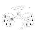
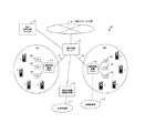
- 108700040193 Adenylosuccinate lyases Proteins 0.000 description 8
- 238000005516 engineering process Methods 0.000 description 5
- 239000000969 carrier Substances 0.000 description 2
- 238000011161 development Methods 0.000 description 2
- 230000018109 developmental process Effects 0.000 description 2
- 230000010365 information processing Effects 0.000 description 2
- 238000013475 authorization Methods 0.000 description 1
- 238000010276 construction Methods 0.000 description 1
- 230000000694 effects Effects 0.000 description 1
- 238000009434 installation Methods 0.000 description 1
- 230000010354 integration Effects 0.000 description 1
- 230000000873 masking effect Effects 0.000 description 1
Images
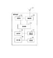
Classifications
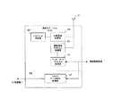
-
- H—ELECTRICITY
- H04—ELECTRIC COMMUNICATION TECHNIQUE
- H04L—TRANSMISSION OF DIGITAL INFORMATION, e.g. TELEGRAPHIC COMMUNICATION
- H04L12/00—Data switching networks
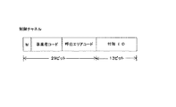
- H04L12/66—Arrangements for connecting between networks having differing types of switching systems, e.g. gateways
-
- H—ELECTRICITY
- H04—ELECTRIC COMMUNICATION TECHNIQUE
- H04W—WIRELESS COMMUNICATION NETWORKS
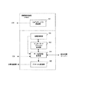
- H04W84/00—Network topologies
- H04W84/02—Hierarchically pre-organised networks, e.g. paging networks, cellular networks, WLAN [Wireless Local Area Network] or WLL [Wireless Local Loop]
- H04W84/10—Small scale networks; Flat hierarchical networks
- H04W84/16—WPBX [Wireless Private Branch Exchange]
-
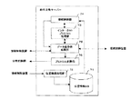
- H—ELECTRICITY
- H04—ELECTRIC COMMUNICATION TECHNIQUE
- H04L—TRANSMISSION OF DIGITAL INFORMATION, e.g. TELEGRAPHIC COMMUNICATION
- H04L12/00—Data switching networks
- H04L12/28—Data switching networks characterised by path configuration, e.g. LAN [Local Area Networks] or WAN [Wide Area Networks]
-
- H—ELECTRICITY
- H04—ELECTRIC COMMUNICATION TECHNIQUE
- H04M—TELEPHONIC COMMUNICATION
- H04M7/00—Arrangements for interconnection between switching centres
- H04M7/12—Arrangements for interconnection between switching centres for working between exchanges having different types of switching equipment, e.g. power-driven and step by step or decimal and non-decimal
- H04M7/1205—Arrangements for interconnection between switching centres for working between exchanges having different types of switching equipment, e.g. power-driven and step by step or decimal and non-decimal where the types of switching equipement comprises PSTN/ISDN equipment and switching equipment of networks other than PSTN/ISDN, e.g. Internet Protocol networks
-
- H—ELECTRICITY
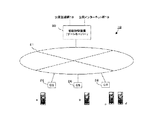
- H04—ELECTRIC COMMUNICATION TECHNIQUE
- H04Q—SELECTING
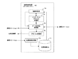
- H04Q3/00—Selecting arrangements
- H04Q3/58—Arrangements providing connection between main exchange and sub-exchange or satellite
-
- H—ELECTRICITY
- H04—ELECTRIC COMMUNICATION TECHNIQUE
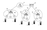
- H04W—WIRELESS COMMUNICATION NETWORKS
- H04W4/00—Services specially adapted for wireless communication networks; Facilities therefor
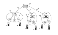
- H04W4/24—Accounting or billing
-
- H—ELECTRICITY
- H04—ELECTRIC COMMUNICATION TECHNIQUE
- H04M—TELEPHONIC COMMUNICATION
- H04M2207/00—Type of exchange or network, i.e. telephonic medium, in which the telephonic communication takes place
- H04M2207/18—Type of exchange or network, i.e. telephonic medium, in which the telephonic communication takes place wireless networks
-
- H—ELECTRICITY
- H04—ELECTRIC COMMUNICATION TECHNIQUE
- H04M—TELEPHONIC COMMUNICATION
- H04M2215/00—Metering arrangements; Time controlling arrangements; Time indicating arrangements
- H04M2215/20—Technology dependant metering
- H04M2215/2026—Wireless network, e.g. GSM, PCS, TACS
-
- H—ELECTRICITY
- H04—ELECTRIC COMMUNICATION TECHNIQUE
- H04M—TELEPHONIC COMMUNICATION
- H04M2215/00—Metering arrangements; Time controlling arrangements; Time indicating arrangements
- H04M2215/32—Involving wireless systems
-
- H—ELECTRICITY
- H04—ELECTRIC COMMUNICATION TECHNIQUE
- H04M—TELEPHONIC COMMUNICATION
- H04M7/00—Arrangements for interconnection between switching centres
- H04M7/009—Arrangements for interconnection between switching centres in systems involving PBX or KTS networks
Landscapes
- Engineering & Computer Science (AREA)
- Computer Networks & Wireless Communication (AREA)
- Signal Processing (AREA)
- Business, Economics & Management (AREA)
- Accounting & Taxation (AREA)
- Physics & Mathematics (AREA)
- Astronomy & Astrophysics (AREA)
- General Physics & Mathematics (AREA)
- Mobile Radio Communication Systems (AREA)
- Telephonic Communication Services (AREA)
- Data Exchanges In Wide-Area Networks (AREA)
- Sub-Exchange Stations And Push- Button Telephones (AREA)
Abstract
Description
【0001】
【発明の属する技術分野】
本発明は、携帯電話システムに関し、特に、複数の地域通信網を用い、地域通信網内あるいは各地域通信網間の通信をインターネット網を経由して行う携帯電話システムに関するものである。
【0002】
【従来の技術】
近年では、インターネット通信技術の発展に伴って、テキスト、音声、画像等の様々な情報を高速に送受信できるようになり、またインターネットへの接続も電話回線によるダイアルアップ接続から、低料金で常時インターネット網に接続可能なADSL技術へと発展してきており、利用者は世界中の任意のホームページから必要な情報を即座に取得することができ、また、インターネット網を利用した物品、コンテンツの販売を始め、各種の取引代金の決済、銀行取引、自治体のサービス等、インターネット網を利用した各種のサービスシステムが急速に発展し、インターネット技術は社会生活に欠くことのできないインフラになりつつある。
【0003】
一方、携帯電話に関する通信技術の発展にも目覚ましいものがあり、その基本機能である通話機能に加え、テキストデータや各種のデータファイルを送受信する電子メール機能や、iモード(登録商標名)として知られるインターネット接続機能を付加したサービスなどが各通信事業者によって競って実現されており、次々と新たなサービスが開発され、その性能アップと機能アップが図られている。
【0004】
従って、パーソナルコンピュータに代表されるインターネット網への接続機器と通信機器である携帯電話、固定電話(有線電話)はそれぞれの機能を複合的に合わせ持つ機器へと変化してきている。すなわち、パーソナルコンピュータはインターネット電話機としての機能を持ち、携帯電話は、電子メール機能やインターネット接続機器としての機能を持つようになりつつある。
【0005】
しかしながら、携帯電話により提供されている各種のサービスを受けるためには、その通話料金の負担が大きくなるという課題があり、パーナルコンピュータによるインターネット電話機能を利用する場合には、設置場所に固定したものになり、ノートタイプのパーソナルコンピュータを用いるとしても、機器の重量や大きさから、その携帯性、移動性には未だ課題が多い。
【0006】
一方、地域自治体や第3セクター方式で運営されるCATV網に代表される地域通信網も各地域で運営され、地域に密着したコンテンツの配信や、映画など、データ量の大きなコンテンツの配信サービスが行われている。しかしながら、CATVのような地域通信網においては、提供されるサービス(アプリケーション)が限られていることから、その加入者数に伸び悩みがあり、経営状況は必ずしも良好ではない。
【0007】
このような背景にあって、通話料金の安価なインターネット電話が脚光を浴びており、携帯電話への適用も種々提案されている。そして、第3世代、第4世代の携帯電話サービスが現実のものになるにつれ、インターネット網を利用した携帯電話の交換接続システムの重要性も増大していくものと考えられる。
【0008】
インターネット網を利用した携帯電話の交換接続システムの一例は、下記の特許文献1に「インターネットコードレス電話システム及びこのためのコードレス電話親機、コードレス電話子機ならびに接続制御装置」として開示されている。
【0009】
前記特許文献1に開示された技術は、インターネットプロトコルのもとで通信を行う複数のコードレス電話親機と、該コードレス電話親機と無線通信を行う1以上のコードレス電話子機であって、インターネットプロトコルに従う上位レイヤー処理部と無線通信プロトコルに従う下位レイヤー処理部とを有するコードレス電話子機と、前記コードレス電話子機のアドレス、および当該コードレス電話子機と通信を行うコードレス電話親機のアドレスを記憶し、インターネットプロトコルに従い前記コードレス電話親機を介して前記コードレス電話子機への、および前記コードレス電話子機からの接続および切断を制御する接続制御装置とから構成されている。
【0010】
そして、前記コードレス電話子機は、自機が位置するエリアに割り当てられているコードレス電話親機を介して、位置登録を前記接続制御装置に要求することにより、自機のインターネットプロトコル上のアドレスを前記接続制御装置に設定するとともに、前記アドレスの設定完了後、コードレス電話親機から自機宛ての着信があるまでの期間は前記下位レイヤー処理部の制御により、コードレス電話親機からの自機宛ての着信を間欠的に待ち受けるようになされている。
【0011】
【特許文献1】
特開2000−308128号公報
【0012】
【発明が解決しようとする課題】
しかしながら、前記の技術は、第1に、オフィス内、ビル内、本社・支社内及び全海外拠点間と地域電話会社間に固定のインターネット通信網を設定し、インターネット通信プロトコルに従う上位レイヤーと、無線通信プロトコルに従う下位レイヤーを持った複数のPHS親機、子機と接続制御装置を配し、PHS親機と子機間を自営モードで運用するものであって、PHS親機の配置されたエリアから安価な通話料金で、子機による受発信を可能とするが、その範囲が、固定的に設定されたインターネット通信網とPHS親機が配置されたエリアに限定されるという問題点がある。
【0013】
第2に、それぞれのPHS子機はIPアドレスを持ち、PHS親機との間で無線通信プロトコルに従って通信を行うための下位レイヤー処理部の他に、インターネットプロトコルに従う上位レイヤー処理部を追加する必要があり、PHS子機側のコスト増を招くという問題点があり、第3に、PHS子機がIPアドレスを持つことから、サービスを提供し得るPHS子機の数に制約が生ずるという問題点がある。
【0014】
第4に、各PHS子機はPHS親機との間で子機登録される必要があり、異なるエリアのPHS親機を通して通信するためには、全てのPHS子機が全てのPHS親機に対して子機登録される必要があるという問題点がある。
【0015】
このシステムを日本全国、あるいは、世界中のどこでも利用できるようにするためには、全地域をカバーする固定のインターネット通信網の設置、大量のPHS親機と子機の設置、それら大量の機器アドレスの管理と接続を行う接続制御装置の設置が必要となり、その構築には膨大な設備投資が必要になる。また、PHS子機にインターネットプロトコルに従う上位レイヤーの機能追加を必要とし、PHS親機には大量のPHS子機の子機登録を行う機能追加が必要になる。この機能追加はインターネットプロバイダーが提供するADSL接続サービス網のような地域通信網にPHS電話システムによるIP携帯電話サービスを適用する場合においても必要となる。
【0016】
従って、本発明は、前述のような従来技術の問題点を解決することを課題とし、既設の地域通信網を用い、インターネット網を経由して、日本全国、あるいは世界中のどこでも、膨大な設備投資なしに、安価な通話料金で通信が可能となる携帯電話システムを提供することを目的とし、また、PHS子機、PHS親機への機能追加を最小限にすることができ、インターネットプロバイダー等が提供する地域通信網にも好適に適合し得る携帯電話システムを提供することを目的とする。
【0017】
【課題を解決するための手段】
前記の本発明の目的は、以下の構成を採用することにより達成し得る。すなわち、本発明の第1の実施形態に係る地域通信網を用いた携帯電話システムは、複数の地域通信網にそれぞれ設置された接続制御装置と、各接続制御装置と私設インターネット網を介して接続された統合交換サーバーと、前記各接続制御装置に有線で接続され、地域通信網の加入者端末と併設されPHS親機として機能する複数の通信ステーションと、PHS子機として機能する複数の携帯端末とから構成される。
【0018】
そして、前記携帯端末は、少なくとも前記通信ステーションとの間で無線通信プロトコルに従って通信する無線部、通話部とを備え、
前記各通信ステーションは、自エリア内に位置する携帯端末の位置登録処理を行う位置登録処理部と、無線通信プロトコルに従って該携帯端末と通信を行う無線通信プロトコル処理部と、インターネットプロトコルに従って前記接続制御装置と通信を行うインターネットプロトコル処理部とを備え、
前記接続制御装置は、インターネット上のIPアドレスを有し、インターネットプロトコルに従って前記各通信ステーションおよび統合交換サーバーと通信を行うインターネットプロトコル処理部と、前記通信ステーションまたは統合交換サーバーからの通信データに従って接続制御を行う接続制御部とを備え、
前記統合交換サーバーは、前記接続制御装置のIPアドレスおよび各通信ステーションのIPアドレスと前記各携帯端末の位置情報を記憶する位置情報データベースと、インターネットプロトコルに従って前記各接続制御装置と通信を行うインターネットプロトコル処理部と、前記接続制御装置からの通信データに従って接続制御を行う接続制御部とを備え、前記通信データに基づいて位置情報データベースから取得した携帯端末の位置情報によって接続制御する。
【0019】
かかる地域通信網を用いた携帯電話システムによれば、各携帯端末と各通信ステーションとの間は通常のPHS自営モードの通信と同様に通話料金は無償であり、既存の地域通信網を利用して通信ステーション24〜28→接続制御装置22→統合交換サーバー12→接続制御装置32→通信ステーション34〜38の間は、インターネットプロトコルの通信を行うため、無償もしくは極めて安価な通話料金でのサービスが可能である。
【0020】
また、本発明に係る携帯電話システムによれば、前記接続制御装置は更に、前記通信ステーションまたは統合交換サーバーからの通信データをPSTN上のプロトコルに従ったデータに変換するプロトコル変換部を備え、前記接続制御部は公衆回線網を経由して着信先に接続可能となし、また、統合交換サーバーは更に、公衆インターネット網に接続可能に構成され、着信先がインターネット電話である場合に接続制御部は、該公衆インターネット網を経由して着信先に接続可能となし、更に、統合交換サーバーは、国際専用線事業者の設置する海外交換機に接続可能に構成され、着信先が公衆回線網加入者の携帯電話である場合に接続制御部は、該海外交換機を介して公衆回線網を経由して着信先に接続可能となしたことを特徴とする。
【0021】
かかる携帯電話システムによれば、公衆回線網加入者の固定電話あるいは携帯電話やインターネット電話のそれぞれに応じて、通話料金の最も安価なルートで接続制御することができる。
【0022】
更に、本発明に係る携帯電話システムによれば、統合交換サーバーは、海外に設置された統合交換サーバーと私設インターネット網を介して接続される。かかる構成により、サービスのエリアを容易に拡大でき、極めて安価な通話料金で国内のみならず海外への通話も可能となる。
【0023】
また、更に本発明に係る携帯電話システムによれば、地域通信網としてCATV通信網を用いることにより、CATVサービスに付加して携帯電話サービスが可能となり、CATVサービスへの加入者増加が可能となる。
更に本発明の第2の実施形態による地域通信網を用いた携帯電話システムは、地域通信網に設置された接続制御装置と、該接続制御装置とインターネット網を介して接続され、PHS親機として機能する複数の通信ステーションと、PHS子機として機能する複数の携帯端末とから構成され、
前記携帯端末は、少なくとも前記通信ステーションとの間で無線通信プロトコルに従って通信する無線部、通話部を備え、
前記各通信ステーションは、自エリア内に位置する携帯端末の位置登録処理を行う位置登録処理部と、無線通信プロトコルに従って該携帯端末と通信を行う無線通信プロトコル処理部と、インターネットプロトコルに従って前記接続制御装置と通信を行うインターネットプロトコル処理部とを備え、
前記接続制御装置は、前記通信ステーションのIPアドレスおよび各携帯端末の位置情報を記憶する位置情報データベースと、インターネットプロトコルに従って前記各接続制御装置と通信を行うインターネットプロトコル処理部と、前記通信ステーションからの通信データに従って接続制御を行う接続制御部とを備え、前記通信データに基づいて位置情報データベースから取得した携帯端末の位置情報によって接続制御することを特徴とする。
【0024】
かかる構成によれば、通信ステーション24〜28を多数設置することにより、インターネットプロバイダー等の地域通信網提供業者は、容易に安価なインターネット電話サービスを提供することができる。
また、本発明の第1または第2の実施形態の携帯電話システムにおいて、各通信ステーションは、更に、各通信ステーションに複数割り当てられ、当該通信ステーションを介して接続中の携帯端末に対して使用するIPアドレスを管理するIPアドレス管理部を備えたことを特徴とし、また、前記携帯端末は、更に、モード切換部を備え、該モード切換部によりIPモードを選択した場合において、前記通信ステーションから送信される制御チャネル情報中の所定ビット位置の情報をマスクして受信することを特徴とする
かかる携帯電話システムによれば、携帯端末としてのPHS子機にインターネットプロトコルに従う上位レイヤーを必要とせず、またPHS親機に大量のPHS子機の子機登録を行う必要もなくなり、またIPアドレスによる携帯端末数の制約を緩和することができ、多数の携帯端末に対するサービスが可能となる。
【0025】
以下、本発明に係る地域通信網を用いた携帯電話システムならびに地域通信網を用いた携帯電話システムについて添付の図面を参照して詳細に説明する。
【0026】
【発明の実施の形態】
図1は本発明の第1の実施形態に係る複数の地域通信網を用いた携帯電話システムの構成を示す図である。本発明に係る携帯電話システム10は、複数の地域通信網20、30にそれぞれ設置された接続制御装置(PBX)22、32と、各接続制御装置22、32と私設インターネット網14、16を介して接続された統合交換サーバー12と、各地域通信網20、30において、各接続制御装置22、32に有線で接続されたPHS親機として機能する通信ステーション(CS)24〜28、34〜38と、PHS子機として機能する携帯端末a〜hとから構成される。
【0027】
各地域通信網20、30に設置される接続制御装置22、32は、携帯端末a〜hからの呼の着信先が本携帯電話システムの加入者の携帯端末である場合には該着信先携帯端末が位置するエリアの接続制御装置、通信ステーションを経由して接続する。また、着信先が公衆回線網の加入者である場合には、着信先のアドレス変換、通信データのプロトコル変換等の機能(詳細は後述する)を持ち、公衆回線網19を経由して当該着信先に接続するよう構成される。
【0028】
統合交換サーバー12は、公衆インターネット網18に接続され、携帯端末a〜hからの呼の着信先がインターネット電話である場合には、公衆インターネット網18を経由して着信先が加入している事業者のゲートウエイに接続制御するように構成される。
【0029】
地域通信網としては、CATV通信網(CableTelevision通信網)、有線ブロードバンドサービス網、インターネットプロバイダーが提供するADSL接続サービス網やその他の通信網などの既存のインフラストラクチャーを利用することが可能である。
【0030】
地域通信網としてCATV通信網を利用する場合、各接続制御装置22、32は、地域通信網の各加入者端末(CATVアダプター)に向けて配信するコンテンツ等のCATVデータを送信するCATVサーバーと一体もしくは別体で併設され、各通信ステーション24〜28、34〜38も同様に、各加入者端末と一体もしくは別体で併設されるものであってよい。
【0031】
また、CATVサービスの空きチャネルを利用することにより、各通信ステーション24〜28、34〜38の機能と、加入者端末としてのCATVデータ受信処理機能を同時に動作させることができ、加入者端末あるいはTV受像機にCCDカメラ等を搭載し、通信ステーション24〜28、34〜38の親機として通話機能または携帯端末a〜hを併用してテレビ電話サービスを提供することも可能である。
【0032】
統合交換サーバー12は、インターネット上のIPアドレスを持ち、インターネットプロトコルに従う上位レイヤーの通信機能と、各接続制御装置22、32のインターネット上のIPアドレスと、各地域通信網内の各通信ステーション24〜28、34〜38のローカルアドレスを記憶するとともに、各携帯端末a〜hが通信ステーション24〜28、34〜38との間で行う位置登録の結果を記憶する位置情報データベースとを備える。
【0033】
各接続制御装置22、32は、それぞれ統合交換サーバー12および通信ステーション24〜28、34〜38と通信を行うためのインターネットプロトコルに従う上位レイヤーが付加され、それぞれがインターネット上のIPアドレスを持ち、また、通信ステーション24〜28、34〜38と各携帯端末a〜hとの間で行われる位置登録の結果を統合交換サーバー12に送信(中継)する。
【0034】
各通信ステーション24〜28、34〜38は、それぞれが複数のIPアドレスを持ち、それぞれ接続制御装置22、32と通信を行うためのインターネットプロトコルに従う上位レイヤーと、各携帯端末a〜hとの間で無線通信を行うための無線通信プロトコルに従う下位レイヤーを備え、また、接続中の携帯端末に対して使用するIPアドレスを管理するIPアドレス管理部を備え、PHS親機として機能するとともに、各携帯端末a〜hとの間で位置登録を行う基地局としての機能を有する。
【0035】
携帯端末a〜hは、インターネット上のIPアドレスを持たず、また、インターネットプロトコルに従う上位レイヤーを備える必要もなく、単に、PHS親機として機能する通信ステーション(CS)24〜28、34〜38との間で通信、および、位置登録する一般のPHS子機としての機能のみを有する。
【0036】
各接続制御装置22、32の機能は前述の如く、地域通信網における加入者に対するサービスを行うサーバー、例えば、CATV網である場合のCATVサーバーに付加されるものであってもよく、CATVサーバーと並立して動作する独立の装置として構成されるものであってもよい。
【0037】
また、各通信ステーション(CS)24〜28、34〜38は、地域通信網における加入者側に設置される通信アダプター、例えば、CATV網である場合のCATVアダプターに付加することによって構成され、各携帯端末a〜hとの間で通信および位置登録を行うためのアンテナを有するものであって、PHS親機としての通話機能は必ずしも必要がない。
【0038】
統合交換サーバー12および地域通信網における接続制御装置22、32を運用する事業体は、通信事業者としての登録、認可を必要とし、本発明による携帯電話サービスに加入する加入者が所有する携帯端末a〜hに付与する電話番号の割り当てを受ける必要がある。現在、全国番号計画において検討されているIP電話番号を適用することも可能である。次に、各装置の構成と動作を説明する。
【0039】
(1)携帯端末
携帯端末a〜hの構成は図2に示すように、通常のPHS電話機と同様であり、アンテナ41、無線部42、通話部43、制御部44、操作部45、表示部46、充電部48、モード切換部47とから構成されている。各部の機能、動作もPHS電話機と全く同じである。なお、この携帯端末を本携帯電話システム専用として用いる場合、自営モードのみで動作するものでよいが、本携帯電話サービス加入の携帯端末として後述する如きIPモード(IP電話モード)の動作を行うことが必要である。
【0040】
(2)通信ステーション(CS)
通信ステーション24〜28、34〜38は、地域通信網20、30のエリアにおいて自身を通して接続中の携帯端末a〜hに対して使用できる複数のIPアドレスをそれぞれが持ち、図3に示すように、PHS親機として機能し、携帯端末と無線通信プロトコルに従って通信する無線通信プロトコル処理部52およびアンテナ51と、接続制御装置22、32とインターネットプロトコルに従って通信するインターネットプロトコル処理部53とを備えるとともに、携帯端末の位置登録を行う位置登録処理部54と、接続中の携帯端末に対して使用するIPアドレスを管理するIPアドレス管理部57を備えて構成されている。
【0041】
位置登録処理によって、当該通信ステーション24〜28、34〜38自身のエリア内にある携帯端末a〜hの情報は、各接続制御装置22、32を介して、統合交換サーバー12に送られ、位置情報データベースに記憶される。この位置登録の処理は、通常の携帯電話システム、PHS電話システムと全く同様であり、携帯端末は、通信ステーション24〜28、34〜38に位置登録すると、着信待ち受け状態に入る。また、通話中の携帯端末a〜hが移動をする場合、従来のPHSシステムと同様にハンドオーバー処理を行うことができる。
【0042】
IPアドレス管理部57は通信ステーションが自身を通じて接続中(発信または着信)の携帯端末に対して一時的に割り当てて使用中のIPアドレスを管理するためのものであり、例えば、各通信ステーション24〜28、34〜38はそれぞれ3つのIPアドレスを持っており、自身を通じて接続中の携帯端末a〜hに一時的に特定のIPアドレスを割り当てて使用するため、接続中の携帯端末の端末装置番号あるいは携帯端末の電話番号と、該携帯端末に割り当てたIPアドレスの対応関係を一時記憶し、使用中および空きのIPアドレスを管理するものである。これにより、各通信ステーション24〜28、34〜38は自身を通して、複数の携帯端末の接続を時分割で行うことができる。
【0043】
一般に接続制御装置22、32と各通信ステーション24〜28、34〜38とのデータ通信速度は128kbp/sであり、通信ステーョン24〜28、34〜38と各携帯端末a〜hとのデータ通信速度は32kbp/sであるから、各通信ステーション24〜28、34〜38は3スロットのデータ通信チャネルを時分割で使用することができ、3つのIPアドレスを持つように構成することが好ましい。
【0044】
各携帯端末a〜hは各通信ステーション24〜28、34〜38に子機登録する必要はなく、携帯端末自身が位置するエリアの通信ステーションに接続することができる。従って、通信ステーションを設置したユーザーが所有する携帯端末が優先的にサービスを受けられるようにすることが好ましく、その場合、IPアドレス管理部に57に該通信ステーションを設置したユーザーが所有する携帯端末のID(携帯端末番号等)を登録しておき、他の携帯端末より優先して接続時に優先してIPアドレスを割り当てる優先制御機能を付加することが好ましい。
【0045】
図4は携帯端末a〜hと通信ステーション24〜28、34〜38との間の通信における制御チャネルフレームの概略構成を示す図である、この制御チャネルフレームは、計29ビットで構成されるモード切換えビットM(自営モードと公衆モードの切換)、事業者コード(サービスを提供する通信事業者のコード)および呼出しエリアコードと、13ビットの付加IDから構成される発識別符号と、図示していない28ビットの着識別符号(着信先携帯端末呼出し符号)とから構成されている。
【0046】
携帯端末a〜hを本サービスによるIP電話として動作させる時は、IPモード(IP電話モード)に切換える。すると携帯端末は、前記の事業者コード、呼出エリアコードの内上位の所定ビットを受信するように残りのビットをマスクして着信待ち受けを行い、発信の場合は自営モードと同様の動作を行う。従って、携帯端末a〜hのモード切換部47は公衆モード、自営モード、IPモード(IP電話モード)とトランシーバモード(子機同士の無線通話)の4モードの切換を行う。公衆モードを必要としない構成とする場合は自営モードとIPモードの切換機能のみでよい。これによって通信ステーション24〜28、34〜38は、携帯端末a〜hを子機として認識して接続制御する。従って、各携帯端末a〜hは、どのエリアに移動しても、当該エリアの通信ステーション24〜28、34〜38の子機として動作することができる。
【0047】
この第1の実施形態における携帯電話システム10は、例えばCATV通信網の如き地域通信網を利用するため、各通信ステーション24〜28、34〜38はCATVデータを受信しTV受像機に送信するCATVデータ受信処理部56を持つCATV受信アダプター55の機能に付加されるものである。
【0048】
すなわち、通信ステーション24〜28、34〜38は、CATV加入者毎にその家庭やビル等に設置される通信アダプター(CATVアダプター)55に本携帯電話システムとしての機能(携帯端末との間での親機としての機能)を付加したものである。なお、図3の通信ステーションはCATVアダプターと一体に構成した例を示しているが、前述の如く、通信ステーションとCATVアダプターとは必ずしも一体である必要はなく、物理的に別体として構成してもよい。
【0049】
(3)接続制御装置(PBX:PrivateBranch Exchange)
接続制御装置22、32は、地域通信網の加入者側に設置される加入者端末であるCATVアダプターに付加された通信ステーション24〜28、34〜38に対してCATVデータを送信(サービス)するためのCATVサービス処理部61と併設されるものであって、当該地域通信網内の各通信ステーション24〜28、34〜38に位置登録している携帯端末a〜hに対し、各通信ステーションからのまたは各通信ステーションへの通話の接続制御を行う。
【0050】
従って、各接続制御装置22、32は、図5に示すように統合交換サーバー12および各通信ステーション24〜28、34〜38とインターネットプロトコルに従って通信するインターネットプロトコル処理部62を備え、インターネット上のアドレスであるIPアドレスを持つとともに、各通信ステーション24〜28、34〜38に位置登録された携帯端末a〜hからの発信または携帯端末a〜hへの着信の接続制御を行う接続制御部63と、通話データを送受信するデータ送受信処理部64を有し、本携帯電話システム加入者でない公衆回線網接続の加入者(固定電話もしくは携帯電話)への接続のため、通話データをPSTN上のプロトコルに変換するプロトコル変換部65を有する。
【0051】
接続制御部63は、各通信ステーション24〜28、34〜38に位置登録され、待ち受け状態にある携帯端末a〜hに対する着信の場合、インターネットプロトコル処理部62は、統合交換サーバー12から送られてくる通信データ(通話データ)に含まれる通信ステーション24〜28、34〜38のIPアドレスに従って、接続制御し、データ送受信処理部64を介して、当該通信ステーション24〜28、34〜38に通信データ(着信先アドレス等の制御チャネル、通話データ等のデータチャネル)を送出する。
【0052】
また、接続制御部63は、本携帯電話システムの加入者でない、公衆回線網接続の加入者電話に対する着信の場合、着信先アドレス変換処理を行うとともに、プロトコル変換部65で通話データをPSTN上のプロトコルに従った通話データに変換する制御を行い、公衆回線網を経由して着信先に接続する。このプロトコル変換は、既存のインターネット電話システム等におけるプロトコル変換機能を流用することができる。
【0053】
また、各通信ステーション24〜28、34〜38のエリア内にある携帯端末a〜hからの発信の場合、データ送受信処理部64を介して統合交換サーバー12に通話データを送出し、統合交換サーバー12において、着信先に応じた接続制御が行われる。着信先が本携帯電話システム加入者の場合は、当該着信先携帯端末の位置情報に基づいて、該当する地域の接続制御装置22、32に接続制御する。
【0054】
着信先が公衆回線網接続の加入者電話であった場合、図7の拡大システム構成に示す海外交換機(国際専用線交換機)13、または、当該着信先に最も近い地域通信網の接続制御装置22、32を経由して公衆網19に接続するため、接続先(着信先)アドレスの変換を行いルーティングする。
【0055】
(4)統合交換サーバー
統合交換サーバー12は、図6に示すように、接続制御装置22、32のIPアドレスおよび通信ステーション24〜28、34〜38の地域通信網のエリア内のIPアドレスを記憶するとともに、各通信ステーション24〜28、34〜38と携帯端末a〜hとの間で行われる位置登録処理の結果を記憶する位置情報データベース(位置情報DB)71を備えている。各携帯端末a〜hの位置情報はそれぞれの位置登録を行った通信ステーション24乃至28、34乃至38から、各接続制御装置22、32を介して、統合交換サーバー12に集められ、位置情報処理部72により位置情報DB71に記憶される。
【0056】
また、統合交換サーバー12は、各接続制御装置22、32あるいは後述する図7に示す海外の統合交換サーバー12’、公衆インターネット網18、海外交換機(国際専用線交換機)13等と通信を行うため、インターネットプロトコルに従って通信するインターネットプロトコル処理部73を備え、インターネット上のアドレスであるIPアドレスを持つとともに、位置情報DB71に記憶された各携帯端末a〜hの位置情報に基づいて、携帯端末からの発信または携帯端末への着信の接続制御を行う接続制御部74と、各接続制御装置22、32あるいは海外の統合交換サーバー12’、公衆インターネット網18、海外交換機(国際専用線)13を介して送受信される通信データの送受信処理を行うデータ送受信処理部75を有する。
【0057】
更に、統合交換サーバー12は、本携帯電話システム加入者でない公衆回線網接続の加入者への接続のため、通話データをPSTNプロトコルに変換するプロトコル変換部76を備え、該加入者の電話への着信があった場合、接続制御部74により着信先アドレス変換処理を行い公衆網回線に接続し、データ送受信処理部75を経由する通信データをプロトコル変換部76でPSTN上のプロトコルに従った通信データにプロトコル変換し、公衆回線網を経由して着信先に送出する。
【0058】
前述したように、各通信ステーション24〜28、34〜38に位置登録し、待ち受け状態にある携帯端末a〜hに対する着信の場合、接続制御部74は、データ送受信処理部75で受信したデータ中の着信先アドレスに基づいて位置情報DB71から、当該携帯端末a〜hの位置情報を取得し、位置登録している該当地域の接続制御装置22、32、通信ステーション24〜28、34〜38を特定し、ルーティングを行い、着信先アドレスを変換してデータを送出する。
【0059】
一方、各通信ステーション24〜28、34〜38のエリアにある携帯端末a〜hからの発信の場合、接続制御部74は、データ送受信処理部75で受信したデータから着信先アドレスを取得し、着信先に応じた接続制御を行う。着信先が本携帯電話システム加入者の場合は、前記と同様、当該着信先携帯端末の位置情報に基づいて、該当地域の接続制御装置24〜28、34〜38に接続する。着信先が公衆回線接続の加入者電話であった場合、海外交換機(国際専用線交換機)13(図7参照)、または、当該着信先に最も近い地域通信網の接続制御装置24〜28、34〜38を経由して公衆回線網に接続するために、前記の経由する機器のアドレスを含む着信先アドレスへの変換(ルーティング)を行う。
【0060】
図7は、図1の携帯電話システムの更なる拡大構成を示す図であり、例えば、外国にも同様の携帯電話システムを構築し、その統合交換サーバー(海外)12’と国内の統合交換サーバー12とをインターネット網で接続して、接続サービスの範囲を容易に拡大することができる。また、本携帯電話システムの加入者でない、公衆回線網接続の加入者に対する接続を行うために、国際フリーダイアル等、海外の国際専用線事業者が設置する海外交換機、例えば、米国内の国際専用線交換機13とインターネット接続し、該米国内交換機13を経由して公衆回線網17に接続し、目的の加入者への接続を行うように構成することができる。
【0061】
以上説明した携帯電話システム10における携帯端末a〜h、例えば携帯端末aからの呼の着信先別にそのルーティングを整理して説明すると次の如くなる。すなわち、
(a)着信先が本携帯電話システムの携帯端末の場合、
例えば、着信先の携帯端末hが通信ステーション38のエリア内にあり位置登録されているものとすると、発信元携帯端末a→発信元携帯端末aが位置するエリアの通信ステーション24→接続制御装置22→統合交換サーバー12→接続制御装置32→通信ステーション38→携帯端末hとなる。携帯端末aと通信ステーション24、通信ステーション38と携帯端末hとの間は、無線通信プロトコルに従った通信が行われ、通信ステーション24によってインターネットプロトコルへのプロトコル変換が行われ、通信ステーション24から通信ステーション38までの間はインターネットプロトコルに従った通信が行われ、通信ステーション38によってインターネットプロトコルから無線通信プロトコルへのプロトコル変換が行われる。
【0062】
この場合の通話料金は、携帯端末aと通信ステーション24、通信ステーション38と携帯端末hとの間は通常のPHS自営モードの通信と同様に無償であり、通信ステーション24→接続制御装置22→統合交換サーバー12→接続制御装置32→通信ステーション38との間は、既存の地域通信網を利用するため、ほぼ無償に近い通話料金でのサービスが可能である。
【0063】
(b)着信先が公衆回線網の加入者固定電話の場合、
発信元携帯端末a→通信ステーション24→接続制御装置22→統合交換サーバー12→着信先固定電話の位置する地域(着信先固定電話に直近)の接続制御装置、例えば接続制御装置32→公衆回線網19→着信先固定電話となる。前述と同様、携帯端末aと通信ステーション24との間は、無線通信プロトコルに従った通信が行われ、通信ステーション24から着信先加入電話の直近の接続制御装置32までの間はインターネットプロトコルに従った通信が行われ、公衆網19に接続する時点で、インターネットプロトコルからPSTN上のプロトコルにプロトコル変換される。
【0064】
この場合の通話料金は、前記と同様、携帯端末aと通信ステーション24との間は無償であり、通信ステーション24→接続制御装置22→統合交換サーバー12→着信先固定電話の位置する地域の接続制御装置32までの通話料金は、既存の地域通信網を利用するためほぼ無償にでき、公衆回線網19による市内通話料金のみに近い通話料金にすることができる。
【0065】
(c)着信先が公衆回線網加入の携帯電話の場合、
発信元携帯端末a→通信ステーション24→接続制御装置22→統合交換サーバー12→国際フリーダイアル等の国際専用線事業者が設置する海外交換機13→公衆回線網17→着信先携帯電話となる。前述と同様、携帯端末aと通信ステーション24との間は、無線通信プロトコルに従った通信が行われ、通信ステーション24から海外交換機13までの間はインターネットプロトコルに従った通信が行われ、公衆回線網17に接続する時点でPSTN上のプロトコルに従った通信データへのプロトコル変換が行われる。
【0066】
この場合の通話料金は、前記と同様に、携帯端末aと通信ステーション24との間は無償であり、通信ステーション24→接続制御装置22→統合交換サーバー12→海外交換機13までの通話料金もほぼ無償にでき、国際専用線事業者の設定する通話料金のみに近い通話料金にすることができる。
【0067】
(d)着信先がインターネット電話(IP電話)の場合、
発信元携帯端末a→発信元携帯端末aが位置するエリアの通信ステーション24→接続制御装置22→統合交換サーバー12→公衆インターネット網18→着信先IP電話端末が加入する事業者のゲートウエイ→着信先IP電話端末となる。前述と同様、携帯端末aと通信ステーション24との間は、無線通信プロトコルに従った通信が行われ、通信ステーション24から着信先IP電話端末までインターネットプロトコルに従った通信が行われる。
【0068】
この場合の通話料金は、前記と同様に、携帯端末aと通信ステーション24との間は無償であり、通信ステーション24→接続制御装置22→統合交換サーバー12→公衆インターネット網18→着信先IP電話端末が加入する事業者のゲートウエイ→着信先IP電話端末までの間はインターネット電話の通話料金となる。
【0069】
図8は本発明の第2の実施形態を示す地域通信網を用いた携帯電話システム10の構成を示す図である。この実施形態は第1の実施形態における通信ステーション(CS)24〜28および携帯端末a〜dを、インターネットプロバイダーが提供する地域通信網21、例えばADSL接続サービス網に適用した場合のシステム構成を示す図である。
【0070】
図8において、各携帯端末a〜dの構成は図2に示す構成と同様でありその機能および動作の説明は重複するため省略する。また、通信ステーション(CS)24〜28の構成は基本的に図3に示す構成と同様であるが、本実施形態においてはCATV通信網等の地域通信網を用いる形態でないため、CATV受信アダプタ55の部分は不要となり、その他の構成、機能、動作は図3と同様である。勿論CATV網を用いる場合と同様、ADSL接続を用いてインターネットによるデータ通信を行うパーソナルコンピュータに併設することもでき、この場合はADSL通信アダプタでCATV受信アダプタ55の部分を置換えればよい。
【0071】
接続制御装置(ゲートキーパー)80は、図9に示すように、通信ステーション24〜28のIPアドレスおよび通信ステーション24〜28のIPアドレスを記憶するとともに、各通信ステーション24〜28と携帯端末a〜hとの間で行われる位置登録処理の結果を記憶する位置情報データベース(位置情報DB)71を備えている。各携帯端末a〜hの位置情報はそれぞれの位置登録を行った通信ステーション24〜28から接続制御装置(ゲートキーパー)80に集められ、位置情報処理部72により位置情報DB71に記憶される。
【0072】
また、接続制御装置(ゲートキーパー)80は、各通信ステーション24〜28あるいは公衆インターネット網18、公衆回線網19等と通信を行うため、インターネットプロトコルに従って通信するインターネットプロトコル処理部73を備え、インターネット上のアドレスであるIPアドレスを持つとともに、位置情報DB71に記憶された各携帯端末a〜dの位置情報に基づいて、携帯端末からの発信または携帯端末への着信の接続制御を行う接続制御部74と、各通信ステーション24〜28あるいは公衆インターネット網18、公衆回線網19を介して送受信される通信データの送受信処理を行うデータ送受信処理部75を有する。
【0073】
更に、接続制御装置(ゲートキーパー)80は、本携帯電話システム加入者でない公衆回線網接続の加入者への接続のため、通話データをPSTNプロトコルに変換するプロトコル変換部76を備え、該加入者の電話への着信があった場合、接続制御部74により着信先アドレス変換処理を行い公衆網回線18に接続し、データ送受信処理部75を経由する通信データをプロトコル変換部76でPSTN上のプロトコルに従った通信データにプロトコル変換し、公衆回線網18を経由して着信先に送出する。接続制御装置(ゲートキーパー)80の機能および動作は、図1の実施形態における統合交換サーバー12と基本的に同じであり、説明は重複するため省略する。
【0074】
このような携帯電話システム10によれば、通信ステーション24〜28を多数の設置することにより、インターネットプロバイダー等の地域通信網提供業者は、容易に安価なインターネット電話サービスを提供することができる。また、図1のシステムにおける単一の地域通信網20あるいは30が本携帯電話サービスを提供する場合は図8と同様のシステム構成となる。
【0075】
なお、図8の携帯電話システムにおいて、他のインターネットプロバイダーがサービスを提供している地域通信網を統合する場合は、それぞれの通信網の接続制御装置(ゲートキーパー)80の機能を図4の接続制御装置22、32に置換え、各地域通信網を統合するための統合交換サーバー12(図6)を設置すれば図1の携帯電話システムと同様のシステムを構築することができる。
【0076】
図10は、図1に示す第1の実施形態の携帯電話システムと図8に示す第2の実施形態の携帯電話システム間で通話を行うシステム構成を示す図である。図10に示すように、地域通信網20および30等を統合交換サーバー12で統合した携帯電話システムと、インターネットプロバイダーが提供するADSL接続サービス網21を地域通信網として用いた携帯電話システムは、統合交換サーバー12と接続制御装置(ゲートキーパー)80とが公衆インターネット網19の接続ポイントを介して相互に携帯端末a〜f間の通話を接続することができる。
【0077】
この場合、両携帯電話システムを運営する通信事業者が異なるため、一方の通信事業者のサービスに加入している携帯端末は他方の通信事業者が設置した通信ステーションCSに接続することはできない。例えば、図10で携帯端末a、bは地域通信網20、30に設置された通信ステーションCSに接続することはできず、携帯端末c〜fは地域通信網21に設置された通信ステーションCSには接続できない。勿論、両システムの地域通信網が物理的な地域に重複して設置されており、両システムの通信ステーションCSが近接して設置されていれば、それぞれの通信ステーションCSに接続され通話に支障をきたすことはない。
【0078】
図11は、図1に示す第1の実施形態の携帯電話システムと図8に示す第2の実施形態の携帯電話システムを更に統合した携帯電話システムの構成を示す図である。このシステムの場合、図11に示すように両携帯電話システムを運営する通信事業者が異なっても、接続制御装置(ゲートキーパー)80を私設インターネット網15を介して統合交換サーバー12に接続し、該統合交換サーバー12に各携帯端末a〜h(両携帯電話システムのサービスに加入している携帯端末)の位置登録情報を集約すればよい。この場合、統合交換サーバー12は、国家レベルで設置、運営することが好ましい。
【0079】
【発明の効果】
以上詳細に説明したように、本発明に第1の実施形態に係る携帯電話システムによれば、各携帯端末と各通信ステーションとの間は通常のPHS自営モードの通信と同様に通話料金は無償であり、既存の地域通信網を利用して通信ステーション→接続制御装置22→統合交換サーバー12→接続制御装置32→通信ステーションの間は、インターネットプロトコルの通信を行うため、無償もしくは極めて安価な通話料金でのサービスが可能である。
【0080】
また、本発明の第2の実施形態に係る携帯電話システムによれば、通信ステーション22〜26を多数設置することにより、インターネットプロバイダー等の地域通信網提供業者は、容易に安価なインターネット電話サービスを提供することができる。
【0081】
また、本発明の第1および第2の実施形態に係る携帯電話システムによれば、それぞれの携帯端末はIPアドレスを持たず、通信ステーションとの間でインターネットプロトコルに従う通信を行うための上位レイヤー処理部を必要とせず、コスト増を招くことがない。また、携帯端末がIPアドレスを持たず、IPアドレスの管理を通信網の上位(統合交換サーバー、接続制御装置等)で管理するため、サービスを提供し得る携帯端末の数に対する制約が緩和され、携帯端末数や通信ステーションの設置数も増大することができ、また、携帯端末と通信ステーションとの間で子機登録を行う必要もない。更に、各通信ステーションの一斉呼出しエリアを拡大することができるから、携帯端末が位置登録する頻度を減少させることができ、携帯端末の電池切れ頻度を少なくすることもできる。
【図面の簡単な説明】
【図1】本発明の第1の実施形態に係る携帯電話システムの概略構成を示す図である。
【図2】図1の携帯電話システムにおける加入者の携帯端末の構成を示す図である。
【図3】図1の携帯電話システムにおける通信ステーションの構成を示す図である。
【図4】図1における携帯端末と通信ステーションとの間の通信における制御チャネルフレームの概略構成を示す図である。
【図5】図1の携帯電話システムにおける接続制御装置の構成を示す図である。
【図6】図1の携帯電話システムにおける統合交換サーバーの構成を示す図である。
【図7】図1の実施形態に係る拡大された携帯電話システムの概略構成を示す図である。
【図8】本発明の第2の実施形態に係る携帯電話システムの概略構成を示す図である。
【図9】図8の携帯電話システムにおけるゲートキーパーの構成を示す図である。
【図10】第1の実施形態の携帯電話システムと第2の実施形態の携帯電話システム間で通話を行うシステム構成を示す図である。
【図11】第1および第2の実施形態の携帯電話システムを統合したシステム構成を示す図である。
【符号の説明】
10…携帯電話システム
12…統合交換サーバー
12’…海外統合交換サーバー
13…海外交換機
14、15、16…私設インターネット網
17、19…公衆回線網
18…公衆インターネット網
21…地域通信網(ADSL接続サービス網)
20、30…地域通信網
22、32…接続制御装置(PBX)
24、26、28…通信ステーション(CS)
34、36、38…通信ステーション(CS)
a〜h…携帯端末
41、51…アンテナ
42…無線部
43…通話部
52…無線通信プロトコル処理部
53…インターネットプロトコル処理部
54…位置登録処理部
55…CATV受信アダプター
56…CATVデータ受信処理部
57・・・IPアドレス管理部
61…CATVサービス処理部
62…インターネットプロトコル処理部
63…接続制御部
64…データ送受信処理部
65…プロトコル変換部
71…位置情報DB
72…位置情報処理部
73…インターネットプロトコル処理部
74…接続制御部
75…データ送受信処理部
76…プロトコル変換部
80…接続制御装置(ゲートキーパー)[0001]
TECHNICAL FIELD OF THE INVENTION
The present invention relates to a mobile phone system, and more particularly, to a mobile phone system that uses a plurality of regional communication networks and performs communication within a regional communication network or between regional communication networks via an Internet network.
[0002]
[Prior art]
In recent years, with the development of Internet communication technology, various types of information such as text, voice, images, etc. can be transmitted and received at high speed. Has been evolving into ADSL technology that can be connected to the Internet, users can immediately obtain necessary information from any homepage in the world, and also start selling goods and contents using the Internet network, Various service systems using the Internet network, such as settlement of various transaction prices, bank transactions, services of local governments, etc., are rapidly developing, and Internet technology is becoming an indispensable infrastructure for social life.
[0003]
On the other hand, there have been remarkable developments in communication technology related to mobile phones. In addition to the basic function of the communication function, the e-mail function for sending and receiving text data and various data files, and the i-mode (registered trademark) name are also known. Services with an added Internet connection function are being realized by each telecommunications carrier in competition, and new services are being developed one after another, and their performance and functions are being improved.
[0004]
Accordingly, devices connected to the Internet, such as personal computers, and mobile phones and fixed phones (wired phones), which are communication devices, are changing to devices that have their respective functions combined. That is, a personal computer has a function as an Internet telephone, and a mobile phone has an electronic mail function and a function as an Internet connection device.
[0005]
However, in order to receive various services provided by the mobile phone, there is a problem that the burden of the call fee becomes large, and when using the Internet telephone function by the personal computer, it is fixed at the installation location. Therefore, even if a notebook personal computer is used, there are still many problems in portability and mobility due to the weight and size of the device.
[0006]
On the other hand, a regional communication network represented by a local government or a CATV network operated in the third sector system is also operated in each region, and a distribution service for contents with a large amount of data such as distribution of contents closely related to the region and movies. Is being done. However, in a regional communication network such as CATV, provided services (applications) are limited, the number of subscribers is stagnant, and the business situation is not always good.
[0007]
Against this background, inexpensive Internet telephones have been in the spotlight, and various applications to mobile phones have been proposed. As the third and fourth generation mobile phone services become real, the importance of a mobile phone switching connection system using the Internet network is expected to increase.
[0008]
An example of a mobile phone exchange connection system using the Internet network is disclosed in Patent Document 1 below as "Internet cordless telephone system and cordless telephone master unit, cordless telephone slave unit, and connection control device therefor".
[0009]
The technique disclosed in Patent Document 1 includes a plurality of cordless telephone base units performing communication under the Internet protocol, and one or more cordless telephone slave units performing wireless communication with the cordless telephone base unit. A cordless telephone handset having an upper layer processing unit according to a protocol and a lower layer processing unit according to a wireless communication protocol, an address of the cordless telephone handset, and an address of a cordless telephone base unit communicating with the cordless telephone handset. And a connection control device for controlling connection and disconnection to and from the cordless telephone slave via the cordless telephone master according to the Internet protocol.
[0010]
Then, the cordless telephone handset requests its connection control device for location registration through the cordless telephone base station assigned to the area where the cordless telephone is located, thereby renewing its own address on the Internet protocol. While setting the connection control device, after the completion of the setting of the address, a period from when the cordless telephone base unit receives an incoming call to the own device, under the control of the lower layer processing unit, from the cordless telephone base unit to the own device. Is intermittently waiting for incoming calls.
[0011]
[Patent Document 1]
JP 2000-308128 A
[0012]
[Problems to be solved by the invention]
However, the above-mentioned technology firstly sets up a fixed Internet communication network between offices, buildings, headquarters / branches and all overseas bases and between local telephone companies, and establishes an upper layer according to the Internet communication protocol, A plurality of PHS master units having lower layers according to a communication protocol, a plurality of slave units, and a connection control device are arranged, and the PHS master unit and the slave unit are operated in a self-operating mode, and an area where the PHS master unit is arranged. , The receiving and transmitting by the slave unit is possible at a low call charge, but there is a problem that the range is limited to an area where the fixedly set Internet communication network and the PHS master unit are arranged.
[0013]
Secondly, each PHS slave has an IP address, and needs to add an upper layer processor according to the Internet protocol in addition to a lower layer processor for performing communication with the PHS master according to a wireless communication protocol. Third, there is a problem that the cost of the PHS slave is increased. Third, since the PHS slave has an IP address, the number of PHS slaves that can provide a service is restricted. There is.
[0014]
Fourth, each PHS slave needs to be registered with the PHS master, and in order to communicate through PHS masters in different areas, all PHS slaves must be registered with all PHS masters. On the other hand, there is a problem that the slave unit needs to be registered.
[0015]
In order to make this system available all over Japan or anywhere in the world, it is necessary to install a fixed Internet communication network covering all areas, install a large number of PHS base units and handset units, and a large number of device addresses It is necessary to install a connection control device that performs management and connection, and a huge capital investment is required for its construction. Further, the PHS slave requires an additional function of an upper layer according to the Internet protocol, and the PHS master needs a function of registering a large number of PHS slaves. The addition of this function is necessary even when the IP mobile telephone service by the PHS telephone system is applied to a local communication network such as an ADSL connection service network provided by an Internet provider.
[0016]
Accordingly, an object of the present invention is to solve the problems of the prior art as described above, and use an existing regional communication network via an Internet network to provide enormous facilities all over Japan or anywhere in the world. An object of the present invention is to provide a mobile phone system that enables communication at a low call rate without investment, and can minimize addition of functions to a PHS slave unit and a PHS base unit. It is an object of the present invention to provide a mobile phone system that can be suitably adapted to a regional communication network provided by the mobile phone.
[0017]
[Means for Solving the Problems]
The above object of the present invention can be achieved by employing the following configuration. That is, the mobile phone system using the local communication network according to the first embodiment of the present invention is connected to connection control devices installed in a plurality of local communication networks, respectively, and to each connection control device via a private Internet network. Integrated switching server, a plurality of communication stations connected by wire to the respective connection control devices, provided together with subscriber terminals of the local communication network, and functioning as PHS master units, and a plurality of mobile terminals functioning as PHS slave units It is composed of
[0018]
The mobile terminal includes a wireless unit that communicates with at least the communication station according to a wireless communication protocol, and a call unit,
Each of the communication stations includes a location registration processing unit that performs location registration processing of a mobile terminal located within its own area, a wireless communication protocol processing unit that communicates with the mobile terminal according to a wireless communication protocol, and the connection control according to an Internet protocol. An Internet protocol processing unit that communicates with the device,
The connection control device has an IP address on the Internet, communicates with each of the communication stations and the integrated switching server according to an Internet protocol, and controls connection according to communication data from the communication station or the integrated switching server. And a connection control unit for performing
The integrated exchange server includes: a location information database that stores an IP address of the connection control device, an IP address of each communication station, and location information of each mobile terminal; and an Internet protocol that communicates with each of the connection control devices according to an Internet protocol. A connection control unit that performs connection control in accordance with communication data from the connection control device, and performs connection control based on the location information of the mobile terminal obtained from a location information database based on the communication data.
[0019]
According to the mobile telephone system using such a local communication network, the communication fee between each mobile terminal and each communication station is free of charge as in the ordinary PHS private mode communication, and the existing local communication network is used. Since the
[0020]
According to the mobile phone system of the present invention, the connection control device further includes a protocol conversion unit that converts communication data from the communication station or the integrated switching server into data according to a protocol on PSTN. The connection control unit does not allow connection to the destination via the public line network, and the integrated switching server is further configured to be connectable to the public Internet network. When the destination is an Internet telephone, the connection control unit The integrated exchange server is configured to be connectable to an overseas exchange installed by an international private line carrier, and the destination is set to a public line network subscriber. In the case of a mobile phone, the connection control unit is capable of connecting to a destination via a public line network via the overseas exchange.
[0021]
According to such a mobile telephone system, connection control can be performed through a route having the lowest call fee according to each of a fixed telephone, a mobile telephone, and an Internet telephone of a public line network subscriber.
[0022]
Further, according to the mobile telephone system of the present invention, the integrated exchange server is connected to the integrated exchange server installed abroad via a private Internet network. With such a configuration, the service area can be easily expanded, and a call can be made not only at home but also abroad at an extremely low call rate.
[0023]
Further, according to the mobile phone system according to the present invention, by using a CATV communication network as a regional communication network, a mobile phone service can be provided in addition to the CATV service, and the number of subscribers to the CATV service can be increased. .
Further, the mobile telephone system using the local communication network according to the second embodiment of the present invention is a connection control device installed in the local communication network, connected to the connection control device via the Internet network, and used as a PHS master device. It comprises a plurality of communication stations that function and a plurality of mobile terminals that function as PHS slaves,
The mobile terminal includes a wireless unit that communicates with at least the communication station according to a wireless communication protocol, and a call unit.
Each of the communication stations includes a location registration processing unit that performs location registration processing of a mobile terminal located within its own area, a wireless communication protocol processing unit that communicates with the mobile terminal according to a wireless communication protocol, and the connection control according to an Internet protocol. An Internet protocol processing unit that communicates with the device,
The connection control device includes: a location information database that stores an IP address of the communication station and location information of each mobile terminal; an Internet protocol processing unit that communicates with each of the connection control devices according to an Internet protocol; A connection control unit that performs connection control according to the communication data, wherein the connection is controlled by the position information of the mobile terminal obtained from the position information database based on the communication data.
[0024]
According to such a configuration, by providing a large number of communication stations 24-28, a local communication network provider such as an Internet provider can easily provide an inexpensive Internet telephone service.
In the mobile phone system according to the first or second embodiment of the present invention, each communication station is further assigned to each communication station and used for a mobile terminal connected via the communication station. The portable terminal further includes an IP address management unit that manages an IP address, and the portable terminal further includes a mode switching unit, and when the IP mode is selected by the mode switching unit, transmission from the communication station is performed. Receiving information while masking information at a predetermined bit position in the control channel information to be transmitted.
According to such a mobile phone system, the PHS slave as a portable terminal does not require an upper layer according to the Internet protocol, does not need to register a large number of PHS slaves in the PHS master, and uses the IP address. The restriction on the number of mobile terminals can be alleviated, and services for a large number of mobile terminals can be provided.
[0025]
Hereinafter, a mobile phone system using a local communication network and a mobile phone system using a local communication network according to the present invention will be described in detail with reference to the accompanying drawings.
[0026]
BEST MODE FOR CARRYING OUT THE INVENTION
FIG. 1 is a diagram showing a configuration of a mobile phone system using a plurality of regional communication networks according to a first embodiment of the present invention. The mobile phone system 10 according to the present invention includes connection control devices (PBXs) 22 and 32 installed in a plurality of
[0027]
The
[0028]
The
[0029]
As the regional communication network, an existing infrastructure such as a CATV communication network (Cable Television communication network), a wired broadband service network, an ADSL connection service network provided by an Internet provider, and other communication networks can be used.
[0030]
When a CATV communication network is used as a local communication network, each of the
[0031]
Further, by using the unused channel of the CATV service, the function of each of the
[0032]
The
[0033]
Each
[0034]
Each of the
[0035]
The mobile terminals a to h do not have an IP address on the Internet and do not need to have an upper layer according to the Internet protocol, and simply communicate with the communication stations (CS) 24 to 28 and 34 to 38 functioning as PHS base units. It has only a function as a general PHS slave unit for communication between and a location registration.
[0036]
As described above, the functions of the
[0037]
Each of the communication stations (CS) 24 to 28 and 34 to 38 is configured by adding to a communication adapter installed on a subscriber side in a local communication network, for example, a CATV adapter in the case of a CATV network. It has an antenna for performing communication and location registration with the portable terminals a to h, and does not necessarily require the call function as the PHS master.
[0038]
The business entity that operates the integrated switching
[0039]
(1) Mobile terminal
As shown in FIG. 2, the configuration of the mobile terminals a to h is the same as that of a normal PHS telephone, and includes an
[0040]
(2) Communication station (CS)
Each of the communication stations 24-28 and 34-38 has a plurality of IP addresses that can be used for the mobile terminals a-h connected through the area in the area of the
[0041]
As a result of the location registration process, the information of the mobile terminals a to h in the area of the
[0042]
The IP
[0043]
Generally, the data communication speed between the
[0044]
Each of the mobile terminals a to h does not need to be registered in each of the
[0045]
FIG. 4 is a diagram showing a schematic configuration of a control channel frame in communication between the mobile terminals a to h and the
[0046]
When the mobile terminals a to h are operated as IP phones according to the present service, the mode is switched to an IP mode (IP phone mode). Then, the portable terminal masks the remaining bits so as to receive the higher-order predetermined bits of the carrier code and the calling area code and waits for an incoming call. In the case of calling, the portable terminal performs the same operation as in the self-service mode. Therefore, the
[0047]
Since the mobile phone system 10 according to the first embodiment uses a local communication network such as a CATV communication network, each of the
[0048]
That is, the communication stations 24-28 and 34-38 are provided with a communication adapter (CATV adapter) 55 installed in a home, a building, or the like for each CATV subscriber, as a function as the mobile phone system (for communication with a mobile terminal). (Function as a parent machine). Although the communication station in FIG. 3 shows an example in which the communication station and the CATV adapter are integrated, as described above, the communication station and the CATV adapter do not necessarily have to be integrated, but are physically configured separately. Is also good.
[0049]
(3) Connection control device (PBX: Private Branch Exchange)
The
[0050]
Accordingly, each of the
[0051]
The
[0052]
Further, in the case of an incoming call to a subscriber telephone connected to the public network, which is not a subscriber of the mobile phone system, the
[0053]
Further, in the case of a call from mobile terminals a to h in the area of each of the
[0054]
When the destination is a subscriber telephone connected to the public network, the overseas exchange (international private line exchange) 13 shown in the enlarged system configuration of FIG. 7 or the
[0055]
(4) Integrated exchange server
As shown in FIG. 6, the
[0056]
The
[0057]
Further, the
[0058]
As described above, in the case of an incoming call to the portable terminals a to h which are registered in the
[0059]
On the other hand, in the case of outgoing calls from the mobile terminals a to h in the areas of the
[0060]
FIG. 7 is a diagram showing a further enlarged configuration of the mobile phone system of FIG. 1. For example, a similar mobile phone system is constructed in a foreign country, and its integrated exchange server (overseas) 12 'and domestic integrated exchange server are used. 12 can be connected via the Internet network, and the range of the connection service can be easily expanded. In addition, in order to make connections to subscribers of the public line network who are not subscribers of this mobile phone system, international toll-free dials and other overseas exchanges set up by overseas dedicated line operators, for example, international exchanges in the United States It can be configured to connect to the line switch 13 via the Internet, connect to the public line network 17 via the U.S.A. switch 13, and connect to the intended subscriber.
[0061]
The routing will be described below according to the destinations of calls from the mobile terminals a to h, for example, the mobile terminal a in the mobile phone system 10 described above. That is,
(A) When the destination is a mobile terminal of the mobile phone system,
For example, assuming that the destination mobile terminal h is in the area of the
[0062]
In this case, the communication fee between the mobile terminal a and the
[0063]
(B) When the destination is a subscriber fixed telephone of a public line network,
Originating portable terminal a →
[0064]
In this case, the call charge is free between the portable terminal a and the
[0065]
(C) When the destination is a mobile phone subscribed to the public network,
The source mobile terminal a → the
[0066]
In this case, the call charge between the portable terminal a and the
[0067]
(D) When the destination is an Internet phone (IP phone),
Source portable terminal a →
[0068]
In this case, the call charge is free between the portable terminal a and the
[0069]
FIG. 8 is a diagram showing a configuration of a mobile phone system 10 using a local communication network according to a second embodiment of the present invention. This embodiment shows a system configuration when the communication stations (CS) 24 to 28 and the portable terminals a to d in the first embodiment are applied to a
[0070]
8, the configuration of each of the mobile terminals a to d is the same as the configuration shown in FIG. 2 and the description of the functions and operations is omitted because they are duplicated. The configuration of the communication stations (CS) 24 to 28 is basically the same as the configuration shown in FIG. 3. However, in this embodiment, since the present embodiment does not use a local communication network such as a CATV communication network, the CATV receiving adapter 55 is not used. Is unnecessary, and other configurations, functions, and operations are the same as those in FIG. Of course, as in the case of using the CATV network, it can be provided together with a personal computer that performs data communication via the Internet using an ADSL connection. In this case, the CATV receiving adapter 55 may be replaced with an ADSL communication adapter.
[0071]
As shown in FIG. 9, the connection control device (gate keeper) 80 stores the IP addresses of the
[0072]
The connection control device (gate keeper) 80 includes an Internet
[0073]
Further, the connection control device (gate keeper) 80 includes a
[0074]
According to such a mobile telephone system 10, by installing a large number of
[0075]
In the case of integrating the regional communication networks provided by other Internet providers in the mobile phone system of FIG. 8, the function of the connection control device (gate keeper) 80 of each communication network is changed to the connection of FIG. If the integrated switching server 12 (FIG. 6) for integrating each regional communication network is installed instead of the
[0076]
FIG. 10 is a diagram showing a system configuration for making a call between the mobile phone system of the first embodiment shown in FIG. 1 and the mobile phone system of the second embodiment shown in FIG. As shown in FIG. 10, a mobile phone system in which the
[0077]
In this case, since the carriers operating the two mobile phone systems are different, the mobile terminal subscribing to the service of one carrier cannot be connected to the communication station CS installed by the other carrier. For example, in FIG. 10, the mobile terminals a and b cannot connect to the communication stations CS installed in the
[0078]
FIG. 11 is a diagram showing a configuration of a mobile phone system in which the mobile phone system of the first embodiment shown in FIG. 1 and the mobile phone system of the second embodiment shown in FIG. 8 are further integrated. In the case of this system, the connection control device (gate keeper) 80 is connected to the
[0079]
【The invention's effect】
As described in detail above, according to the mobile phone system according to the first embodiment of the present invention, the communication fee between each mobile terminal and each communication station is free as in the ordinary PHS self-service mode communication. The communication between the communication station →
[0080]
Further, according to the mobile phone system according to the second embodiment of the present invention, by installing a large number of
[0081]
Further, according to the mobile phone systems according to the first and second embodiments of the present invention, each mobile terminal does not have an IP address and an upper layer process for performing communication with a communication station according to an Internet protocol. No parts are required, and there is no increase in cost. In addition, since the mobile terminal does not have an IP address and the management of the IP address is managed at a higher level of the communication network (integrated switching server, connection control device, etc.), restrictions on the number of mobile terminals that can provide services are relaxed, The number of mobile terminals and the number of communication stations can be increased, and there is no need to perform child device registration between the mobile terminal and the communication station. Furthermore, since the simultaneous call area of each communication station can be expanded, the frequency of location registration of the mobile terminal can be reduced, and the frequency of battery exhaustion of the mobile terminal can be reduced.
[Brief description of the drawings]
FIG. 1 is a diagram showing a schematic configuration of a mobile phone system according to a first embodiment of the present invention.
FIG. 2 is a diagram showing a configuration of a mobile terminal of a subscriber in the mobile phone system of FIG. 1;
FIG. 3 is a diagram showing a configuration of a communication station in the mobile phone system of FIG. 1;
FIG. 4 is a diagram showing a schematic configuration of a control channel frame in communication between the mobile terminal and the communication station in FIG. 1;
FIG. 5 is a diagram showing a configuration of a connection control device in the mobile phone system of FIG. 1;
FIG. 6 is a diagram showing a configuration of an integrated exchange server in the mobile phone system of FIG. 1;
FIG. 7 is a diagram illustrating a schematic configuration of an enlarged mobile phone system according to the embodiment of FIG. 1;
FIG. 8 is a diagram illustrating a schematic configuration of a mobile phone system according to a second embodiment of the present invention.
FIG. 9 is a diagram showing a configuration of a gatekeeper in the mobile phone system of FIG. 8;
FIG. 10 is a diagram illustrating a system configuration for performing a call between the mobile phone system according to the first embodiment and the mobile phone system according to the second embodiment;
FIG. 11 is a diagram showing a system configuration in which the mobile phone systems of the first and second embodiments are integrated.
[Explanation of symbols]
10. Mobile phone system
12 ... Integrated exchange server
12 '... Overseas integrated exchange server
13. Overseas exchange
14, 15, 16… Private Internet network
17, 19: Public line network
18 Public Internet Network
21: Regional communication network (ADSL connection service network)
20, 30 ... regional communication network
22, 32 ... Connection control device (PBX)
24, 26, 28 ... Communication station (CS)
34, 36, 38 ... Communication Station (CS)
ah: Mobile terminals
41, 51 ... antenna
42 ... Wireless unit
43… Call department
52 ... Wireless communication protocol processing unit
53 ... Internet protocol processing unit
54: Location registration processing unit
55 ... CATV receiving adapter
56: CATV data reception processing unit
57: IP address management unit
61: CATV service processing unit
62 Internet Protocol Processing Unit
63: connection control unit
64 Data transmission / reception processing unit
65: Protocol conversion unit
71 ... Location information DB
72 Position information processing unit
73 ... Internet protocol processing unit
74 connection control unit
75 Data transmission / reception processing unit
76: Protocol conversion unit
80 ... connection control device (gate keeper)
Claims (12)
前記携帯端末は、少なくとも前記通信ステーションとの間で無線通信プロトコルに従って通信する無線部、通話部を備え、
前記各通信ステーションは、自エリア内に位置する携帯端末の位置登録処理を行う位置登録処理部と、無線通信プロトコルに従って該携帯端末と通信を行う無線通信プロトコル処理部と、インターネットプロトコルに従って前記接続制御装置と通信を行うインターネットプロトコル処理部とを備え、
前記接続制御装置は、インターネット上のIPアドレスを有し、インターネットプロトコルに従って前記各通信ステーションおよび統合交換サーバーと通信を行うインターネットプロトコル処理部と、前記通信ステーションまたは統合交換サーバーからの通信データに従って接続制御を行う接続制御部とを備え、
前記統合交換サーバーは、前記接続制御装置のIPアドレスおよび各通信ステーションのIPアドレスと前記各携帯端末の位置情報を記憶する位置情報データベースと、インターネットプロトコルに従って前記各接続制御装置と通信を行うインターネットプロトコル処理部と、前記接続制御装置からの通信データに従って接続制御を行う接続制御部とを備え、前記通信データに基づいて位置情報データベースから取得した携帯端末の位置情報によって接続制御することを特徴とする地域通信網を用いた携帯電話システム。A connection control device installed in each of the plurality of regional communication networks, an integrated exchange server connected to each of the connection control devices via a private Internet network, and a wired connection to each of the connection control devices to join the regional communication network A plurality of communication stations that are provided in parallel with the remote terminal and function as a PHS base unit, and a plurality of mobile terminals that function as a PHS slave unit.
The mobile terminal includes a wireless unit that communicates with at least the communication station according to a wireless communication protocol, and a call unit.
Each of the communication stations includes a location registration processing unit that performs location registration processing of a mobile terminal located within its own area, a wireless communication protocol processing unit that communicates with the mobile terminal according to a wireless communication protocol, and the connection control according to an Internet protocol. An Internet protocol processing unit that communicates with the device,
The connection control device has an IP address on the Internet, communicates with each of the communication stations and the integrated switching server according to an Internet protocol, and controls connection according to communication data from the communication station or the integrated switching server. And a connection control unit for performing
The integrated exchange server includes: a location information database that stores an IP address of the connection control device, an IP address of each communication station, and location information of each mobile terminal; and an Internet protocol that communicates with each of the connection control devices according to an Internet protocol. A processing unit; and a connection control unit configured to perform connection control according to communication data from the connection control device, wherein connection control is performed based on position information of the mobile terminal acquired from a position information database based on the communication data. A mobile phone system using a regional communication network.
前記携帯端末は、少なくとも前記通信ステーションとの間で無線通信プロトコルに従って通信する無線部、通話部を備え、
前記各通信ステーションは、自エリア内に位置する携帯端末の位置登録処理を行う位置登録処理部と、無線通信プロトコルに従って該携帯端末と通信を行う無線通信プロトコル処理部と、インターネットプロトコルに従って前記接続制御装置と通信を行うインターネットプロトコル処理部とを備え、
前記接続制御装置は、前記通信ステーションのIPアドレスおよび各携帯端末の位置情報を記憶する位置情報データベースと、インターネットプロトコルに従って前記各接続制御装置と通信を行うインターネットプロトコル処理部と、前記通信ステーションからの通信データに従って接続制御を行う接続制御部とを備え、前記通信データに基づいて位置情報データベースから取得した携帯端末の位置情報によって接続制御することを特徴とする地域通信網を用いた携帯電話システム。A connection control device installed in a local communication network, a plurality of communication stations connected to the connection control device via the Internet network and functioning as a PHS master device, and a plurality of mobile terminals functioning as a PHS slave device And
The mobile terminal includes a wireless unit that communicates with at least the communication station according to a wireless communication protocol, and a call unit.
Each of the communication stations includes a location registration processing unit that performs location registration processing of a mobile terminal located within its own area, a wireless communication protocol processing unit that communicates with the mobile terminal according to a wireless communication protocol, and the connection control according to an Internet protocol. An Internet protocol processing unit that communicates with the device,
The connection control device includes: a location information database that stores an IP address of the communication station and location information of each mobile terminal; an Internet protocol processing unit that communicates with each of the connection control devices according to an Internet protocol; A mobile phone system using a regional communication network, comprising: a connection control unit that performs connection control according to communication data; and performing connection control based on position information of the mobile terminal obtained from a position information database based on the communication data.
Priority Applications (10)
| Application Number | Priority Date | Filing Date | Title |
|---|---|---|---|
| JP2002357306A JP4113766B2 (en) | 2002-07-05 | 2002-12-09 | Mobile phone system using regional communication network |
| BR0312583-1A BR0312583A (en) | 2002-07-05 | 2003-07-03 | Mobile phone system using local communication network, communication station and mobile terminal. |
| US10/520,159 US20050120071A1 (en) | 2002-07-05 | 2003-07-03 | Mobile telephone system using local communication network |
| MXPA05000356A MXPA05000356A (en) | 2002-07-05 | 2003-07-03 | Mobile telephone system using local communication network. |
| CN038158310A CN1666493A (en) | 2002-07-05 | 2003-07-03 | Mobile telephone system using local communication network |
| EP03738672A EP1528772A4 (en) | 2002-07-05 | 2003-07-03 | Mobile telephone system using local communication network |
| PCT/JP2003/008501 WO2004006552A1 (en) | 2002-07-05 | 2003-07-03 | Mobile telephone system using local communication network |
| AU2003246265A AU2003246265A1 (en) | 2002-07-05 | 2003-07-03 | Mobile telephone system using local communication network |
| KR1020057000210A KR100719192B1 (en) | 2002-07-05 | 2003-07-03 | Mobile Phone System Using Local Network |
| TW092118268A TWI251414B (en) | 2002-07-05 | 2003-07-04 | Mobile telephone system using a local area communication network |
Applications Claiming Priority (2)
| Application Number | Priority Date | Filing Date | Title |
|---|---|---|---|
| JP2002197774 | 2002-07-05 | ||
| JP2002357306A JP4113766B2 (en) | 2002-07-05 | 2002-12-09 | Mobile phone system using regional communication network |
Publications (3)
| Publication Number | Publication Date |
|---|---|
| JP2004088716A true JP2004088716A (en) | 2004-03-18 |
| JP2004088716A5 JP2004088716A5 (en) | 2005-07-14 |
| JP4113766B2 JP4113766B2 (en) | 2008-07-09 |
Family
ID=30117401
Family Applications (1)
| Application Number | Title | Priority Date | Filing Date |
|---|---|---|---|
| JP2002357306A Expired - Fee Related JP4113766B2 (en) | 2002-07-05 | 2002-12-09 | Mobile phone system using regional communication network |
Country Status (10)
| Country | Link |
|---|---|
| US (1) | US20050120071A1 (en) |
| EP (1) | EP1528772A4 (en) |
| JP (1) | JP4113766B2 (en) |
| KR (1) | KR100719192B1 (en) |
| CN (1) | CN1666493A (en) |
| AU (1) | AU2003246265A1 (en) |
| BR (1) | BR0312583A (en) |
| MX (1) | MXPA05000356A (en) |
| TW (1) | TWI251414B (en) |
| WO (1) | WO2004006552A1 (en) |
Cited By (1)
| Publication number | Priority date | Publication date | Assignee | Title |
|---|---|---|---|---|
| CN105024887A (en) * | 2014-04-16 | 2015-11-04 | 宇龙计算机通信科技(深圳)有限公司 | Terminal group, terminal and terminal communication method |
Families Citing this family (8)
| Publication number | Priority date | Publication date | Assignee | Title |
|---|---|---|---|---|
| TW200536362A (en) * | 2004-04-30 | 2005-11-01 | Chin-Lung Peng | Internet phone system and method for establishing peer to peer communication |
| JP4654006B2 (en) | 2004-11-16 | 2011-03-16 | パナソニック株式会社 | Server device, portable terminal, communication system, and program |
| GB2421876A (en) * | 2005-01-04 | 2006-07-05 | Volptech Ltd | Apparatus, system and method of voice over IP telephony |
| CN101064929B (en) * | 2006-04-24 | 2011-09-21 | 中兴通讯股份有限公司 | Networking structure of distributed wireless group telephone and realizing method |
| CN101083828B (en) * | 2006-05-30 | 2011-03-30 | 英华达(南京)科技有限公司 | Method for obtaining wireless submachine condition through household base station |
| CN101098539B (en) * | 2006-06-27 | 2010-10-13 | 英华达(南京)科技有限公司 | Method for actively responding connection state through PHS mobile phone |
| US8862697B2 (en) * | 2009-12-31 | 2014-10-14 | Aten International Co., Ltd. | Intelligent network management platform for IKVM servers |
| JP5756908B2 (en) * | 2012-03-09 | 2015-07-29 | パナソニックIpマネジメント株式会社 | Multi-hop communication system, handset |
Family Cites Families (11)
| Publication number | Priority date | Publication date | Assignee | Title |
|---|---|---|---|---|
| US5787360A (en) * | 1995-08-09 | 1998-07-28 | Hewlett-Packard Company | Telecommunications systems |
| JPH10257103A (en) * | 1997-03-12 | 1998-09-25 | Matsushita Electric Ind Co Ltd | Network communication system |
| JPH1127724A (en) * | 1997-06-30 | 1999-01-29 | Matsushita Electric Ind Co Ltd | Wireless base station |
| JP3228204B2 (en) * | 1997-11-18 | 2001-11-12 | 日本電信電話株式会社 | Mobile phone system |
| WO1999038310A1 (en) * | 1998-01-27 | 1999-07-29 | Thomson Licensing S.A. | Call setup for ip/internet telephony |
| JP3195769B2 (en) * | 1998-02-26 | 2001-08-06 | 日本電信電話株式会社 | Method and apparatus for selecting voice communication gateway in consideration of voice communication with foreign countries, and recording medium storing the program |
| JP2000308128A (en) * | 1999-04-16 | 2000-11-02 | Uniden Corp | Internet cordless telephone system, cordless telephone base unit, cordless telephone handset, and connection control device therefor |
| JP2001156940A (en) * | 1999-11-22 | 2001-06-08 | Miyoshi Electronics Corp | Phs-ip device |
| US6671510B1 (en) * | 1999-12-27 | 2003-12-30 | Nortel Networks Limited | Wireless telephone system and operation method therefor |
| WO2001060085A2 (en) * | 2000-02-08 | 2001-08-16 | Opuswave Networks, Inc. | Method and system for providing user mobility between public and private wireless networks |
| KR100365796B1 (en) * | 2000-08-17 | 2002-12-27 | 삼성전자 주식회사 | User programming system for the key telephone system through the web server |
-
2002
- 2002-12-09 JP JP2002357306A patent/JP4113766B2/en not_active Expired - Fee Related
-
2003
- 2003-07-03 BR BR0312583-1A patent/BR0312583A/en not_active IP Right Cessation
- 2003-07-03 WO PCT/JP2003/008501 patent/WO2004006552A1/en not_active Ceased
- 2003-07-03 CN CN038158310A patent/CN1666493A/en active Pending
- 2003-07-03 EP EP03738672A patent/EP1528772A4/en not_active Withdrawn
- 2003-07-03 MX MXPA05000356A patent/MXPA05000356A/en active IP Right Grant
- 2003-07-03 AU AU2003246265A patent/AU2003246265A1/en not_active Abandoned
- 2003-07-03 US US10/520,159 patent/US20050120071A1/en not_active Abandoned
- 2003-07-03 KR KR1020057000210A patent/KR100719192B1/en not_active Expired - Fee Related
- 2003-07-04 TW TW092118268A patent/TWI251414B/en not_active IP Right Cessation
Cited By (1)
| Publication number | Priority date | Publication date | Assignee | Title |
|---|---|---|---|---|
| CN105024887A (en) * | 2014-04-16 | 2015-11-04 | 宇龙计算机通信科技(深圳)有限公司 | Terminal group, terminal and terminal communication method |
Also Published As
| Publication number | Publication date |
|---|---|
| MXPA05000356A (en) | 2005-08-19 |
| WO2004006552A1 (en) | 2004-01-15 |
| EP1528772A4 (en) | 2006-07-05 |
| TW200402968A (en) | 2004-02-16 |
| JP4113766B2 (en) | 2008-07-09 |
| AU2003246265A1 (en) | 2004-01-23 |
| TWI251414B (en) | 2006-03-11 |
| EP1528772A1 (en) | 2005-05-04 |
| KR100719192B1 (en) | 2007-05-16 |
| BR0312583A (en) | 2005-05-10 |
| KR20050021438A (en) | 2005-03-07 |
| US20050120071A1 (en) | 2005-06-02 |
| CN1666493A (en) | 2005-09-07 |
Similar Documents
| Publication | Publication Date | Title |
|---|---|---|
| US7319874B2 (en) | Dual mode terminal for accessing a cellular network directly or via a wireless intranet | |
| CA2044436C (en) | Mobile communications | |
| CN103812767A (en) | System and method to control wireless communications | |
| US7865186B2 (en) | Method for operating wired and wireless phone services interconnectively | |
| JP2005160094A (en) | System for providing interoperability of call pickup service in aproprietary enterprise communication network and cellular communication network | |
| EP0939522B1 (en) | Method of communicating with subscriber devices through a global communication network | |
| JP4113766B2 (en) | Mobile phone system using regional communication network | |
| KR100344011B1 (en) | System for providing communication services between cellular phones or PCSs and personal computers using internet | |
| JPH0622362A (en) | Radio network | |
| JP3336938B2 (en) | Mobile phone system | |
| KR100426218B1 (en) | Wireless communication method based on bluetooth and system therefor | |
| JP3047903B1 (en) | Network | |
| JP2002051145A (en) | Gateway device and its call transfer method | |
| KR100314150B1 (en) | High speed virtual private network service providing apparatus and method | |
| JP3313302B2 (en) | Network service control access method and method | |
| JP3501272B2 (en) | Campus cordless system | |
| JP2734376B2 (en) | Cellular phone connection control method, device and method | |
| KR100211516B1 (en) | Incoming and outgoing system using Integrated Information Communication Network (ISDN) | |
| JP3023212B2 (en) | Electronic exchange system | |
| KR19990041647A (en) | Wide Area Centrix Service Apparatus and Method in Mobile Communication Switching System | |
| JPH1169445A (en) | Private branch public system | |
| JPH07288857A (en) | Portable telephone system | |
| JP2002232455A (en) | Mobile communication system | |
| JP2004064772A (en) | Data communication equipment | |
| JPWO2004062252A1 (en) | Mobile terminal connection system and mobile terminal connection device |
Legal Events
| Date | Code | Title | Description |
|---|---|---|---|
| AA64 | Notification of invalidation of claim of internal priority (with term) |
Free format text: JAPANESE INTERMEDIATE CODE: A241764 Effective date: 20021226 |
|
| A521 | Request for written amendment filed |
Free format text: JAPANESE INTERMEDIATE CODE: A523 Effective date: 20030117 |
|
| A521 | Request for written amendment filed |
Free format text: JAPANESE INTERMEDIATE CODE: A523 Effective date: 20030310 |
|
| A521 | Request for written amendment filed |
Free format text: JAPANESE INTERMEDIATE CODE: A523 Effective date: 20041111 |
|
| A621 | Written request for application examination |
Free format text: JAPANESE INTERMEDIATE CODE: A621 Effective date: 20041111 |
|
| A131 | Notification of reasons for refusal |
Free format text: JAPANESE INTERMEDIATE CODE: A131 Effective date: 20071120 |
|
| A521 | Request for written amendment filed |
Free format text: JAPANESE INTERMEDIATE CODE: A523 Effective date: 20071128 |
|
| A521 | Request for written amendment filed |
Free format text: JAPANESE INTERMEDIATE CODE: A523 Effective date: 20071128 |
|
| TRDD | Decision of grant or rejection written | ||
| A01 | Written decision to grant a patent or to grant a registration (utility model) |
Free format text: JAPANESE INTERMEDIATE CODE: A01 Effective date: 20080408 |
|
| A61 | First payment of annual fees (during grant procedure) |
Free format text: JAPANESE INTERMEDIATE CODE: A61 Effective date: 20080414 |
|
| R150 | Certificate of patent or registration of utility model |
Free format text: JAPANESE INTERMEDIATE CODE: R150 |
|
| FPAY | Renewal fee payment (event date is renewal date of database) |
Free format text: PAYMENT UNTIL: 20110418 Year of fee payment: 3 |
|
| FPAY | Renewal fee payment (event date is renewal date of database) |
Free format text: PAYMENT UNTIL: 20120418 Year of fee payment: 4 |
|
| LAPS | Cancellation because of no payment of annual fees |
