JP2004088711A - Creation method and reproducing method of print image and image, and print creation method and print - Google Patents
Creation method and reproducing method of print image and image, and print creation method and print Download PDFInfo
- Publication number
- JP2004088711A JP2004088711A JP2002315568A JP2002315568A JP2004088711A JP 2004088711 A JP2004088711 A JP 2004088711A JP 2002315568 A JP2002315568 A JP 2002315568A JP 2002315568 A JP2002315568 A JP 2002315568A JP 2004088711 A JP2004088711 A JP 2004088711A
- Authority
- JP
- Japan
- Prior art keywords
- image
- data
- pixel
- sub
- Prior art date
- Legal status (The legal status is an assumption and is not a legal conclusion. Google has not performed a legal analysis and makes no representation as to the accuracy of the status listed.)
- Withdrawn
Links
- 238000000034 method Methods 0.000 title claims description 93
- 239000003086 colorant Substances 0.000 claims description 8
- 238000012545 processing Methods 0.000 abstract description 117
- 229920003023 plastic Polymers 0.000 description 83
- 239000004033 plastic Substances 0.000 description 80
- 239000010408 film Substances 0.000 description 17
- 239000000463 material Substances 0.000 description 15
- 238000006243 chemical reaction Methods 0.000 description 14
- 230000008569 process Effects 0.000 description 14
- 238000010586 diagram Methods 0.000 description 10
- 238000003860 storage Methods 0.000 description 7
- 230000005540 biological transmission Effects 0.000 description 5
- 230000004069 differentiation Effects 0.000 description 4
- 238000001914 filtration Methods 0.000 description 4
- 239000011248 coating agent Substances 0.000 description 3
- 238000000576 coating method Methods 0.000 description 3
- 238000005516 engineering process Methods 0.000 description 3
- 241000258963 Diplopoda Species 0.000 description 2
- 238000012937 correction Methods 0.000 description 2
- 238000011161 development Methods 0.000 description 2
- 230000000694 effects Effects 0.000 description 2
- 238000010030 laminating Methods 0.000 description 2
- 230000003287 optical effect Effects 0.000 description 2
- 229920006255 plastic film Polymers 0.000 description 2
- 239000002985 plastic film Substances 0.000 description 2
- 238000003672 processing method Methods 0.000 description 2
- 230000008707 rearrangement Effects 0.000 description 2
- 238000010187 selection method Methods 0.000 description 2
- 230000000007 visual effect Effects 0.000 description 2
- 229920000178 Acrylic resin Polymers 0.000 description 1
- 239000004925 Acrylic resin Substances 0.000 description 1
- 241000282412 Homo Species 0.000 description 1
- 239000004698 Polyethylene Substances 0.000 description 1
- 235000010724 Wisteria floribunda Nutrition 0.000 description 1
- 238000002679 ablation Methods 0.000 description 1
- 230000015572 biosynthetic process Effects 0.000 description 1
- 230000015556 catabolic process Effects 0.000 description 1
- 230000008859 change Effects 0.000 description 1
- 230000006835 compression Effects 0.000 description 1
- 238000007906 compression Methods 0.000 description 1
- 238000006731 degradation reaction Methods 0.000 description 1
- 238000001035 drying Methods 0.000 description 1
- 239000000975 dye Substances 0.000 description 1
- 239000000839 emulsion Substances 0.000 description 1
- 239000000284 extract Substances 0.000 description 1
- 230000006870 function Effects 0.000 description 1
- 238000003475 lamination Methods 0.000 description 1
- 230000007774 longterm Effects 0.000 description 1
- 238000004519 manufacturing process Methods 0.000 description 1
- 238000002844 melting Methods 0.000 description 1
- 230000008018 melting Effects 0.000 description 1
- 238000012986 modification Methods 0.000 description 1
- 230000004048 modification Effects 0.000 description 1
- 108091008695 photoreceptors Proteins 0.000 description 1
- 239000000049 pigment Substances 0.000 description 1
- -1 polyethylene Polymers 0.000 description 1
- 229920000573 polyethylene Polymers 0.000 description 1
- 229920000642 polymer Polymers 0.000 description 1
- 229920006254 polymer film Polymers 0.000 description 1
- 229920000915 polyvinyl chloride Polymers 0.000 description 1
- 239000004800 polyvinyl chloride Substances 0.000 description 1
- 230000001681 protective effect Effects 0.000 description 1
- 238000013139 quantization Methods 0.000 description 1
- 230000009467 reduction Effects 0.000 description 1
- 230000000717 retained effect Effects 0.000 description 1
- 230000002441 reversible effect Effects 0.000 description 1
- 239000007787 solid Substances 0.000 description 1
- 239000010409 thin film Substances 0.000 description 1
- 229960003232 troxerutin Drugs 0.000 description 1
- 230000037303 wrinkles Effects 0.000 description 1
Images
Landscapes
- Image Processing (AREA)
- Editing Of Facsimile Originals (AREA)
Abstract
Description
【0001】
【発明の属する技術分野】
本発明は、原画像データを用いて記録媒体に画像をプリントする際のプリント画像の作成方法、プリント画像、および、画像プリントを用いて画像を再現する画像の再現方法、ならびに、プリント作成方法およびプリントに関する。
【0002】
【従来の技術】
今日、カメラで撮影されたフィルムから原画像を読み取ってプリント画像としてプリント出力する他、デジタルスチルカメラ(DSC)で撮影された原画像をプリント画像としてプリント出力することが広く行われている。そして、プリント出力されたプリント画像と同一の画像の焼き増し注文を行う場合も多い。
【0003】
このような焼き増し注文の処理を簡単にするために、プリント画像を記録した印画紙の裏面側に磁気記録層を設け、プリント画像の焼き増し注文を行う際に焼き増し情報またはコマ関連情報を磁気記録層に記録して注文カードとして利用するシステムが提案されている(例えば、特許文献1参照。)。その際、磁気記録層に記録された情報は、画像の検索のために利用される。
このシステムでは、検索の対象とする画像を有する撮影フィルムまたは画像データを別途保管しなければいけない。また、磁気記録層に情報を記録するため、長期間の保存に適さず、情報が消失し易いといった問題がある。
【0004】
一方、プリント画像の焼き増し(再プリント)の注文を受けた場合、注文を受けたプリント業者は、焼き増しの注文を受けたプリント画像と同一の色合いおよび画像濃度を持ったプリント画像を安定して出力することが重要である。
これを実現する方法として、コマ毎に原画像の記録されたフィルムから画像を読み取ってプリント画像をプリント出力する際に、プリント画像の印画紙または再注文用紙にコマ識別情報を記録しておき、再注文の際、このコマ識別情報を読み取り、予めコマ識別情報に対応づけて処理装置等のメモリに記録していた画像処理条件または画像データを取り出してプリント画像の出力を行うプリントシステムが提案されている(例えば、特許文献2参照。)。
これによって、再プリントの際、現在あるプリント画像と同等の色または画像濃度を安定して再現することができるとされている。
【0005】
また、フィルムまたはデジタルスチルカメラによって撮影された画像を読み取ってプリント画像をプリント出力する際、プリント出力の際に用いた画像処理の情報を、プリントの裏面、表面、または再注文用紙に印字し、再プリントにおけるプリント出力の際に、印字された画像処理の情報を利用するプリントシステムが提案されている(例えば、特許文献3参照。)。
これによって、現在あるプリント画像と同等の色または画像濃度を安定して再現することができるとされている。
【0006】
【特許文献1】
特開平5−34863号公報
【特許文献2】
特開平11−338062号公報
【特許文献3】
特開2000−10207号公報
【0007】
【発明が解決しようとする課題】
しかし、これらの公報によるプリントシステムでは、画像処理の情報および画像データを、あるいは、画像データをプリント出力を行う処理装置に別途保管し、この中から所望の画像データ等を検索して取り出す必要がある。また、画像データまたは画像処理の情報を記録保管する容量にも限界があるため、再プリントによるプリント出力を必ずしも効果的に行うことはできない場合もある。
【0008】
そこで、本発明は、上記従来技術の問題点を解消するために、画像データまたは画像処理の情報を処理装置等に保管することなく、再プリントを行う際、色および画像濃度が同等のプリント画像を安定して再現することのできるプリント画像、およびこのプリント画像の作成方法、およびこのプリント画像を用いたプリント画像の再現方法、ならびにプリント、およびこのプリントの作成方法を提供することを目的とする。
【0009】
【課題を解決するための手段】
そこで、本発明は、原画像の画像情報が画素単位で表された原画像データを用いて記録媒体に画像をプリントする際のプリント画像の作成方法であって、
原画像データから、原画像データの値をサブ画素値として割り当てた第1のサブ画素と、画像を再プリントする際に用いる再プリント用データを含ませたサブ画素値を割り当てた第2のサブ画素とを有するサブ画素単位で表されたサブ画素単位のデータを生成し、
このサブ画素単位のデータに基づいて、画像をサブ画素単位でプリントすることを特徴とするプリント画像の作成方法を提供する。
【0010】
ここで、前記第2のサブ画素に割り当てられるサブ画素値は、前記第1のサブ画素に割り当てられるサブ画素値に、前記再プリント用データの値を加算または減算した値であるのが好ましい。
【0011】
ここで、前記再プリント用データは、以下のものが例示される。
例えば、前記再プリント用データは、前記原画像データを符号化したものである。
あるいは、前記再プリント用データは、再プリントの際に画像濃度を調整するための濃度調整用データであって、画像で表した場合互いに隣接する複数の画素によって形成される所定の複数のブロック領域毎の原画像データの平均値を符号化したものである。
あるいは、前記再プリント用データは、再プリントの際に画像の鮮鋭度を調整するための鮮鋭度調整用データであって、画像で表した場合互いに隣接する複数の画素によって形成される所定の複数のブロック領域毎の原画像の鮮鋭度の値を符号化したものである。
あるいは、前記再プリント用データは、再プリントの際に画素位置を調整するための画素位置調整用データであって、この画素位置調整用データは、原画像で表した場合予め定められた位置にあるべき基準画素の前記第2の画素のサブ画素値に含まれる。
【0012】
また、本発明は、原画像データを用いて記録媒体に画像が記録されたプリント画像であって、
前記画像は、領域が第1のサブ画素と第2のサブ画素とに分割された画素を有し、
前記第1のサブ画素に、原画像の画像情報を表す画素値がサブ画素値として割り当てられ、前記第2のサブ画素に、画像の再プリントを行う際に用いる再プリント用データの値を含ませたサブ画素値が割り当てられていることを特徴とするプリント画像を提供する。
【0013】
その際、前記第2のサブ画素に割り当てられるサブ画素値は、前記第1のサブ画素に割り当てられるサブ画素値に、前記再プリント用データの値を加算または減算した値であるのが好ましい。
【0014】
ここで、前記再プリント用データは、以下のものが例示される。
例えば、前記再プリント用データは、前記原画像データを符号化したものである。
あるいは、前記再プリント用データは、再プリントの際に画像濃度を調整するための画像濃度調整用データであって、画像で表した場合互いに隣接する複数の画素によって形成される所定の複数のブロック領域毎の原画像データの平均値を符号化したものである。
あるいは、前記再プリント用データは、再プリントの際に画像の鮮鋭度を調整するための鮮鋭度調整用データであって、画像で表した場合互いに隣接する複数の画素によって形成される所定の複数のブロック領域毎の原画像の鮮鋭度の値を符号化したものである。
あるいは、前記再プリント用データは、再プリントの際に画素位置を調整するための画素位置調整用データであって、この画素位置調整用データは、原画像の予め定められた位置にあるべき基準画素の前記第2の画素のサブ画素値に含まれる。
【0015】
また、本発明は、前記プリント画像を用いて画像を再現する画像の再現方法であって、
前記プリント画像を、前記第1のサブ画素および前記第2のサブ画素のサブ画素値を読み取って読取画像データを得、
この読取画像データから、前記第2のサブ画素に割り当てられたサブ画素値を取り出して前記再プリント用データを得、
この再プリント用データを用いて、画像を再現することを特徴とする画像の再現方法を提供する。
【0016】
また、本発明は、プリントの少なくとも1つの面にデータ記録層を設け、
前記プリントを再プリントする際に用いる再プリント用データに基づいて、前記データ記録層に複数の凹部を形成することにより、前記再プリント用データを記録することを特徴とするプリント作成方法を提供する。
【0017】
ここで、前記再プリント用データは、前記プリントのプリント画像に対応する画像データを符号化したものであるのが好ましい。
また、前記データ記録層が、互いに異なる色の2つ以上の層から成り、各データ記録層に対応する2種以上の深さの凹部を複数形成するのが好ましい。
【0018】
また、本発明は、画像がプリントされたプリントの少なくとも1つの面に設けられたデータ記録層に、前記画像を再プリントする際に用いる再プリント用データを2値データとして表現した複数の凹部が形成されていることを特徴とするプリントを提供する。
【0019】
また、本発明は、互いに異なる色の2つ以上の層を有する記録媒体に、画像データに基づいて、前記各層の厚さに応じた深さの凹部を複数形成することにより可視像を記録することを特徴とするプリント作成方法を提供する。
ここで、さらに、プリントの少なくとも1つの面にデータ記録層を設け、前記プリントを再プリントする際に用いる再プリント用データを記録するのが好ましい。
【0020】
【発明の実施の形態】
本発明の第1の態様として、本発明のプリント作成方法を用いて得られた本発明のプリントを、添付の図面に示す好適実施形態に基づいて、以下に詳細に説明する。
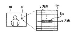
図1は、人物画像が記録媒体に形成されたプリント画像10である。
プリント画像10は、原画像の記録されたフィルムから透過型スキャナを用いて読み取られた原画像データを用いて記録媒体にプリント出力された画像、または、デジタルスチルカメラ等で撮影されて得られた原画像データを用いて記録媒体にプリント出力された画像であって、プリント画像10の画像情報を有する複数の画素を有して形成される。
ここで、原画像データは、原画像の画像情報が画素単位で表された画素単位のデータであり、例えば、640×480画素、1280×960画素等のデータサイズとなっている。このような原画像データのデータサイズは、デジタルスチルカメラによって撮影された、あるいは、透過型スキャナによって読み取られた画素単位に従って定められたものである。あるいは、コンピュータに取り込まれ、コンピュータ内で補間等によって画素数が切り替えられて作成された画像の画素単位に従って定められたものである。
また、プリント出力は、変調されたレーザ光で感光紙または感光体を露光することでプリントする方法または記録紙にインク滴を吐出させて画像をプリントする方法等で行われる。
【0021】
プリント画像10の各画素Pは、図1に示すように、領域が第1のサブ画素Sp1と第2のサブ画素Sp2とに分割されている。すなわち、プリント画像10の画素単位がn×m(n,mは自然数)のサブ画素単位に細分化され、各画素Pにはサブ画素が形成されている。
第1のサブ画素Sp1とは、被写体の画像情報を表す画素値がサブ画素値として割り当てられたものであり、第2のサブ画素Sp2とは、プリント画像10の画像情報を表す画素値のデータを符号化した情報がサブ画素値に含まれたものである。画像情報とは、プリント画像10をプリント出力する際に用いられた原画像データの画素単位の画素値の情報である。従って、第2のサブ画素Sp2には原画像データの情報が含まれている。
具体的には、第2のサブ画素Sp2に割り当てられるサブ画素値は、第1のサブ画素Sp1に割り当てられるサブ画素値に、プリント画像10の画像情報を表す画素値を符号化したものを加算したものである。
【0022】
画素値を符号化するとは、離散コサイン変換(DCT)またはカールネン・ルーベン変換(K−L変換)を用いた直交変換符号化、サブバンド符号化、ウェーブレット符号化、ベクトル量子化等公知の符号化の手法によって、画像情報を表す画素値を符号量の小さな値に変換することをいう。
【0023】
例えば、注目する画素における被写体の画像情報を表す画素値が、8ビットデータにおける126であり、画像情報を表す画素値を符号化した数値が11である場合、第2のサブ画素Sp2にはサブ画素値として137(=126+11)が割り当てられる。
また、図1に示すようにx方向に第2のサブ画素Sp2が4つ設けられる場合、各サブ画素には上述したようにそれぞれ137を与えてもよい。しかし、4つのサブ画素にn進法(nは2以上の自然数)で表した数値を順番に割り当ててもよい。例えば、画像情報を表す画素値を符号化した数値が11である場合、2進法における表示では1011であるため、図1に示す4つのサブ画素のうち最も左側のサブ画素に1を割り当て、右隣のサブ画素には0を割り当て、さらに右隣のサブ画素には1を割り当て、最も右側のサブ画素には1を割り当てるとよい。さらに、この場合、サブ画素に割り当てる値は2値化した値であればよいので、0または1の替わりに、0または1に定数を掛けて0または10としてもよい。このような定数は、サブ画素値の変化がプリント画像上で視認できないように設定する一方、反射型スキャナ等の読取装置により明確な差異を持って読み取られるように設定するとよい。この場合、第1のサブ画素Sp1と第2のサブ画素Sp2との区別が確実に行えるように、2値化される値を0以外の数値を用いるとよい。
【0024】
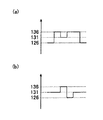
図2(a)には、上述の2値化を行って第2のサブ画素Sp2に割り当てた時の状態を示している。第1のサブ画素Sp1における画素値に126が割り当てられ、図1に示す4つのサブ画素Sp2に、左から順番に、5および10で2値化された数値10、5、10、10が、第1のサブ画素Sp1における画素値126に付加されて、136、131、136、136が割り当てられている。
【0025】
また、上述の2値化を行って第2のサブ画素Sp2にサブ画素値を割り当てる場合、図2(b)に示すように、第2のサブ画素Sp2を図1中のy方向に2段に配置し、上述の2値化した値を第1のサブ画素Sp1におけるサブ画素値に加算し、この加算結果の値を1段目の第2のサブ画素Sp2に割り当て、第1のサブ画素Sp1におけるサブ画素値から上述の2値化した値を減算し、この減算結果の値を2段目の第2のサブ画素Sp2に割り当てて、y方向に隣接する2つの第2のサブ画素Sp2同士が打ち消し合い、平均値が第1のサブ画素Sp1におけるサブ画素値となるようにするとよい。
例えば、第1のサブ画素Sp1における画素値に131が割り当てられ、第1のサブ画素Sp1におけるサブ画素値131に5加算した値136を1段目の第2のサブ画素Sp2のサブ画素値として割り当てた場合、第1のサブ画素Sp1における画素値131から5減算した値126を2段目の第2のサブ画素Sp2におけるサブ画素値として割り当てるとよい。勿論、1段目に減算結果の値を、2段目に加算結果の値を割り当ててもよい。
これにより、第2のサブ画素がプリント画像上で一層視認されにくくなる。
【0026】
なお、1つの画素内における第2のサブ画素Sp2の数は、第1のサブ画素Sp1の数に比べて圧倒的に少なく、例えば、画素が縦および横に30×30のサブ画素単位に分割されている場合、第2のサブ画素Sp2の数は多くとも数10程度であり、残りの第1のサブ画素Sp1には、被写体の画像情報を表す画素値がサブ画素値として与えられている。従って、第2のサブ画素Sp2のサブ画素値が第1のサブ画素Sp1のサブ画素値に対してある程度差異が生じても、第2のサブ画素Sp2がプリント画像上で視認されることは少ない。
また、プリント画像10の各画素は、第1のサブ画素Sp1および第2のサブ画素Sp2によって必ずしも構成される必要はなく、一部の画素は、第1のサブ画素Sp1のみで構成されてもよい。
【0027】
プリント画像10がカラー画像である場合は、シアン、マゼンタ、およびイエローの3色素による画像濃度を表した3つの画素値がそれぞれ同一の第2のサブ画素Sp2において設定されたものであってもよいし、異なる第2のサブ画素Sp2に別々に設定されたものであってもよい。
【0028】
また、プリント画像10の一部に傷が生じたり、一部が切り抜かれても、原画像データが復元できるように、プリント画像10に含まれる原画像データの情報は、複数エリアに分割して繰り返し含まれる構成としてもよい。
【0029】
このようなプリント画像10は、プリント画像10の焼き増し(再プリント)の注文が行われる場合、プリント業者に手渡されて、第1のサブ画素Sp1および第2のサブ画素Sp2のサブ画素単位で画像を読み取ることのできる高性能な反射型スキャナで読み取られる。そして、反射型スキャナで読み取った第2のサブ画素Sp2のサブ画素値と第1のサブ画素Sp1のサブ画素値との差分が求められ、この差分から原画像データが復元される。従って、プリント画像10の画像情報を有する第1のサブ画素Sp1のサブ画素値の読取データを用いることなく、正確な原画像データをプリント画像10から取得することができる。
勿論、プリント画像10をプリント出力する際に行った画像処理の情報が、原画像データの他に第2のサブ画素Sp2に含まれている場合、原画像データの取得と同時に画像処理の情報を取得し、取得された画像処理の情報を用いて原画像データに画像処理を施して、プリント画像10の再現プリントをプリント出力することができる。
【0030】
上記例のプリント画像10では、第2のサブ画素Sp2に割り当てられるサブ画素値は、プリント画像10の原画像データを符号化した数値を、第1のサブ画素Sp1に割り当てられるサブ画素値に加算した値であるが、本発明においてはこの加算の替わりに減算した値を、第2のサブ画素Sp2に割り当ててもよい。
また、第2のサブ画素に割り当てるサブ画素値は、プリント画像10の画像情報を表した画素値に関する情報が含まれたものであるが、本発明では、画像の再プリントを行う際に用いる再プリント用データの値が含まれたものであればどのようなものであってもよい。
例えば、原画像の画像情報を表した原画像データの他に、プリント画像の再プリントを注文した顧客識別情報が含まれてもよいし、原画像データを用いてプリント画像10をプリント出力する際に原画像データに施した画像処理の情報が含まれてもよい。また、原画像データの他に、プリント画像10内の被写体に関する情報が含まれてもよい。被写体に関する情報とは、例えば、GPS(Global Positioning System)機能付カメラで撮影した時の撮影位置情報を用いて撮影被写体を3次元地図情報等から同定した情報、例えば、「富士山」、「山中湖」等の情報である。このような情報は、勿論符号化されて含まれるとよい。
【0031】
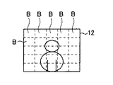
また、図3に示すように、プリント画像12は、互いに隣接する複数の画素によって形成された複数のブロック領域Bを有し、各ブロック領域Bの範囲の原画像データの平均値に関する情報が、それぞれのブロック領域Bに位置する第2のサブ画素Sp2に含まれるものであってもよい。この場合、ブロック領域B毎の平均値を符号化したものが、第1のサブ画素Sp1のサブ画素値に加算されて、第2のサブ画素Sp2におけるサブ画素値として割り当てられるとよい。
【0032】
プリント画像12の焼き増し(再プリント)の注文が行われる場合、プリント画像12は業者に手渡されて、第1のサブ画素Sp1および第2のサブ画素Sp2のサブ画素単位で画像を読み取ることのできる高性能な反射型スキャナで読み取られる。そして、反射型スキャナで読み取った第2のサブ画素Sp2のサブ画素値と第1のサブ画素Sp1のサブ画素値との差分が求められ、この差分からブロックB毎の原画像データの平均値が復元される。
従って、反射型スキャナで読み取った第1のサブ画素Sp1のサブ画素値からなる読取データを、各ブロックB毎の原画像データの平均値になるようにブロック領域B毎に調整し、原画像と略同等の画像濃度を持つプリント画像12の再現画像をプリント出力することができる。
すなわち、画像濃度を調整するための画像濃度調整用データを、第2の画素Sp2におけるサブ画素値に含ませ、再プリントの際に画像濃度の調整用データとして用いることができる。
【0033】
また、第2のサブ画素Sp2は、ブロック領域B毎の画素値の平均値の情報を含む替わりに、原画像におけるブロック領域B毎の鮮鋭度を表す情報を含むものであってもよい。
ブロック領域B毎の鮮鋭度を表す情報とは、所定の微分フィルタを用いてシャープネス強調を行った場合における画素値の情報である。
第2のサブ画素Sp2のサブ画素値に含まれる原画像の鮮鋭度を表す情報は、高性能な反射型スキャナでサブ画素単位で第1のサブ画素Sp1のサブ画素値と第2のサブ画素Sp2のサブ画素値とを読み取ることによって取得できる。この鮮鋭度を表す情報を用いて、第1のサブ画素Sp1のサブ画素値からなる読取データをブロック領域B毎に調整し、原画像と略同等の鮮鋭度を持つプリント画像12の再現画像をプリント出力することができる。
すなわち、画像の鮮鋭度を調整するための鮮鋭度調整用データを、第2の画素Sp2におけるサブ画素値に含ませ、再プリントの際に鮮鋭度の調整用データとして用いることができる。
【0034】
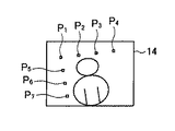
また、図4に示すように、プリント画像14は、プリント画像14を形成する複数の画素のうち、プリント画像上の予め定められた位置に本来あるべき基準画素に対して第1の画素Sp1と第2の画素Sp2とが形成されてもよい。
第1のサブ画素Sp1には、プリント画像14の各画素における画素値がサブ画素値として割り当てられ、第2のサブ画素Sp2には、予め定められたサブ画素値、あるいは、予め定められた値を第1のサブ画素Sp1のサブ画素値に加算した値がサブ画素値として割り当てられる。
例えば、第1のサブ画素Sp1と第2のサブ画素Sp2とで構成される基準画素の本来あるべき画素位置は、プリント画像14における左上の角を原点として右方向、下方向を正方向にとった2次元座標系において、位置P1 (50,50),位置P2 (100,50),位置P3 (150,50),位置P4 (200,50), 位置P5 (50,100),位置P6 (50,150),位置P7 (50,200)とする。このような位置P1 〜P7 におけるプリント画像14上の画素位置を知ることによって、プリント画像14自体の幾何歪みまたは反射型スキャナで読み取った時の画像の傾斜を求めることができ、この情報を用いて、プリント画像14の再プリントの際に各画素の位置調整を行うことができる。
すなわち、第1のサブ画素Sp1と第2のサブ画素Sp2とで構成された画素のプリント14上の位置情報を画素位置調整用データとして用いることができる。図4に示す例では、位置P1 〜P7 の画素位置が本来あるべき画素位置からずれて、プリント画像14が傾斜している状態を示している。
なお、このような基準画素の本来あるべき画素位置の情報を符号化し、再プリント用データとして第2のサブ画素Sp2のサブ画素値に割り当ててもよい。
【0035】
このようなプリント画像は以下のようにして作成される。
以下、プリント画像10を作成する方法を例として、本発明のプリント画像の作成方法を説明する。
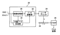
図5は、プリント画像10をプリント出力するシステムであって、画像処理装置20およびレーザプリンタ24およびプロセサ26を有する。なお、レーザプリンタ24は、DSCまたは透過型スキャナ等で取得される原画像データの画素数に比べて大きな画素数でプリント画像を露光記録することができる高性能なプリンタである。
【0036】
画像処理装置20は、画像処理部28、付属データ生成部30およびデータ調整部32を主に有して構成される。勿論、画像処理装置20にマウスまたはキーボード等の図示されない操作系および図示されないモニタが接続され、モニタに表示された入力設定画面を見ながら、操作系で画像処理または付属データについての指示を行うことができる。
【0037】
画像処理部28は、DSCまたは透過型スキャナ等から供給された原画像データに対して、プリント画像が適切な画像となるように、供給された原画像データに基づいて自動的に設定された画像処理条件または操作系を用いて指示入力された画像処理条件に基づいて画像処理を行う部位である。例えば、色/濃度補正、中間階調を保持したダイナミックレンジの圧縮/伸長(画像処理による覆い焼き効果の付与)、電子変倍処理(画像の拡大/縮小)、鮮鋭化処理(シャープネス)、さらに、必要に応じて、各画素の位置調整、空間周波数におけるフィルタリング処理、微分処理または画素位置の再配置処理等の所定の画像処理が行われる。
【0038】
付属データ生成部30は、画像処理部28から供給された画像処理後の原画像データ自体を符号化する部位である。符号化は、上述した公知の符号化の手法によって行われる。
符号化された原画像データは、付属データとしてデータ調整部32に供給される。
【0039】
データ調整部32は、画像処理部28から供給された、原画像の画像情報が画素値で表された画素単位の原画像データから、画像処理部28から供給された原画像データの値をサブ画素値としてサブ画素に割り当てた第1のサブ画素Sp1と、付属データ生成部30から供給された原画像データの符号化された値を、上記第1のサブ画素Sp1に割り当てられたサブ画素値に加算した値をサブ画素に割り当てた第2のサブ画素Sp2とを有するサブ画素単位のデータを生成する部位である。
なお、ここでいうサブ画素とは、レーザプリンタ24で記録可能な画素に対応する。すなわち、レーザプリンタ24は、DSCまたは透過型スキャナで読み取られる原画像の画素に比べて細かな画素(サブ画素)で露光記録することができる。
こうして生成されたサブ画素単位のデータはレーザプリンタ24に送られる。
【0040】
レーザプリンタ24は、供給されたサブ画素単位のデータを用いてレーザビームLのオン、オフを制御する変調信号を生成し、感光紙34にサブ画素単位の潜像を露光記録するプリンタであり、上述したように、DSCまたは透過型スキャナ等で取得される原画像データの画素数に比べて大きな画素数で露光記録する高性能なプリンタである。プリンタは、変調されたレーザ光で感光紙または感光体を露光することでプリントするレーザプリンタの他、記録紙にインク滴を吐出させて画像をプリントするインクジェットプリンタ等であってもよい。
レーザプリンタ24で露光記録された感光紙34は、プロセサ(現像処理装置)26に供給されて顕像化され、プリント画像10が出力される。
【0041】
なお、第2のサブ画素Sp2に画像処理後の原画像データの情報を含ませる替わりに、画像処理前の原画像データの情報を含ませてもよい。この場合、画像処理部28において原画像データに施した画像処理の情報を、第2のサブ画素Sp2に含ませるのがよい。
【0042】
このように、プリント画像10に原画像データを含ませているので、原画像または原画像データを別途保管する必要がなくなる。このため、再プリントの注文時に、例えば、原画像が撮影されたフィルムまたは原画像データを業者に受け渡す必要がなくなり、画像処理装置等に保管されている原画像データまたは画像処理の情報を検索する必要がなくなる。また、プリントの画像領域以外に原画像データまたは画像処理の情報を記録格納する領域を別途設ける必要もない。従って、プリント画像を読み取る場合、画像領域のみを読み取ればよい。
【0043】
上記例は、プリント画像10を生成する例であるが、本発明ではプリント画像12、14を作成することもできる。
プリント画像12を作成する場合、まず、付属データ生成部30は、DSCや透過型スキャナから原画像データの供給を受ける。付属データ生成部30では、予め設定された画像上のブロック領域B毎の原画像データの平均値が求められ、この平均値のデータを符号化して付属データが生成される。この付属データはデータ調整部32に供給される。また、ブロック領域B毎の原画像データの平均値の替わりに、ブロック領域B毎の原画像の鮮鋭度を求めて符号化してもよい。
あるいは、画像上の予め定められた位置にあるべき基準画素に対応する、画像処理後の画素単位で表された原画像データに、第2のサブ画素値を割り当てるように付属データを生成してもよい。
【0044】
なお、データ調整部32では、作成されるプリント画像10、12、14において、第2のサブ画素Sp2が視認されにくく、かつ、原画像を再現する際に反射型スキャナで読み取り易いように、反射型スキャナの第2のサブ画素Sp2の読取データの値と第1のサブ画素Sp1のサブ画素の読取データの値との差が大きく、かつ、第2のサブ画素Sp2と第1のサブ画素Sp1との色差が小さくなるように、第1のサブ画素Sp1のサブ画素値に応じて、付属データに変換処理を施してもよい。
一般に、プリント画像における低濃度部分(明るい部分)では人間の弁別性(人間が視認することのできる色差の特性)は高く、高濃度部分(暗い部分)では人間の弁別性は低い。従って、この人間の弁別姓を利用して、第1のサブ画素Sp1のサブ画素値に応じて、付属データに変換処理を施すことで、第2のサブ画素Sp2が視認されにくく、かつ、原画像を再現する際に反射型スキャナで原画像を読み取り易くすることができる。
【0045】
例えば、プリント画像10の作成において、第1のサブ画素Sp1が低濃度部分に対応するサブ画素値を有する場合、符号化された原画像データの値を小さくするように変換処理し、一方、第1のサブ画素Sp1が高濃度部分に対応するサブ画素値を有する場合、符号化された原画像データの値を大きくするように変換処理し、この変換処理した結果に第1のサブ画素Sp1のサブ画素値を加算し第2のサブ画素Sp2のサブ画素値に割り当てる、変換処理方式を行うとよい。
【0046】
図2(a)に示す例では、符号化された原画像データの値が5と10であるが、上記変換処理を行うことによって、低濃度部分では例えば2と4、高濃度部分では例えば10と20のように、加算すべき値を、第1のサブ画素Sp1のサブ画素値に応じて調整する変換処理を行う。
この変換処理は、予め人間の弁別性の特性を実験的に求めて作成された変換テーブルを記憶保持しておき、この変換テーブルを用いて行われるとよい。こうしてデータ調整部32では、変換処理後の、符号化された原画像データを用いて、サブ画素単位のデータが生成される。
【0047】
あるいは、人間の弁別性を利用し、所定以上の濃度(中濃度または高濃度)を有する領域を自動的に選択し、この領域に第2のサブ画素Sp2を形成し、第1のサブ画素Sp1のサブ画素値を付属データの値に加算して第2のサブ画素Sp2のサブ画素値に割り当てる、領域選択方式を行ってもよい。この場合、上述の変換処理を併用してもよい。
上記変換処理方式または上記領域選択方式は、赤(R)信号データ、緑(G)信号データおよび青(B)信号データの3信号データのそれぞれに対して別々に、しかも、別々の変換処理または領域選択を行うのが好ましい。
【0048】
次に、プリント画像10、12、14を読み取り、原画像を再現したプリント画像の再現方法を説明する。
プリント画像10は、第1のサブ画素Sp1および第2のサブ画素Sp2のサブ画素単位で読み取り可能な高性能な反射型スキャナを用いて読み取られて、読取データが取得され、画像処理装置28に供給される。
画像処理装置28では、空間周波数におけるフィルタリング処理および微分処理が行われて、第2のサブ画素Sp2に割り当てられたサブ画素値が取り出されるとともに、第1のサブ画素SP1に割り当てられたサブ画素値が取り出されて、第2のサブ画素Sp2におけるサブ画素値と第1のサブ画素SP1におけるサブ画素値の差分が求められ、この差分のデータに復号化処理が施されて、再プリント用データである原画像データが復元される。
【0049】
この復元された原画像データは、付属データ生成部30に供給され、この付属データ生成部30において、供給された原画像データが上述したように符号化されて、付属データとしてデータ調整部32に送られる。一方、データ調整部32には、画像処理部28から原画像データが供給されるので、データ調整部32では上述したサブ画素単位のデータが生成され、レーザプリンタ24に供給される。
こうして、反射型スキャナで読み取られた読取データを直接用いず、読取データに含まれている第2のサブ画素SP2に割り当てられたサブ画素の値から原画像データを復元してプリント画像10を再現したプリント画像を出力する。
【0050】
一方、プリント画像12を反射型スキャナで読み取った場合には、画像処理部28で空間周波数におけるフィルタリング処理および微分処理が行われて、第2のサブ画素Sp2に割り当てられたサブ画素値が取り出されるとともに、第1のサブ画素SP1に割り当てられたサブ画素値が取り出されて、第2のサブ画素Sp2におけるサブ画素値と第1のサブ画素SP1におけるサブ画素値の差分が求められ、この差分のデータに復号化処理が施され、ブロック領域B毎の原画像データの平均値(画像濃度の平均値)が取得される。
【0051】
画像処理部28では、さらに、取得されたブロック領域B毎の平均値に基づいて、反射型スキャナで読み取られた第1のサブ画素Sp1におけるサブ画素値からなる読取データに対してブロック領域B毎の画像濃度の調整が行われる。
画像濃度の平均値の替わりに鮮鋭度の情報が第2のサブ画素Sp2におけるサブ画素値に割り当てられている場合も同様に、復元された鮮鋭度のデータに基づいて、反射型スキャナで読み取られた第1のサブ画素Sp1におけるサブ画素値からなる読取データに対して鮮鋭化処理が行われる。
勿論、これらの処理は、赤(R)信号データ、緑(G)信号データおよび青(B)信号データの3信号データのそれぞれに対して行うのが好ましい。
画像処理の行われた読取データは、データ調整部32に供給され、一方、画像処理部28で取得された原画像データのブロック領域B毎の平均値あるいは鮮鋭度が付属データ生成部30を介してデータ調整部32に供給され、データ調整部32においてサブ画素単位のデータが生成される。こうして調整されたサブ画素単位のデータは、レーザプリンタ24に供給され、プリント出力のために用いられる。
【0052】
このように、プリント画像12の場合は、上述したプリント画像10の場合と異なり、反射型スキャナで読み取られた読取データに画像濃度調整または鮮鋭化処理の画像処理が施されてプリント出力のために用いられる。その際、第2のサブ画素Sp2に含まれた原画像データのブロック領域B毎の平均値あるいは鮮鋭度が用いられて画像処理が行われる。
このように、画像濃度調整用データまたは鮮鋭度調整用データをプリント画像12に含ませる場合、原画像データを含ませる場合に比べて少ないデータ量で済み、レーザプリンタ24または反射型スキャナの記録精度または読取精度に起因するプリント画像の画像濃度、色味、濃度むらを補正することができ、また、鮮鋭度劣化を抑制することができる。
【0053】
一方、プリント画像14を反射型スキャナで読み取った場合には、画像処理部28で空間周波数におけるフィルタリング処理および微分処理が行われて、第2のサブ画素Sp2に割り当てられたサブ画素値が取り出されるとともに、第1のサブ画素SP1に割り当てられたサブ画素値が取り出される。そして、第2のサブ画素Sp2が形成されている基準画素のプリント画像14上の画素位置が取得される。
基準画素は、予め画素位置が定められたものであるため、取得されたプリント画像14上の基準画素の画素位置と予め定められた本来あるべき画素位置とのずれ量を求め、このずれ量から、読み取られた画像の幾何歪みまたは傾斜の情報を求めることができる。
【0054】
画像処理部28は、読み取られた画像の幾何歪みまたは傾斜の情報を求め、この情報を用いて、反射型スキャナで読み取られた第1のサブ画素Sp1におけるサブ画素値からなる読取データに対して画像位置の再配置処理が行われ、幾何歪みのない、また、傾斜が調整された画像を表す画像処理後のデータが生成され、データ調整部32に供給される。
画像処理部28で取得された基準画素であることを示す第2のサブ画素Sp2に含ませるデータが付属データ生成部30を介してデータ調整部32に供給され、データ調整部32においてサブ画素単位のデータが生成される。こうして調整されたサブ画素単位のデータは、レーザプリンタ24に供給され、プリント出力のために用いられる。
【0055】
プリント画像14の場合、上述したプリント画像12の場合と同様に、反射型スキャナで読み取られた読取データに画素位置調整のための画像処理が施された後プリント出力のために用いられる。
このようにプリント画像14に基準画素を含ませるので、プリント画像14をレーザプリンタ24を用いてプリント出力する際の記録精度または反射型スキャナでプリント画像14を読み取る際の読取精度に起因する画像の幾何歪み、あるいは、反射型スキャナでプリント画像14を読み取る際のプリント画像の位置ずれ、さらには、感光紙34等の記録媒体の変形または皺に起因する幾何歪みを補正することができる。
【0056】
上述したように、プリント画像10、12が、付属データに対して上記変換処理あるいは上記領域選択が行われてプリント出力された場合、画像処理部28において、上記変換処理の逆変換処理を行う、また、領域選択された領域を自動的に抽出する構成とし、少なくとも付属データを抽出する処理を画像処理部28において施す。
【0057】
以上のように、本発明の第1の態様では、プリント画像を構成する画素中に、画像を表示するための第1のサブ画素と、画像を再プリントする際に用いる再プリント用データを記録するための第2のサブ画素を設けることによって、視認されるプリント画像と視認不可能な再プリント用データとを1つのプリントに記録している。これにより、原画像を記録したフィルムや原画像データ、画像処理の情報を別途保管することなく、このプリントのみから同様のプリントを再現することが可能となる。
【0058】
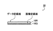
次に、本発明の第2の態様として、画像を記録したプリントの表面に無色透明のデータ記録層を設け、このデータ記録層に再プリント用データを視認不可能な形態で記録したプリントの作成方法およびこれにより作成されるプリントについて説明する。本態様のプリント作成方法によって得られた本発明のプリントを図6に示す。図6は、プリント16の模式的断面図である。
【0059】
プリント16は、図6に示すように、画像を記録する記録媒体である感光紙16Qと、感光紙16Qの画像記録面に貼着された、再プリント用データ記録層としての透明なプラスチック層16Rを有する。プラスチック層16Rの表面には、所定の深さおよび開口面積を有する微細な凹部が所定の間隔で形成されることにより、再プリント用データが記録されている。
【0060】
感光紙16Qは、通常のプリントに用いられるカラー用またはモノクロ用の感光紙(印画紙)である。なお、本実施例においては、感光材料である感光紙16Qを露光することで画像を記録するフォトプリンタにより画像の記録を行うが、感光紙16Qに代えて普通紙や感光感熱材料、感光感圧材料等を用い、インクジェットプリンタや電子写真プリンタ、サーマルプリンタ等によって画像を記録してもよい。
【0061】
プラスチック層16Rとしては、感光紙16Qに記録された画像の観察を妨げず、且つ凹部が形成可能であれば、各種の材料が利用可能であり、例えば、各種のポリマーフィルムや、アクリル系樹脂、ポリエチレン、ポリ塩化ビニル等各種のプラスチックフィルム等が好適に利用される。また、プラスチック層16Rの厚さには限定は無いが、感光紙16Qの画像の観察への影響を最小限にし、かつプラスチック層16Rへの凹部形成を可能とする範囲に設定する。
【0062】
プラスチック層16Rに記録される再プリント用データとしては、本発明の第1の態様において第2のサブ画素で表現されるデータと同様のものが例示される。すなわち、画像処理後または画像処理前の原画像データ、原画像データに施した画像処理の情報、顧客識別情報や原画像中の被写体に関する情報等が記録可能である。これらの再プリント用データのうち、好ましくは原画像データを含む1つ以上が、公知の手法によって2値情報に符号化され、予め設定された深さおよび開口面積の凹部が、プラスチック層16Rの表面の、前記2値情報に応じた位置に形成される。これにより、原画像データ等の再プリント用データが、凹部の有無によって表現される2値データとしてプラスチック層16Rに記録される。ここで、前記凹部の深さはプラスチック層16Rの厚さよりも小さく、開口面積は感光紙16Qに記録された画像の原画像データの画素よりも十分小さい。
【0063】
プラスチック層16Rに凹部を形成することによる再プリント用データの記録形態には、特に制限は無く、例えば、感光紙16Qに記録された画像の1画素に対応するプラスチック層16Rの領域に、その画素の原画像データであるR,G,Bの各画像信号データを記録し、同領域内の残りのスペースに画像処理の情報等を記録してもよいし、感光紙16Qの画像の画素位置に関係無く、プラスチック層16Rに、予め定めた配列形態に則って、原画像データおよびその他の再プリント用データを記録してもよい。また、再プリント用データを公知の手法により圧縮して記録してもよい。原画像データの圧縮を行うことでデータ量が小さくなるため、より多くの画像処理関連データ等を記録することもできる。
【0064】
感光紙16Qが複数の画像を記録した、いわゆるインデックスプリントである場合には、プラスチック層16Rにそれら複数の画像の再プリント用データを記録する。また、感光紙16Qに記録された1つの画像に対し、関連する複数の画像(同じフィルムに撮影された画像、同日に撮影された画像等)の再プリント用データをプラスチック層16Rに記録してもよい。
【0065】
プラスチック層16Rは、感光紙16Qに貼着される薄さにおいて無色透明であり、再プリント用データは超微細な凹部によって記録されているので、プラスチック層16Rが感光紙16Qに記録された画像の見え方に影響を及ぼすことは無く、プラスチック層16Rに記録された再プリント用データも視認不可能である。また、上述のようにプラスチック層16Rを感光紙16Qの画像記録面に貼着することで、感光紙16Qに記録された画像の保護膜としても機能する。
【0066】
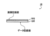
なお、図7に示すように、プラスチック層18Rを感光紙18Qの非画像記録面(非感材面)に設けてもよく、この際には、プラスチック層18Rを着色された層で構成してもよい。着色層の場合には、再プリント用データが可視的に記録される形態としてもよいし、凹部の形成により文字や記号、絵柄等を表示することも可能であり、プリント18のバックプリントをこの方法により行ってもよい。
さらに、上記の2つの方法を組み合わせ、データ記録層としてのプラスチック層を感光紙の画像記録面および非画像記録面の両方に設けてもよい。
【0067】
再プリント用データを担持する凹部の形成方法は、目的とするサイズおよび密度で凹部を形成可能なものであれば特に限定は無く、マイクロマシン技術による方法やアブレーション等を利用して光学的に記録する方法等、各種の方法が利用可能である。好ましい1例としては、IBM(International Business Machines Corporation )により開発されている新記憶媒体技術「ミリピード(Millipede )」が例示される。これは、パンチカードの原理を利用した記録方法で、アームの先端に設けられたナノスケールの超微細な先端部を、高温の状態でポリマー薄膜に接触させて直径10nm程度の超微細な穴を開けることで、6.45cm2 当たり1兆ビット(1テラビット)のデータが記録可能とされている。この方法等によって、超微細先端を有する高温の部材を、プラスチック層16Rの表面の所定の位置に接触させ所定の深さまで到達させることにより、溶融部材の接触部近傍のプラスチックを熱変形させ、所定の形状の凹部を形成する。凹部を形成したプラスチックは、その状態で冷却されて固化することにより凹部形状が安定的に維持され、データが保持される。
【0068】
このようなプリントは以下のようにして作成される。
以下、プリント16を作成する方法を例として、本発明のプリントの作成方法を説明する。
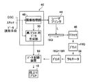
図8は、プリント16を出力するシステムであって、画像処理装置40、レーザプリンタ44、プロセサ46、ラミネータ56およびデータ記録装置58を有する。
【0069】
画像処理装置40は、画像処理部48および再プリント用データ生成部50を主に有して構成される。画像処理装置40には、マウスまたはキーボード等の図示されない操作系および図示されないモニタが接続され、モニタに表示された入力設定画面を見ながら、操作系で画像処理または再プリント用データについての指示を行うことができる。
画像処理部48および再プリント用データ生成部50は、図5の画像処理装置20における画像処理部28および付属データ生成部30と基本的に同様の構成および作用を有する。画像処理部48は、DSCまたは透過型スキャナ等から供給された原画像データに対して所定の画像処理を施して再プリント用データ生成部50およびレーザプリンタ44に供給する。再プリント用データ生成部50は、画像処理部48から供給された画像処理後の原画像データを上述の手法により符号化して2値データとし、データ記録装置58に供給する。
【0070】
レーザプリンタ44は、図5のレーザプリンタ24と同様のプリンタであり、供給された処理後の原画像データに応じてレーザビームLを変調して、感光紙16Qに潜像を露光記録する。なお、本実施例においては、レーザプリンタ44はサブ画素単位での記録は行わないので、通常の性能を有するプリンタであればよい。
プロセサ46は、レーザプリンタ44から供給された感光紙16Qに現像処理を施し、感光紙16Qの潜像を顕像化して出力する。
【0071】
ラミネータ56は、プロセサ46から出力された感光紙16Qの画像記録面にフィルム状のプラスチック層16Rをラミネートする。ラミネータ56によるプラスチック層16Rのラミネートは、公知のラミネート技術を用いて行えばよく、プラスチック層16Rが感光紙16Qに密着するに十分な温度および圧力等の条件下で行われる。プラスチック層16Rがラミネートされた感光紙16Q(プリント16)はデータ記録装置58に送られる。
なお、ラミネータ56を、塗膜装置とし、公知の塗膜技術等により、プラスチックが溶融した状態で感光紙16Qに塗布して乾燥させることによりプラスチック層16Rを形成してもよい。
【0072】
データ記録装置58は、再プリント用データ生成部50から供給された原画像データが符号化された値を記録用の信号に変換し、この信号に応じてプリント16のプラスチック層16Rに、所定の深さおよび開口面積の凹部を形成することにより、符号化された原画像データを記録する。この記録方法は前述の通りである。
【0073】
以上により、感光紙16Qに画像が記録され、プラスチック層16Rに再プリント用データとして符号化された原画像データが記録されたプリント16が、仕上がりプリントとしてデータ記録装置58から出力される。
このように、プリント16に原画像データが記録されているので、原画像または原画像データを別途保管する必要がなくなる。このため、再プリントの注文時に、例えば、原画像が撮影されたフィルムまたは原画像データを業者に受け渡す必要がなくなり、画像処理装置等に保管されている原画像データまたは画像処理の情報を検索する必要がなくなる。また、原画像データは画像記録層とは異なる層に高密度で記録されるので、データ記録領域の確保のためにプリント面積を増大する必要もない。
【0074】
なお、感光紙18Qの非感材面にプラスチック層18Rが設けられたプリント18を作成する場合には、ラミネータ56において感光紙18Qの非感材面にプラスチック層18Rを貼着し、データ記録装置58において、このプラスチック層18Rにデータ記録を行えばよい。
あるいは、感光紙18Qの製造時に、プラスチック層18Rを感光紙18Qのベースとして構成し、プラスチック層18Rの上に感光材料(乳剤)を塗布して、非感材面がプラスチック層18Rである感光紙18Qを作製してもよい。このような感光紙18Qを用いてプリント18を作成する場合には、図8に示すプリント作成システムにおいて、ラミネータ56の無い形態とし、画像が記録されてプロセサ46から出力された感光紙18Qを、データ記録装置58に供給して、データ記録装置58において符号化された原画像データを記録すればよい。
また、プラスチック層18Rが非感材面に設けられる場合は、プラスチック層18Rへの凹部形成によるデータ記録は、感光紙18Qへの画像の記録よりも先に行ってもよい。
【0075】
次に、このようにして作成されたプリント16(18)のプラスチック層16R(18R)からデータを読み取り、プリント16の再プリントを行う方法について、プリント16を例に説明する。
プリント16の原画像データは、図8のプリント作成システムのデータ読取手段(図示省略)が、プラスチック層16Rを読み取ることにより得られる。データ読取手段としては、各種の手段が利用可能であり、光学的読取手段や、上述したIBMのミリピードの技術等を用いた方法、すなわち、記録時よりも低く、プラスチック層16Rの凹部を変形させない温度の微細先端部でプラスチック層16R表面をスキャンすることにより、プラスチック層16Rの読み取りを行う方法が例示される。
データ読取手段は、得られた原画像の符号化データを復号化し原画像データとして画像処理部48に供給すると共に、符号化データをそのまま再プリント用データ生成部50に供給する。
【0076】
本例では、プラスチック層16Rに画像処理後の原画像データが記録されているので、画像処理部48は、供給された原画像データに必要な処理のみを施してレーザプリンタ44に供給する。再プリント用データ生成部50は、データ読取手段から供給された原画像の符号化データをデータ記録装置58に供給する。
以下、前述のプリント16の作成処理と同様の処理を行って、再プリント16が作成される。
【0077】
なお、再プリント時に、画像処理部48において原画像データに画像処理を施す場合も有る。この場合には、この画像処理後の原画像データを画像処理部48から再プリント用データ生成部50に供給し、再プリント用データ生成部50で符号化して、データ記録装置58に供給してもよい。
【0078】
以上、プラスチック層16Rに画像処理後の原画像データを記録する場合のプリント16の作成方法、およびプリント16の再現方法(再プリント方法)を説明したが、上述したように、再プリント用データ生成部50で生成され、データ記録装置58でプラスチック層16Rに記録される再プリント用データは、画像処理後の原画像データに限らず、画像処理前の原画像データでもよい。この場合、画像処理部48において原画像データに施した画像処理の情報も合わせて記録するのが好ましい。原画像データ以外にも、上述した各種の再プリント用のデータ等が記録可能である。
【0079】
プラスチック層16Rに原画像データが記録されておらず、画像処理の情報等が記録されていた場合の再プリント時には、反射型スキャナを用いて感光紙16Qに記録された画像が読み取られ、原画像データとして画像処理部48に供給される。ここで、プリント16の場合には、画像記録面上に設けられているプラスチック層16Rが、反射型スキャナでの読取画像データに影響を及ぼし、適正な原画像データが得られない可能性がある。このような影響を無くすため、プラスチック層16Rの反射率等の特性から予め補正データを作成しておき、これにより読取画像データを補正して原画像データとするのも好ましい。このようにして得られた原画像データに対し、プラスチック層16Rに記録されている画像処理の情報等に従って画像処理を施すことにより、元のプリント画像と同画質のプリントを再現することができる。
【0080】
ところで、プラスチック層16R(18R)に記録するデータは、上記の再プリント用データ以外にも、動画データや音声データ等の、感光紙16Q(18Q)の画像を鑑賞する際に再生される関連データ等が記録可能である。以下プリント16を例に説明する。
プラスチック層16Rに動画データを符号化して記録する場合には、感光紙16Qにその代表コマをプリントして静止画の鑑賞用とする。動画の再生は、上述のデータ読取手段および動画を表示するディスプレイまたはプロジェクタ等を有する再生装置にプリント16をセットすることにより行われる。
また、プラスチック層16Rに音声データを記録する場合には、音声を符号化してプリント16のプラスチック層16Rに記録する。プリント16が、上記データ読取手段および音声を出力するスピーカ等を備える再生装置によって再生されることにより、記録された音声を聞きながらプリント16に記録された画像を鑑賞できる。プリント16の再プリント時に、プラスチック層16Rに記録された音声データを文字化して、文字データを画像データに合成して感光紙16Qに記録する形態としてもよい。
【0081】
なお、本実施例においては、再プリント用データをプリントに貼着したデータ記録層に記録しているが、プリントの収納ケースにデータ記録層を設けることも可能である。すなわち、撮影日や撮影単位(1回の旅行分、フィルム1本分等)等で分類される複数のプリントをまとめて収納する収納ケースを、データ記録用のプラスチックで製造し、この収納ケースに収納されるプリントの再プリント用データを、上述の例と同様にして、この収納ケースに記録してもよい。あるいはプリントの収納ケースにデータ記録用のプラスチックフィルムを貼着し、同様の記録を行うようにしてもよい。
これにより、フィルムや画像データを保管することなく、この収納ケースに収納されているプリントと同様のプリントを再現できる。また、同一のケースに収納されるプリントの何枚かが紛失したり損傷した場合にも、残っているプリントから、再プリント用データが記録されているケースが一目で分かり、プリントを再現することができる。
【0082】
以上説明したように、本発明の第2の態様では、プリントに、画像を記録する層と、再プリント用データを記録する無色透明のプラスチック層とを設けて、視認されるプリント画像と視認不可能な再プリント用データとを1つのプリントに記録している。これにより、原画像を記録したフィルムや原画像データ、画像処理の情報を別途保管することなく、このプリントのみから同様のプリントを再現することが可能となる。
【0083】
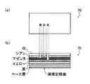
次に、本発明の第3の態様として、プリントの非画像記録面(非感材面)に多色のプラスチック層から成るデータ記録層を形成し、このプラスチック層に所定の深さおよび開口面積の凹部を所定の位置に形成することにより、再プリント用データを記録するプリント作成方法、およびこれにより作成されるプリントについて説明する。本態様のプリント作成方法によって得られた本発明のプリントを図9に示す。図9は、プリント70を模式的に示す図であり、(a)は上面図(非感材面、裏面)、(b)は断面図である。
【0084】
プリント70のデータ記録層は、図9に模式的に示すように、互いに異なる色の不透明な薄いプラスチック層を重ね合わせて成る。各プラスチック層には、上述の例におけるデータ記録用のプラスチックと同様の各種のプラスチック材料が利用される。本実施例においては、ベース層の上に、黒のプラスチック層、シアン、マゼンタおよびイエローの各色のプラスチック層、および白のプラスチック層が積層されている。このプラスチック層の色および数には特に限定は無く、記録するデータ量や記録形態等に応じて適宜設定されればよい。
【0085】
このようなプリント70のデータ記録層には、各プラスチック層に達する所定の深さおよび開口面積の凹部を、記録するデータに応じた位置に形成することにより、その深さに応じたプラスチック層の色が、面積に応じた量だけ露出し、この凹部(ドット)が多数形成されることにより可視像が記録される。プリント70への凹部の形成は、本発明の第2の態様におけるデータ記録方法と基本的に同様の方法により行うことができる。
【0086】
このように、複数色のプラスチック層からなるプリント70に、深さの異なる凹部を形成してデータを記録することで、より多くの再プリント用データを記録することができる。また、このようにして記録された再プリント用データは、上述した各種の読取手段によって凹部の有無を読み取るほか、色味でデジタル信号を読み取ることもできる。
【0087】
さらに、この方法では、各層のプラスチック色を露出させることにより、単位面積あたりの各色のドット密度で階調を表現することができるため、例えばインクジェット記録方式のように、各色毎に面積変調を行うように凹部を形成することにより、文字や画像等の視覚的情報や可視像を記録することも可能である。この方法によれば、文字や画像等を記録するためのインク等も不要となる。
【0088】
以上説明したように、本発明の第3の態様でも、1つのプリントにプリント画像と再プリント用データを記録することが出来る。そのため、原画像を記録したフィルムや原画像データ、画像処理の情報を別途保管することなく、このプリントのみから同様のプリントを再現することが可能となる。
【0089】
上記では、データ記録層としてのプラスチック層を非画像記録面に設け、再プリント用データを記録しているが、本発明のさらに別の態様では、このような多色のプラスチック層側の面を画像記録面とすることも可能である。
すなわち、図9のプリント70を、感光材料等の画像記録層を有さず、ベース層および互いに色の異なる多層のプラスチック層で構成し、多層のプラスチック層を画像記録層として、ここに、画像データに応じて、各色の層に達する所定の深さの凹部を所定位置に形成することで画像(可視像)を記録する。
【0090】
画像記録層としてのプラスチック層が、図9の例と同様に、ベース層の上に、黒、シアン、マゼンタ、イエローおよび白の各色のプラスチック層を積層したものであれば、カラー画像を記録できる。また、さらに層を増やして色数を多くしてもよいし、モノクロ画像を記録するのであれば、プラスチック層は例えば白黒の2層でもよい。また、ベース層を画像記録層として利用してもよい。積層する色の順は適宜設定されればよい。
【0091】
なお、このような画像記録層あるいはデータ記録層となる多色層は、上述のプラスチック材料には限定されず、所定の色を有し、所定の深さおよび開口面積の凹部を形成可能であり、かつ、形成された凹部形状を維持するものであればどのような材料を用いてもよく、例えば固形インクや顔料を含んだワックス等も利用可能である。
【0092】
また、凹部形成により画像を記録するプリントの一方または両方の面にデータ記録層を設け、再プリント用データを記録するのも好ましい。再プリント用データとしては、上述の例と同様のものが例示される。
再プリント用データの記録方法としては各種の方法が利用可能である。例えば、本発明の第2の態様と同様に、プリント表面にデータ記録層としてのプラスチック層を設け、視認不可能な凹部を形成して記録する方法を用いてもよいし、公知の手法により再プリント用データを符号化した後、非画像記録面または画像記録面の画像記録領域外に、バーコード等として記録する方法、あるいは磁気記録層を設けて磁気記録する方法等、公知の各種記録方法を利用して記録すればよい。
【0093】
このように、凹部形成により、再プリント用データや視覚的情報、画像等を記録した場合には、記録後に無色透明のプラスチック層でコーティングして、プリント70のデータ記録面および画像記録面を保護する形態としてもよい。
【0094】
なお、本発明のプリント画像、画像の再現方法およびプリント画像の作成方法は、上記実施例に限定されるものでなく、本発明の要旨を逸脱しない範囲において、各種の改良および変更を行ってもよいのはもちろんである。
【0095】
【発明の効果】
以上、詳細に説明したように、本発明によれば、原画像データを表す画素単位を、第1のサブ画素と第2のサブ画素とを有するサブ画素単位に細分し、第1のサブ画素に、画素単位の原画像データの値をサブ画素値として割り当て、第2のサブ画素に、画像の再プリントを行う際に用いる再プリント用データを含ませたサブ画素値を割り当てるので、プリント画像を用いて焼き増しのための再プリントを行う場合、再プリント用データを用いることで、原画像データまたは原画像に施した画像処理の情報を画像処理装置等に保管することなく、現在あるプリント画像と同等の色または画像濃度を安定して再現することができる。
【0096】
また、本発明の別の態様によれば、画像をプリントした記録媒体の少なくとも1つの面に、再プリント用データを記録するデータ記録層を設け、再プリント用データに基づいて、データ記録層に所定の深さおよび開口面積の凹部を複数形成することにより再プリント用データを記録するので、原画像を記録したフィルムや原画像データ、画像処理の情報を別途保管することなく、このプリントのみから同画質のプリントを再現することができる。
【図面の簡単な説明】
【図1】本発明のプリント画像の一例の構成を説明する説明図である。
【図2】(a)および(b)は本発明におけるサブ画素に与えられるサブ画素値の例を示す図である。
【図3】本発明のプリント画像の他の例の構成を説明する説明図である。
【図4】本発明のプリント画像の他の例の構成を説明する説明図である。
【図5】本発明のプリント画像の作成方法および本発明のプリント画像の再現方法を実施するシステムを説明する説明図である。
【図6】本発明の第2の態様におけるプリント作成方法で作成されるプリントの構成を説明する説明図である。
【図7】本発明の第2の態様におけるプリント作成方法で作成されるプリントの他の例の構成を説明する説明図である。
【図8】本発明の第2の態様におけるプリント作成方法を実施するシステムを説明する説明図である。
【図9】本発明の第3の態様におけるプリント作成方法およびプリントの構成を説明する説明図であり、(a)はプリントの上面図、(b)は模式的断面図である。
【符号の説明】
10,12,14 プリント画像
16,18,70 プリント
16Q,18Q 感光紙
16R,18R プラスチック層
20,40 画像処理装置
24,44 レーザプリンタ
26,46 プロセサ
28,48 画像処理部
30 付属データ生成部
32 データ調整部
34 感光紙
50 再プリント用データ生成部
56 ラミネータ
58 データ記録装置[0001]
BACKGROUND OF THE INVENTION
The present invention relates to a print image creation method for printing an image on a recording medium using original image data, a print image, an image reproduction method for reproducing an image using an image print, a print creation method, and Regarding printing.
[0002]
[Prior art]
Today, in addition to reading an original image from a film photographed by a camera and printing it out as a print image, it is widely performed to print out an original image photographed by a digital still camera (DSC) as a print image. In many cases, a reprint order of the same image as the printed image is output.
[0003]
In order to simplify such reprint order processing, a magnetic recording layer is provided on the back side of the photographic paper on which the print image is recorded, and the reprint information or the frame related information is transmitted when the reprint order for the print image is made. Has been proposed (see
In this system, photographic film or image data having an image to be searched must be stored separately. In addition, since information is recorded on the magnetic recording layer, it is not suitable for long-term storage, and there is a problem that information is easily lost.
[0004]
On the other hand, when an order for reprinting a print image is received, the printing company that has received the order stably outputs a print image having the same hue and image density as the print image for which the reprint order has been received. It is important to.
As a method for realizing this, when the image is read from the film on which the original image is recorded for each frame and the print image is printed out, the frame identification information is recorded on the photographic paper or the reorder sheet of the print image, When reordering, a printing system is proposed that reads out the frame identification information, extracts the image processing conditions or image data recorded in advance in the memory of the processing device in association with the frame identification information, and outputs a print image. (For example, refer to Patent Document 2).
As a result, at the time of reprinting, it is said that the same color or image density as that of an existing print image can be stably reproduced.
[0005]
In addition, when reading an image taken with a film or a digital still camera and printing out a print image, the image processing information used at the time of print output is printed on the back of the print, the front surface, or reorder paper, There has been proposed a printing system that uses printed image processing information when printing is output in reprinting (see, for example, Patent Document 3).
As a result, it is said that a color or image density equivalent to that of an existing print image can be stably reproduced.
[0006]
[Patent Document 1]
JP-A-5-34863
[Patent Document 2]
Japanese Patent Laid-Open No. 11-338062
[Patent Document 3]
JP 2000-10207 A
[0007]
[Problems to be solved by the invention]
However, in the print systems according to these publications, it is necessary to separately store image processing information and image data, or to store image data separately in a processing device that performs print output, and to retrieve desired image data from the image data. is there. In addition, since there is a limit to the capacity for recording and storing image data or image processing information, it may not always be possible to effectively perform print output by reprinting.
[0008]
Accordingly, in order to solve the above-described problems of the prior art, the present invention provides a print image having the same color and image density when reprinting without storing image data or image processing information in a processing device or the like. It is an object of the present invention to provide a print image that can stably reproduce the image, a method of creating the print image, a method of reproducing the print image using the print image, a print, and a method of creating the print .
[0009]
[Means for Solving the Problems]
Therefore, the present invention is a method for creating a print image when printing an image on a recording medium using original image data in which image information of the original image is expressed in pixel units,
From the original image data, a first subpixel assigned the value of the original image data as a subpixel value and a second subpixel assigned a subpixel value including reprint data used when reprinting the image Generating data in units of sub-pixels expressed in units of sub-pixels having pixels,
Provided is a print image creation method characterized in that an image is printed in sub-pixel units based on the data in sub-pixel units.
[0010]
Here, the sub-pixel value assigned to the second sub-pixel is preferably a value obtained by adding or subtracting the value of the reprint data to the sub-pixel value assigned to the first sub-pixel.
[0011]
Here, the reprint data is exemplified as follows.
For example, the reprint data is obtained by encoding the original image data.
Alternatively, the reprint data is density adjustment data for adjusting image density at the time of reprinting, and when represented by an image, a plurality of predetermined block areas formed by a plurality of adjacent pixels The average value of each original image data is encoded.
Alternatively, the reprint data is sharpness adjustment data for adjusting the sharpness of an image at the time of reprinting, and when represented by an image, a predetermined plurality of pixels formed by a plurality of adjacent pixels. The value of the sharpness of the original image for each block area is encoded.
Alternatively, the reprint data is pixel position adjustment data for adjusting a pixel position at the time of reprinting, and the pixel position adjustment data is at a predetermined position when represented by an original image. It is included in the sub-pixel value of the second pixel of the reference pixel that should be.
[0012]
Further, the present invention is a print image in which an image is recorded on a recording medium using original image data,
The image includes a pixel whose region is divided into a first sub-pixel and a second sub-pixel,
A pixel value representing image information of the original image is assigned to the first sub-pixel as a sub-pixel value, and the second sub-pixel includes a value of reprint data used when reprinting the image. A print image is provided, characterized in that the assigned sub-pixel value is assigned.
[0013]
At this time, it is preferable that the sub pixel value assigned to the second sub pixel is a value obtained by adding or subtracting the value of the reprint data to the sub pixel value assigned to the first sub pixel.
[0014]
Here, the reprint data is exemplified as follows.
For example, the reprint data is obtained by encoding the original image data.
Alternatively, the reprint data is image density adjustment data for adjusting image density at the time of reprinting, and when represented by an image, a plurality of predetermined blocks formed by a plurality of adjacent pixels The average value of the original image data for each region is encoded.
Alternatively, the reprint data is sharpness adjustment data for adjusting the sharpness of an image at the time of reprinting, and when represented by an image, a predetermined plurality of pixels formed by a plurality of adjacent pixels. The value of the sharpness of the original image for each block area is encoded.
Alternatively, the reprint data is pixel position adjustment data for adjusting the pixel position at the time of reprinting, and the pixel position adjustment data is a reference that should be at a predetermined position of the original image. It is included in the sub-pixel value of the second pixel of the pixel.
[0015]
Further, the present invention is an image reproduction method for reproducing an image using the print image,
Reading the print image, reading sub-pixel values of the first sub-pixel and the second sub-pixel to obtain read image data;
From this read image data, the sub-pixel value assigned to the second sub-pixel is taken out to obtain the reprint data,
An image reproduction method characterized by reproducing an image using the reprint data is provided.
[0016]
The present invention also provides a data recording layer on at least one surface of the print,
Provided is a print creation method for recording the reprint data by forming a plurality of recesses in the data recording layer based on reprint data used when reprinting the print. .
[0017]
Here, it is preferable that the reprint data is obtained by encoding image data corresponding to a print image of the print.
Preferably, the data recording layer is composed of two or more layers having different colors, and a plurality of recesses having two or more depths corresponding to each data recording layer are formed.
[0018]
Further, according to the present invention, a plurality of recesses expressing data for reprinting used as reprinting data as binary data are provided on a data recording layer provided on at least one side of the print on which the image is printed. A print characterized by being formed is provided.
[0019]
The present invention also records a visible image on a recording medium having two or more layers of different colors by forming a plurality of recesses having a depth corresponding to the thickness of each layer based on image data. Provided is a print creation method characterized by:
Here, it is further preferable to provide a data recording layer on at least one surface of the print, and record reprint data used when the print is reprinted.
[0020]
DETAILED DESCRIPTION OF THE INVENTION
As a first aspect of the present invention, a print of the present invention obtained by using the print creating method of the present invention will be described in detail below based on a preferred embodiment shown in the accompanying drawings.
FIG. 1 shows a
The
Here, the original image data is data in pixel units in which image information of the original image is expressed in pixel units, and has a data size of 640 × 480 pixels, 1280 × 960 pixels, for example. The data size of such original image data is determined according to a pixel unit taken by a digital still camera or read by a transmissive scanner. Alternatively, it is determined according to the pixel unit of the image that is taken into the computer and created by switching the number of pixels by interpolation or the like in the computer.
The print output is performed by a method of printing by exposing a photosensitive paper or a photosensitive member with modulated laser light, or a method of printing an image by ejecting ink droplets onto a recording paper.
[0021]
As shown in FIG. 1, each pixel P of the
First sub-pixel S p1 Is a pixel value representing image information of a subject assigned as a sub-pixel value, and the second sub-pixel S p2 Means that information obtained by encoding pixel value data representing image information of the
Specifically, the second subpixel S p2 The sub-pixel value assigned to the first sub-pixel S p1 Is obtained by adding the encoded pixel value representing the image information of the
[0022]
The encoding of the pixel value means known encoding such as orthogonal transform encoding, subband encoding, wavelet encoding, vector quantization using discrete cosine transform (DCT) or Karnen-Ruven transform (KL transform). This means that the pixel value representing the image information is converted to a value with a small code amount by the above method.
[0023]
For example, when the pixel value representing the image information of the subject in the pixel of interest is 126 in 8-bit data and the numerical value obtained by encoding the pixel value representing the image information is 11, the second sub-pixel S p2 Is assigned 137 (= 126 + 11) as a sub-pixel value.
Further, as shown in FIG. 1, the second sub-pixel S in the x direction is used. p2 When four are provided, each subpixel may be provided with 137 as described above. However, numerical values expressed in n-ary (n is a natural number of 2 or more) may be sequentially assigned to the four subpixels. For example, when the numerical value obtained by encoding the pixel value representing the image information is 11, since it is 1011 in the binary display, 1 is assigned to the leftmost sub-pixel among the four sub-pixels shown in FIG. It is preferable to assign 0 to the right subpixel, 1 to the right subpixel, and 1 to the rightmost subpixel. Furthermore, in this case, since the value assigned to the sub-pixel may be a binarized value, it may be 0 or 10 by multiplying 0 or 1 by a constant instead of 0 or 1. Such a constant may be set so that a change in the sub-pixel value cannot be visually recognized on the print image, while being read with a clear difference by a reading device such as a reflective scanner. In this case, the first sub-pixel S p1 And the second sub-pixel S p2 It is preferable to use a numerical value other than 0 as the binarized value so that the distinction can be made with certainty.
[0024]
In FIG. 2A, the above-described binarization is performed and the second sub-pixel S is displayed. p2 The state when assigned to is shown. First
[0025]
In addition, the above-described binarization is performed to perform the second subpixel S. p2 When subpixel values are assigned to the second subpixel S, as shown in FIG. p2 Are arranged in two stages in the y direction in FIG. 1, and the binarized value described above is used as the first sub-pixel S. p1 Is added to the sub-pixel value at, and the value of the addition result is added to the second sub-pixel S of the first stage p2 Assigned to the first sub-pixel S p1 The above-mentioned binarized value is subtracted from the subpixel value at, and the value of the subtraction result is subtracted from the second subpixel S of the second stage. p2 Two second subpixels S adjacent to each other in the y direction. p2 They cancel each other out, and the average value is the first sub-pixel S p1 It is preferable that the sub-pixel value is.
For example, the
As a result, the second sub-pixel becomes less visible on the print image.
[0026]
Note that the second sub-pixel S in one pixel p2 Of the first sub-pixel S p1 For example, when the pixel is divided vertically and horizontally into 30 × 30 sub-pixel units, the second sub-pixel S p2 Is at most about several tens, and the remaining first sub-pixels S p1 A pixel value representing image information of the subject is given as a sub-pixel value. Therefore, the second sub-pixel S p2 Sub-pixel value is the first sub-pixel S p1 Even if there is some difference with respect to the sub-pixel value of the second sub-pixel S p2 Are hardly visible on the printed image.
In addition, each pixel of the
[0027]
When the
[0028]
Further, the original image data information included in the
[0029]
Such a
Of course, the information of the image processing performed when the
[0030]
In the
The sub-pixel value assigned to the second sub-pixel includes information related to the pixel value representing the image information of the
For example, in addition to the original image data representing the image information of the original image, customer identification information for ordering the reprint of the print image may be included, or when the
[0031]
As shown in FIG. 3, the
[0032]
When an order for reprinting (reprinting) the
Therefore, the first sub-pixel S read by the reflective scanner p1 The read data consisting of the sub-pixel values is adjusted for each block region B so as to be the average value of the original image data for each block B, and a reproduced image of the
That is, the image density adjustment data for adjusting the image density is used as the second pixel S. p2 And can be used as image density adjustment data at the time of reprinting.
[0033]
Further, the second sub-pixel S p2 May include information indicating the sharpness of each block region B in the original image instead of including information on the average value of the pixel values for each block region B.
The information indicating the sharpness for each block area B is information on pixel values when sharpness enhancement is performed using a predetermined differential filter.
Second sub-pixel S p2 The information representing the sharpness of the original image included in the sub-pixel value of the first sub-pixel S in a sub-pixel unit by a high-performance reflective scanner. p1 Sub-pixel values and the second sub-pixel S p2 Can be obtained by reading the sub-pixel values. Using the information representing the sharpness, the first sub-pixel S p1 The read data consisting of the sub-pixel values can be adjusted for each block region B, and a reproduced image of the
That is, the sharpness adjustment data for adjusting the sharpness of the image is used as the second pixel S. p2 And can be used as sharpness adjustment data during reprinting.
[0034]
Further, as shown in FIG. 4, the
First sub-pixel S p1 , The pixel value in each pixel of the
For example, the first sub-pixel S p1 And the second sub-pixel S p2 The pixel position that should be the reference pixel composed of is a position P in a two-dimensional coordinate system in which the upper left corner in the
That is, the first sub-pixel S p1 And the second sub-pixel S p2 Can be used as pixel position adjustment data. In the example shown in FIG. 1 ~ P 7 This shows a state in which the
It should be noted that information on the pixel position that should be the original of the reference pixel is encoded, and the second subpixel S is used as reprint data. p2 May be assigned to the sub-pixel values.
[0035]
Such a print image is created as follows.
Hereinafter, the method for creating a print image of the present invention will be described by taking a method for creating the
FIG. 5 is a system for printing out a
[0036]
The
[0037]
The
[0038]
The attached
The encoded original image data is supplied to the
[0039]
The
Here, the sub-pixel corresponds to a pixel that can be recorded by the
The sub-pixel unit data thus generated is sent to the
[0040]
The
The
[0041]
The second sub-pixel S p2 Instead of including the information of the original image data after the image processing, the information of the original image data before the image processing may be included. In this case, information on the image processing performed on the original image data in the
[0042]
Thus, since the original image data is included in the
[0043]
In the above example, the
When the
Alternatively, the auxiliary data is generated so that the second sub-pixel value is assigned to the original image data represented by the pixel unit after the image processing corresponding to the reference pixel which should be at a predetermined position on the image. Also good.
[0044]
Note that the
Generally, human discrimination (characteristics of color difference that can be visually recognized by humans) is high in a low density portion (bright portion) in a printed image, and human discrimination is low in a high density portion (dark portion). Therefore, the first subpixel S is used by using the human discrimination surname. p1 In accordance with the sub pixel value of the second sub pixel S, the second sub pixel S is converted by performing conversion processing on the attached data. p2 Is less visible and the original image can be easily read by the reflective scanner when reproducing the original image.
[0045]
For example, in creating the
[0046]
In the example shown in FIG. 2A, the values of the encoded original image data are 5 and 10, but by performing the conversion process, for example, 2 and 4 in the low density portion and 10 in the high density portion, for example. And the value to be added as in the first sub-pixel S p1 Conversion processing is performed in accordance with the sub-pixel value.
This conversion process may be performed using a conversion table stored in advance and stored in advance by experimentally obtaining human discrimination characteristics. In this way, the
[0047]
Alternatively, a region having a density (medium density or high density) of a predetermined level or higher is automatically selected using human discrimination, and the second subpixel S is placed in this area. p2 And forming the first sub-pixel S p1 Is added to the value of the attached data to obtain the second subpixel S p2 An area selection method may be performed in which the subpixel values are assigned. In this case, you may use together the above-mentioned conversion process.
In the conversion processing method or the region selection method, the red (R) signal data, the green (G) signal data, and the blue (B) signal data are separately processed for each of the three signal data. It is preferable to perform area selection.
[0048]
Next, a method for reproducing a print image obtained by reading the
The
In the
[0049]
The restored original image data is supplied to the attached
Thus, the read data read by the reflective scanner is not directly used, but the second subpixel S included in the read data. P2 The original image data is restored from the values of the subpixels assigned to, and a print image reproducing the
[0050]
On the other hand, when the
[0051]
In the
Instead of the average value of the image density, the sharpness information is the second subpixel S. p2 Similarly, the first subpixel S read by the reflective scanner based on the restored sharpness data is also assigned to the subpixel value in FIG. p1 A sharpening process is performed on the read data consisting of the sub-pixel values.
Of course, these processes are preferably performed on each of the three signal data of red (R) signal data, green (G) signal data, and blue (B) signal data.
The read data that has undergone image processing is supplied to the
[0052]
Thus, unlike the
As described above, when the image density adjustment data or the sharpness adjustment data is included in the
[0053]
On the other hand, when the
Since the reference pixel has a predetermined pixel position, a deviation amount between the pixel position of the reference pixel on the acquired
[0054]
The
Second sub-pixel S indicating the reference pixel acquired by the
[0055]
In the case of the
Since the reference pixels are included in the
[0056]
As described above, when the
[0057]
As described above, in the first aspect of the present invention, the first sub-pixel for displaying the image and the reprint data used for reprinting the image are recorded in the pixels constituting the print image. By providing the second sub-pixel for this purpose, the visually recognized print image and the reprint data that cannot be visually recognized are recorded on one print. This makes it possible to reproduce a similar print from only this print without separately storing the film on which the original image is recorded, the original image data, and the image processing information.
[0058]
Next, as a second aspect of the present invention, a colorless and transparent data recording layer is provided on the surface of a print on which an image is recorded, and a print in which reprint data is recorded in an invisible form on the data recording layer is created. A method and a print created thereby will be described. FIG. 6 shows a print of the present invention obtained by the print creation method of this embodiment. FIG. 6 is a schematic cross-sectional view of the
[0059]
As shown in FIG. 6, the
[0060]
The
[0061]
As the
[0062]
The reprint data recorded on the
[0063]
There is no particular limitation on the recording form of the reprint data by forming the recess in the
[0064]
When the
[0065]
The
[0066]
As shown in FIG. 7, the
Further, by combining the above two methods, a plastic layer as a data recording layer may be provided on both the image recording surface and the non-image recording surface of the photosensitive paper.
[0067]
There is no particular limitation on the method of forming the concave portion carrying the reprint data as long as the concave portion can be formed with the desired size and density, and optical recording is performed using a method or ablation based on micromachine technology. Various methods such as a method can be used. As a preferable example, a new storage medium technology “Millipede” developed by IBM (International Business Machines Corporation) is exemplified. This is a recording method using the principle of punch cards, and the nanoscale ultra fine tip provided at the tip of the arm is brought into contact with the polymer thin film at a high temperature to form an ultra fine hole of about 10 nm in diameter. 6.45cm by opening 2 One trillion bits (1 terabit) of data can be recorded. By this method or the like, a high-temperature member having an ultrafine tip is brought into contact with a predetermined position on the surface of the
[0068]
Such a print is created as follows.
Hereinafter, the method for creating a print according to the present invention will be described using the method for creating the
FIG. 8 shows a system for outputting the
[0069]
The
The
[0070]
The
The
[0071]
The
Note that the
[0072]
The
[0073]
As described above, the
Thus, since the original image data is recorded on the
[0074]
When the print 18 having the
Alternatively, at the time of manufacturing the
When the
[0075]
Next, a method of reading data from the
The original image data of the
The data reading means decodes the encoded data of the obtained original image and supplies it as original image data to the
[0076]
In this example, since the original image data after image processing is recorded on the
Thereafter, the
[0077]
Note that the
[0078]
The method for creating the
[0079]
At the time of reprinting when original image data is not recorded on the
[0080]
By the way, the data recorded on the
When moving image data is encoded and recorded on the
When recording audio data on the
[0081]
In this embodiment, the reprint data is recorded on the data recording layer attached to the print. However, it is also possible to provide a data recording layer in the print storage case. That is, a storage case for storing a plurality of prints grouped according to shooting date, shooting unit (one trip, one film, etc.), etc., is manufactured from plastic for data recording. The reprint data for the stored print may be recorded in this storage case in the same manner as in the above example. Alternatively, the same recording may be performed by attaching a plastic film for data recording to the print storage case.
Thereby, it is possible to reproduce a print similar to the print stored in the storage case without storing the film and the image data. In addition, even if some of the prints stored in the same case are lost or damaged, it is possible to see at a glance the case where the reprint data is recorded from the remaining prints and reproduce the print. Can do.
[0082]
As described above, according to the second aspect of the present invention, a print is provided with a layer for recording an image and a colorless and transparent plastic layer for recording data for reprinting. Possible reprint data is recorded on one print. This makes it possible to reproduce a similar print from only this print without separately storing the film on which the original image is recorded, the original image data, and the image processing information.
[0083]
Next, as a third aspect of the present invention, a data recording layer composed of a multicolored plastic layer is formed on the non-image recording surface (non-sensitive material surface) of the print, and a predetermined depth and opening area are formed in the plastic layer. A print creation method for recording reprint data by forming the recesses in predetermined positions and a print created thereby will be described. FIG. 9 shows a print of the present invention obtained by the print creation method of this embodiment. 9A and 9B are diagrams schematically showing the
[0084]
As schematically shown in FIG. 9, the data recording layer of the
[0085]
In such a data recording layer of the
[0086]
As described above, by forming the concave portions having different depths on the
[0087]
Furthermore, in this method, since the gradation can be expressed by dot density of each color per unit area by exposing the plastic color of each layer, for example, area modulation is performed for each color as in the ink jet recording method. By forming the recesses in this way, it is possible to record visual information such as characters and images and visible images. According to this method, ink for recording characters, images, and the like is not required.
[0088]
As described above, also in the third aspect of the present invention, a print image and reprint data can be recorded on one print. Therefore, it is possible to reproduce the same print from only this print without separately storing the film on which the original image is recorded, the original image data, and the image processing information.
[0089]
In the above, a plastic layer as a data recording layer is provided on the non-image recording surface, and reprint data is recorded. However, in still another aspect of the present invention, such a multicolor plastic layer side surface is provided. It can also be an image recording surface.
That is, the
[0090]
A color image can be recorded if the plastic layer as the image recording layer is formed by laminating black, cyan, magenta, yellow and white plastic layers on the base layer, as in the example of FIG. . Further, the number of colors may be increased by increasing the number of layers, and if a monochrome image is recorded, the plastic layer may be, for example, two layers of black and white. Further, the base layer may be used as an image recording layer. What is necessary is just to set the order of the color to laminate | stack appropriately.
[0091]
Note that such a multi-color layer serving as an image recording layer or data recording layer is not limited to the plastic material described above, and has a predetermined color and can form a recess having a predetermined depth and opening area. Any material can be used as long as it maintains the shape of the formed concave portion, and for example, wax containing solid ink or pigment can be used.
[0092]
It is also preferable to provide a data recording layer on one or both sides of a print on which an image is recorded by forming a recess, and record reprint data. Examples of the reprint data are the same as in the above example.
Various methods can be used as a method for recording reprint data. For example, as in the second aspect of the present invention, a method may be used in which a plastic layer as a data recording layer is provided on the print surface, and a concave portion that cannot be visually recognized is formed and recorded. Various known recording methods such as a method of recording data as a bar code or the like after encoding print data and recording it outside the image recording area of the non-image recording surface or the image recording surface, or a method of magnetic recording by providing a magnetic recording layer You can record using.
[0093]
In this way, when data for reprinting, visual information, images, etc. are recorded by forming recesses, the data recording surface and image recording surface of the
[0094]
The print image, the image reproduction method, and the print image creation method of the present invention are not limited to the above-described embodiments, and various improvements and modifications can be made without departing from the scope of the present invention. Of course it is good.
[0095]
【The invention's effect】
As described above in detail, according to the present invention, the pixel unit representing the original image data is subdivided into sub-pixel units each having the first sub-pixel and the second sub-pixel, and the first sub-pixel is obtained. Since the value of the original image data in units of pixels is assigned as the sub-pixel value, and the sub-pixel value including the re-print data used when the image is re-printed is assigned to the second sub-pixel, the print image When reprinting for reprinting using an image, by using reprinting data, the original print data or the image processing information applied to the original image is not stored in an image processing apparatus or the like, and the current print image Can be reproduced stably with the same color or image density.
[0096]
According to another aspect of the present invention, a data recording layer for recording reprint data is provided on at least one surface of a recording medium on which an image is printed, and the data recording layer is provided on the basis of the reprint data. Since the data for reprinting is recorded by forming a plurality of recesses with a predetermined depth and opening area, it is possible to record only the print without storing the film on which the original image was recorded, the original image data, and image processing information. Prints with the same image quality can be reproduced.
[Brief description of the drawings]
FIG. 1 is an explanatory diagram illustrating a configuration of an example of a print image according to the present invention.
FIGS. 2A and 2B are diagrams showing examples of sub-pixel values given to sub-pixels in the present invention.
FIG. 3 is an explanatory diagram illustrating a configuration of another example of a print image according to the present invention.
FIG. 4 is an explanatory diagram illustrating a configuration of another example of a print image according to the present invention.
FIG. 5 is an explanatory diagram for explaining a system for executing a print image creation method of the present invention and a print image reproduction method of the present invention;
FIG. 6 is an explanatory diagram illustrating a configuration of a print created by the print creation method according to the second aspect of the present invention.
FIG. 7 is an explanatory diagram illustrating a configuration of another example of a print created by the print creation method according to the second aspect of the present invention.
FIG. 8 is an explanatory diagram illustrating a system that implements a print creation method according to a second aspect of the invention.
FIGS. 9A and 9B are explanatory diagrams illustrating a print creation method and a print configuration according to the third embodiment of the present invention, in which FIG. 9A is a top view of the print, and FIG. 9B is a schematic cross-sectional view;
[Explanation of symbols]
10, 12, 14 Print image
16, 18, 70 prints
16Q, 18Q photosensitive paper
16R, 18R plastic layer
20, 40 Image processing apparatus
24,44 Laser printer
26, 46 processor
28, 48 Image processing unit
30 Attached data generator
32 Data adjustment part
34 Photosensitive paper
50 Reprint data generator
56 Laminator
58 Data recording device
Claims (11)
原画像データから、原画像データの値をサブ画素値として割り当てた第1のサブ画素と、画像を再プリントする際に用いる再プリント用データを含ませたサブ画素値を割り当てた第2のサブ画素とを有するサブ画素単位で表されたサブ画素単位のデータを生成し、
このサブ画素単位のデータに基づいて、画像をサブ画素単位でプリントすることを特徴とするプリント画像の作成方法。A method for creating a print image when printing an image on a recording medium using original image data in which image information of the original image is expressed in units of pixels,
From the original image data, a first subpixel assigned the value of the original image data as a subpixel value and a second subpixel assigned a subpixel value including reprint data used when reprinting the image Generating data in units of sub-pixels expressed in units of sub-pixels having pixels,
A print image creation method, wherein an image is printed in sub-pixel units based on the data in sub-pixel units.
前記画像は、領域が第1のサブ画素と第2のサブ画素とに分割された画素を有し、
前記第1のサブ画素に、原画像の画像情報を表す画素値がサブ画素値として割り当てられ、前記第2のサブ画素に、画像の再プリントを行う際に用いる再プリント用データの値を含ませたサブ画素値が割り当てられていることを特徴とするプリント画像。A print image in which an image is recorded on a recording medium using original image data,
The image includes a pixel whose region is divided into a first sub-pixel and a second sub-pixel,
A pixel value representing the image information of the original image is assigned to the first sub-pixel as a sub-pixel value, and the second sub-pixel includes a value of reprint data used when reprinting the image. A printed image characterized in that a sub-pixel value is assigned.
前記プリント画像を、前記第1のサブ画素および前記第2のサブ画素のサブ画素値を読み取って、読取画像データを得、
この読取画像データから、前記第2のサブ画素に割り当てられたサブ画素値を取り出して前記再プリント用データを得、
この再プリント用データを用いて、画像を再現することを特徴とする画像の再現方法。An image reproduction method for reproducing an image using the print image according to claim 4,
Reading the print image, subpixel values of the first subpixel and the second subpixel to obtain read image data,
From this read image data, the sub-pixel value assigned to the second sub-pixel is taken out to obtain the reprint data,
An image reproduction method characterized by reproducing an image using the reprint data.
前記プリントを再プリントする際に用いる再プリント用データに基づいて、前記データ記録層に複数の凹部を形成することにより、前記再プリント用データを記録することを特徴とするプリント作成方法。Providing a data recording layer on at least one side of the print;
A print creation method, wherein the reprint data is recorded by forming a plurality of recesses in the data recording layer based on reprint data used when reprinting the print.
Priority Applications (1)
| Application Number | Priority Date | Filing Date | Title |
|---|---|---|---|
| JP2002315568A JP2004088711A (en) | 2002-07-03 | 2002-10-30 | Creation method and reproducing method of print image and image, and print creation method and print |
Applications Claiming Priority (2)
| Application Number | Priority Date | Filing Date | Title |
|---|---|---|---|
| JP2002194272 | 2002-07-03 | ||
| JP2002315568A JP2004088711A (en) | 2002-07-03 | 2002-10-30 | Creation method and reproducing method of print image and image, and print creation method and print |
Publications (1)
| Publication Number | Publication Date |
|---|---|
| JP2004088711A true JP2004088711A (en) | 2004-03-18 |
Family
ID=32071938
Family Applications (1)
| Application Number | Title | Priority Date | Filing Date |
|---|---|---|---|
| JP2002315568A Withdrawn JP2004088711A (en) | 2002-07-03 | 2002-10-30 | Creation method and reproducing method of print image and image, and print creation method and print |
Country Status (1)
| Country | Link |
|---|---|
| JP (1) | JP2004088711A (en) |
-
2002
- 2002-10-30 JP JP2002315568A patent/JP2004088711A/en not_active Withdrawn
Similar Documents
| Publication | Publication Date | Title |
|---|---|---|
| US5459819A (en) | System for custom imprinting a variety of articles with images obtained from a variety of different sources | |
| EP0735420B1 (en) | Apparatus for printing, storing and retrieving an image record | |
| US5996893A (en) | Method and apparatus for visually identifying an area on a photograph or image where digital data is stored | |
| JPH1023244A (en) | Method for changing visibility of characteristic and information added to hard copy of recorded image | |
| JPH10307373A (en) | Color reversal copying restricting medium | |
| JP2000043461A (en) | System for regenerating image, method and recording medium thereof | |
| JPH11286149A5 (en) | ||
| JP2008072746A (en) | Method for processing digital image | |
| JP2001038983A (en) | Method for forming digital printed matter, digital printer, and operating program thereof | |
| NZ264528A (en) | Merging digital images for transmission and display | |
| EP0372837B1 (en) | Identification cards | |
| JP5071280B2 (en) | Pseudo 3D printer and 3D original image pseudo printing method | |
| US5806895A (en) | Plastic postcard | |
| JP5109635B2 (en) | Method for forming latent image on overcoat layer, method for developing latent image, printer device for forming latent image | |
| JP2017114064A (en) | Printer device | |
| JP2004088711A (en) | Creation method and reproducing method of print image and image, and print creation method and print | |
| WO2017146199A1 (en) | Thermal transfer image-data creation method, image forming method, and image display device | |
| JP2000235234A (en) | Image print, method and system for forming image print | |
| US7114660B1 (en) | Non-image pixel data stored on hard-copy image media | |
| US5767947A (en) | Process and device for the production of so- called index cards | |
| JP3270093B2 (en) | Image creation device | |
| JPH01285390A (en) | Id card and id booklet having said id card | |
| US20210268829A1 (en) | Method for manufacturing a card | |
| JPH03193495A (en) | ID card counterfeit prevention processing method and counterfeit prevention ID card | |
| JPH09277761A (en) | Personal identification medium and manufacturing method thereof |
Legal Events
| Date | Code | Title | Description |
|---|---|---|---|
| A300 | Withdrawal of application because of no request for examination |
Free format text: JAPANESE INTERMEDIATE CODE: A300 Effective date: 20060110 |