JP2004084792A - Rolling bearing - Google Patents
Rolling bearing Download PDFInfo
- Publication number
- JP2004084792A JP2004084792A JP2002246637A JP2002246637A JP2004084792A JP 2004084792 A JP2004084792 A JP 2004084792A JP 2002246637 A JP2002246637 A JP 2002246637A JP 2002246637 A JP2002246637 A JP 2002246637A JP 2004084792 A JP2004084792 A JP 2004084792A
- Authority
- JP
- Japan
- Prior art keywords
- rolling bearing
- coating
- contact
- ring
- emissivity
- Prior art date
- Legal status (The legal status is an assumption and is not a legal conclusion. Google has not performed a legal analysis and makes no representation as to the accuracy of the status listed.)
- Pending
Links
Images


Classifications
-
- F—MECHANICAL ENGINEERING; LIGHTING; HEATING; WEAPONS; BLASTING
- F16—ENGINEERING ELEMENTS AND UNITS; GENERAL MEASURES FOR PRODUCING AND MAINTAINING EFFECTIVE FUNCTIONING OF MACHINES OR INSTALLATIONS; THERMAL INSULATION IN GENERAL
- F16C—SHAFTS; FLEXIBLE SHAFTS; ELEMENTS OR CRANKSHAFT MECHANISMS; ROTARY BODIES OTHER THAN GEARING ELEMENTS; BEARINGS
- F16C19/00—Bearings with rolling contact, for exclusively rotary movement
- F16C19/02—Bearings with rolling contact, for exclusively rotary movement with bearing balls essentially of the same size in one or more circular rows
- F16C19/04—Bearings with rolling contact, for exclusively rotary movement with bearing balls essentially of the same size in one or more circular rows for radial load mainly
- F16C19/06—Bearings with rolling contact, for exclusively rotary movement with bearing balls essentially of the same size in one or more circular rows for radial load mainly with a single row or balls
Landscapes
- Mounting Of Bearings Or Others (AREA)
- Rolling Contact Bearings (AREA)
Abstract
Description
【0001】
【発明の属する技術分野】
本発明は、転がり軸受に関するものである。
【0002】
【発明が解決しようとする課題】
転がり軸受を高速回転、高荷重条件などで使用した場合、転がり軸受内部での発熱が問題となる。発熱と放熱とのバランスがとれていれば、温度上昇は生じないが、発熱量より放熱量が少ないと、転がり軸受は昇温を続ける。
【0003】
例えば、転がり軸受の軌道輪(内輪・外輪)に金属製の他部材(軸・ハウジング等)が取り付けられている場合、前記他部材に熱が伝導することにより発熱と放熱のバランスがとれれば、転がり軸受の温度上昇はさほど生じない。
一方、軌道輪に取り付けられる他部材が金属製でない場合には、一般に熱伝導性が低いため転がり軸受からの放熱が促進されず昇温する。また、転がり軸受の軌道輪にはクリープ防止用の弾性リングや電気絶縁被膜が設けられている場合には、他部材が金属製であっても、転がり軸受はクリープ防止用弾性リングや電気絶縁皮膜のように熱伝導性の低い部材を介して当該他部材に接しているため、転がり軸受から他部材に熱が伝わり難く、放熱が促進されないため昇温する。
【0004】
このように、転がり軸受と他部材との金属接触が絶たれていると、転がり軸受が昇温しやすく、いずれは焼付きが発生する。また、グリースが封入されている転がり軸受の場合、グリースの劣化が早くなってベアリングの寿命が短くなる。本発明は、かかる問題に鑑みてなされたものであって、放熱が阻害される転がり軸受であっても昇温を抑制することを目的とする。
【0005】
【課題を解決するための手段】
本発明は、軌道輪及び転動体を有し、前記軌道輪に取り付けられる他部材に対して金属接触することなく接する非金属接触範囲を有する転がり軸受において、他部材に接触しない範囲に、放射率を高める表面処理が施されていることを特徴とする転がり軸受である。
本発明によれば、他部材が金属でない場合や、軌道輪にクリープ防止部又は電気絶縁皮膜などの金属より著しく熱伝導率低い部材(ゴム又は樹脂等)が設けられている場合などのように転がり軸受が非金属接触範囲を有していても、放射率を高める表面処理がなされているため、当該表面処理がなされている範囲からの放熱作用が向上し、当該表面処理がなされていない転がり軸受に比べて、昇温を抑制することができる。
【0006】
前記表面処理が施された範囲の放射率は0.9以上であるのが好ましく、この場合、効率的に昇温を抑制することができる。
【0007】
さらに、前記表面処理は、転がり軸受の放射率を高めるとともに耐熱性を有する材料のコーティングであるのが好ましい。この場合、高温での使用に適したものとなる。そして、耐熱性のコーティングとしては、セラミックコーティングが好ましい。
【0008】
【発明の実施の形態】
以下、本発明の好ましい実施形態を図面に基づいて説明する。
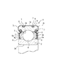
図1は、第1の実施形態に係る転がり軸受1を示しており、この転がり軸受1は、軌道輪である内輪2及び外輪3間に転動体4を配置して構成されている。転動体4は玉であり、複数の玉4が保持器5によって保持されている。この転がり軸受1には、一方の軌道輪(図示のものでは外輪3)にシールド6が取り付けられており、シールド軸受として構成されている。なお、シールド6は軸方向両端面に設けられている。
【0009】
軌道輪(図示のものでは外輪3の外周)には、クリープ防止のためのクリープ防止部としてOリング(弾性リング)7が装着されている。Oリング7は、例えばゴム製であり、軸方向に対をなして並設されている。なお、外輪3の外周面3aには、Oリング7を装着するための装着溝8が周方向に形成されている。また、この転がり軸受1にはグリースが封入されている。
前記軌道輪2,3は、軸受鋼などの金属製であり、転動体4はセラミック材料により形成されている。また、シールド6は、鉄板などの金属製である。
【0010】
例えば、この転がり軸受1が内輪回転で使用される場合、外輪3の外周面3a側にハウジングが取り付けられ、内輪2の内周面2a側に回転軸が取り付けられる。
転がり軸受1をハウジング等の他部材に装着させても、外輪3はクリープ防止部であるOリング7を介して他部材(ハウジング)に装着されるため、当該他部材にはOリング7が接するだけで、他部材と外輪外周面3aとは接しない状態にある。
したがって、外輪3に取り付けられる他部材が金属製でない場合はもちろん、他部材が金属製であっても、転がり軸受1から他部材(ハウジング)への熱の伝導(放熱)が妨げられた状態となっている。すなわち、他部材が熱伝導性の高い金属製であって、かつ外輪3と接していれば、転がり軸受1において発生した熱が他部材に伝導することによって放熱が促進されるが、他部材と外輪3との間に、熱伝導性の低いゴム製のOリング7が介在しているため、放熱が抑制された構造となっている。
【0011】
このように、本実施形態の転がり軸受1では、外輪3側における他部材との接触範囲がクリープ防止部であるOリング7の部分であり、このOリング7はゴム製であって非金属であるため非金属接触範囲となっている。なお、他部材が非金属であれば、転がり軸受1がOリング7を備えていなくても非金属接触範囲を有することとなり、この場合、転がり軸受1の外周面全体が非金属接触範囲となる。
Oリング7による非金属接触範囲によって妨げられた放熱を促進するため、前記外輪3及び前記シールド6,6には、表面処理9が施されている。この表面処理9は、外輪3及びシールド6,6の表面の放射率を高めるための処理である。ここでは、表面処理9は、軌道輪2,3やシールド6よりも放射率の高い材料をコーティングすることによってなされている。
【0012】
ここで、転がり軸受1の軌道輪2,3やシールド6の材料である金属は一般的に放射率が低いが、軌道輪2又はシールド6よりも放射率の高いコーティング9を施すことによって、コーティング9無しのものに比べて転がり軸受1からの放熱を促進することができる。
【0013】
放射範囲となるコーティング9は、放熱を行うべく、他部材と接しておらず転がり軸受1の露出した外表面となる範囲に形成する。他部材と接していない範囲としては、例えば、転がり軸受1の軸方向端面の範囲があるが、本実施形態では、外輪3及びシールド6にコーティング9が施されている。外輪3のコーティング9は、外輪3の外周面3a、内周面(軌道面を除く)3b、及び軸方向両端面3c,3cに施されている。また、内輪2にも軌道面を除き、同様にコーティング9を施すことができる。シールド6のコーティング9は、図示のものでは、シールド6のほぼ全表面に施されているが、少なくともシールド6の外表面6aに施すだけでも足りる。シールド表面のほぼ全体にコーティング9を施すことでコーティング表面積を広くでき放熱効率を大きくすることができる。また、外輪3とシールド6の双方にコーティング9を施すことでもコーティング面積を広くすることができている。つまり、コーティング9は、他部材に接触しない範囲の一部又は全部に施すことができ、軸受形状や使用条件、コスト等を考慮し、適宜、コーティング範囲を設定すればよい。
【0014】
なお、本実施形態では、シールド6が転がり軸受1の軸方向両側に設けられているが、シールド6が軸方向片側だけに存在するものであってもよい。さらに、シールド6が転がり軸受1の軸方向両側に設けられている場合に、図示のように両方のシールド6,6にコーティング9を施しても良いし、一方のシールド6だけにコーティング9を施しても良い。
【0015】
コーティング9の材料としては、放射率の高いものを適宜採用することができる。例えば、コーティング9は、セラミックコーティング又は放射率の高い金属酸化物のコーティングによって行うことができる。好ましくは、シリカ、アルミナ等の放射率の高い物質からなる粒子を分散させた無機系又は有機系のコーティングとすることができる。
また、コーティング9は、DLCなどの炭素系硬質膜を形成することによって行っても良い。あるいは、エポキシ樹脂などの樹脂材料でコーティングしてもよい。さらには、黒色塗装(好ましくは、つや消し黒色塗装)することによっても放射率を高くすることができる。
コーティング材料は、放射率の高いものであれば適宜採用できるが、セラミック材料、金属酸化物、DLC等の耐熱性を有するものを採用した場合には、高温環境での使用に耐えることができ好ましい。また、コーティングとしてセラミック材料を用いる場合には、セラミック材料による輻射によって特に優れた放熱性が得られる。
【0016】
本実施形態に係る転がり軸受1によれば、コーティング9によって形成された放射範囲によって、コーティング9のない転がり軸受1に比べて放熱性が高い。したがって、Oリング7によってハウジング等の他部材への放熱が妨げられている場合に、高速回転・高荷重など発熱を生じる条件下で転がり軸受1を使用しても、コーティング9からの放熱によって転がり軸受1の昇温を抑制することができる。よって、転がり軸受1の焼付きを防止できるとともに、グリースの劣化を防止できるため、転がり軸受1の寿命を長くすることができる。
しかも、本実施形態に係る転がり軸受1では、転動体に軽量のセラミックス材料が用いられているため、高速回転時における遠心力の軽減効果によって転がり軸受1からの発熱量も抑えられている。
【0017】
図2は、第2実施形態に係る転がり軸受1を示している。この転がり軸受1では、第1実施形態に係る転がり軸受1とは異なり外輪3にOリング7が設けられておらず、合成樹脂製の電気絶縁被膜10が形成されている。したがって、外輪3側に装着される他部材(ハウジング等)には電気絶縁皮膜10が接しており、外輪3は他部材に直接には接していない。
したがって、第2実施形態に係る転がり軸受1においても、外輪3に取り付けられる他部材が金属製でない場合はもちろん、他部材が金属製であっても、転がり軸受1から他部材(ハウジング)への熱の伝導(放熱)が電気絶縁皮膜10によって妨げられた状態となっている。すなわち、他部材と外輪3との間に、熱伝導性の低い合成樹脂製の電気絶縁皮膜10が介在しているため、放熱が抑制された構造となっている。
【0018】
このように、本実施形態の転がり軸受1では、外輪3側における他部材との接触範囲が電気絶縁皮膜10であり、この電気絶縁皮膜10は合成樹脂製であって非金属であるため非金属接触範囲となっている。
第2実施形態では、放熱を促進するためのコーティング9は、シールド6にだけ施されている。ただし、必要に応じて軌道輪2,3にも施してもよい。第2実施形態では、電気絶縁被膜10によって放熱が阻害されているがコーティング9によって放熱が促進され、昇温を抑制することができる。
なお、第2実施形態において、説明を省略した点は第1実施形態と同様である。また、図面においては同符号が附されている。
【0019】
【実施例】
図1に示す転がり軸受1の外輪3とシールド6に液体セラミックス(商品名:セラックα、セラック株式会社製)をスプレー、ディッピング等で塗布し、薄膜を形成してコーティングを行った。この転がり軸受1のコーティング9の放射率は約0.92であり、セラミックスによる輻射熱によって効率的な放熱が行われ、耐熱性にも優れる。
このコーティングされた転がり軸受を実施例とし、図1の転がり軸受1にコーティング9を施していないものを比較例とし、以下の条件で試験を行った。
<試験条件>
回転数:10000rpm
荷重:ラジアル荷重400kgfから24h毎に200kgf増加
潤滑:グリース(商品名:イソフレックスNBU15 空間の10%封入)
【0020】
図3に示すように、実施例では、比較例と比較して外輪温度が約10℃低く、昇温が抑制されている。しかも、実施例では、より高荷重まで運転が可能であることがわかる。したがって、同じ荷重であれば、実施例の方が、グリースの温度劣化が少なくグリース寿命が長くなり、転がり軸受として長寿命となる。
【0021】
【発明の効果】
本発明によれば、放射率を高める表面処理によって放熱が促進されるため、他部材との金属接触による放熱が抑制されていても、転がり軸受の昇温を抑えることができる。
【図面の簡単な説明】
【図1】第1実施形態に係る転がり軸受1の断面図である。
【図2】第2実施形態に係る転がり軸受2の断面図である。
【図3】試験結果を示すグラフである。
【符号の説明】
1 転がり軸受
2 内輪(軌道輪)
3 外輪(軌道輪)
4 玉(転動体)
7 Oリング(クリープ防止部;非金属接触範囲)
9 コーティング(表面処理)
10 電気絶縁皮膜(非金属接触範囲)[0001]
TECHNICAL FIELD OF THE INVENTION
The present invention relates to a rolling bearing.
[0002]
[Problems to be solved by the invention]
When a rolling bearing is used under high-speed rotation, high load conditions, etc., heat generation inside the rolling bearing becomes a problem. If the heat generation and the heat radiation are balanced, the temperature rise does not occur, but if the heat radiation amount is smaller than the heat generation amount, the temperature of the rolling bearing continues to rise.
[0003]
For example, when another metal member (shaft, housing, etc.) is attached to the raceway (inner ring / outer ring) of the rolling bearing, if heat is conducted to the other member to balance heat generation and heat dissipation, The temperature of the rolling bearing does not rise so much.
On the other hand, when the other member attached to the bearing ring is not made of metal, heat dissipation from the rolling bearing is generally not promoted due to low thermal conductivity and the temperature rises. If the race of the rolling bearing is provided with an elastic ring for preventing creep or an electric insulating coating, the rolling bearing will have an elastic ring for preventing creep or an electric insulating coating even if other members are made of metal. Therefore, heat is hardly transmitted from the rolling bearing to the other member through a member having low thermal conductivity, and the temperature rises because heat dissipation is not promoted.
[0004]
As described above, when the metal contact between the rolling bearing and the other member is broken, the temperature of the rolling bearing easily rises, and eventually seizure occurs. In the case of a rolling bearing in which grease is sealed, the grease deteriorates quickly and the life of the bearing is shortened. The present invention has been made in view of such a problem, and an object of the present invention is to suppress a temperature rise even in a rolling bearing in which heat dissipation is hindered.
[0005]
[Means for Solving the Problems]
The present invention relates to a rolling bearing having a raceway and a rolling element, and having a non-metallic contact area that comes into contact with other members attached to the raceway without making metallic contact. A rolling bearing characterized by having been subjected to a surface treatment for enhancing rolling resistance.
According to the present invention, as in the case where the other member is not metal, or the case where a member (rubber or resin or the like) having significantly lower thermal conductivity than the metal such as the anti-creep portion or the electric insulating film is provided on the raceway. Even if the rolling bearing has a non-metallic contact area, since the surface treatment for increasing the emissivity is performed, the heat radiation action from the area where the surface treatment is performed is improved, and the rolling without the surface treatment is performed. The temperature rise can be suppressed as compared with the bearing.
[0006]
The emissivity in the range where the surface treatment is performed is preferably 0.9 or more, and in this case, the temperature rise can be suppressed efficiently.
[0007]
Further, it is preferable that the surface treatment is a coating of a material having a heat resistance while increasing the emissivity of the rolling bearing. In this case, it becomes suitable for use at high temperatures. As the heat-resistant coating, a ceramic coating is preferable.
[0008]
BEST MODE FOR CARRYING OUT THE INVENTION
Hereinafter, preferred embodiments of the present invention will be described with reference to the drawings.
FIG. 1 shows a rolling bearing 1 according to a first embodiment. The rolling bearing 1 is configured by arranging a rolling element 4 between an
[0009]
An O-ring (elastic ring) 7 is mounted on the raceway (the outer periphery of the
The
[0010]
For example, when the rolling bearing 1 is used for inner ring rotation, a housing is attached to the outer
Even if the rolling bearing 1 is mounted on another member such as a housing, the
Therefore, not only when the other member attached to the
[0011]
As described above, in the rolling bearing 1 of the present embodiment, the contact area of the
The
[0012]
Here, the metal that is the material of the
[0013]
The
[0014]
In the present embodiment, the
[0015]
As the material of the
Further, the
The coating material can be appropriately used as long as it has a high emissivity. However, when a material having heat resistance such as a ceramic material, a metal oxide, or DLC is used, it can withstand use in a high-temperature environment, which is preferable. . Further, when a ceramic material is used as the coating, particularly excellent heat dissipation can be obtained by radiation from the ceramic material.
[0016]
According to the rolling bearing 1 according to the present embodiment, heat radiation is higher than that of the rolling bearing 1 without the
Moreover, in the rolling bearing 1 according to the present embodiment, since a lightweight ceramic material is used for the rolling element, the amount of heat generated from the rolling bearing 1 is suppressed by the effect of reducing the centrifugal force during high-speed rotation.
[0017]
FIG. 2 shows a rolling bearing 1 according to a second embodiment. In the rolling bearing 1, unlike the rolling bearing 1 according to the first embodiment, the
Therefore, also in the rolling bearing 1 according to the second embodiment, not only when the other member attached to the
[0018]
As described above, in the rolling bearing 1 of the present embodiment, the area of contact with other members on the
In the second embodiment, the
Note that, in the second embodiment, the points that are not described are the same as in the first embodiment. The same reference numerals are given in the drawings.
[0019]
【Example】
Liquid ceramics (trade name: Shellac α, manufactured by Shellac Co., Ltd.) was applied to the
The coated rolling bearing was taken as an example, and the rolling bearing 1 of FIG. 1 in which the
<Test conditions>
Rotation speed: 10000 rpm
Load: Radial load increased from 400 kgf to 200 kgf every 24 h Lubrication: Grease (trade name:
[0020]
As shown in FIG. 3, in the example, the outer ring temperature is lower by about 10 ° C. than in the comparative example, and the temperature rise is suppressed. Moreover, it can be seen that in the example, the operation can be performed up to a higher load. Therefore, if the load is the same, the embodiment has less grease temperature degradation and a longer grease life, resulting in a longer life as a rolling bearing.
[0021]
【The invention's effect】
According to the present invention, since the heat radiation is promoted by the surface treatment for increasing the emissivity, the temperature rise of the rolling bearing can be suppressed even if the heat radiation due to the metal contact with other members is suppressed.
[Brief description of the drawings]
FIG. 1 is a cross-sectional view of a rolling bearing 1 according to a first embodiment.
FIG. 2 is a sectional view of a rolling
FIG. 3 is a graph showing test results.
[Explanation of symbols]
1 rolling
3 Outer ring (track ring)
4 balls (rolling element)
7 O-ring (creep prevention part; non-metal contact area)
9 Coating (surface treatment)
10 Electrical insulation film (non-metal contact area)
Claims (5)
他部材に接触しない範囲に、放射率を高める表面処理が施されていることを特徴とする転がり軸受。In a rolling bearing having a raceway and a rolling element, and having a non-metallic contact range that comes into contact with other members attached to the raceway without making metal contact,
A rolling bearing characterized in that a surface treatment for increasing the emissivity is applied to a range not in contact with another member.
Priority Applications (1)
| Application Number | Priority Date | Filing Date | Title |
|---|---|---|---|
| JP2002246637A JP2004084792A (en) | 2002-08-27 | 2002-08-27 | Rolling bearing |
Applications Claiming Priority (1)
| Application Number | Priority Date | Filing Date | Title |
|---|---|---|---|
| JP2002246637A JP2004084792A (en) | 2002-08-27 | 2002-08-27 | Rolling bearing |
Publications (1)
| Publication Number | Publication Date |
|---|---|
| JP2004084792A true JP2004084792A (en) | 2004-03-18 |
Family
ID=32054480
Family Applications (1)
| Application Number | Title | Priority Date | Filing Date |
|---|---|---|---|
| JP2002246637A Pending JP2004084792A (en) | 2002-08-27 | 2002-08-27 | Rolling bearing |
Country Status (1)
| Country | Link |
|---|---|
| JP (1) | JP2004084792A (en) |
Citations (11)
| Publication number | Priority date | Publication date | Assignee | Title |
|---|---|---|---|---|
| JPH01112328U (en) * | 1988-01-22 | 1989-07-28 | ||
| JPH0314912A (en) * | 1989-06-09 | 1991-01-23 | Koyo Seiko Co Ltd | Rolling bearing |
| JPH04353295A (en) * | 1991-05-31 | 1992-12-08 | Daikin Ind Ltd | Vacuum pump |
| JPH05202944A (en) * | 1992-01-28 | 1993-08-10 | Mitsubishi Heavy Ind Ltd | Motion transmitter |
| JPH05283265A (en) * | 1992-04-03 | 1993-10-29 | Showa Denko Kk | Capacitor |
| JPH09144764A (en) * | 1995-11-22 | 1997-06-03 | Koyo Seiko Co Ltd | Rolling bearing |
| JPH10246238A (en) * | 1997-03-06 | 1998-09-14 | Ntn Corp | Rolling bearing and its attaching structure |
| JPH1130239A (en) * | 1997-05-12 | 1999-02-02 | Nippon Seiko Kk | Electrolytic corrosion preventive rolling bearing |
| JP2000213548A (en) * | 1999-01-22 | 2000-08-02 | Nsk Ltd | Electrolytic corrosion preventing rolling bearing |
| JP2001099176A (en) * | 1999-09-30 | 2001-04-10 | Ntn Corp | Sealed rolling bearing |
| JP2002147468A (en) * | 2000-11-10 | 2002-05-22 | Koyo Seiko Co Ltd | Insulation bearing |
-
2002
- 2002-08-27 JP JP2002246637A patent/JP2004084792A/en active Pending
Patent Citations (11)
| Publication number | Priority date | Publication date | Assignee | Title |
|---|---|---|---|---|
| JPH01112328U (en) * | 1988-01-22 | 1989-07-28 | ||
| JPH0314912A (en) * | 1989-06-09 | 1991-01-23 | Koyo Seiko Co Ltd | Rolling bearing |
| JPH04353295A (en) * | 1991-05-31 | 1992-12-08 | Daikin Ind Ltd | Vacuum pump |
| JPH05202944A (en) * | 1992-01-28 | 1993-08-10 | Mitsubishi Heavy Ind Ltd | Motion transmitter |
| JPH05283265A (en) * | 1992-04-03 | 1993-10-29 | Showa Denko Kk | Capacitor |
| JPH09144764A (en) * | 1995-11-22 | 1997-06-03 | Koyo Seiko Co Ltd | Rolling bearing |
| JPH10246238A (en) * | 1997-03-06 | 1998-09-14 | Ntn Corp | Rolling bearing and its attaching structure |
| JPH1130239A (en) * | 1997-05-12 | 1999-02-02 | Nippon Seiko Kk | Electrolytic corrosion preventive rolling bearing |
| JP2000213548A (en) * | 1999-01-22 | 2000-08-02 | Nsk Ltd | Electrolytic corrosion preventing rolling bearing |
| JP2001099176A (en) * | 1999-09-30 | 2001-04-10 | Ntn Corp | Sealed rolling bearing |
| JP2002147468A (en) * | 2000-11-10 | 2002-05-22 | Koyo Seiko Co Ltd | Insulation bearing |
Similar Documents
| Publication | Publication Date | Title |
|---|---|---|
| JP5518699B2 (en) | Bearing components for rolling bearings or sliding bearings | |
| EP3048340B1 (en) | Sealing arrangement | |
| JP2013199954A (en) | Insulation rolling bearing for electrolytic corrosion prevention | |
| JP2014092225A (en) | Rolling bearing | |
| JP2004251412A (en) | Rolling bearing | |
| JP6458414B2 (en) | Vacuum pump | |
| JP2004084792A (en) | Rolling bearing | |
| JP2001153145A (en) | Hermetically sealed rolling bearing | |
| KR102754877B1 (en) | Anode rotating type x-ray tube having liquid metal lubricated sliding bearing | |
| JP2001323941A (en) | Vehicular rotary device | |
| JP2002227845A (en) | Rolling bearing | |
| CN1945039B (en) | Rolling bearing | |
| JP2019007580A (en) | Bearing with wireless sensor | |
| JP2008157409A (en) | Hub unit bearing with braking member | |
| JP2004308735A (en) | Electric corrosion-proof bearing | |
| JP4548334B2 (en) | Rolling bearing | |
| JP6559450B2 (en) | High circumferential magnetic fluid seal structure | |
| KR102747835B1 (en) | Liquid metal lubricated sliding bearing usable in high temperature and vacuum atmosphere | |
| JP2010203492A (en) | Rolling bearing device | |
| JP2001041232A (en) | Full type ball bearing for oscillation part | |
| WO2023238392A1 (en) | Rolling bearing | |
| JP3361159B2 (en) | Rolling bearing for vacuum equipment | |
| US11043859B2 (en) | Permanent magnet rotating electric machine | |
| JPH0145081Y2 (en) | ||
| JP2004144268A (en) | Rolling bearing |
Legal Events
| Date | Code | Title | Description |
|---|---|---|---|
| A621 | Written request for application examination |
Free format text: JAPANESE INTERMEDIATE CODE: A621 Effective date: 20050506 |
|
| A977 | Report on retrieval |
Free format text: JAPANESE INTERMEDIATE CODE: A971007 Effective date: 20071101 |
|
| A131 | Notification of reasons for refusal |
Free format text: JAPANESE INTERMEDIATE CODE: A131 Effective date: 20071120 |
|
| A521 | Written amendment |
Free format text: JAPANESE INTERMEDIATE CODE: A523 Effective date: 20080117 |
|
| A131 | Notification of reasons for refusal |
Free format text: JAPANESE INTERMEDIATE CODE: A131 Effective date: 20080603 |
|
| A521 | Written amendment |
Free format text: JAPANESE INTERMEDIATE CODE: A523 Effective date: 20080723 |
|
| A02 | Decision of refusal |
Free format text: JAPANESE INTERMEDIATE CODE: A02 Effective date: 20080916 |