JP2004078209A - Holding device, exposing device and device manufacturing method - Google Patents
Holding device, exposing device and device manufacturing method Download PDFInfo
- Publication number
- JP2004078209A JP2004078209A JP2003284530A JP2003284530A JP2004078209A JP 2004078209 A JP2004078209 A JP 2004078209A JP 2003284530 A JP2003284530 A JP 2003284530A JP 2003284530 A JP2003284530 A JP 2003284530A JP 2004078209 A JP2004078209 A JP 2004078209A
- Authority
- JP
- Japan
- Prior art keywords
- holding device
- groove
- optical member
- holding
- grooves
- Prior art date
- Legal status (The legal status is an assumption and is not a legal conclusion. Google has not performed a legal analysis and makes no representation as to the accuracy of the status listed.)
- Withdrawn
Links
Images


Abstract
Description
本発明は、一般には、光学部材を搭載する精密機器、特に、露光装置等の投影光学系に関し、更に詳細には、半導体素子、撮像素子(CCD等)又は薄膜磁気ヘッド等を製造するためのリソグラフィー工程に使用される露光装置において、原版(例えば、マスク又はレチクル(なお、本出願では、これらの用語を交換可能に使用する。))の像を被処理体に投影露光する際、より正確な結像関係を得るための光学部材の保持装置に関する。 The present invention generally relates to a precision instrument on which an optical member is mounted, in particular, to a projection optical system such as an exposure apparatus, and more particularly, to a semiconductor device, an imaging device (such as a CCD) or a thin film magnetic head. In an exposure apparatus used in a lithography process, when an image of an original (for example, a mask or a reticle (the terms are used interchangeably in the present application)) is projected and exposed on an object to be processed, it is more accurate. TECHNICAL FIELD The present invention relates to a holding device for an optical member for obtaining a proper imaging relationship.
フォトリソグラフィー(焼き付け)技術を用いてデバイスを製造する際に、マスクに描画された回路パターンを投影光学系によってウェハ等に投影して回路パターンを転写する縮小投影露光装置が従来から使用されている。投影光学系は、回路パターンからの回折光をウェハの上に干渉させて結像させる。 2. Description of the Related Art When manufacturing a device using a photolithography (printing) technique, a reduction projection exposure apparatus that transfers a circuit pattern by projecting a circuit pattern drawn on a mask onto a wafer or the like by a projection optical system has been conventionally used. . The projection optical system forms an image by causing the diffracted light from the circuit pattern to interfere with the wafer.
近年の電子機器の小型化及び薄型化への要請を実現するためには、電子機器に搭載されるデバイスを高集積化する必要があり、転写される回路パターンの微細化、即ち、高解像度化がますます要求されている。高解像力を得るためには、露光光の波長を短くすること、及び、投影光学系の開口数(NA)を上げることが有効であり、同時に投影光学系の収差を極めて小さく抑えなくてはならない。 In order to meet the recent demand for smaller and thinner electronic devices, it is necessary to highly integrate devices mounted on the electronic devices, and finer circuit patterns to be transferred, that is, higher resolution Are increasingly required. In order to obtain a high resolution, it is effective to shorten the wavelength of the exposure light and increase the numerical aperture (NA) of the projection optical system, and at the same time, the aberration of the projection optical system must be extremely small. .
投影光学系を構成するレンズ、ミラーなどの光学素子に変形が生じると、変形前後で光路が屈折し、一点に結像するべき光線が一点に収束せずに収差を生じる。収差は位置ずれを招いてウェハ上の回路パターンの短絡を招く。一方、短絡を防止するためにパターン寸法を広くすれば微細化の要求に反する。 (4) When deformation occurs in an optical element such as a lens or a mirror that constitutes a projection optical system, an optical path is refracted before and after the deformation, and a ray to be imaged at one point does not converge at one point, causing an aberration. The aberration causes a displacement and a short circuit of the circuit pattern on the wafer. On the other hand, if the pattern size is increased in order to prevent a short circuit, it is against the demand for miniaturization.
従って、収差が小さい投影光学系を実現するためには、投影光学系を構成する光学素子の形状及び光軸に対する位置を変化させることなく投影光学系内に保持して、光学素子が有する本来の光学的性能を最大限に引き出す必要がある。特に、近年の投影光学系の高NA化により、投影レンズは大口径化しているのでレンズ容積も大きくなり、自重による変形が発生しやすくなっている。また、最近盛んに研究が進められている極端紫外線(EUV:extreme ultraviolet)光を用いた露光装置は、その特徴の一つである短波長のEUV光(波長約10nm乃至15nm程度)のために少数の反射素子(即ち、ミラー)で投影光学系を構成しなければならず、ミラーの形状及び光軸に対する位置精度は極めて厳しい。 Therefore, in order to realize a projection optical system with small aberration, the shape and the position of the optical element constituting the projection optical system with respect to the optical axis are held in the projection optical system without changing, and the original It is necessary to maximize optical performance. In particular, with the recent increase in the NA of the projection optical system, the diameter of the projection lens has been increased, so that the volume of the lens has also been increased, and deformation due to its own weight has been likely to occur. An exposure apparatus using extreme ultraviolet (EUV) light, which has been actively studied recently, has a short wavelength EUV light (wavelength of about 10 nm to 15 nm) which is one of its features. The projection optical system must be composed of a small number of reflecting elements (that is, mirrors), and the shape of the mirror and the positional accuracy with respect to the optical axis are extremely severe.
EUV露光装置は、0.1μm以下の回路パターンの露光に使用されるため、線幅精度が非常に厳しく、ミラーの形状においては、0.1nm程度以下の変形しか許されない。従って、ミラーの加工時の形状をEUV露光装置に組み込む際に、正確に再現する必要がある。 (4) Since the EUV exposure apparatus is used for exposure of a circuit pattern of 0.1 μm or less, the line width accuracy is very strict, and the mirror shape is allowed to have a deformation of about 0.1 nm or less. Therefore, it is necessary to accurately reproduce the mirror processing shape when incorporating the mirror into an EUV exposure apparatus.
しかし、ミラーを構成する母材料は非常に柔らかく、ミラーを保持する保持部材が加える力(保持力)だけでもミラーは0.1nm程度の変形を生じてしまう。また、保持部材の熱膨張や振動、変形によってミラーの位置ずれが発生してしまう。更には、ミラーは、全ての露光光を反射するわけではなく、30%以上の露光光を吸収してしまうため、吸収した露光光が分熱となりミラーを熱膨張させ、ミラーの形状及び光軸に対する位置を変化させてしまう。従って、ミラーの形状及び光軸に対する位置を変化させることなく投影光学系内に保持し、所望の光学性能を発揮させることができなかった。 However, the base material of the mirror is very soft, and the mirror is deformed by about 0.1 nm only by the force (holding force) applied by the holding member holding the mirror. In addition, the displacement of the mirror is caused by thermal expansion, vibration, and deformation of the holding member. Furthermore, the mirror does not reflect all of the exposure light, but absorbs more than 30% of the exposure light, so that the absorbed exposure light is split into heat and thermally expands the mirror. Changes the position with respect to. Therefore, the mirror cannot be held in the projection optical system without changing its shape and position with respect to the optical axis, and the desired optical performance cannot be exhibited.
そこで、本発明は、結像性能の劣化となる光学部材の変形及び位置ずれによる収差を低減することで所望の光学性能をもたらす保持装置、露光装置及びデバイス製造方法を提供することを例示的目的とする。 Accordingly, it is an exemplary object of the present invention to provide a holding apparatus, an exposure apparatus, and a device manufacturing method that provide desired optical performance by reducing aberration due to deformation and displacement of an optical member that deteriorates imaging performance. And
上記目的を達成するために、本発明の一側面としての保持装置は、3つの第1の溝を有する光学部材を保持する保持装置であって、光学部材を第1の溝を介して支持する第1の支持部材と、第1の溝に対応する3つの第2の溝を有し、第2の溝を介して第1の支持部材を支持する第2の支持部材(固定部材)とを有することを特徴とする。 In order to achieve the above object, a holding device according to one aspect of the present invention is a holding device that holds an optical member having three first grooves, and supports the optical member via the first grooves. A first support member, and a second support member (fixing member) having three second grooves corresponding to the first grooves and supporting the first support member via the second grooves. It is characterized by having.
本発明の別の側面としての保持装置は、第1の溝が半径方向に沿った直線上の溝であることを特徴とする。 保持 A holding device as another aspect of the present invention is characterized in that the first groove is a linear groove along the radial direction.
本発明の更に別の側面としての保持装置は、3つの第1の溝又はその延長線が略1点で交わることを特徴とする。 保持 A holding device as yet another aspect of the present invention is characterized in that three first grooves or their extensions intersect at substantially one point.
本発明の更に別の側面としての保持装置は、3つの第2の溝又はその延長線が略1点で交わることを特徴とする。 保持 A holding device as yet another aspect of the present invention is characterized in that three second grooves or their extensions intersect at substantially one point.
本発明の更に別の側面としての保持装置は、3つの第1の溝又は3つの第2の溝のうち少なくとも一方が螺旋状の形状を有していることを特徴とする。 保持 A holding device as still another aspect of the present invention is characterized in that at least one of the three first grooves or the three second grooves has a spiral shape.
本発明の更に別の側面としての保持装置は、3つの第1の溝のうち一の第1の溝又はその延長線が他の第1の溝又はその延長線と交わる点と、一の第1の溝又はその延長線が残りの第1の溝又はその延長線と交わる点とが異なることを特徴とする。 According to still another aspect of the present invention, there is provided a holding device in which one of the three first grooves or an extension thereof intersects with the other first groove or an extension thereof, and It is characterized in that a point where one groove or its extension line intersects with the remaining first groove or its extension line is different.
本発明の更に別の側面としての保持装置は、3つの第2の溝のうち一の第2の溝又はその延長線が他の第2の溝又はその延長線と交わる点と、一の第2の溝又はその延長線が残りの第2の溝又はその延長線と交わる点とが異なることを特徴とする。 According to still another aspect of the present invention, there is provided a holding device in which one of the three second grooves or an extension thereof intersects another second groove or an extension thereof, and The second groove or its extension is different from the intersection with the remaining second groove or its extension.
本発明の更に別の側面としての保持装置は、上記の略1点が光学部材の中心であることを特徴とする請求項3記載の保持装置。 保持 The holding device according to claim 3, wherein the substantially one point is a center of the optical member.
本発明の更に別の側面としての保持装置は、上記の略1点が光学部材の中心以外の点であることを特徴とする。 保持 A holding device as still another aspect of the present invention is characterized in that the above-mentioned approximately one point is a point other than the center of the optical member.
本発明の更に別の側面としての保持装置は、3つの第2の溝又はその延長線が略1点で交わることを特徴とする。 保持 A holding device as yet another aspect of the present invention is characterized in that three second grooves or their extensions intersect at substantially one point.
本発明の更に別の側面としての保持装置は、3つの第1の溝がお互いに120度をなし、3つの第2の溝がお互いに120度をなしていることを特徴とする。 保持 A holding device according to yet another aspect of the present invention is characterized in that three first grooves form 120 degrees with each other and three second grooves form 120 degrees with each other.
本発明の更に別の側面としての保持装置は、第1の溝及び第2の溝は断面がV字形状であることを特徴とする。 保持 A holding device as still another aspect of the present invention is characterized in that the first groove and the second groove have a V-shaped cross section.
本発明の更に別の側面としての保持装置は、断面V字形状が略90°の角度であることを特徴とする。 保持 A holding device as still another aspect of the present invention is characterized in that the V-shaped cross section has an angle of about 90 °.
本発明の更に別の側面としての保持装置は、第1の支持部材が真球体形状を有することを特徴とする。 保持 A holding device as still another aspect of the present invention is characterized in that the first support member has a spherical shape.
本発明の更に別の側面としての保持装置は、第1の支持部材が、第1の溝及び第2の溝に沿って転動可能であることを特徴とする。 保持 A holding device as still another aspect of the present invention is characterized in that the first support member is rollable along the first groove and the second groove.
本発明の更に別の側面としての保持装置は、光学部材の中心から光学部材の半径の60%乃至70%離れた位置において、光学部材と第1の支持部材とが接触することを特徴とする。 In a holding device according to still another aspect of the present invention, the optical member and the first support member are in contact with each other at a position 60% to 70% of the radius of the optical member from the center of the optical member. .
本発明の更に別の側面としての保持装置は、外周に3つの球面形状の凸部を有する光学部材を保持する保持装置であって、光学部材の半径方向に沿う方向に球面形状の凸部を載置するための断面略V字形状の溝を有し、当溝を介して光学部材を保持する保持部材を有することを特徴とする。 A holding device as still another aspect of the present invention is a holding device for holding an optical member having three spherical convex portions on an outer periphery, and includes a spherical convex portion in a direction along a radial direction of the optical member. It has a groove having a substantially V-shaped cross section for mounting, and a holding member for holding the optical member through the groove.
本発明の更に別の側面としての保持装置は、保持部材が光学部材の半径方向に移動可能であることを特徴とする。 保持 A holding device as still another aspect of the present invention is characterized in that the holding member is movable in the radial direction of the optical member.
本発明の更に別の側面としての保持装置は、3つの球面形状の凸部が、光学部材の中心に関して120度のピッチで配置されることを特徴とする。 保持 A holding device as still another aspect of the present invention is characterized in that three spherical projections are arranged at a pitch of 120 degrees with respect to the center of the optical member.
本発明の更に別の側面としての保持装置は、溝を構成する2つの支持平面の各々を、当支持平面に対して垂直方向に駆動する駆動機構を更に有することを特徴とする。 保持 A holding device as still another aspect of the present invention is characterized by further having a drive mechanism for driving each of two support planes forming a groove in a direction perpendicular to the support plane.
本発明の更に別の側面としての保持装置は、上記の凸部が断面V字形状の孔を有し、当孔を介して球面に圧力を付加する圧力付加手段を更に有することを特徴とする。 A holding device as still another aspect of the present invention is characterized in that the projection has a hole having a V-shaped cross section, and further has pressure applying means for applying pressure to the spherical surface through the hole. .
本発明の更に別の側面としての保持装置は、外周に3つのV字形状の凸部を有する光学部材を保持する保持装置であって、V字形状の凸部を挟むように接触する2つの球面部を有し、当球面部を介して光学部材を保持する保持部材を有することを特徴とする。 A holding device as still another aspect of the present invention is a holding device for holding an optical member having three V-shaped protrusions on the outer periphery, and two holding members that are in contact with each other so as to sandwich the V-shaped protrusion. It has a spherical portion, and has a holding member for holding the optical member via the spherical portion.
本発明の更に別の側面としての保持装置は、保持部材が、光学部材の半径方向に沿う方向に移動可能であることを特徴とする。 保持 A holding device as still another aspect of the present invention is characterized in that the holding member is movable in a direction along a radial direction of the optical member.
本発明の更に別の側面としての保持装置は、3つのV字形状の凸部が、光学部材の中心に関して120度のピッチで配置されることを特徴とする。 保持 A holding device as still another aspect of the present invention is characterized in that three V-shaped protrusions are arranged at a pitch of 120 degrees with respect to the center of the optical member.
本発明の更に別の側面としての保持装置は、光学部材がミラーであることを特徴とする。 保持 A holding device as still another aspect of the present invention is characterized in that the optical member is a mirror.
本発明の更に別の側面としての露光装置は、請求項2に記載の保持装置を備え、当保持装置に保持された光学部材を介してマスク又はレチクルに形成されたパターンを被処理体に露光する光学系を有することを特徴とする。
An exposure apparatus as still another aspect of the present invention includes the holding device according to
本発明の更に別の側面としての露光装置は、請求項3に記載の保持装置を備え、当保持装置に保持された光学部材を介してマスク又はレチクルに形成されたパターンを被処理体に露光する光学系を有することを特徴とする。 An exposure apparatus as still another aspect of the present invention includes the holding device according to claim 3, and exposes a pattern formed on a mask or a reticle to an object to be processed through an optical member held by the holding device. It is characterized by having an optical system to perform.
本発明の更に別の側面としての保持装置は、請求項17に記載の保持装置を備え、当保持装置に保持された光学部材を介してマスク又はレチクルに形成されたパターンを被処理体に露光する光学系を有することを特徴とする。 A holding device as still another aspect of the present invention includes the holding device according to claim 17, and exposes a pattern formed on a mask or a reticle to an object to be processed through an optical member held by the holding device. It is characterized by having an optical system to perform.
本発明の更に別の側面としての露光装置は、請求項22に記載の保持装置を備え、当保持装置に保持された光学部材を介してマスク又はレチクルに形成されたパターンを被処理体に露光する光学系を有することを特徴とする。 An exposure apparatus as still another aspect of the present invention includes the holding device according to claim 22, and exposes a pattern formed on a mask or a reticle to an object to be processed through an optical member held by the holding device. It is characterized by having an optical system to perform.
本発明の更に別の側面としてのデバイス製造方法は、請求項26に記載の露光装置を用いて被処理体を投影露光するステップと、投影露光された被処理体に所定のプロセスを行うステップとを有することを特徴とする。 A device manufacturing method according to still another aspect of the present invention includes a step of projecting and exposing an object to be processed by using the exposure apparatus according to claim 26, and a step of performing a predetermined process on the object to be projected and exposed. It is characterized by having.
本発明の更に別の側面としてのデバイス製造方法は、請求項27に記載の露光装置を用いて被処理体を投影露光するステップと、投影露光された被処理体に所定のプロセスを行うステップとを有することを特徴とする。 A device manufacturing method according to still another aspect of the present invention includes a step of projecting and exposing an object to be processed using the exposure apparatus according to claim 27, and a step of performing a predetermined process on the object to be projected and exposed. It is characterized by having.
本発明の更に別の側面としてのデバイス製造方法は、請求項28に記載の露光装置を用いて被処理体を投影露光するステップと、投影露光された被処理体に所定のプロセスを行うステップとを有することを特徴とする。 A device manufacturing method as still another aspect of the present invention includes a step of projecting and exposing an object to be processed by using the exposure apparatus according to claim 28, and a step of performing a predetermined process on the object to be projected and exposed. It is characterized by having.
本発明の更に別の側面としてのデバイス製造方法は、請求項29に記載の露光装置を用いて被処理体を投影露光するステップと、投影露光された被処理体に所定のプロセスを行うステップとを有することを特徴とする。上述の露光装置の作用と同様の作用を奏するデバイス製造方法の請求項は、中間及び最終結果物であるデバイス自体にもその効力が及ぶ。また、かかるデバイスは、LSIやVLSIなどの半導体チップ、CCD、LCD、磁気センサー、薄膜磁気ヘッドなどを含む。 A device manufacturing method according to still another aspect of the present invention includes a step of projecting and exposing an object to be processed using the exposure apparatus according to claim 29, and a step of performing a predetermined process on the object to be projected and exposed. It is characterized by having. The claims of the device manufacturing method having the same operation as that of the above-described exposure apparatus extend to the device itself as an intermediate and final product. Such devices include semiconductor chips such as LSI and VLSI, CCDs, LCDs, magnetic sensors, thin-film magnetic heads, and the like.
本発明の更なる目的又はその他の特徴は、以下添付図面を参照して説明される好ましい実施例によって明らかにされるであろう。 Further objects and other features of the present invention will become apparent from the preferred embodiments described below with reference to the accompanying drawings.
本発明の保持装置によれば、結像性能の劣化となる光学部材の変形及び位置ずれによる収差を低減することで所望の光学性能を達成することができる。 According to the holding device of the present invention, desired optical performance can be achieved by reducing aberrations due to deformation and displacement of the optical member, which deteriorates imaging performance.
以下、添付図面を参照して、本発明の例示的な保持装置及び露光装置について説明する。但し、本発明はこれらの実施例に限定するものではなく、本発明の目的が達成される範囲において、各構成要素が代替的に置換されてもよい。例えば、本実施形態では、保持装置100を例示的に露光装置500の投影光学系530に適用しているが、露光装置500の照明光学系514、その他周知のいかなる光学系に適用してもよい。ここで、図1は、本発明の一側面としての保持装置100を示す概略構成図であって、図1(a)は保持装置100の斜視図、図1(b)は光学部材110を保持した保持装置100の断面図である。
Hereinafter, exemplary holding devices and exposure devices of the present invention will be described with reference to the accompanying drawings. However, the present invention is not limited to these embodiments, and each component may be replaced as long as the object of the present invention is achieved. For example, in the present embodiment, the holding
保持装置100は、図1によく示されるように、支持部材120第1の支持部材)及び固定部材(第2の支持部材)130とを有する。保持装置100は、投影光学系530に適用され、支持部材120及び固定部材130を介して光学部材110を保持する。
The holding
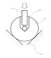
光学部材110は、後述する支持部材120に第1の溝116を介して載置され、反射、屈折及び回折等を利用して光を結像させる。光学部材110は、本実施形態では、例示的にミラーとして構成されているが、例えば、ミラー、レンズ、平行平板ガラス、プリズム及びフレネルゾーンプレート、キノフォーム、バイナリオプティックス、ホログラム等の回折光学素子を含む。光学部材110は、図2に示すように、光を反射する反射面112の反対側の底面114(即ち、支持部材120側)の3箇所に断面V字形状の第1の溝116を有する。ここで、図2は、図1に示す光学部材110の概略斜視図である。
The
第1の溝116は、光学部材110の底面114の中心Oから120°ピッチで開いた半径方向に配置されている。第1の溝116は、後述する支持部材120に載置され、第1の溝116を介して光学部材110が保持される。このように、第1の溝116は、光学部材110の円周方向に沿ってほぼ等間隔で分布しているために光学部材110は、支持部材120上で安定する。第1の溝116は、光学部材110の自重変形による撓みが最も少なくなるように、半径方向において中心Oから光学部材110の半径の60%乃至70%離れた位置で支持部材120と光学部材の第1の溝116とが接触するように配置することが好ましい。従って、第1の溝116を、光学部材110の半径方向に中心Oから半径の50〜80%の位置、もしくはこの範囲内の位置に形成するのが好ましい。勿論、第1の溝116自体を図2のように、60〜70%の位置形成しても良い。
The
支持部材120は、真球体形状を有する部材であり、第1の溝116と接する。支持部材120は、第1の溝116を介して光学部材110を支持する。支持部材120は、例えば、実質的に光学部材110の線膨張率と等しい線膨張率を有する材料から構成される。このように構成すれば、温度環境変動時に、線膨張率の違いから生じる光学部材110と支持部材120の相対変位により、支持部材120が第1の溝116から外れたり、第1の溝116を介して光学部材110に外力を与えて変形させたりすることを防止することができる。
The
固定部材130は、支持部材120に関して光学部材110と対向する側に配置される。固定部材130は、光学部材110側の面の3箇所に断面V字形状の第2の溝132を有し、第2の溝132を介して支持部材120を固定する。
The fixing
第2の溝132は、中心Oから120°ピッチで開いた半径方向に配置される。換言すれば、第2の溝132は、光学部材110の底面114に配置された第1の溝116と対向する位置に配置される。第2の溝132は、支持部材120を半径方向に移動可能に(即ち、半径方向に自由度をもって)載置する。即ち、第2の溝132は、支持部材120の円周方向の動きを規定すると共に、真球体形状の支持部材120が半径方向に転がれるように形成される。従って、第2の溝132によって、温度環境変動時に、光学部材110又は固定部材130の熱膨張が生じても半径方向に膨張を許容することができるため、光学部材110の中心Oが光軸に対して位置ずれを起こすことを防止することができる。
The
保持装置100は、固定部材130の第2の溝132に支持部材140を載置し、更に、支持部材140の上に第1の溝116が接するように光学部材110を載置して光学部材110を保持する。光学部材110の第1の溝116及び固定部材130の第2の溝132は、図3に示すように、断面V字形状の角度θが略90°であるため、光学部材110(の第1の溝116)と支持部材120は2点A1及びA2で接触し、支持部材120と固定部材130(の第2の溝132)も2点B1及びB2で接触する。また、支持部材120は、第1の溝116及び第2の溝132と2点で接触するように設計されている。従って、保持装置100全体としては、光学部材110は6点で支持部材120に支持され、支持部材120は6点で固定部材130に支持されることになり、キネマティック支持となる。光学部材110の位置は、光学部材110の自重により支持部材120が固定部材130に対して固定されるため、一義的に決定する。従って、保持装置100は、第1の溝116を光学部材110の中心Oから60%乃至70%離れた位置に配置することで光学部材の自重変形を最小にすることができ、固定部材130の第2の溝132に沿って半径方向に移動可能な支持部材120により光学部材110をキネマティックに支持することで、結像性能の劣化となる光学部材110の変形及び位置ずれによる収差を低減することで所望の光学性能を達成することができる。なお、光学部材110が透過部材である場合には、光を遮らないように、光学部材110の透過領域にあわせて固定部材130に孔を設ければよいし、光に対して透過性の固定部材130を使用してもよい。ここで、図3は、保持装置100が光学部材110を保持した状態における光学部材110の第1の溝116、支持部材120及び固定部材130の第2の溝132を示す概略断面図である。
The holding
ここで、第1の溝116及び第2の溝132は、ここでは光学部材の中心Oを中心にして、120度ピッチで形成しているが、この限りでは無く、第1の溝116と第2の溝132とが対応していれば、120度以外の角度でも構わない。但し、3本の溝のそれぞれの間の3つの角度は、その3つの角度のうち2つの角度が等しくなるように構成することが好ましく、その等しくなる2つの角度は120度より大きくすること、特に150度以上になるように構成することが好ましい。
Here, the
さらに、第1の溝は、必ずしも半径方向に沿って延びるように配置されている必要はなく、例えば図15に示されるように配置されていても構わない。図15は、第1の溝116Aが形成された保持装置100の平面図である。この3本の第1の溝116Aは、そのうちの一の第1の溝116a又はその延長線が他の第1の溝116b又はその延長線と交わる点と、一の第1の溝116a又はその延長線が残りの第1の溝116c又はその延長線と交わる点とが異なるように形成されている。
Furthermore, the first groove does not necessarily need to be arranged to extend in the radial direction, and may be arranged as shown in FIG. 15, for example. FIG. 15 is a plan view of the holding
また、第1の溝は、必ずしも直線状に配置されている必要もなく、例えば図16(a)に示されるように、1本の螺旋状の第1の溝116Bが保持装置100に形成されていてもよい。さらに、例えば図16(c)に示されるように、3本の螺旋状の第1の溝116Dが保持装置100の中心で交わり、互いに等間隔に螺旋を描きながら広がるように形成されていてももちろんよい。
In addition, the first grooves do not necessarily have to be arranged in a straight line. For example, as shown in FIG. 16A, one spiral
これらのことは、第1の溝についてのみならず、第2の溝についても同様のことが言える。すなわち、第2の溝132も、必ずしも半径方向に沿って延びている必要はなく、また、直線状である必要もない。
The same can be said for not only the first groove but also the second groove. That is, the
ここで、前述の第1の溝と第2の溝は、両者が光学部材の半径方向に沿った3つの溝を具備し、それぞれの3つの溝同士が対応する位置(光学部材の中心に関して同じ角度をなしている状態、或いはそれぞれの3つの溝がお互いになす角度が等しい状態)にあるようにすれば、この保持装置によって、光学部材を固定することが可能になる。 Here, each of the first groove and the second groove has three grooves along the radial direction of the optical member, and each of the three grooves corresponds to a corresponding position (the same position with respect to the center of the optical member). The optical member can be fixed by the holding device if the angled state or the angle formed by each of the three grooves is equal to each other.
また、3つの第1の溝が交わる、或いは3つの第1の溝が延長線上において交わるように構成し、3つの第2の溝も交わる或いは3つの第2の溝が延長線上において交わるように構成すれば、同様にこの保持装置によって光学部材を固定することができる。ここで、3つの溝が交わる略1点(溝の幅の分だけ広がりがあり、さらに微小ならずれていても構わない)は、前記光学部材の中心であるのが好ましい。しかし、中心以外であっても構わない。 In addition, three first grooves intersect or three first grooves intersect on an extension line, and three second grooves also intersect or three second grooves intersect on an extension line. With this configuration, the optical member can be similarly fixed by the holding device. Here, it is preferable that approximately one point where the three grooves intersect (the width is widened by the width of the groove, and may be finer) is the center of the optical member. However, it may be other than the center.
また、支持部材120(第1の支持部材)が真球体形状を有することが好ましいが、第1の溝或いは第2の溝と接触する領域だけが球体形状を有していれば良いので、必ずしも真球体形状でなくても構わない。 Further, it is preferable that the support member 120 (first support member) has a true sphere shape, but it is only necessary that only a region in contact with the first groove or the second groove has a sphere shape. The shape need not be a true sphere.
次に、図4乃至図8を参照して、別の保持装置200について説明する。図4は、本発明の一側面としての別の保持装置200を示す概略構成図である。保持装置200は、投影光学系530に適用され、図4によく示されるように、保持部材220を介して光学部材210を保持する。
Next, another holding
光学部材210は、後述する保持部材220に凸部を介して載置され、反射、屈折及び回折等を利用して光を結像させる。光学部材210は、例えば、ミラー、レンズ、平行平板ガラス、プリズム及びフレネルゾーンプレート、キノフォーム、バイナリオプティックス、ホログラム等の回折光学素子を含む。光学部材110は、図5に示すように、外周に3つの球面形状の凸部212を有する。ここで、図5は、図1に示す光学部材210の概略斜視図である。
The
3つの球面形状の凸部212は、120°ピッチで配置されている。このように、光学部材210の円周方向に沿ってほぼ等間隔で分布しているために光学部材210は、保持部材220上で安定する。凸部212は、本実施形態では、光学部材210と一体で構成されているため、光学部材210に凸部212を接合する際に、光学部材210に力が加わり、表面形状が変化してしまうことがない。但し、光学部材210に凸部212を接合することで光学部材210の表面形状が変化しない、又は、表面形状の変化が許容範囲内であるならば、光学部材210と凸部212を別体として構成してもよい。
The three
保持部材220は、光学部材210の半径方向に沿う方向に、光学部材210の外周に設けられた3つの球面形状の凸部212を載置するための断面V字形状の溝222を有し、かかる溝222を介して光学部材210を保持する。保持部材220は、光学部材210の外周に設けられた凸部212にあわせて配置される。保持部材220は、光学部材210の半径方向のみに自在に移動可能で、動径方向や他の方向には十分な剛性を有する弾性部材、例えば、平行板バネから構成される。保持部材220は、光学部材210の球面形状の凸部212を断面V字形状の溝222に載置する際に、平行板バネの十分柔らかな板バネ剛性を利用して、凸部212と溝222との間に発生する摩擦力による光学部材210の変形を小さくすることができる。また、保持部材220は、半径方向に移動可能であることで、光学部材210の熱膨張に対しても中心Oから等方的な伸びは逃がし位置ずれを防止することができる。
The holding
断面V字形状の溝222は、光学部材210の球面形状の凸部212を載置し、光学部材210を保持する。保持部材220の溝222は、図6に示すように、断面V字形状の角度θが略90°であるため、光学部材210の凸部212と2点C1及びC2で接触する。また、光学部材210の凸部212は、保持部材220の溝222と2点で接触するように設計されている。従って、保持装置200全体としては、光学部材210は6点で保持部材220に支持されることになり、キネマティック支持となる。かかる構成により、保持装置200は、結像性能の劣化となる光学部材210の変形及び位置ずれによる収差を低減することで所望の光学性能を達成することができる。
The
光学部材210の位置は、光学部材210の自重により保持部材220に対して固定されるため、一義的に決定する。また、光学部材210の凸部212と保持部材220の溝222との接触を十分に高めるため、光学部材210の自重のみならず圧力を加える必要がある場合は、図7に示すように、凸部212に端部が断面V字形状の孔214を形成し、かかる孔214を介して凸部212に圧力を付加する圧力付加手段216を設ければよい。圧力付加手段216が凸部212に付加する圧力は、凸部212の内部のみで働く応力となり、光学部材210の表面変形をさせるような力は発生しない。また、圧力付加手段216の先端を球面とすることで、凸部212に形成された端部が断面V字形状の孔214と共同して凸部212内部を応力状態とすることができる。ここで、図6は、保持装置200が光学部材210を保持した状態における光学部材210の凸部212と保持部材220の溝222を示す概略断面図、図7は、圧力付加手段216を有する光学部材210の凸部212と保持部材220の溝222を示す概略断面図である。
位置 The position of the
また、保持装置200は、図8に示すように、保持部材220の溝222を構成する2つの支持平面224及び226の各々を、かかる支持平面224及び226に対して垂直方向に駆動する駆動機構228を有してもよい。駆動機構228は、例えば、ピエゾ素子によるアクチュエーターや、ねじリードなどによるメカニカルな構成などから実現される。駆動機構228は、2つの支持平面224及び226それぞれに動作する。従って、保持装置200全体としては、6つの支持平面が駆動可能となり、光学部材210を自由度6(並進自由度3、回転自由度3)で保持することができる。ここで、図8は、保持部材220に駆動機構228を設けた保持装置200を示す概略構成図である。
Further, as shown in FIG. 8, the holding
次に、図9乃至図11を参照して、保持装置200の変形例である保持装置200Aについて説明する。保持装置200Aは、保持装置200と比べて光学部材210Aの凸部212A及び保持部材220Aについて異なる。ここで、図9は、図4に示す保持装置200の変形例である保持装置200Aを示す概略構成図である。保持装置200Aは、投影光学系530に適用され、図9によく示されるように、保持部材220Aを介して光学部材210Aを保持する。
Next, a holding
光学部材210Aは、後述する保持部材220Aに凸部212Aを介して載置され、反射、屈折及び回折等を利用して光を結像させる。光学部材210Aは、図10に示すように、外周に3つのV字形状の凸部212Aを有する。ここで、図10は、図9に示す光学部材210Aの概略斜視図である。3つのV字形状の凸部212Aは、120°ピッチで配置されている。このように、光学部材210Aの円周方向に沿ってほぼ等間隔で分布しているために光学部材210Aは、保持部材220A上で安定する。
The
保持部材220Aは、光学部材210Aの外周に設けられた3つのV字形状の凸部212Aを挟むように接触する2つの球面222A及び224Aを有し、かかる球面222A及び224Aを介して光学部材210Aを保持する。保持部材220Aの球面222A及び224Aは、光学部材210Aの凸部212Aにあわせて配置される。2つの球面222A及び224Aは、光学部材210Aの半径方向に沿う方向のみに移動可能な、例えば、平行板ばねや転がり機構などによって構成される。従って、保持部材220Aは、2つの球面222A及び224Aによって、温度環境変動時に、光学部材210Aの熱膨張が生じても半径方向に膨張を許容することができるため、光学部材210Aの中心Oが光軸に対して位置ずれを起こすことを防止することができる。
The holding
保持部材220Aの2つの球面222A及び224Aは、光学部材210AのV字形状の凸部212Aを挟むように載置し、光学部材210Aを保持する。光学部材210Aの凸部212Aは、図11に示すように、V字形状の角度θが略90°であるため、光学部材210Aの凸部212Aと保持部材220の2つの球面222A及び224Aは、2点D1及びD2で接触する。また、光学部材210Aの凸部212Aは、保持部材220Aの2つの球面222A及び224Aと2点で接触するように設計されている。従って、保持装置200A全体としては、光学部材210Aは、6点で保持部材220Aに支持されることになり、キネマティック支持となる。かかる構成により、保持装置200Aは、結像性能の劣化となる光学部材210Aの変形及び位置ずれによる収差を低減することで所望の光学性能を達成することができる。ここで、図11は、保持装置200Aが光学部材210Aを保持した状態における光学部材210Aの凸部212Aと保持部材220Aの2つの球面222A及び224Aを示す概略断面図である。
2 The two
以下、図12を参照して、本発明の例示的な露光装置500について説明する。ここで、図12は、本発明の例示的な露光装置500の概略構成図である。本発明の露光装置500は、露光用の照明光としてEUV光(例えば、波長13.4nm)を用いてステップ・アンド・スキャン方式やステップ・アンド・リピート方式でマスク520に形成された回路パターンを被処理体540に露光する投影露光装置である。かかる露光装置は、サブミクロンやクオーターミクロン以下のリソグラフィー工程に好適であり、以下、本実施形態ではステップ・アンド・スキャン方式の露光装置(「スキャナー」とも呼ばれる。)を例に説明する。ここで、ステップ・アンド・スキャン方式は、マスクに対してウェハを連続的にスキャン(走査)してマスクパターンをウェハに露光すると共に、1ショットの露光終了後ウェハをステップ移動して、次の露光領域に移動する露光方法である。ステップ・アンド・リピート方式は、ウェハの一括露光ごとにウェハをステップ移動して次のショットの露光領域に移動する露光方法である。
Hereinafter, an
図12を参照するに、露光装置500は、照明装置510と、マスク520と、マスク520を載置するマスクステージ525と、投影光学系530と、被処理体540と、被処理体540を載置するウェハステージ545と、アライメント検出機構550と、フォーカス位置検出機構560とを有する。
Referring to FIG. 12, an
また、図12に示すように、EUV光は、大気に対する透過率が低いため、少なくともEUV光が通る光路は真空雰囲気VCであることが好ましい。 As shown in FIG. 12, since EUV light has a low transmittance to the atmosphere, it is preferable that at least an optical path through which EUV light passes is a vacuum atmosphere VC.
照明装置510は、投影光学系530の円弧状の視野に対する円弧状のEUV光(例えば、波長13.4nm)によりマスク720を照明する照明装置であって、EUV光源512と、照明光学系514より構成される。
The illumination device 510 illuminates the mask 720 with arc-shaped EUV light (for example, a wavelength of 13.4 nm) with respect to the arc-shaped field of view of the projection
EUV光源512は、例えば、レーザープラズマ光源が用いられる。これは真空容器中のターゲット材に高強度のパルスレーザー光を照射し、高温のプラズマを発生させ、これから放射される、例えば、波長13nm程度のEUV光を利用するものである。ターゲット材としては、金属膜、ガスジェット、液滴などが用いられる。放射されるEUV光の平均強度を高くするためにはパルスレーザーの繰り返し周波数は高い方がよく、通常数kHzの繰り返し周波数で運転される。
(4) As the EUV
照明光学系514は、集光ミラー512a、オプティカルインテグレーター512bから構成される。集光ミラー512aは、レーザープラズマからほぼ等方的に放射されるEUV光を集める役割を果たす。オプティカルインテグレーター512bは、マスク520を均一に所定の開口数で照明する役割を持っている。また、照明光学系514は、マスク520と共役な位置に、マスク520の照明領域を円弧状に限定するためのアパーチャ513cが設けられている。かかる照明光学系514の集光ミラー512a及びオプティカルインテグレーター512bなどの光学部材の保持に本発明の保持装置100、200及び200A(以下、「保持装置100」は、保持装置200及び200Aも含むものとする。)を使用することができる。
The illumination
マスク520は、反射型マスクで、その上には転写されるべき回路パターン(又は像)が形成され、マスクステージ525に支持及び駆動されている。マスク520から発せられた回折光は、投影光学系530で反射されて被処理体540上に投影される。マスク520と被処理体540とは、光学的に共役の関係に配置される。露光装置500は、ステップ・アンド・スキャン方式の露光装置であるため、マスク520と被処理体540を走査することによりマスク520のパターンを被処理体540上に縮小投影する。
The
マスクステージ525は、マスク520を支持して図示しない移動機構に接続されている。マスクステージ525は、当業界周知のいかなる構成をも適用することができる。図示しない移動機構は、リニアモーターなどで構成され、少なくともX方向にマスクステージ525を駆動することでマスク520を移動することができる。露光装置500は、マスク520と被処理体540を同期した状態で走査する。ここで、マスク520又は被処理体540面内で走査方向をX、それに垂直な方向をY、マスク520又は被処理体540面内に垂直な方向をZとする。
The
投影光学系530は、複数の反射ミラー(即ち、多層膜ミラー)530aを用いて、マスク520面上のパターンを像面である被処理体540上に縮小投影する。複数のミラー530aの枚数は、4枚乃至6枚程度である。少ない枚数のミラーで広い露光領域を実現するためには、光軸から一定の距離だけ離れた細い円弧状の領域(リングフィールド)だけを用いて、マスク520と被処理体540を同時に走査して広い面積を転写する。投影光学系530の開口数(NA)は、0.1乃至0.2程である。
The projection
かかる投影光学系530を構成するミラー530aなどの光学部材の保持に本発明の保持装置100を使用することができる。保持装置100は、図示しないバネ部材によって投影光学系530の鏡筒に連結されている。このような構成にすることによって、装置輸送などの温度環境変動時に、線膨張率の違いから生じる鏡筒と保持部材100の相対変位により、保持部材100が鏡筒に対して偏芯することを防止することができる。なお、保持装置100は、上述した構成であり、ここでの詳細な説明は省略する。従って、投影光学系530は、結像性能の劣化となる光学部材の変形及び位置ずれによる収差を低減することができ、所望の光学性能を達成することができる。
保持 The holding
被処理体540は、本実施形態ではウェハであるが、液晶基板その他の被処理体を広く含む。被処理体540には、フォトレジストが塗布されている。フォトレジスト塗布工程は、前処理と、密着性向上剤塗布処理と、フォトレジスト塗布処理と、プリベーク処理とを含む。前処理は、洗浄、乾燥などを含む。密着性向上剤塗布処理は、フォトレジストと下地との密着性を高めるための表面改質(即ち、界面活性剤塗布による疎水性化)処理であり、HMDS(Hexamethyl−disilazane)などの有機膜をコート又は蒸気処理する。プリベークは、ベーキング(焼成)工程であるが現像後のそれよりもソフトであり、溶剤を除去する。 The target object 540 is a wafer in the present embodiment, but widely includes a liquid crystal substrate and other target objects. A photoresist is applied to the object 540. The photoresist application step includes a pretreatment, an adhesion improver application process, a photoresist application process, and a pre-bake process. The pretreatment includes washing, drying, and the like. The adhesion improver application treatment is a surface modification treatment (that is, a hydrophobic treatment by applying a surfactant) for increasing the adhesion between the photoresist and the base, and the organic film such as HMDS (Hexamethyl-disilazane) is treated. Coat or steam. Prebaking is a baking (firing) step, but is softer than that after development, and removes the solvent.
ウェハステージ545は、ウェハチャック545aによって被処理体540を支持する。ウェハステージ545は、例えば、リニアモーターを利用してXYZ方向に被処理体540を移動する。マスク520と被処理体540は、同期して走査される。また、マスクステージ525の位置とウェハステージ545の位置は、例えば、レーザー干渉計などにより監視され、両者は一定の速度比率で駆動される。
The wafer stage 545 supports the object 540 by the wafer chuck 545a. The wafer stage 545 moves the object 540 in the XYZ directions using, for example, a linear motor. The
アライメント検出機構550は、マスク520の位置と投影光学系530の光軸との位置関係、及び、被処理体540の位置と投影光学系530の光軸との位置関係を計測し、マスク520の投影像が被処理体540の所定の位置に一致するようにマスクステージ525及びウェハステージ545の位置と角度を設定する。
The
フォーカス位置検出機構560は、被処理体540面でZ方向のフォーカス位置を計測し、ウェハステージ545の位置及び角度を制御することによって、露光中、常時被処理体545面を投影光学系530による結像位置に保つ。
The focus
露光において、照明装置510から射出されたEUV光はマスク520を照明し、マスク520面上のパターンを被処理体540面上に結像する。本実施形態において、像面は円弧状(リング状)の像面となり、マスク520と被処理体540を縮小倍率比の速度比で走査することにより、マスク520の全面を露光する。
In the exposure, the EUV light emitted from the illumination device 510 illuminates the
次に、図13及び図14を参照して、上述の露光装置500を利用したデバイス製造方法の実施例を説明する。図13は、デバイス(ICやLSIなどの半導体チップ、LCD、CCD等)の製造を説明するためのフローチャートである。ここでは、半導体チップの製造を例に説明する。ステップ1(回路設計)では、デバイスの回路設計を行う。ステップ2(マスク製作)では、設計した回路パターンを形成したマスクを製作する。ステップ3(ウェハ製造)では、シリコンなどの材料を用いてウェハを製造する。ステップ4(ウェハプロセス)は、前工程と呼ばれ、マスクとウェハを用いてリソグラフィー技術によってウェハ上に実際の回路を形成する。ステップ5(組み立て)は、後工程と呼ばれ、ステップ4によって作成されたウェハを用いて半導体チップ化する工程であり、アッセンブリ工程(ダイシング、ボンディング)、パッケージング工程(チップ封入)等の工程を含む。っステップ6(検査)では、ステップ5で作成された半導体デバイスの動作確認テスト、耐久性テストなどの検査を行う。こうした工程を経て半導体デバイスが完成し、それが出荷(ステップ7)される。
Next, an embodiment of a device manufacturing method using the above-described
図14は、ステップ4のウェハプロセスの詳細なフローチャートである。ステップ11(酸化)では、ウェハの表面を酸化させる。ステップ12(CVD)では、ウェハの表面に絶縁膜を形成する。ステップ14(イオン打ち込み)では、ウェハにイオンを打ち込む。ステップ15(レジスト処理)では、ウェハに感光剤を塗布する。ステップ16(露光)では、露光装置500によってマスクの回路パターンをウェハに露光する。ステップ17(現像)では、露光したウェハを現像する。ステップ18(エッチング)では、現像したレジスト像以外の部分を削り取る。ステップ19(レジスト剥離)では、エッチングが済んで不要となったレジストを取り除く。これらのステップを繰り返し行うことによってウェハ上に多重に回路パターンが形成される。本実施形態のデバイス製造方法によれば、従来よりも高品位のデバイスを製造することができる。このように、露光装置500を使用するデバイス製造方法、並びに結果物としてのデバイスも本発明の一側面を構成する。
FIG. 14 is a detailed flowchart of the wafer process in Step 4. Step 11 (oxidation) oxidizes the wafer's surface. Step 12 (CVD) forms an insulating film on the surface of the wafer. Step 14 (ion implantation) implants ions into the wafer. In step 15 (resist processing), a photosensitive agent is applied to the wafer. Step 16 (exposure) uses the
以上、本発明の好ましい実施例を説明したが、本発明はこれらに限定されずその要旨の範囲内で様々な変形や変更が可能である。例えば、本発明の保持装置をマスクやウェハを支持するために用いてもよい。 Although the preferred embodiments of the present invention have been described above, the present invention is not limited thereto, and various modifications and changes can be made within the scope of the gist. For example, the holding device of the present invention may be used to support a mask or a wafer.
100:保持装置
110:光学部材
116,116A,116a,116B,116b,116c,116D:第1の溝
120:支持部材
130:固定部材
132:第2の溝
200:保持装置
210:光学部材
212:凸部
214:孔
216:圧力付加手段
220:保持部材
222:溝
224,226:支持平面
228:駆動機構
200A:保持装置
210A:光学部材
212A:凸部
220A:保持部材
222A,224A:球面
500:露光装置
510:照明装置
514:照明光学系
520:マスク
530:投影光学系
540:被処理体
550:アライメント検出機構
560:フォーカス位置検出機構
100: holding device 110:
Claims (33)
前記光学部材を前記第1の溝を介して支持する第1の支持部材と、
前記第1の溝に対応する3つの第2の溝を有し、前記第2の溝を介して前記第1の支持部材を支持する第2の支持部材とを有することを特徴とする保持装置。 A holding device for holding an optical member having three first grooves,
A first support member that supports the optical member via the first groove;
A holding device comprising: three second grooves corresponding to the first grooves; and a second support member that supports the first support member via the second grooves. .
前記光学部材の半径方向に沿う方向に前記球面形状の凸部を載置するための断面略V字形状の溝を有し、当該溝を介して前記光学部材を保持する保持部材を有することを特徴とする保持装置。 A holding device for holding an optical member having three spherical convex portions on an outer periphery,
A groove having a substantially V-shaped cross section for mounting the spherical protrusion in a direction along the radial direction of the optical member, and a holding member for holding the optical member through the groove. Characteristic holding device.
前記V字形状の凸部を挟むように接触する2つの球面部を有し、当該球面部を介して前記光学部材を保持する保持部材を有することを特徴とする保持装置。 A holding device for holding an optical member having three V-shaped convex portions on the outer periphery,
A holding device, comprising: two spherical portions that are in contact with each other so as to sandwich the V-shaped convex portion, and a holding member that holds the optical member via the spherical portions.
投影露光された前記被処理体に所定のプロセスを行うステップとを有することを特徴とするデバイス製造方法。 Projecting and exposing an object to be processed using the exposure apparatus according to claim 26;
Performing a predetermined process on the object subjected to the projection exposure.
投影露光された前記被処理体に所定のプロセスを行うステップとを有することを特徴とするデバイス製造方法。 Projecting and exposing an object to be processed using the exposure apparatus according to claim 27;
Performing a predetermined process on the object subjected to the projection exposure.
投影露光された前記被処理体に所定のプロセスを行うステップとを有することを特徴とするデバイス製造方法。 Projecting and exposing an object to be processed using the exposure apparatus according to claim 28;
Performing a predetermined process on the object subjected to the projection exposure.
投影露光された前記被処理体に所定のプロセスを行うステップとを有することを特徴とするデバイス製造方法。 Projecting and exposing an object to be processed using the exposure apparatus according to claim 29;
Performing a predetermined process on the object subjected to the projection exposure.
Priority Applications (1)
| Application Number | Priority Date | Filing Date | Title |
|---|---|---|---|
| JP2003284530A JP2004078209A (en) | 2002-07-31 | 2003-07-31 | Holding device, exposing device and device manufacturing method |
Applications Claiming Priority (2)
| Application Number | Priority Date | Filing Date | Title |
|---|---|---|---|
| JP2002224082 | 2002-07-31 | ||
| JP2003284530A JP2004078209A (en) | 2002-07-31 | 2003-07-31 | Holding device, exposing device and device manufacturing method |
Publications (2)
| Publication Number | Publication Date |
|---|---|
| JP2004078209A true JP2004078209A (en) | 2004-03-11 |
| JP2004078209A5 JP2004078209A5 (en) | 2006-09-14 |
Family
ID=32032797
Family Applications (1)
| Application Number | Title | Priority Date | Filing Date |
|---|---|---|---|
| JP2003284530A Withdrawn JP2004078209A (en) | 2002-07-31 | 2003-07-31 | Holding device, exposing device and device manufacturing method |
Country Status (1)
| Country | Link |
|---|---|
| JP (1) | JP2004078209A (en) |
Cited By (10)
| Publication number | Priority date | Publication date | Assignee | Title |
|---|---|---|---|---|
| JP2004343101A (en) * | 2003-04-25 | 2004-12-02 | Canon Inc | Drive mechanism, exposure apparatus having it, and device manufacturing method |
| JP2007200958A (en) * | 2006-01-24 | 2007-08-09 | Canon Inc | Holder and exposure apparatus using the same |
| JP2007532961A (en) * | 2004-04-13 | 2007-11-15 | カール ツァイス エスエムテー アクチェンゲゼルシャフト | Optical element |
| EP1962124A1 (en) | 2007-02-23 | 2008-08-27 | Canon Kabushiki Kaisha | Holding apparatus for holding object, exposure apparatus including the holding apparatus, and device manufacturing method using the exposure apparatus |
| JP2009021340A (en) * | 2007-07-11 | 2009-01-29 | Canon Inc | Exposure device |
| JP2011191436A (en) * | 2010-03-12 | 2011-09-29 | Canon Inc | Holding apparatus and telescope |
| JP2011242770A (en) * | 2010-05-12 | 2011-12-01 | Carl Zeiss Smt Gmbh | Device for optical arrangement and method for positioning optical element of optical arrangement |
| JP2012186432A (en) * | 2011-02-18 | 2012-09-27 | Gigaphoton Inc | Mirror device |
| JP2016009051A (en) * | 2014-06-24 | 2016-01-18 | 大学共同利用機関法人自然科学研究機構 | Kinematic support mechanism |
| KR20190124645A (en) * | 2018-04-26 | 2019-11-05 | 캐논 가부시끼가이샤 | Holding apparatus and optical apparatus |
-
2003
- 2003-07-31 JP JP2003284530A patent/JP2004078209A/en not_active Withdrawn
Cited By (18)
| Publication number | Priority date | Publication date | Assignee | Title |
|---|---|---|---|---|
| JP2004343101A (en) * | 2003-04-25 | 2004-12-02 | Canon Inc | Drive mechanism, exposure apparatus having it, and device manufacturing method |
| JP4653160B2 (en) * | 2004-04-13 | 2011-03-16 | カール・ツァイス・エスエムティー・ゲーエムベーハー | Optical element |
| JP2007532961A (en) * | 2004-04-13 | 2007-11-15 | カール ツァイス エスエムテー アクチェンゲゼルシャフト | Optical element |
| JP2007200958A (en) * | 2006-01-24 | 2007-08-09 | Canon Inc | Holder and exposure apparatus using the same |
| US7352520B2 (en) | 2006-01-24 | 2008-04-01 | Canon Kabushiki Kaisha | Holding device and exposure apparatus using the same |
| EP1962124A1 (en) | 2007-02-23 | 2008-08-27 | Canon Kabushiki Kaisha | Holding apparatus for holding object, exposure apparatus including the holding apparatus, and device manufacturing method using the exposure apparatus |
| US7878665B2 (en) | 2007-02-23 | 2011-02-01 | Canon Kabushiki Kaisha | Holding apparatus for holding optical element above a base, exposure apparatus including the holding apparatus, and device manufacturing method using the exposure apparatus |
| US7626683B2 (en) | 2007-07-11 | 2009-12-01 | Canon Kabushiki Kaisha | Exposure apparatus and device manufacturing method |
| JP2009021340A (en) * | 2007-07-11 | 2009-01-29 | Canon Inc | Exposure device |
| JP2011191436A (en) * | 2010-03-12 | 2011-09-29 | Canon Inc | Holding apparatus and telescope |
| JP2011242770A (en) * | 2010-05-12 | 2011-12-01 | Carl Zeiss Smt Gmbh | Device for optical arrangement and method for positioning optical element of optical arrangement |
| US8665419B2 (en) | 2010-05-12 | 2014-03-04 | Carl Zeiss Smt Gmbh | Device for an optical arrangement and method for positioning an optical element of an optical arrangement |
| JP2012186432A (en) * | 2011-02-18 | 2012-09-27 | Gigaphoton Inc | Mirror device |
| US9046651B2 (en) | 2011-02-18 | 2015-06-02 | Gigaphoton Inc. | Mirror device |
| US9229192B2 (en) | 2011-02-18 | 2016-01-05 | Gigaphoton Inc. | Mirror device |
| JP2016009051A (en) * | 2014-06-24 | 2016-01-18 | 大学共同利用機関法人自然科学研究機構 | Kinematic support mechanism |
| KR20190124645A (en) * | 2018-04-26 | 2019-11-05 | 캐논 가부시끼가이샤 | Holding apparatus and optical apparatus |
| KR102493919B1 (en) | 2018-04-26 | 2023-02-01 | 캐논 가부시끼가이샤 | Holding apparatus and optical apparatus |
Similar Documents
| Publication | Publication Date | Title |
|---|---|---|
| US7253975B2 (en) | Retainer, exposure apparatus, and device fabrication method | |
| US7352520B2 (en) | Holding device and exposure apparatus using the same | |
| US20060072219A1 (en) | Mirror holding mechanism in exposure apparatus, and device manufacturing method | |
| JP2005109158A (en) | Cooling apparatus and method therefor, aligner equipped therewith, and manufacturing method of device | |
| US20060164622A1 (en) | Illumination apparatus, projection exposure apparatus, and device fabricating method | |
| US6825998B2 (en) | Retainer | |
| JP2004062091A (en) | Holding apparatus, aligner, and device manufacturing method | |
| JP4458323B2 (en) | Holding apparatus, exposure apparatus having the holding apparatus, and device manufacturing method | |
| JP2008112756A (en) | Optical element driving device and control method thereof, exposure apparatus, and manufacturing method of device | |
| JP2004078209A (en) | Holding device, exposing device and device manufacturing method | |
| US20070188870A1 (en) | Multilayer mirror manufacturing method, optical system manufacturing method, exposure apparatus, and device manufacturing method | |
| JP2002329655A (en) | Reflection type contraction projection optical system, aligner and device manufacturing method | |
| US6909493B2 (en) | Correction member, retainer, exposure apparatus, and device fabrication method | |
| JP2003347193A (en) | Optical throttle device, exposure device, device, and its manufacturing method | |
| JP3958261B2 (en) | Optical system adjustment method | |
| JP4393227B2 (en) | Exposure apparatus, device manufacturing method, and exposure apparatus manufacturing method | |
| JP4537087B2 (en) | Exposure apparatus and device manufacturing method | |
| JP4393226B2 (en) | Optical system, exposure apparatus using the same, and device manufacturing method | |
| JP4366151B2 (en) | Projection optical system, exposure apparatus, and device manufacturing method | |
| JP4819419B2 (en) | Imaging optical system, exposure apparatus, and device manufacturing method | |
| JP2003021769A (en) | Optical element holding device, exposure device, device manufacturing method, and device | |
| JP4438060B2 (en) | Projection optical system, exposure apparatus, and device manufacturing method | |
| US20100165313A1 (en) | Mirror substrate, mirror, exposure apparatus, device manufacturing method, and mirror manufacturing method | |
| KR20040103396A (en) | Exposure apparatus and device fabrication method | |
| JP2006073905A (en) | Optical system, adjustment method therefor, aligner, and device manufacturing method |
Legal Events
| Date | Code | Title | Description |
|---|---|---|---|
| A521 | Written amendment |
Free format text: JAPANESE INTERMEDIATE CODE: A523 Effective date: 20060727 |
|
| A621 | Written request for application examination |
Free format text: JAPANESE INTERMEDIATE CODE: A621 Effective date: 20060727 |
|
| A761 | Written withdrawal of application |
Free format text: JAPANESE INTERMEDIATE CODE: A761 Effective date: 20081210 |