JP2004077460A - Residual stress distribution measurement device and residual stress distribution measurement method - Google Patents
Residual stress distribution measurement device and residual stress distribution measurement method Download PDFInfo
- Publication number
- JP2004077460A JP2004077460A JP2003005518A JP2003005518A JP2004077460A JP 2004077460 A JP2004077460 A JP 2004077460A JP 2003005518 A JP2003005518 A JP 2003005518A JP 2003005518 A JP2003005518 A JP 2003005518A JP 2004077460 A JP2004077460 A JP 2004077460A
- Authority
- JP
- Japan
- Prior art keywords
- ultrasonic wave
- ultrasonic
- layer
- residual stress
- laser beam
- Prior art date
- Legal status (The legal status is an assumption and is not a legal conclusion. Google has not performed a legal analysis and makes no representation as to the accuracy of the status listed.)
- Granted
Links
Images
Landscapes
- Investigating Or Analyzing Materials By The Use Of Ultrasonic Waves (AREA)
Abstract
Description
【0001】
【発明の属する技術分野】
本発明は、例えば鋼材の残留応力分布を測定する残留応力分布測定装置及び残留応力分布測定方法に関するものである。
【0002】
【従来の技術】
一般に、熱間の厚板製造プロセスにおいては、制御圧延の圧下条件や冷却条件をコントロールすることにより、所望の仕様特性を有する厚板を製造している。かかる圧下条件や冷却条件をコントロールする際に参考となる情報として、厚板の温度情報や残留応力情報等がある。
【0003】
従来は、温度情報については、放射温度計などを用いて厚板の表面温度を測定すると共に、シミュレーション等のモデル計算を行って厚板の内部温度を推定していた。一方、残留応力情報については、接触型超音波プローブなどを用いて測定対象物の表面のみの残留応力を測定するか、あるいは試験片の厚み方向において残留応力の平均値のみを測定していた(例えば、非特許文献1参照。)。また、オンラインで鋼材の残留応力分布を直接測定する技術はなく、残留応力分布を推定して求める技術のみが提案されている(例えば、特許文献1参照。)。
【0004】
【非特許文献1】
「音弾性」財団法人非破壊検査協会出版、1994年、p.94−107
【特許文献1】
特開2000−301220号公報
【0005】
【発明が解決しようとする課題】
このように、従来は、測定対象物の残留応力分布を直接測定することはできなかった。また、従来は、熱間の厚板製造プロセスにおいて、残留応力情報を考慮した圧延制御は行われていないというのが実情である。しかし、厚板製造プロセスでは、残留応力の影響により、鋼材が反ってしまうという問題がある。このため、熱間オンラインで残留応力についての情報が得られれば、残留応力低減のための制御が行えるなど、より良い圧延制御が可能である。
【0006】
本発明は上記事情に基づいてなされてものであり、測定対象物の残留応力分布を直接測定することができる残留応力分布測定装置及び残留応力分布測定方法を提供することを目的とするものである。
【0007】
本発明は上記事情に基づいてなされたものであり、熱間オンラインで測定対象物の残留応力分布を測定することができる残留応力分布測定装置及び残留応力分布測定方法を提供することを目的とするものである。
【0008】
【課題を解決するための手段】
上記の目的を達成するための請求項1記載の発明は、板状の測定対象物をその厚さ方向に沿って複数の層に区分し、前記測定対象物の表面上の所定位置で前記各層の残留応力を測定する残留応力分布測定装置であって、周波数の異なる第一レーザビーム及び第二レーザビームを、それぞれ所定の入射角度で前記測定対象物の同一位置(超音波発生位置)に照射することにより、前記第一レーザビーム及び前記第二レーザビームの干渉を生じさせ、前記測定対象物の内部に、前記測定対象物の表面に対して斜めに進行する超音波を発生させると共に、前記測定対象物の表面に平行な面に沿って移動可能に構成された超音波発生手段と、前記超音波発生手段が発生させる縦波の超音波、前記測定対象物の縦幅方向に変位した横波の超音波、前記測定対象物の横幅方向に変位した横波の超音波の各々について、当該超音波が前記測定対象物の底面で反射して再び表面に戻ってきた位置(超音波検出位置)に、第三レーザビームを導き、前記測定対象物の表面で反射した前記第三レーザビームを取得すると共に、前記測定対象物の表面に平行な面に沿って移動可能に構成されたビーム取得手段と、前記超音波発生手段の位置情報と前記ビーム取得手段の位置情報とに基づいて、当該超音波について前記超音波発生位置と前記超音波検出位置との間の距離を求める距離算出手段と、前記ビーム取得手段で取得された前記第三レーザビームに基づいて、当該超音波の振動に起因して生じる前記第三レーザビームの周波数の変化を検出する周波数変化検出手段と、前記周波数変化検出手段で検出された前記第三レーザビームの周波数変化を表す波形データに基づいて当該超音波が前記測定対象物の内部を伝播した伝播時間を求める演算手段と、を備え、前記各超音波についてその発生時の進行方向を前記層の数と同じ数だけ予め設定しておき、前記距離算出手段は、前記各超音波について、前記超音波発生手段が前記各進行方向に当該超音波を発生させる度に前記超音波発生位置と前記超音波検出位置との間の距離を求め、前記演算手段は、前記各超音波について、前記超音波発生手段が前記各進行方向に当該超音波を発生させる度に当該進行方向に発生した当該超音波の伝播時間を求め、前記各進行方向に発生した当該超音波の伝播時間及び前記距離算出手段で得られた前記各進行方向に発生した当該超音波についての前記超音波発生位置と前記超音波検出位置との間の距離に基づいて前記各層における当該超音波の音速を算出し、且つ、その算出した前記各層における前記一の超音波の音速に基づいて前記各層の内部温度を求め、前記各層における前記各超音波の音速及び前記各層の内部温度に基づいて前記各層の残留応力を算出することを特徴とするものである。
【0009】
請求項2記載の発明は、請求項1記載の残留応力分布測定装置において、前記第一レーザビーム及び前記第二レーザビームは、一のレーザ装置から発生された単一のレーザビームを二つに分岐し、その分岐された一方のレーザビームを音響光学素子に入射させることにより得られたものであることを特徴とするものである。
【0010】
請求項3記載の発明は、請求項1又は2記載の残留応力分布測定装置において、前記超音波発生手段は、前記第一レーザビーム及び前記第二レーザビームのうち少なくともいずれか一方の入射角度を調整することにより、前記各超音波についてその発生時の進行方向を制御することを特徴とするものである。
【0011】
請求項4記載の発明は、請求項1、2又は3記載の残留応力分布測定装置において、前記超音波発生手段、前記ビーム取得手段及び前記周波数検出手段を二組設けたことを特徴とするものである。
【0012】
上記の目的を達成するための請求項5記載の発明は、板状の測定対象物をその厚さ方向に沿って複数の層に区分し、前記測定対象物の表面上の所定位置で前記各層の残留応力を測定する残留応力分布測定方法であって、周波数の異なる第一レーザビーム及び第二レーザビームを、それぞれ所定の入射角度で前記測定対象物の同一位置(超音波発生位置)に照射することにより、前記第一レーザビーム及び前記第二レーザビームの干渉を生じさせ、前記測定対象物の内部に、前記測定対象物の表面に対して斜めに進行する超音波を発生させる第一ステップと、当該超音波が前記測定対象物の底面で反射して再び表面に戻ってきた位置(超音波検出位置)に、第三レーザビームを導くと共に、前記測定対象物の表面で反射した前記第三レーザビームを取得する第二ステップと、当該超音波について前記超音波発生位置と前記超音波検出位置との間の距離を求める第三ステップと、前記第二ステップで取得された前記第三レーザビームに基づいて、当該超音波の振動に起因して生じる前記第三レーザビームの周波数の変化を検出する第四ステップと、前記第四ステップで検出された前記第三レーザビームの周波数変化を表す波形データに基づいて当該超音波が前記測定対象物の内部を伝播した伝播時間を求める第五ステップと、前記第一ステップで発生させる縦波の超音波、前記測定対象物の縦幅方向に変位した横波の超音波、前記測定対象物の横幅方向に変位した横波の超音波の各々について、その発生時の進行方向を前記層の数と同じ数だけ予め設定しておき、その設定された前記各進行方向に当該超音波を順に発生させて、前記第一ステップから前記第五ステップまでを繰り返すことにより、前記各超音波について、前記各進行方向に発生した当該超音波についての前記超音波発生位置と前記超音波検出位置との間の距離及び前記各進行方向に発生した当該超音波の伝播時間を求める第六ステップと、前記各超音波について、前記各進行方向に発生した当該超音波の伝播時間及び前記各進行方向に発生した当該超音波についての前記超音波発生位置と前記超音波検出位置との間の距離に基づいて、前記各層における当該超音波の音速を算出する第七ステップと、前記第七ステップで算出した前記各層における前記一の超音波の音速に基づいて前記各層の内部温度を求める第八ステップと、前記各層における前記各超音波の音速及び前記各層の内部温度に基づいて前記各層の残留応力を算出する第九ステップと、を具備することを特徴とするものである。
【0013】
請求項6記載の発明は、請求項5記載の残留応力分布測定方法において、前記第一レーザビーム及び前記第二レーザビームは、一のレーザ装置から発生された単一のレーザビームを二つに分岐し、その分岐された一方のレーザビームを音響光学素子に入射させることにより得られたものであることを特徴とするものである。
【0014】
請求項7記載の発明は、請求項5又は6記載の残留応力分布測定方法において、前記第一ステップでは、前記第一レーザビーム及び前記第二レーザビームのうち少なくともいずれか一方の入射角度を調整することにより、前記各超音波についてその発生時の進行方向を制御することを特徴とするものである。
【0015】
上記の目的を達成するための請求項8記載の発明は、板状の測定対象物をその厚さ方向に沿って複数の層に区分し、前記測定対象物の表面上の所定位置で前記各層の残留応力を測定する残留応力分布測定装置であって、前記測定対象物の表面の所定位置(超音波発生位置)において、前記測定対象物の内部に、前記測定対象物の表面に対して斜めに進行する超音波を発生させると共に、前記測定対象物の表面に平行な面に沿って移動可能に構成された超音波発生手段と、前記超音波発生手段が発生させる縦波の超音波、前記測定対象物の縦幅方向に変位した横波の超音波、前記測定対象物の横幅方向に変位した横波の超音波の各々について、当該超音波が前記測定対象物の底面で反射して再び表面に戻ってきた位置(超音波検出位置)において当該超音波を検出すると共に、前記測定対象物の表面に平行な面に沿って移動可能に構成された超音波検出手段と、前記超音波発生手段の位置情報と前記超音波検出手段の位置情報とに基づいて、当該超音波について前記超音波発生位置と前記超音波検出位置との間の距離を求める距離算出手段と、前記超音波検出手段で得られた当該超音波の波形データに基づいて当該超音波が前記測定対象物の内部を伝播した伝播時間を求める演算手段と、を備え、前記各超音波についてその発生時の進行方向を前記層の数と同じ数だけ予め設定しておき、前記距離算出手段は、前記各超音波について、前記超音波発生手段が前記各進行方向に当該超音波を発生させる度に前記超音波発生位置と前記超音波検出位置との間の距離を求め、前記演算手段は、前記各超音波について、前記超音波発生手段が前記各進行方向に当該超音波を発生させる度に当該進行方向に発生した当該超音波の伝播時間を求め、前記各進行方向に発生した当該超音波の伝播時間及び前記距離算出手段で得られた前記各進行方向に発生した当該超音波についての前記超音波発生位置と前記超音波検出位置との間の距離に基づいて前記各層における当該超音波の音速を算出し、且つ、その算出した前記各層における前記一の超音波の音速に基づいて前記各層の内部温度を求め、前記各層における前記各超音波の音速及び前記各層の内部温度に基づいて前記各層の残留応力を算出することを特徴とするものである。
【0016】
請求項9記載の発明は、請求項8記載の残留応力分布測定装置において、前記超音波発生手段及び前記超音波検出手段としてそれぞれ、探触子を用いたことを特徴とするものである。
【0017】
上記の目的を達成するための請求項10記載の発明は、板状の測定対象物をその厚さ方向に沿って複数の層に区分し、前記測定対象物の表面上の所定位置で前記各層の残留応力を測定する残留応力分布測定方法であって、前記測定対象物の表面の所定位置(超音波発生位置)において、前記測定対象物の内部に、前記測定対象物の表面に対して斜めに進行する超音波を発生させる第一ステップと、当該超音波が前記測定対象物の底面で反射して再び表面に戻ってきた位置(超音波検出位置)において当該超音波を検出する第二ステップと、当該超音波について前記超音波発生位置と前記超音波検出位置との間の距離を求める第三ステップと、前記第二ステップで検出することにより得られた当該超音波の波形データに基づいて当該超音波が前記測定対象物の内部を伝播した伝播時間を求める第四ステップと、前記第一ステップで発生させる縦波の超音波、前記測定対象物の縦幅方向に変位した横波の超音波、前記測定対象物の横幅方向に変位した横波の超音波の各々について、その発生時の進行方向を前記層の数と同じ数だけ予め設定しておき、その設定された前記各進行方向に当該超音波を順に発生させて、前記第一ステップから前記第四ステップまでを繰り返すことにより、前記各超音波について、前記各進行方向に発生した当該超音波についての前記超音波発生位置と前記超音波検出位置との間の距離及び前記各進行方向に発生した当該超音波の伝播時間とを求める第五ステップと、前記各超音波について、前記各進行方向に発生した当該超音波の伝播時間及び前記各進行方向に発生した当該超音波についての前記超音波発生位置と前記超音波検出位置との間の距離に基づいて、前記各層における当該超音波の音速を算出する第六ステップと、前記第六ステップで算出した前記各層における前記一の超音波の音速に基づいて前記各層の内部温度を求める第七ステップと、前記各層における前記各超音波の音速及び前記各層の内部温度に基づいて前記各層の残留応力を算出する第八ステップと、を具備することを特徴とするものである。
【0018】
請求項11記載の発明は、請求項10記載の残留応力分布測定方法において、前記第一ステップでは探触子を用いて超音波を発生させると共に、前記第二ステップでは探触子を用いて超音波を検出することを特徴とするものである。
【0019】
【発明の実施の形態】
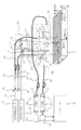
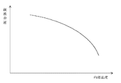
以下に本発明の一実施形態について図面を参照して説明する。図1は本発明の一実施形態である残留応力分布測定装置の概略構成図、図2はある鋼材についての内部温度と縦波音速との関係を示すグラフである。
【0020】
本実施形態の残留応力分布測定装置は、測定対象物の内部の残留応力分布を非接触で測定するものである。ここで、測定対象物としては、例えば、製鉄所において、熱間プロセスにより製造される板状の鋼材(厚板)を想定している。かかる厚板の表面温度は、通常、700℃ぐらいである。特に、本実施形態では、厚板をその厚さ方向に沿って複数の層に区分して考え、所定の測定位置において各層の残留応力を算出することにより、厚板の内部残留応力分布を求めることにする。
【0021】
残留応力は、音速比法を利用した次式から求めることができる。すなわち、音速比をR、厚板の圧延方向(縦幅方向)の応力をσ1、厚板の幅方向(横幅方向)の応力をσ2とすると、
R≡2VL/(VS1−VS2)
=R0+CR・(σ1+σ2)+F・(T−T0)
である。ここで、VLは縦波超音波の音速、VS1は厚板の圧延方向に変位した横波超音波の音速、VS2は厚板の幅方向に変位した横波超音波の音速である。また、R0は無応力時かつ室温T0時の音速比、CRは音弾性定数である。音速比R0、音弾性定数CR、及び無応力時のパラメータFは、予めサンプル(鋼材試験片)で測定しておく。したがって、厚板の各層を伝播する音速VL,VS1,VS2と、各層の内部温度Tとが得られれば、それらを上式に代入することにより、各層における残留応力σ1+σ2を算出することができる。
【0022】
ところで、よく知られているように、各種の鋼材では、その内部温度とその内部を伝播する縦波の音速との間に密接な関係がある。図2にある鋼材についての内部温度と縦波の音速との関係の一例を示す。図2において、横軸は鋼材の内部温度、縦軸は縦波の音速である。このグラフから、縦波の音速が遅いほど、鋼材の内部温度は高いという傾向があることが分かる。本実施形態の残留応力分布測定装置では、厚板の各層における縦波の速度を求めた後、図2に示すような内部温度と縦波音速との関係を利用して、厚板の内部温度を求めることにする。このとき、厚板の各層における縦波の音速はレーザ超音波法を用いて算出する。
【0023】
本実施形態の残留応力分布測定装置は、図1に示すように、超音波発生用レーザ10と、第一超音波発生部20a及び第二超音波発生部20bと、超音波検出用レーザ30と、第一ビーム取得部40a及び第二ビーム取得部40bと、第一ファブリ・ペロー干渉計50a及び第二ファブリ・ペロー干渉計50bと、第一光検出器60a及び第二光検出器60bと、コンピュータ70とを備える。また、この残留応力分布測定装置には、光学部品として、ビームスプリッタ81,82、ミラー84、集光レンズ86,87,88,89、光ファイバ91,92,93,94等が設けられている。
【0024】
超音波発生用レーザ10は、測定対象物2内に超音波を励起させるためのレーザである。超音波発生用レーザ10としては、例えばYAGレーザやCO2レーザなどの高エネルギーパルスレーザを使用する。以下では、この超音波発生用レーザ10から発せられたレーザビームの周波数をf1、その波長をλ1とする。
【0025】
超音波発生用レーザ10から発せられたレーザビームは、ビームスプリッタ81によって、二つのレーザビームに分岐させられる。その分岐した一方のレーザビームは第一超音波発生部20aに入射し、もう一方のレーザビームは第二超音波発生部20bに入射する。
【0026】
各超音波発生部20a,20bは、干渉縞走査法を用いて、測定対象物2の内部に、その表面に対して斜めに進行する超音波を発生させるものであり、請求項1又は8記載の発明における「超音波発生手段」に対応する。各超音波発生部20a,20bは、ビームスプリッタ21と、ミラー22と、音響光学素子23とを有する。
【0027】
各超音波発生部20a,20bに導かれたレーザビームは、ビームスプリッタ21によって、ビームスプリッタ21で反射される第一レーザビームL1と、ビームスプリッタ21を透過する第二レーザビームL2とに分けられる。第一レーザビームL1はそのまま測定対象物2の表面に入射する。一方、第二レーザビームL2は、ミラー22で反射された後、音響光学素子23に入射する。
【0028】
音響光学素子23は、音響光学効果(acousto−optic effect)を利用した素子であり、ここでは、周波数シフタとして利用する。音響光学素子23に適当な周波数の電気信号を与えると、音響光学素子23の内部に設けられた媒体が超音波振動を行い、弾性歪みや圧力が場所によって変化する。これにより、その媒体には屈折率変動が生じ、外部からの光がこの屈折率の変動領域に入射すると、その光は回折を起こす。このとき、その回折した光は超音波振動に起因するドップラーシフトを受け、一次回折光の周波数は、元の入射光の周波数から超音波の周波数分だけシフトした値となる。したがって、音響光学素子23から出射される第二レーザビームL2の周波数は、元の周波数f1からシフトする。こうして周波数がシフトした第二レーザビームL2は、測定対象物2の表面に入射する。ここで、周波数がシフトした第二レーザビームL2の周波数をf2とする。
【0029】
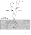
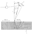
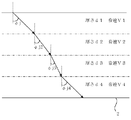
次に、干渉縞走査法について説明する。図3は干渉縞走査法の原理を説明するための図、図4は本実施形態の残留応力分布測定装置における各超音波発生部20a,20bの具体的な構成を説明するための図である。
【0030】
ここでは、図3に示すように、ビームスプリッタ21で反射した第一レーザビームL1は、測定対象物2の厚さ方向(測定対象物表面の法線方向)に対して角度(入射角度)θをもって測定対象物2に入射するものとする。一方、音響光学素子23から出射された第二レーザビームL2は、第一レーザビームL1とは反対側から、測定対象物2の厚さ方向に対して角度(入射角度)θをもって、第一レーザビームL1の照射位置と同一の照射位置に入射するものとする。すなわち、第一レーザビームL1と第二レーザビームL2とは互いに角度2θをなして測定対象物2上の同じ位置に照射される。以下では、かかる第一レーザビームL1と第二レーザビームL2が照射される測定対象物2上の位置を「超音波発生位置」又は単に「発生位置」と称する。また、第一超音波発生部20aでは、第一レーザビームL1と第二レーザビームL2とは、測定対象物2の幅方向に垂直な同一平面内にあり、一方、第二超音波発生部20bでは、第一レーザビームL1と第二レーザビームL2とは、測定対象物2の圧延方向に垂直な同一平面内にあるものとする。
【0031】
このような状況で、ビームスプリッタ21で反射した第一レーザビームL1と音響光学素子23から出射された第二レーザビームL2とが測定対象物2上の同一位置(超音波発生位置)に照射されると、二つのビームは干渉しあい、光波が強め合うところと弱め合うところが交互に現れる干渉縞を生じる。しかも、二つのレーザビームL1,L2の光周波数がわずかに異なることから、この干渉縞は測定対象物2の表面上を移動する。ここで、干渉縞の移動方向は、第一超音波発生部20aが発生させた場合は測定対象物2の圧延方向であり、第二超音波発生部20bが発生させた場合は測定対象物2の幅方向である。また、干渉縞の走査速度VR、干渉縞の波長λacoは、
VR=λ1・(f2−f1)/2sinθ
λaco=λ1/2sinθ
で与えられる。
【0032】
干渉によって生じる干渉縞は熱応力のパターンに対応するので、このパターンに応じた超音波が発生する。この超音波の波長は、干渉縞の波長λacoと同じである。特に、干渉縞の走査速度VRを測定対象物2の内部における超音波の音速よりも大きくすることによって、測定対象物2の表面に対して斜めに進行する超音波を発生させることができる。このとき、縦波超音波と横波超音波が同時に発生する。かかる超音波は、第一超音波発生部20aが発生させた場合は、測定対象物2の幅方向に垂直な平面内を進行し、第二超音波発生部20bが発生させた場合は、測定対象物2の圧延方向に垂直な平面内を進行する。第一超音波発生部20aが発生させた横波超音波は、圧延方向に変位した横波であり、一方、第二超音波発生部20bが発生させた横波超音波は、幅方向に変位した横波である。また、本実施形態では、縦波超音波については、第一超音波発生部20aが発生させたものだけを考え、第二超音波発生部20bが発生させたものは考えないことにする。すなわち、本実施形態では、超音波として、第一超音波発生部20aが発生させた縦波、第一超音波発生部20aが発生させた圧延方向変位横波、そして、第二超音波発生部20bが発生させた幅方向変位横波の三つを考える。また、第一超音波発生部20aが発生させた縦波の音速をVL、圧延方向変位横波の音速をVS1、幅方向変位横波の音速をVS2とする。
【0033】
かかる超音波についてその発生時の進行方向角度(測定対象物2の厚さ方向に対する角度)をφ、そのときの測定対象物2の内部における超音波の音速をVCとすると、
φ=sin−1(VC/VR)
という関係がある。したがって、干渉縞の走査速度VR、すなわち、入射角度θあるいは周波数差f2−f1を調整することによって、超音波の発生時における進行方向角度φを制御することができる。但し、超音波の音速VCは温度依存性があるため、表面温度を計測し、予め計測していた温度と音速との関係のデータに基づいてVCを決める。
【0034】
ところで、後に詳述するが、測定対象物2の各層における超音波の音速を求めるには、その超音波の発生時の進行方向角度を層の数と同じ数だけ予め設定しておき、その設定した各進行方向角度に当該超音波を発生させる度に、各進行方向角度に発生した当該超音波が測定対象物2の底面で反射して再び表面に戻ってくるまでの伝播時間を測定する必要がある。このため、超音波の発生時の進行方向角度φを制御する必要があるが、本実施形態では、かかる制御を、レーザビームの入射角度θを調整することによって行うことにする。具体的には、入射角度θの調整を容易に行えるようにするために、各超音波発生部20a,20bを、図4に示すような構成としている。すなわち、ビームスプリッタ21で反射された第一レーザビームL1を測定対象物2の表面に垂直に入射させることにする。また、音響光学素子23から出射された第二レーザビームL2を反射し、測定対象物2に照射するためのミラー24を設ける。そして、リニアステージ等を用いて、このミラー24の位置を、第一超音波発生部20aにおいては測定対象物2の圧延方向に沿って、第二超音波発生部20bにおいては測定対象物2の幅方向に沿って移動させることにより、第二レーザビームL2の入射角度の制御を行う。ここで、図4では、第二レーザビームL2の実際の入射角度は2θであるが、本実施形態では、その半分の角度θのことも入射角度と称することにする。
【0035】
尚、当然のことではあるが、超音波発生時の進行方向角度φについての制御は、第二レーザビームL2の代わりに第一レーザビームL1の入射角度を調整することにより、あるいは、第一レーザビームL1及び第二レーザビームL2の両方の入射角度を調整することにより、行うようにしてもよい。
【0036】
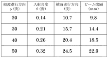
図5に、縦波の発生時の進行方向角度φを20度、30度、40度、50度に制御する場合の入射角度θの設定値の一例を示す。この例では、周波数差f2−f1を80MHzとしている。図5に示すように、縦波の発生時の進行方向角度φを20度にするには入射角度θを0.14度に設定すればよい。また、縦波の発生時の進行方向角度φを30度にするには入射角度θを0.21度に、その発生時の進行方向角度φを40度にするには入射角度θを0.26度に設定すればよい。そして、縦波の発生時の進行方向角度φを50度にするには入射角度θを0.32度に設定すればよい。
【0037】
この例から分かるように、入射角度θの設定値はとても小さいので、通常は、測定対象物2の表面からある程度遠く離れた位置、例えば4m離れた位置に、ミラー24を設置することにしている。図5の表に示した「ビーム間隔」とは、測定対象物2の表面から4m離れた高さ位置において測った、第一レーザビームL1と第二レーザビームL2との間隔のことである。具体的に、縦波の発生時の進行方向角度φを20度にするにはビーム間隔を9.8mmに設定すればよい。また、縦波の発生時の進行方向角度φを30度にするにはビーム間隔を14.4mmに、その発生時の進行方向角度φを40度にするにはビーム間隔を18.5mmに設定すればよい。そして、縦波の発生時の進行方向角度φを50度にするにはビーム間隔を22.0mmに設定すればよい。
【0038】
尚、縦波と同時に横波も発生するので、図5には、その縦波と同時に発生した横波の進行方向角度も示している。縦波と横波の進行方向が異なるのは、測定対象物2の内部における縦波の音速と横波の音速とが相違するからである。
【0039】
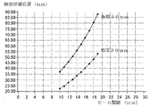
また、超音波が測定対象物2の内部を伝播し、その底面で反射して再び表面に戻ってくる位置(以下では、「超音波検出位置」又は単に「検出位置」という。)は、おおよそ予測することができる。一例として、図6にビーム間隔と縦波の検出候補位置との関係を示す。ここで、横軸は、測定対象物2の表面から4m離れた高さ位置におけるビーム間隔であり、縦軸は、レーザビームL1,L2の入射位置から圧延方向に沿って測った、縦波の検出候補位置である。かかる検出候補位置は、測定対象物2の厚さに依存するので、図6では、例として、測定対象物2の板厚が30mm、50mmである場合を示している。ところで、この図6のグラフは、縦波の進行方向が測定対象物2の内部で一定であると仮定して求めたものである。しかしながら、実際には、測定対象物2の内部温度は場所によって異なり、超音波の音速も一定ではないので、超音波の進行方向は、測定対象物2の内部で変化する。このため、図6のグラフを利用して求めた縦波の検出候補位置は、実際の検出位置とは異なる。このような理由から、図6では、検出位置ではなく、「検出候補位置」という表現を使っている。本実施形態では、かかる図6に示すようなビーム間隔と検出候補位置との関係を、実際の超音波の検出位置を得るための参考として利用する。具体的には、まず、図6のようなグラフを利用して、超音波の検出候補位置を見い出す。次に、実際に超音波を発生させることにより、その検出候補位置の周辺領域において、測定対象物2内を伝播してきた超音波の強度を検出する。そして、最も大きな強度位置を、実際の超音波の検出位置として決定する。
【0040】
また、各超音波発生部20a,20bは一体的に構成されており、測定対象物2の表面に平行な面上において測定対象物2の圧延方向及び幅方向に沿って移動することができる。各超音波発生部20a,20bの位置情報はコンピュータ70により認識されており、コンピュータ70は各超音波発生部20a,20bの位置情報に基づいて各超音波発生部20a,20bにおける超音波発生位置を知ることができる。
【0041】
超音波検出用レーザ30は、超音波発生用レーザ10からのレーザビームの照射によって測定対象物2内に発生し、測定対象物2内を伝播してきた超音波を検出するためのレーザである。超音波検出用レーザ30としては、単一周波数のレーザビームを発するものを用いる。
【0042】
超音波検出用レーザ30から発せられたレーザビーム(第三レーザビーム)L3は、ビームスプリッタ82によって、二つの第三レーザビームL3に分岐させられる。その分岐した一方の第三レーザビームL3は、集光レンズ86で集光された後、光ファイバ91に入射する。この光ファイバ91は、当該第三レーザビームL3を第一ビーム取得部40aに導くものである。また、ビームスプリッタ82で分岐したもう一方の第三レーザビームL3は、ミラー84で反射し、集光レンズ87で集光された後、光ファイバ92に入射する。この光ファイバ92は、当該第三レーザビームL3を第二ビーム取得部40bに導くものである。
【0043】
各ビーム取得部40a,40bは、第三レーザビームL3を所定の超音波検出位置に導くと共に、測定対象物2の表面で反射・散乱した第三レーザビームL3を取得するものであり、図1に示すように、二つの集光レンズ41,42と、ハーフミラー43とを有する。特に、第一ビーム取得部40aは、第三レーザビームL3を、第一超音波発生部20aによって発生された縦波又は横波の検出位置に導き、第二ビーム取得部40bは、第三レーザビームL3を、第一超音波発生部20bによって発生された横波の検出位置に導く。各ビーム取得部40a,40bは、請求項1記載の発明における「ビーム取得手段」に対応する。
【0044】
また、各ビーム取得部40a,40bは一体的に構成されており、測定対象物2の表面に平行な面上において測定対象物2の圧延方向及び幅方向に沿って移動することができる。各ビーム取得部40a,40bの位置情報はコンピュータ70により認識されており、コンピュータ70は各ビーム取得部40a,40bの位置情報に基づいて各ビーム取得部40a,40bにおける超音波検出位置を知ることができる。
【0045】
各ビーム取得部40a,40bに入射した第三レーザビームL3は、集光レンズ41で集光され、ハーフミラー43を透過した後、測定対象物2上の所定の超音波検出位置に照射される。測定対象物2の表面は粗面であるため、かかる第三レーザビームL3は測定対象物2の表面においてほぼ等方的に散乱される。このとき、当該検出位置に、測定対象物2の内部を伝播してきた超音波が戻ってくると、当該検出位置が超音波振動をする。これにより、測定対象物2の表面で散乱された第三レーザビームL3は、測定対象物2の表面の超音波振動に起因するドップラーシフトを受けて周波数が変化する。
【0046】
測定対象物2の表面で散乱された第三レーザビームL3のうち、その一部は、ハーフミラー43で反射された後、集光レンズ42で集光される。第一ビーム取得部40aの集光レンズ42で集光された第三レーザビームL3は、光ファイバ93に入射する。この光ファイバ93は、かかる第三レーザビームL3を第一ファブリ・ペロー干渉計50aに導くものである。光ファイバ93から出射した第三レーザビームL3は、集光レンズ88で集光された後、第一ファブリ・ペロー干渉計50aに入射する。一方、第二ビーム取得部40bの集光レンズ42で集光された第三レーザビームL3は、光ファイバ94に入射する。この光ファイバ94は、かかる第三レーザビームL3を第二ファブリ・ペロー干渉計50bに導くものである。光ファイバ94から出射した第三レーザビームL3は、集光レンズ89で集光された後、第二ファブリ・ペロー干渉計50bに入射する。
【0047】
各ファブリ・ペロー干渉計50a,50bは、超音波振動に起因して生じる第三レーザビームL3の周波数変化を検出するものであり、互いに対向する二つの反射ミラー51,52を有する。この二つの反射ミラー51,52は共振器を構成し、第三レーザビームL3を二つの反射ミラー51,52の間で多重反射させることによりバンドパスフィルタとして機能する。二つの反射ミラー51,52間の距離を調節することにより、この共振器を透過する光の周波数を調節することができる。各ファブリ・ペロー干渉計は、請求項1記載の発明における「周波数変化検出手段」に対応する。
【0048】
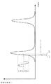
ここで、ファブリ・ペロー干渉計50a,50bにおける共振曲線について説明する。図7はこの共振曲線の一例を示す図である。図7において、横軸は入射する光の周波数fを、縦軸はファブリ・ペロー干渉計50a,50bからの出力、すなわちファブリ・ペロー干渉計50a,50bを透過する光の強度Iを示している。図7から分かるように、透過光強度Iは、特定の周波数において急峻なピークを示すが、ピークの前後では速やかに低下する。このピークを示す周波数は、ファブリ・ペロー干渉計50a,50bの反射ミラー51,52間の距離を調節することによって変えることができる。そこで、図7に示す曲線の傾きが最大となる点(共振曲線動作点)Aにおける周波数が、ちょうど第三レーザビームL3の発振周波数と一致するように反射ミラー51,52間の距離が調節されていれば、周波数のわずかな変化±Δfを、相対的に大きな透過光強度の変化±ΔIに変換することができる。これにより、ファブリ・ペロー干渉計50a,50bは、測定対象物2の表面の超音波振動に起因するドップラーシフトを受けて周波数が変化した第三レーザビームL3が入力したときに、その周波数の変化を透過光強度の変化として出力する。
【0049】
第一ファブリ・ペロー干渉計50aから出力された透過光強度は、第一光検出器60aに送られ、一方、第二ファブリ・ペロー干渉計50bから出力された透過光強度は、第二光検出器60bに送られる。各光検出器60a,60bは、透過光強度を電気信号に変換するものである。これにより、超音波振動は、最終的に電気的な信号として捉えられる。各光検出器60a,60bからの信号は、コンピュータ70に送られ、波形データとして記録される。
【0050】
尚、本実施形態では、請求項8記載の発明における「超音波検出手段」として、第一ビーム取得部40a、第一ファブリ・ペロー干渉計50a及び第一光検出器60aと、第二ビーム取得部40b、第二ファブリ・ペロー干渉計50b及び第二光検出器60bとが対応する。
【0051】
コンピュータ70は、かかる波形データに基づいて、超音波が測定対象物2の内部を伝播し、その底面で反射して再び表面に戻ってくるまでの伝播時間を求める。超音波発生用レーザ10からレーザビームが発せられたタイミングと、かかるレーザビームが測定対象物2に照射するタイミングとは予め分かっている。このため、コンピュータ70は、各光検出器60a,60bから送られた波形データに基づいて、周波数変化を検出したタイミングを調べることにより、超音波の伝播時間を求めることができる。また、コンピュータ70は、縦波、圧延方向変位横波の各々について、超音波発生部20aの位置情報とビーム取得部40aの位置情報とに基づいて発生位置と検出位置との間の水平距離を求めると共に、幅方向変位横波について、超音波発生部20bの位置情報とビーム取得部40bの位置情報とに基づいて発生位置と検出位置との間の水平距離を求める。すなわち、コンピュータ70は、請求項1又は8記載の発明における「演算手段」及び「距離算出手段」に対応する。
【0052】
本実施形態では、縦波、圧延方向変位横波、幅方向変位横波の各超音波について、その発生時の進行方向角度を測定対象物2の層の数と同じ数だけ予め設定しておき、コンピュータ70は、各超音波について、第一又は第二の超音波発生部20a,20bが各進行方向角度に超音波を発生させる度に、当該進行方向に発生した超音波の伝播時間及び水平距離を求める。すなわち、縦波、圧延方向変位横波、幅方向変位横波の各超音波について、その発生時の進行方向角度を制御して、上記の伝播時間の測定処理と水平距離の算出処理とを所定回数だけ繰り返す。その後、コンピュータ70は、各超音波について、各進行方向角度に発生した超音波の伝播時間と、各進行方向に発生した超音波についての発生位置と検出位置との間の水平距離とに基づいて、測定対象物2の各層における超音波の音速を算出する。
【0053】
また、コンピュータ70は、その算出した各層における縦波の音速に基づいて測定対象物2の各層における内部温度を求める。ここで、コンピュータ70には、各種の鋼材についての内部温度と縦波音速との対応関係を示すデータベースが構築されている。このため、コンピュータ70は、そのデータベースを利用して、測定対象物2の各層における縦波の音速から各層の内部温度を容易に求めることができる。
【0054】
次に、各進行方向角度に発生した超音波の伝播時間及び水平距離から測定対象物2の各層における超音波の音速を算出する方法について詳しく説明する。図8及び図9は測定対象物2の各層における超音波の音速を算出する方法を説明するための図である。
【0055】
熱間プロセスで製造される厚板の場合、その内部温度は場所によって異なり、超音波の音速も一定ではない。このため、超音波の進行方向は厚板の内部で変化する。本実施形態では、第一又は第二の超音波発生部20a,20bによって発生された超音波の伝播領域に対応する測定対象物2の領域においては、超音波の音速が測定対象物2の各層内で一定であると仮定する。この場合、測定対象物2の各層の厚さを小さく設定すればするほど、その仮定した超音波の音速は実際の値に近似する。したがって、各層の厚さを十分小さく設定すれば、内部温度や残留応力を高い精度で測定することが可能である。
【0056】
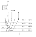
いま、図8及び図9に示すように、測定対象物2である厚板をその厚さ方向に沿って四つの層に区分した場合を考えることにする。これら各層を、厚板の表面側から順番に、第1層、第2層、第3層、第4層と称する。ここで、第k層(k=1,2,3,4)における厚さをdk、そこでの超音波の平均音速をVkとする。そして、超音波の発生時における進行方向角度がφj(j=1,2,3,4)のとき、当該超音波の伝播時間をtjとする。
【0057】
また、上記の仮定の下では、各層における超音波の進行方向は一定であるので、図9に示すように、超音波は各層の境界面を通過する際に屈折すると考える必要がある。但し、図8では、かかる屈折を省略し、超音波の伝播経路を直線で示している。ここで、図9に示すように、超音波が測定対象物2の第1層を進行方向角度φj(j=1,2,3,4)で伝播したとき、第1層と第2層の境界面における屈折角度をφj2、第2層と第3層の境界面における屈折角度をφj3、第3層と第4層の境界面における屈折角度をφj4とする。
【0058】
超音波が測定対象物2の第1層を進行方向角度φj(j=1,2,3,4)で伝播した場合、当該超音波の伝播時間tjは、
tj=2[d1/(V1・cosφj)+d2/(V2・cosφj2)+d3/(V3・cosφj3)+d4/(V4・cosφj4)]
である。ここで、各境界面においてスネルの法則を適用すると、
cosφjm={1−(Vm/V1)2(1−cos2φj)}1/2
≡F(V1,Vm,cosφj)
と表すことができる。ただし、m=2,3,4である。したがって、
tj=2[d1/(V1・cosφj)
+d2/(V2・F(V1,V2,cosφj))
+d3/(V3・F(V1,V3,cosφj))
+d4/(V4・F(V1,V4,cosφj)]
となる。ここで、j=1,2,3,4である。
【0059】
かかる四つの伝播時間t1,t2,t3,t4の式において、当該超音波の発生時の進行方向角度φ1,φ2,φ3,φ4は干渉縞走査法により既知のパラメータであり、各層の厚さd1,d2,d3,d4も予め分かっている。したがって、コンピュータ70は、レーザ超音波法を利用して求めた当該超音波についての伝播時間t1,t2,t3,t4を、上記の各式に代入し、当該超音波の音速V1,V2,V3,V4を未知数とする非線形連立方程式を解くことにより、各層における当該超音波の音速V1,V2,V3,V4を算出する。
【0060】
ここで、解くべき連立方程式は非線形であるので、その解は一意的でなく、各層における当該超音波の音速V1,V2,V3,V4として複数組の解が得られる。このため、コンピュータ70は、各進行方向角度φj(j=1,2,3,4)に発生した当該超音波についての発生位置と検出位置との間の水平距離xjを表す式を、複数組の解のうちから適切な一の組の解を選択するための判定式として利用する。水平距離xj(j=1,2,3,4)を表す式は、
xj=2[d1・tanφj+d2・tanφj2+d3・tanφj3+d4・tanφj4]
で与えられる。ここで、スネルの法則により、
tanφjm=(Vm/V1)(1−cos2φj)1/2×{1−(Vm/V1)2(1−cos2φj)}−1/2
である。ただし、m=2,3,4である。コンピュータ70は、まず、かかる四つの水平距離を表す式に、超音波発生部の位置情報及びビーム取得部の位置情報に基づいて求めた当該超音波の水平距離x1,x2,x3,x4を代入する。次に、これらの式に、四つの伝播時間t1,t2,t3,t4の式を解いて得られた各組の解を代入して、四つの水平距離を表す式が満たされるか否かを判定する。そして、四つの水平距離を表す式を満たす一組の解を、各層における当該超音波の音速V1,V2,V3,V4として決定する。
【0061】
実際には、コンピュータ70は、専用の非線形回帰計算ソフトを用いて、各層における超音波の音速を求める。かかる専用の非線形回帰計算ソフトとしては、例えば、Levenberg−Marquardtアルゴリズムモジュールを用いて作成したものを使用することができる。
【0062】
このようにして、縦波、圧延方向変位横波、幅方向変位横波の各々について、測定対象物2の各層における当該超音波の音速を算出することにより、測定対象物2の内部での音速分布を得ることができる。また、各層における縦波の音速に基づいて各層の内部温度を得ることができる。したがって、コンピュータ70は、各層における内部温度と各層における各超音波の音速を、音速比法を利用した式に代入して計算することにより、当該超音波照射位置近傍での各層の残留応力を求めることができる。
【0063】
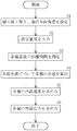
次に、本実施形態の残留応力分布測定装置において、測定対象物2の残留応力分布を測定する手順について説明する。図10はその残留応力分布測定装置において測定対象物2の残留応力分布を測定する手順を説明するためのフローチャートである。
【0064】
まず、オペレータは、測定対象物2をその厚さ方向に沿って区分する層の数、各層の厚さを設定すると共に、干渉縞走査法により発生させる縦波、圧延方向変位横波、幅方向変位横波の各々について、その進行方向角度を層の数と同数だけ設定する(S1)。そして、オペレータは、これらの設定値や計算に必要なパラメータ値をコンピュータ70に入力する(S2)。
【0065】
次に、縦波、圧延方向変位横波、幅方向変位横波の各超音波について伝播時間を測定する(S3)。本実施形態では、超音波発生部とビーム取得部を二組設けたことにより、二つの超音波についての伝播時間の測定処理を同時に行うことができる。例えば、縦波の伝播時間と幅方向変位横波の伝播時間を同時に測定し、その後に、圧延方向変位横波の伝播時間を測定することにする。
【0066】
具体的には、まず、オペレータは、縦波についてステップS1で設定した複数の進行方向角度のうち、一の進行方向角度を選択すると共に、幅方向変位横波についても一の進行方向角度を選択する。そして、その選択した縦波の進行方向角度に縦波が発生するように、第一超音波発生部20aにおけるミラー24の位置を調節し、また、その選択した横波の進行方向角度に横波が発生するように、第二超音波発生部20bにおけるミラー24の位置を調節する。その後、図6に示すようなビーム間隔と検出候補位置との関係を参考にして、実際に、超音波発生用レーザ10からレーザビームを発することにより、第一超音波発生部20aによって発生された縦波の実際の検出位置と、第二超音波発生部20bによって発生された横波の実際の検出位置とを検出する。そして、超音波検出用レーザ30から発せられた第三レーザビームL3が当該縦波の検出位置に照射されるように、第一ビーム取得部40aの位置を調整すると共に、第三レーザビームL3が当該横波の検出位置に照射されるように、第二ビーム取得部40bの位置を調整する。
【0067】
こうして位置調整がされた後、コンピュータ70は、第一超音波発生部20aの位置情報と第一ビーム取得部40aの位置情報とに基づいて、当該選択した進行方向に発生する縦波についての発生位置と検出位置との間の水平距離を求める。また、第二超音波発生部20bの位置情報と第二ビーム取得部40bの位置情報とに基づいて、当該選択した進行方向角度に発生する幅方向変位横波についての発生位置と検出位置との間の水平距離を求める。これらの水平距離はコンピュータ70の所定のメモリに記憶される。
【0068】
こうして準備が整うと、次に、超音波発生用レーザ10からレーザビームを発することにより測定対象物2の内部に超音波を発生させると共に、超音波検出用レーザ30から第三レーザビームを発する。これにより、第一ビーム取得部40a及び第一ファブリ・ペロー干渉計50aは、縦波の超音波の振動に起因して生じる第三レーザビームの周波数変化を検出し、第二ビーム取得部40b及び第二ファブリ・ペロー干渉計50bは、幅方向変位横波の超音波の振動に起因して生じる第三レーザビームの周波数変化を検出する。そして、コンピュータ70は、それらの周波数変化を表す波形データに基づいて、縦波の伝播時間と幅方向変位横波の伝播時間とを求める。これらの伝播時間はコンピュータ70の所定のメモリに記憶される。
【0069】
次に、ステップS1において設定したすべての進行方向角度に対して、上記の処理を繰り返すことにより、各進行方向角度に発生した縦波の伝播時間、各進行方向に発生した縦波についての発生位置と検出位置との間の水平距離、各進行方向に発生した幅方向変位横波の伝播時間、各進行方向に発生した幅方向変位横波についての発生位置と検出位置との間の水平距離が得られる。
【0070】
その後、同様にして、第一超音波発生部20a、第一ビーム取得部40a及び第一ファブリ・ペロー干渉計50aを用いて、各進行方向角度に発生した圧延方向変位横波についての発生位置と検出位置との間の水平距離を求めると共に、各進行方向角度に発生した圧延方向変位横波の伝播時間を測定する。こうして、縦波、圧延方向変位横波、幅方向変位横波の各超音波について、当該超音波を各進行方向角度に発生させたときの水平距離と伝播時間とが得られる。
【0071】
次に、コンピュータ70は、各進行方向角度に発生した各超音波の伝播時間と各進行方向角度に発生した各超音波についての発生位置と検出位置との間の水平距離とに基づいて、測定対象物2の各層における縦波の音速、圧延方向変位横波の音速、幅方向変位横波の音速を算出する(S4)。その後、コンピュータ70は、当該測定対象物2についての内部温度と縦波音速との対応関係を示すデータベースを利用し、測定対象物2の各層における縦波の音速から各層の内部温度を求める(S5)。そして、コンピュータ70は、各層における内部温度と各超音波の音速を、音速比法を利用した式に代入して計算することにより、超音波照射位置近傍での各層における残留応力(圧延方向の応力と幅方向の応力との和)を求める。こうして得られた各層の残留応力は、例えば、コンピュータ70の画面に表示される。
【0072】
次に、本発明者等は、本実施形態の残留応力分布測定装置を用いて各層における超音波の音速が十分な精度で求められるかどうかを検証した。この検証は、次のようにして行われた。まず、各層の内部温度を仮定する。そして、その仮定した各層の内部温度から、内部温度と超音波(ここでは縦波とする。)の音速との対応関係を示すデータベースを利用して各層における超音波の音速を求める。その後、これら各層における超音波の音速を用いて、各進行方向角度に発生する超音波についての伝播時間のデータと水平距離のデータとを作成する。次に、その作成した伝播時間のデータと水平距離のデータとをコンピュータ70にインプットする。コンピュータ70は専用の非線形回帰計算ソフトを用いて各層における超音波の音速を算出する。そして、こうして算出された各層における超音波の音速が、最初に仮定した内部温度から求められる超音波の音速と一致するかどうかを調べた。
【0073】
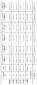
図11は各層における超音波の音速を算出する方法を検証する際に作成した各種のデータの一例を示す図である。本検証においては、層の数を6とし、各層の厚さをすべて5mmと仮定した。そして、図11に示すように、第1層の内部温度を775℃、第2層の内部温度を790度、第3層の内部温度を830℃、第4層の内部温度を810℃、第5層の内部温度を850℃、第6層の内部温度を770℃と仮定した。また、超音波が第1層を伝播する進行方向角度φj(j=1,2,・・・ ,6)をそれぞれ、15度、20度、25度、30度、35度、40度と仮定した。
【0074】
このような各種のデータを仮定した後、まず、内部温度と超音波の音速との対応関係を示すデータベースを用いて、上記の仮定した各層の内部温度から各層における超音波の音速を求めた。具体的には、図11に示すように、第1層における超音波の音速は6008.38m/sec、第2層における超音波の音速は5864.15m/sec、第3層における超音波の音速は5479.55m/sec、第4層における超音波の音速は5671.85m/sec、第5層における超音波の音速は5287.25m/sec、第6層における超音波の音速は6056.45m/secである。
【0075】
次に、これら各層における超音波の音速を用いて、進行方向角度がφj(j=1,2,・・・ ,6)である場合に超音波が各層を伝播するのに要する時間(各層における伝播時間)を求めた。かかる各層における伝播時間は図11に示されている。その後、各進行方向角度φj(j=1,2,・・・ ,6)に発生した超音波の(トータルの)伝播時間と、発生位置と検出位置との間の水平距離とを求めた。図11に示すように、進行方向角度がφ1である場合は、超音波の伝播時間が1.083×10⁻⁵sec、発生位置と検出位置との間の水平距離が1.5280×10⁻²mである。進行方向角度がφ2である場合は、超音波の伝播時間が1.111×10⁻⁵sec、発生位置と検出位置との間の水平距離が2.0704×10⁻²mである。進行方向角度がφ3である場合は、超音波の伝播時間が1.147×10⁻⁵sec、発生位置と検出位置との間の水平距離が2.6433×10⁻²mである。進行方向角度がφ4である場合は、超音波の伝播時間が1.194×10⁻⁵sec、発生位置と検出位置との間の水平距離が3.2577×10⁻²mである。進行方向角度がφ5である場合は、超音波の伝播時間が1.254×10⁻⁵sec、発生位置と検出位置との間の水平距離が3.9269×10⁻²mである。進行方向角度がφ6である場合は、超音波の伝播時間が1.329×10⁻⁵sec、発生位置と検出位置との間の水平距離が4.6682×10⁻²mである。
【0076】
こうして、仮定した内部温度に基づいて、各進行方向角度φj(j=1,2,・・・ ,6)に発生した超音波の伝播時間のデータと、発生位置と検出位置との間の水平距離のデータとを求めた後、これらの超音波の伝播時間のデータと水平距離のデータとを測定値としてコンピュータ70にインプットした。そして、コンピュータ70は、専用の非線形回帰ソフトを用いて、各層における超音波の音速を演算した。本検証では、コンピュータ70で用いる非線形回帰ソフトとして、前述したLevenberg−Marquardtアルゴリズムモジュールを用いて作成したものを使用した。ここで、超音波発生時の進行方向角度がφj(j=1,2,・・・ ,6)のとき、回帰計算のFITTING評価式を、
Δj={(xjCAL−xjMES)/xjINIT}2+{(tjCAL−tjMES)/tjINIT}2とした。添字「CAL」は当該回帰計算における計算値を表す。また、添字「MES」は上記のインプットされた測定値を表し、添字「INIT」は当該回帰計算における初期値(暫定推定値)を表す。
【0077】
かかる演算の結果、第1層における超音波の音速として6.0097×10³m/sec、第2層における超音波の音速として5.8225×103m/sec、第3層における超音波の音速として5.5441×103m/sec、第4層における超音波の音速として5.6373×103m/sec、第5層における超音波の音速として5.2625×103m/sec、第6層における超音波の音速として6.0967×103m/secが得られた。
【0078】
この演算により得られた各層における超音波の音速(計算音速値)を、図11において最初に求めた各層における超音波の音速(仮定音速値)と比較すると、各層における計算音速値と仮定音速値との誤差は1%程度である。したがって、本実施形態の残留応力分布測定装置を用いることにより、各層における超音波の音速、したがって残留応力を十分な精度で求めることができる。
【0079】
本実施形態の残留応力分布測定装置では、レーザ超音波法及び干渉縞走査法を用いることにより、測定対象物の内部にその表面に対して斜めに進行する超音波を発生させ、縦波、圧延方向変位横波、幅方向変位横波の各超音波について、それを複数の進行方向の各々に発生させたときの伝播時間を求める。また、各進行方向に発生した当該超音波についての発生位置と検出位置との間の水平距離を求める。そして、各超音波について、その求めた複数の伝播時間及び水平距離に基づいて、厚さ方向に沿って予め区分された測定対象物の各層における音速を算出した後、各層における縦波の音速に基づいて各層の内部温度を求め、各超音波についての各層の音速、各層の内部温度に基づいて各層の残留応力を算出する。したがって、本実施形態の残留応力分布測定装置を用いると、測定対象物の残留応力分布を直接求めることができる。特に、レーザ超音波法及び干渉縞走査法を用いているので、熱間オンラインで測定対象物の残留応力分布を求めることができる。
【0080】
尚、本発明は上記の実施形態に限定されるものではなく、その要旨の範囲内において種々の変形が可能である。
【0081】
上記の実施形態では、縦波の音速に基づいて測定対象物の内部温度を求める場合について説明したが、横波の音速に基づいて測定対象物の内部温度を求めるようにしてもよい。この場合は、コンピュータに、各種の鋼材についての内部温度と横波の音速との対応関係のデータベースを構築しておく必要がある。
【0082】
また、上記の実施形態では、測定対象物をその厚さ方向に沿って四つの層に区分して各層の内部温度を測定する場合について説明したが、一般に、測定対象物を四つ以上の複数の層に区分して、各層の内部温度や残留応力を測定してもよい。特に、区分する層の数が多ければ多いほど、測定対象物の内部における温度分布や残留応力分布の測定精度が向上する。このため、かかる測定精度を考慮して、測定対象物を区分する層の数を決定する必要がある。
【0083】
また、上記の実施形態では、超音波発生部、ビーム取得部、ファブリ・ペロー干渉計及び光検出器を二組設けた場合について説明したが、それらの構成要素を一組だけ設けるようにしてもよい。この場合は、縦波、圧延方向変位横波、幅方向変位横波の各超音波についての伝播時間を個別に測定することになる。あるいは、かかる構成要素を三組設けるようにしてもよい。これにより、各超音波の伝播時間を一度に測定することができる。
【0084】
更に、上記の実施形態では、測定対象物として、熱間プロセスで製造される厚板を用いた場合について説明したが、本発明の残留応力分布測定装置は、かかる厚板以外のどのような物に対しても適用することができる。
【0085】
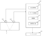
また、上記の実施形態では、レーザ超音波法を用いて、測定対象物の内部にその表面に対して斜めに進行する超音波を発生させ、測定対象物の底面で反射して再び表面に戻ってきた超音波を検出する場合について説明したが、例えば、探触子を用いて、超音波の発生・検出を行うことも可能である。図12は本発明の変形例である残留応力分布測定装置の概略構成図である。
【0086】
図12に示す残留応力分布測定装置は、第一の探触子110と、第二の探触子120と、探傷器130と、コンピュータ140とを備える。第一の探触子110は、測定対象物2の内部に、その表面に対して斜めに進行する超音波を発生させるものである。ここで、第一の探触子110は、縦波の超音波、測定対象物2の縦幅方向に変位した横波の超音波、測定対象物2の横幅方向に変位した横波の超音波を発生させる。第二の探触子120は、第一の探触子110が発生させた超音波の各々について、測定対象物2の底面で反射して再び表面に戻ってきた当該超音波を受信し、当該超音波の波形データを検出するものである。第一の探触子110及び第二の探触子120はそれぞれ、測定対象物2の表面上で移動することができる。二つの探触子110,120の移動はコンピュータ140により制御される。各探触子110,120の位置情報はコンピュータ140により認識されており、コンピュータ140は各探触子110,120の位置情報に基づいて超音波発生位置及び超音波検出位置を知ることができる。第一の探触子110は、請求項8記載の発明における「超音波発生手段」に対応し、第二の探触子120は、請求項8記載の発明における「超音波検出手段」に対応する。
【0087】
探傷器130は、発生制御部131と、データ処理部132と、記憶部133と、波形表示部134とを有する。発生制御部131は、第一の探触子110による超音波の発生を制御するものである。具体的には、超音波発生のタイミング、発生させる超音波についてエネルギーや波形を制御する。データ処理部132は、第二の探触子120が検出した超音波の波形データを増幅したり、ノイズを除去したりするものである。データ処理部132で処理された波形データは、記憶部133に記憶される。波形表示部134は、波形データを表示するものである。
【0088】
尚、探触子110,120及び探傷器130としては、市販のものを使用することができる。
【0089】
コンピュータ140は、上記の実施形態におけるコンピュータ70と同じ機能を有するものであり、請求項8記載の発明における「距離算出手段」及び「演算手段」に対応する。この変形例でも、測定対象物2をその厚さ方向に沿って複数の層に区分している。そして、縦波、縦幅方向変位横波、幅方向変位横波の各超音波について、測定対象物2の第1層における当該超音波の進行方向角度を測定対象物2の層の数と同じ数だけ予め設定している。コンピュータ140は、各超音波について、第一の探触子110が各進行方向角度に当該超音波を発生させる度に、当該進行方向角度に発生した超音波の伝播時間を求めると共に、当該進行方向角度に発生した超音波についての発生位置と検出位置との間の水平距離を求める。その後、コンピュータ140は、各超音波について、各進行方向角度に発生した当該超音波の伝播時間と、各進行方向角度に発生した当該超音波についての発生位置と検出位置との間の水平距離とに基づいて、測定対象物2の各層における超音波の音速を算出する。また、コンピュータ140は、その算出した各層における縦波の音速に基づいて測定対象物2の各層における内部温度を求め、各層における各超音波の音速及び各層の内部温度に基づいて各層における残留応力を算出する。
【0090】
尚、変形例の残留応力分布測定装置では、第1層における超音波の進行方向角度の算出方法が上記の実施形態のものと異なる。すなわち、第一の探触子110から発生した超音波は、第一の探触子110と測定対象物2との境界面で屈折して測定対象物2内に入る。このとき、第1層における超音波の進行方向角度(境界面での屈折角)は、境界面への超音波の入射角、測定対象物2の外部を伝播する超音波の音速、測定対象物2の表層を伝播する超音波の音速を用いて、スネルの法則より算出される。ここで、測定対象物2の表層を伝播する超音波の音速は、測定対象物2の表面温度を測定し、その測定した表面温度から求めることができる。
【0091】
かかる変形例の残留応力分布測定装置でも、上記の実施形態における残留応力分布測定装置と同様に、測定対象物の残留応力分布を直接測定することができる。但し、探触子を用いて超音波の発生、検出を行うので、変形例の残留応力分布測定装置は、熱間オンラインで測定対象物の残留応力分布を測定する場合に用いるには適さない。
【0092】
【発明の効果】
以上説明したように本発明の残留応力分布測定装置では、測定対象物の内部にその表面に対して斜めに進行する超音波を発生させ、縦波、縦幅方向変位横波、横幅方向変位横波の各超音波について、それを複数の進行方向の各々に発生させたときの伝播時間を求める。また、各進行方向に発生した当該超音波についての発生位置と検出位置との間の距離を求める。そして、各超音波について、その求めた複数の伝播時間及び発生位置と検出位置との間の距離に基づいて厚さ方向に沿って予め区分された測定対象物の各層における音速を算出した後、一の超音波についての各層の音速に基づいて各層の内部温度を求め、各超音波についての各層の音速、各層の内部温度に基づいて各層の残留応力を算出する。したがって、本発明の残留応力分布測定装置を用いると、測定対象物の残留応力分布を直接求めることができる。特に、レーザ超音波法及び干渉縞走査法を用いることにより、熱間オンラインで測定対象物の残留応力分布を求めることができる。
【0093】
また、本発明の残留応力分布測定方法によれば、上記と同様に、測定対象物の残留応力分布を直接求めることができる。特に、レーザ超音波法及び干渉縞走査法を用いることにより、熱間オンラインで測定対象物の残留応力分布を求めることができる。
【図面の簡単な説明】
【図1】本発明の一実施形態である残留応力分布測定装置の概略構成図である。
【図2】ある鋼材についての内部温度と縦波音速との関係を示すグラフである。
【図3】干渉縞走査法の原理を説明するための図である。
【図4】本実施形態の残留応力分布測定装置における各超音波発生部の具体的な構成を説明するための図である。
【図5】縦波の発生時の進行方向角度φを制御する場合のレーザビームの入射角度θの設定値の一例を示す図である。
【図6】ビーム間隔と縦波の検出候補位置との関係を示すグラフである。
【図7】本実施形態の残留応力分布測定装置におけるファブリ・ペロー干渉計の共振曲線の一例を示す図である。
【図8】測定対象物の各層における超音波の音速を算出する方法を説明するための図である。
【図9】測定対象物の各層における超音波の音速を算出する方法を説明するための図である。
【図10】本実施形態の残留応力分布測定装置において測定対象物の残留応力分布を測定する手順を説明するためのフローチャートである。
【図11】各層における超音波の音速を算出する方法を検証する際に作成した各種のデータの一例を示す図である。
【図12】本発明の変形例である残留応力分布測定装置の概略構成図である。
【符号の説明】
2 測定対象物
10 超音波発生用レーザ
20a 第一超音波発生部
20b 第二超音波発生部
21 ビームスプリッタ
22,24 ミラー
23 音響光学素子
30 超音波検出用レーザ
40a 第一ビーム取得部
40b 第二ビーム取得部
41,42 集光レンズ
43 ハーフミラー
50a 第一ファブリ・ペロー干渉計
50b 第二ファブリ・ペロー干渉計
51,52 反射ミラー
60a 第一光検出器
60b 第二光検出器
70 コンピュータ
81,82 ビームスプリッタ
84 ミラー
86,87,88,89 集光レンズ
91,92,93,94 光ファイバ
110 第一の探触子
120 第二の探触子
130 探傷器
131 発生制御部
132 データ処理部
133 記憶部
134 波形表示部
140 コンピュータ[0001]
TECHNICAL FIELD OF THE INVENTION
The present invention relates to a residual stress distribution measuring device and a residual stress distribution measuring method for measuring, for example, a residual stress distribution of a steel material.
[0002]
[Prior art]
In general, in a hot thick plate manufacturing process, a thick plate having desired specification characteristics is manufactured by controlling a rolling condition and a cooling condition of controlled rolling. Information that can be helpful in controlling such rolling and cooling conditions includes temperature information and residual stress information of the thick plate.
[0003]
Conventionally, regarding temperature information, the surface temperature of a thick plate is measured using a radiation thermometer or the like, and a model calculation such as a simulation is performed to estimate the internal temperature of the thick plate. On the other hand, regarding the residual stress information, the residual stress was measured only on the surface of the object to be measured using a contact ultrasonic probe or the like, or only the average value of the residual stress was measured in the thickness direction of the test piece ( For example, see Non-Patent
[0004]
[Non-patent document 1]
"Sound elasticity", published by the Non-Destructive Inspection Association, 1994, p. 94-107
[Patent Document 1]
JP-A-2000-301220
[0005]
[Problems to be solved by the invention]
As described above, conventionally, it has not been possible to directly measure the residual stress distribution of the measurement object. Conventionally, in the hot thick plate manufacturing process, rolling control in consideration of residual stress information is not actually performed. However, in the thick plate manufacturing process, there is a problem that the steel material warps due to the influence of the residual stress. For this reason, if information on the residual stress is obtained online hot, it is possible to perform better rolling control, such as performing control for reducing the residual stress.
[0006]
The present invention has been made based on the above circumstances, and an object of the present invention is to provide a residual stress distribution measuring device and a residual stress distribution measuring method capable of directly measuring a residual stress distribution of an object to be measured. .
[0007]
The present invention has been made based on the above circumstances, and an object of the present invention is to provide a residual stress distribution measuring device and a residual stress distribution measuring method capable of measuring a residual stress distribution of a measurement object hot online. Things.
[0008]
[Means for Solving the Problems]
In order to achieve the above object, the invention according to
[0009]
According to a second aspect of the present invention, in the residual stress distribution measuring apparatus according to the first aspect, the first laser beam and the second laser beam are two laser beams generated from one laser device. It is characterized by being obtained by branching and making one of the branched laser beams incident on the acousto-optic element.
[0010]
According to a third aspect of the present invention, in the residual stress distribution measuring device according to the first or second aspect, the ultrasonic wave generating means sets an incident angle of at least one of the first laser beam and the second laser beam. The adjustment is performed to control the traveling direction of each ultrasonic wave when it is generated.
[0011]
According to a fourth aspect of the present invention, in the residual stress distribution measuring device according to the first, second or third aspect, two sets of the ultrasonic wave generating means, the beam obtaining means and the frequency detecting means are provided. It is.
[0012]
The invention according to
[0013]
According to a sixth aspect of the present invention, in the method for measuring a residual stress distribution according to the fifth aspect, the first laser beam and the second laser beam are two laser beams generated by one laser device. It is characterized by being obtained by branching and making one of the branched laser beams incident on the acousto-optic element.
[0014]
According to a seventh aspect of the present invention, in the residual stress distribution measuring method according to the fifth or sixth aspect, in the first step, an incident angle of at least one of the first laser beam and the second laser beam is adjusted. Thus, the traveling direction of each ultrasonic wave when it is generated is controlled.
[0015]
In order to achieve the above object, the invention according to
[0016]
According to a ninth aspect of the present invention, in the residual stress distribution measuring device according to the eighth aspect, a probe is used as each of the ultrasonic wave generating means and the ultrasonic wave detecting means.
[0017]
The invention according to claim 10 for achieving the above object is to divide a plate-shaped object to be measured into a plurality of layers along a thickness direction thereof, and to form each of the layers at a predetermined position on the surface of the object to be measured. A residual stress distribution measuring method for measuring the residual stress of the object to be measured, wherein at a predetermined position (ultrasonic generation position) on the surface of the object to be measured, the surface of the object to be measured is oblique A first step of generating an ultrasonic wave that travels to the target, and a second step of detecting the ultrasonic wave at a position (ultrasonic detection position) where the ultrasonic wave is reflected on the bottom surface of the measurement object and returns to the surface again. And a third step of obtaining a distance between the ultrasonic wave generation position and the ultrasonic detection position for the ultrasonic wave, based on waveform data of the ultrasonic wave obtained by detecting the ultrasonic wave in the second step. Before the ultrasound A fourth step of determining a propagation time propagated inside the measurement object, a longitudinal ultrasonic wave generated in the first step, a transverse ultrasonic wave displaced in a longitudinal width direction of the measurement object, the measurement object For each of the transverse ultrasonic waves displaced in the width direction, the traveling direction at the time of generation is set in advance by the same number as the number of the layers, and the ultrasonic waves are sequentially generated in the set traveling directions. Then, by repeating the first step to the fourth step, for each ultrasonic wave, between the ultrasonic generation position and the ultrasonic detection position for the ultrasonic wave generated in each traveling direction A fifth step of calculating the distance of the ultrasonic wave and the propagation time of the ultrasonic wave generated in each of the traveling directions; and for each ultrasonic wave, the propagation time of the ultrasonic wave generated in each of the traveling directions and each of the traveling directions. A sixth step of calculating a sound velocity of the ultrasonic wave in each of the layers based on a distance between the ultrasonic wave generation position and the ultrasonic detection position for the ultrasonic wave generated in the sixth step; A seventh step of obtaining the internal temperature of each layer based on the sound velocity of the one ultrasonic wave in each of the layers, and the residual stress of each layer based on the sound velocity of each ultrasonic wave and the internal temperature of each layer in each layer. And an eighth step of calculating.
[0018]
According to an eleventh aspect of the present invention, in the method for measuring a residual stress distribution according to the tenth aspect, in the first step, an ultrasonic wave is generated using a probe, and in the second step, an ultrasonic wave is generated using a probe. It is characterized by detecting sound waves.
[0019]
BEST MODE FOR CARRYING OUT THE INVENTION
An embodiment of the present invention will be described below with reference to the drawings. FIG. 1 is a schematic configuration diagram of a residual stress distribution measuring device according to an embodiment of the present invention, and FIG. 2 is a graph showing a relationship between an internal temperature and a longitudinal wave velocity for a certain steel material.
[0020]
The residual stress distribution measuring device according to the present embodiment measures a residual stress distribution inside a measurement object in a non-contact manner. Here, as an object to be measured, for example, a plate-like steel material (thick plate) manufactured by a hot process in an ironworks is assumed. The surface temperature of such a thick plate is usually around 700 ° C. In particular, in the present embodiment, the thick plate is divided into a plurality of layers along the thickness direction, and the residual stress of each layer is calculated at a predetermined measurement position to obtain the internal residual stress distribution of the thick plate. I will.
[0021]
The residual stress can be obtained from the following equation using the sound speed ratio method. That is, the sound velocity ratio is R, and the stress in the rolling direction (longitudinal width direction) of the thick plate is σ.1, The stress in the width direction (width direction) of the thick plate2Then
R≡2VL/ (VS1-VS2)
= R0+ CR・ (Σ1+ Σ2) + F · (TT0)
It is. Where VLIs the speed of sound of longitudinal ultrasonic wave, VS1Is the sound velocity of the transverse ultrasonic wave displaced in the rolling direction of the thick plate, VS2Is the sound velocity of the transverse ultrasonic wave displaced in the width direction of the thick plate. Also, R0At no stress and at room temperature T0Sound speed ratio at the time, CRIs a sound elastic constant. Sound speed ratio R0, Sound elastic constant CR, And the parameter F at the time of no stress are measured in advance with a sample (steel specimen). Therefore, the sound velocity V propagating through each layer of the thick plateL, VS1, VS2And the internal temperature T of each layer, the residual stress σ in each layer is obtained by substituting them into the above equation.1+ Σ2Can be calculated.
[0022]
By the way, as is well known, in various types of steel materials, there is a close relationship between the internal temperature and the speed of sound of longitudinal waves propagating through the inside. 3 shows an example of the relationship between the internal temperature and the sound speed of longitudinal waves for the steel material shown in FIG. 2. In FIG. 2, the horizontal axis represents the internal temperature of the steel material, and the vertical axis represents the speed of sound of the longitudinal wave. From this graph, it can be seen that the lower the sound speed of the longitudinal wave, the higher the internal temperature of the steel material tends to be. In the residual stress distribution measuring device of the present embodiment, after determining the velocity of the longitudinal wave in each layer of the thick plate, the internal temperature of the thick plate is determined by using the relationship between the internal temperature and the longitudinal wave velocity as shown in FIG. I will ask for. At this time, the sound speed of the longitudinal wave in each layer of the thick plate is calculated using the laser ultrasonic method.
[0023]
As shown in FIG. 1, the residual stress distribution measuring device of the present embodiment includes an
[0024]
The
[0025]
The laser beam emitted from the ultrasonic
[0026]
9. The
[0027]
The laser beams guided to the respective
[0028]
The acousto-
[0029]
Next, the interference fringe scanning method will be described. FIG. 3 is a diagram for explaining the principle of the interference fringe scanning method, and FIG. 4 is a diagram for explaining a specific configuration of each of the
[0030]
Here, as shown in FIG. 3, the first laser beam L1 reflected by the
[0031]
In such a situation, the first laser beam L1 reflected by the
VR= Λ1・ (F2−f1) / 2 sin θ
λaco= Λ1/ 2 sin θ
Given by
[0032]
Since the interference fringes generated by the interference correspond to a pattern of thermal stress, an ultrasonic wave corresponding to the pattern is generated. The wavelength of this ultrasonic wave is the wavelength λ of the interference fringes.acoIs the same as In particular, the scanning speed V of the interference fringesRIs set to be greater than the sound speed of the ultrasonic wave inside the
[0033]
The traveling direction angle (angle with respect to the thickness direction of the measuring object 2) at the time of generation of such an ultrasonic wave is φ, and the sound speed of the ultrasonic wave inside the measuring
φ = sin-1(VC/ VR)
There is a relationship. Therefore, the scanning speed V of the interference fringesRThat is, the incident angle θ or the frequency difference f2−f1Can be controlled to control the traveling direction angle φ at the time of generation of the ultrasonic wave. However, the sound speed V of the ultrasonic waveCHas a temperature dependence, so the surface temperature is measured, and V is determined based on the data on the relationship between the temperature and the sound speed measured in advance.CDecide.
[0034]
As will be described in detail later, in order to obtain the sound speed of the ultrasonic waves in each layer of the
[0035]
Incidentally, as a matter of course, the control of the traveling direction angle φ at the time of generation of the ultrasonic wave is performed by adjusting the incident angle of the first laser beam L1 instead of the second laser beam L2, or by controlling the first laser beam L1. This may be performed by adjusting the incident angles of both the beam L1 and the second laser beam L2.
[0036]
FIG. 5 shows an example of the setting value of the incident angle θ when the traveling direction angle φ at the time of generation of the longitudinal wave is controlled to 20, 30, 40, and 50 degrees. In this example, the frequency difference f2−f1Is set to 80 MHz. As shown in FIG. 5, the incident angle θ may be set to 0.14 degrees to set the traveling direction angle φ at the time of generation of the longitudinal wave to 20 degrees. When the traveling direction angle φ at the time of generation of the longitudinal wave is 30 degrees, the incident angle θ is 0.21 degrees, and when the traveling direction angle φ at the time of generation is 40 degrees, the incident angle θ is 0. It may be set to 26 degrees. Then, in order to set the traveling direction angle φ when the longitudinal wave is generated to 50 degrees, the incident angle θ may be set to 0.32 degrees.
[0037]
As can be seen from this example, since the set value of the incident angle θ is very small, the
[0038]
Since a transverse wave is generated simultaneously with the longitudinal wave, FIG. 5 also shows the traveling direction angle of the transverse wave generated simultaneously with the longitudinal wave. The reason why the traveling directions of the longitudinal wave and the shear wave are different is that the sound speed of the longitudinal wave and the sound speed of the shear wave are different inside the
[0039]
Further, the position where the ultrasonic wave propagates inside the
[0040]
The
[0041]
The
[0042]
The laser beam (third laser beam) L3 emitted from the
[0043]
Each of the beam acquisition units 40a and 40b guides the third laser beam L3 to a predetermined ultrasonic detection position, and acquires the third laser beam L3 reflected and scattered on the surface of the
[0044]
In addition, the beam acquisition units 40a and 40b are integrally formed, and can move along a rolling direction and a width direction of the
[0045]
The third laser beam L3 incident on each of the beam acquisition units 40a and 40b is condensed by the condensing
[0046]
A part of the third laser beam L3 scattered on the surface of the
[0047]
Each of the Fabry-
[0048]
Here, the resonance curves in the Fabry-
[0049]
The transmitted light intensity output from the first Fabry-
[0050]
In the present embodiment, the "ultrasonic detection means" in the invention according to
[0051]
Based on the waveform data, the
[0052]
In the present embodiment, for each ultrasonic wave of longitudinal wave, rolling transverse wave, transverse transverse wave, the traveling direction angle at the time of generation thereof is set in advance by the same number as the number of layers of the
[0053]
Further, the
[0054]
Next, a method of calculating the sound speed of the ultrasonic wave in each layer of the
[0055]
In the case of a slab manufactured by a hot process, its internal temperature varies from place to place, and the sound speed of ultrasonic waves is not constant. For this reason, the traveling direction of the ultrasonic wave changes inside the thick plate. In the present embodiment, in the region of the
[0056]
Now, as shown in FIGS. 8 and 9, a case where the thick plate as the
[0057]
Further, under the above assumption, the traveling direction of the ultrasonic wave in each layer is constant, so it is necessary to consider that the ultrasonic wave is refracted when passing through the boundary surface of each layer as shown in FIG. However, in FIG. 8, such refraction is omitted, and the propagation path of the ultrasonic wave is shown by a straight line. Here, as shown in FIG. 9, the ultrasonic wave travels through the first layer of the
[0058]
The ultrasonic wave travels through the first layer of the
tj= 2 [d1/ (V1・ Cosφj) + D2/ (V2・ Cosφj2) + D3/ (V3・ Cosφj3) + D4/ (V4・ Cosφj4)]
It is. Here, applying Snell's law at each interface,
cosφjm= {1- (Vm/ V1)2(1-cos2φj)}1/2
≡F (V1, Vm, Cosφj)
It can be expressed as. Here, m = 2, 3, and 4. Therefore,
tj= 2 [d1/ (V1・ Cosφj)
+ D2/ (V2・ F (V1, V2, Cosφj))
+ D3/ (V3・ F (V1, V3, Cosφj))
+ D4/ (V4・ F (V1, V4, Cosφj)]
It becomes. Here, j = 1, 2, 3, and 4.
[0059]
These four propagation times t1, T2, T3, T4In the equation, the traveling direction angle φ when the ultrasonic wave is generated1, Φ2, Φ3, Φ4Is the parameter known from the interference fringe scanning method, and the thickness d of each layer1, D2, D3, D4I also know in advance. Therefore, the
[0060]
Here, since the system of equations to be solved is nonlinear, the solution is not unique, and the sound velocity V of the ultrasonic wave in each layer is different.1, V2, V3, V4And a plurality of sets of solutions are obtained. For this reason, the
xj= 2 [d1・ Tanφj+ D2・ Tanφj2+ D3・ Tanφj3+ D4・ Tanφj4]
Given by Here, according to Snell's law,
tanφjm= (Vm/ V1) (1-cos2φj)1/2× {1- (Vm/ V1)2(1-cos2φj)}-1/2
It is. Here, m = 2, 3, and 4. The
[0061]
Actually, the
[0062]
In this way, for each of the longitudinal wave, rolling direction displacement transverse wave, and width direction displacement transverse wave, the sound velocity of the ultrasonic wave in each layer of the
[0063]
Next, a procedure for measuring the residual stress distribution of the
[0064]
First, the operator sets the number of layers that divide the
[0065]
Next, the propagation time is measured for each of the ultrasonic waves of the longitudinal wave, the transverse wave in the rolling direction, and the transverse wave in the width direction (S3). In the present embodiment, by providing two sets of the ultrasonic wave generating unit and the beam acquiring unit, it is possible to simultaneously measure the propagation times of the two ultrasonic waves. For example, a propagation time of a longitudinal wave and a propagation time of a transverse displacement transverse wave are simultaneously measured, and thereafter, a propagation time of a rolling displacement transverse wave is measured.
[0066]
Specifically, first, the operator selects one traveling direction angle from the plurality of traveling direction angles set in step S1 for the longitudinal wave, and also selects one traveling direction angle for the widthwise displacement transverse wave. . Then, the position of the
[0067]
After the position is adjusted in this manner, the
[0068]
When the preparation is completed in this way, next, a laser beam is emitted from the ultrasonic
[0069]
Next, by repeating the above processing for all traveling direction angles set in step S1, the propagation time of the longitudinal wave generated in each traveling direction angle, the generation position of the longitudinal wave generated in each traveling direction The horizontal distance between the position and the detection position, the propagation time of the transverse displacement transverse wave generated in each traveling direction, and the horizontal distance between the occurrence position and the detection position of the transverse displacement transverse wave generated in each traveling direction are obtained. .
[0070]
Thereafter, similarly, using the first ultrasonic
[0071]
Next, the
[0072]
Next, the present inventors verified whether the sound speed of ultrasonic waves in each layer can be obtained with sufficient accuracy using the residual stress distribution measurement device of the present embodiment. This verification was performed as follows. First, the internal temperature of each layer is assumed. Then, based on the assumed internal temperature of each layer, the sound velocity of the ultrasonic wave in each layer is determined using a database indicating the correspondence between the internal temperature and the sound velocity of the ultrasonic wave (here, a longitudinal wave). Then, using the sound speed of the ultrasonic waves in each of these layers, data on the propagation time and data on the horizontal distance for the ultrasonic waves generated in each traveling direction angle are created. Next, the created propagation time data and horizontal distance data are input to the
[0073]
FIG. 11 is a diagram illustrating an example of various data created when verifying a method of calculating the sound speed of the ultrasonic wave in each layer. In this verification, it was assumed that the number of layers was 6, and the thickness of each layer was 5 mm. Then, as shown in FIG. 11, the internal temperature of the first layer is 775 ° C., the internal temperature of the second layer is 790 ° C., the internal temperature of the third layer is 830 ° C., the internal temperature of the fourth layer is 810 ° C. The internal temperature of the fifth layer was assumed to be 850 ° C, and the internal temperature of the sixth layer was assumed to be 770 ° C. Further, the traveling direction angle φ at which the ultrasonic wave propagates through the first layerj(J = 1, 2,..., 6) were assumed to be 15, 20, 25, 30, 35, and 40 degrees, respectively.
[0074]
After assuming such various data, first, the sound velocity of the ultrasonic wave in each layer was obtained from the assumed internal temperature of each layer using a database indicating the correspondence between the internal temperature and the sound velocity of the ultrasonic wave. Specifically, as shown in FIG. 11, the sound speed of the ultrasonic wave in the first layer is 6008.38 m / sec, the sound speed of the ultrasonic wave in the second layer is 5864.15 m / sec, and the sound speed of the ultrasonic wave in the third layer Is 5479.55 m / sec, the sound speed of the ultrasonic wave in the fourth layer is 5671.85 m / sec, the sound speed of the ultrasonic wave in the fifth layer is 5287.25 m / sec, and the sound speed of the ultrasonic wave in the sixth layer is 6056.45 m / sec. sec.
[0075]
Next, using the sound speed of the ultrasonic waves in each of these layers, the traveling direction angle is φjWhen (j = 1, 2,..., 6), the time required for the ultrasonic wave to propagate through each layer (propagation time in each layer) was determined. The propagation time in each such layer is shown in FIG. After that, each traveling direction angle φjThe (total) propagation time of the ultrasonic wave generated at (j = 1, 2,..., 6) and the horizontal distance between the generation position and the detection position were determined. As shown in FIG. 11, the traveling direction angle is φ1, The ultrasonic wave propagation time is 1.083 × 10⁻⁵sec, the horizontal distance between the occurrence position and the detection position is 1.5280 × 10⁻²m. The traveling direction angle is φ2, The propagation time of the ultrasonic wave is 1.111 × 10⁻⁵sec, the horizontal distance between the occurrence position and the detection position is 2.0704 × 10⁻²m. The traveling direction angle is φ3, The propagation time of the ultrasonic wave is 1.147 × 10⁻⁵sec, the horizontal distance between the occurrence position and the detection position is 2.6433 × 10⁻²m. The traveling direction angle is φ4, The propagation time of the ultrasonic wave is 1.194 × 10⁻⁵sec, the horizontal distance between the occurrence position and the detection position is 3.2577 × 10⁻²m. The traveling direction angle is φ5, The propagation time of the ultrasonic wave is 1.254 × 10⁻⁵sec, the horizontal distance between the occurrence position and the detection position is 3.9269 × 10⁻²m. The traveling direction angle is φ6, The propagation time of the ultrasonic wave is 1.329 × 10⁻⁵sec, the horizontal distance between the occurrence position and the detection position is 4.6682 × 10⁻²m.
[0076]
Thus, based on the assumed internal temperature, each traveling direction angle φj(J = 1, 2,..., 6), the data of the propagation time of the ultrasonic wave and the data of the horizontal distance between the generation position and the detection position are obtained, and then the propagation of these ultrasonic waves is performed. The time data and the horizontal distance data were input to the
Δj = {(xjCAL-XjMES) / XjINIT}2+ {(TjCAL-TjMES) / TjINIT}2And The subscript “CAL” indicates a calculated value in the regression calculation. The subscript “MES” indicates the input measurement value, and the subscript “INIT” indicates an initial value (provisional estimated value) in the regression calculation.
[0077]
As a result of the calculation, the sound speed of the ultrasonic wave in the first layer is 6.00097 × 10³m / sec, and the sound velocity of the ultrasonic wave in the second layer is 5.8225 × 10³m / sec, the acoustic velocity of the ultrasonic wave in the third layer is 5.5441 × 10³m / sec, the sound velocity of the ultrasonic wave in the fourth layer is 5.6373 × 10³m / sec, and the sound speed of the ultrasonic wave in the fifth layer is 5.2625 × 10³m / sec, the sound velocity of the ultrasonic wave in the sixth layer was 6.0967 × 10³m / sec was obtained.
[0078]
Comparing the sound speed of the ultrasonic wave (calculated sound speed value) in each layer obtained by this calculation with the sound speed of the ultrasonic wave (assumed sound speed value) in each layer first obtained in FIG. 11, the calculated sound speed value and the assumed sound speed value in each layer Is about 1%. Therefore, by using the residual stress distribution measuring device of the present embodiment, the sound speed of the ultrasonic waves in each layer, that is, the residual stress can be obtained with sufficient accuracy.
[0079]
In the residual stress distribution measuring apparatus of the present embodiment, by using a laser ultrasonic method and an interference fringe scanning method, an ultrasonic wave which travels obliquely with respect to the surface is generated inside the object to be measured, and longitudinal waves, rolling With respect to each ultrasonic wave of the directional displacement transverse wave and the width direction displacement transverse wave, a propagation time when the ultrasonic wave is generated in each of a plurality of traveling directions is obtained. Further, the horizontal distance between the position where the ultrasonic wave is generated in each traveling direction and the position where the ultrasonic wave is detected is determined. Then, for each ultrasonic wave, based on the plurality of obtained propagation times and horizontal distances, after calculating the sound speed in each layer of the measurement object pre-divided along the thickness direction, the sound speed of the longitudinal wave in each layer is calculated. The internal temperature of each layer is obtained based on the sound velocity of each layer for each ultrasonic wave, and the residual stress of each layer is calculated based on the internal temperature of each layer. Therefore, the residual stress distribution of the measurement object can be directly obtained by using the residual stress distribution measuring device of the present embodiment. In particular, since the laser ultrasonic method and the interference fringe scanning method are used, the residual stress distribution of the measurement object can be obtained online hot.
[0080]
Note that the present invention is not limited to the above embodiment, and various modifications can be made within the scope of the gist.
[0081]
In the above embodiment, the case where the internal temperature of the measurement target is determined based on the sound velocity of the longitudinal wave has been described. However, the internal temperature of the measurement target may be determined based on the sound velocity of the shear wave. In this case, it is necessary to build in the computer a database of the correspondence between the internal temperature and the sound speed of the shear wave for various steel materials.
[0082]
Further, in the above embodiment, the case where the measurement target is divided into four layers along the thickness direction and the internal temperature of each layer is measured has been described. And the internal temperature and residual stress of each layer may be measured. In particular, as the number of layers to be divided increases, the accuracy of measuring the temperature distribution and the residual stress distribution inside the object to be measured improves. For this reason, it is necessary to determine the number of layers that divide the measurement object in consideration of the measurement accuracy.
[0083]
Further, in the above-described embodiment, the case where two sets of the ultrasonic generator, the beam acquisition unit, the Fabry-Perot interferometer, and the photodetector are provided is described. However, only one set of these components may be provided. Good. In this case, the propagation time for each of the ultrasonic waves of the longitudinal wave, the transverse wave in the rolling direction, and the transverse wave in the width direction is individually measured. Alternatively, three sets of such components may be provided. Thereby, the propagation time of each ultrasonic wave can be measured at once.
[0084]
Furthermore, in the above embodiment, the case where a thick plate manufactured by a hot process is used as the measurement target has been described, but the residual stress distribution measuring device of the present invention is not limited to any object other than such a thick plate. It can also be applied to
[0085]
Further, in the above embodiment, the ultrasonic wave is generated inside the object to be measured by using a laser ultrasonic method, and the ultrasonic wave is generated, and is reflected on the bottom surface of the object to be returned to the surface again. Although the case where the detected ultrasonic wave is detected has been described, for example, it is also possible to generate and detect the ultrasonic wave using a probe. FIG. 12 is a schematic configuration diagram of a residual stress distribution measuring device according to a modification of the present invention.
[0086]
The residual stress distribution measuring device shown in FIG. 12 includes a
[0087]
The
[0088]
It should be noted that commercially
[0089]
The
[0090]
In the residual stress distribution measuring device according to the modified example, the method of calculating the traveling direction angle of the ultrasonic wave in the first layer is different from that in the above embodiment. That is, the ultrasonic waves generated from the
[0091]
Even in the residual stress distribution measuring device of such a modified example, the residual stress distribution of the object to be measured can be directly measured similarly to the residual stress distribution measuring device in the above embodiment. However, since ultrasonic waves are generated and detected using the probe, the residual stress distribution measuring device of the modified example is not suitable for use in measuring the residual stress distribution of the object to be measured online hot.
[0092]
【The invention's effect】
As described above, in the residual stress distribution measuring device of the present invention, an ultrasonic wave that travels obliquely to the surface of the object to be measured is generated inside the object to be measured, and the longitudinal wave, the longitudinal displacement transverse wave, and the transverse displacement transverse wave are generated. For each ultrasonic wave, a propagation time when the ultrasonic wave is generated in each of a plurality of traveling directions is obtained. Further, the distance between the position where the ultrasonic wave is generated in each traveling direction and the detection position is obtained. Then, for each ultrasonic wave, after calculating the sound velocity in each layer of the measurement object pre-divided along the thickness direction based on the distance between the obtained plurality of propagation times and the occurrence position and the detection position, The internal temperature of each layer is obtained based on the sound speed of each layer for one ultrasonic wave, and the residual stress of each layer is calculated based on the sound speed of each layer and the internal temperature of each layer for each ultrasonic wave. Therefore, the residual stress distribution of the measurement object can be directly obtained by using the residual stress distribution measuring device of the present invention. In particular, by using the laser ultrasonic method and the interference fringe scanning method, the residual stress distribution of the object to be measured can be obtained online hot.
[0093]
Further, according to the residual stress distribution measuring method of the present invention, the residual stress distribution of the object to be measured can be directly obtained in the same manner as described above. In particular, by using the laser ultrasonic method and the interference fringe scanning method, the residual stress distribution of the object to be measured can be obtained online hot.
[Brief description of the drawings]
FIG. 1 is a schematic configuration diagram of a residual stress distribution measuring device according to an embodiment of the present invention.
FIG. 2 is a graph showing a relationship between an internal temperature and a longitudinal wave velocity for a steel material.
FIG. 3 is a diagram for explaining the principle of the interference fringe scanning method.
FIG. 4 is a diagram for explaining a specific configuration of each ultrasonic generator in the residual stress distribution measuring device of the present embodiment.
FIG. 5 is a diagram illustrating an example of a setting value of an incident angle θ of a laser beam when controlling a traveling direction angle φ when a longitudinal wave is generated.
FIG. 6 is a graph showing a relationship between a beam interval and a longitudinal wave detection candidate position.
FIG. 7 is a diagram showing an example of a resonance curve of a Fabry-Perot interferometer in the residual stress distribution measuring device of the present embodiment.
FIG. 8 is a diagram for explaining a method of calculating the sound speed of an ultrasonic wave in each layer of a measurement object.
FIG. 9 is a diagram for explaining a method of calculating a sound speed of an ultrasonic wave in each layer of a measurement object.
FIG. 10 is a flowchart for explaining a procedure for measuring a residual stress distribution of a measurement object in the residual stress distribution measuring device of the present embodiment.
FIG. 11 is a diagram illustrating an example of various data created when verifying a method of calculating the sound speed of an ultrasonic wave in each layer.
FIG. 12 is a schematic configuration diagram of a residual stress distribution measuring device according to a modification of the present invention.
[Explanation of symbols]
2) Object to be measured
Laser for generating 10 ° ultrasonic waves
20a @ first ultrasonic generator
20b @ second ultrasonic generator
21 ° beam splitter
22, 24 mirror
23 acousto-optic device
30 ° ultrasonic detection laser
40a @ First beam acquisition unit
40b @ second beam acquisition unit
41, 42 condenser lens
43 half mirror
50a @ 1st Fabry-Perot interferometer
50b II second Fabry-Perot interferometer
51, 52 reflection mirror
60a @ First photodetector
60b @ 2nd photodetector
70 computer
81,82 beam splitter
84mm mirror
86, 87, 88, 89 condenser lens
91, 92, 93, 94 optical fiber
110 ° first probe
120 ° second probe
130 flaw detector
131 generation control unit
132 Data processing unit
133 storage unit
134 ° waveform display
140 computer
Claims (11)
周波数の異なる第一レーザビーム及び第二レーザビームを、それぞれ所定の入射角度で前記測定対象物の同一位置(超音波発生位置)に照射することにより、前記第一レーザビーム及び前記第二レーザビームの干渉を生じさせ、前記測定対象物の内部に、前記測定対象物の表面に対して斜めに進行する超音波を発生させると共に、前記測定対象物の表面に平行な面に沿って移動可能に構成された超音波発生手段と、
前記超音波発生手段が発生させる縦波の超音波、前記測定対象物の縦幅方向に変位した横波の超音波、前記測定対象物の横幅方向に変位した横波の超音波の各々について、当該超音波が前記測定対象物の底面で反射して再び表面に戻ってきた位置(超音波検出位置)に、第三レーザビームを導き、前記測定対象物の表面で反射した前記第三レーザビームを取得すると共に、前記測定対象物の表面に平行な面に沿って移動可能に構成されたビーム取得手段と、
前記超音波発生手段の位置情報と前記ビーム取得手段の位置情報とに基づいて、当該超音波について前記超音波発生位置と前記超音波検出位置との間の距離を求める距離算出手段と、
前記ビーム取得手段で取得された前記第三レーザビームに基づいて、当該超音波の振動に起因して生じる前記第三レーザビームの周波数の変化を検出する周波数変化検出手段と、
前記周波数変化検出手段で検出された前記第三レーザビームの周波数変化を表す波形データに基づいて当該超音波が前記測定対象物の内部を伝播した伝播時間を求める演算手段と、
を備え、前記各超音波についてその発生時の進行方向を前記層の数と同じ数だけ予め設定しておき、前記距離算出手段は、前記各超音波について、前記超音波発生手段が前記各進行方向に当該超音波を発生させる度に前記超音波発生位置と前記超音波検出位置との間の距離を求め、前記演算手段は、前記各超音波について、前記超音波発生手段が前記各進行方向に当該超音波を発生させる度に当該進行方向に発生した当該超音波の伝播時間を求め、前記各進行方向に発生した当該超音波の伝播時間及び前記距離算出手段で得られた前記各進行方向に発生した当該超音波についての前記超音波発生位置と前記超音波検出位置との間の距離に基づいて前記各層における当該超音波の音速を算出し、且つ、その算出した前記各層における前記一の超音波の音速に基づいて前記各層の内部温度を求め、前記各層における前記各超音波の音速及び前記各層の内部温度に基づいて前記各層の残留応力を算出することを特徴とする残留応力分布測定装置。A residual stress distribution measurement device that divides a plate-shaped measurement target into a plurality of layers along its thickness direction, and measures a residual stress of each layer at a predetermined position on a surface of the measurement target,
By irradiating the first laser beam and the second laser beam having different frequencies to the same position (ultrasonic generation position) of the measurement object at a predetermined incident angle, the first laser beam and the second laser beam Causes an ultrasonic wave that travels obliquely to the surface of the measurement object, inside the measurement object, and is movable along a plane parallel to the surface of the measurement object. Constituted ultrasonic generating means,
For each of the longitudinal ultrasonic wave generated by the ultrasonic wave generating means, the transverse ultrasonic wave displaced in the vertical width direction of the measurement object, and the transverse ultrasonic wave displaced in the horizontal width direction of the measurement object, A third laser beam is guided to a position (ultrasonic detection position) where the sound wave is reflected on the bottom surface of the measurement object and returns to the surface again, and the third laser beam reflected on the surface of the measurement object is obtained. Beam acquisition means configured to be movable along a plane parallel to the surface of the measurement object,
Distance calculation means for obtaining a distance between the ultrasonic wave generation position and the ultrasonic wave detection position for the ultrasonic wave based on the position information of the ultrasonic wave generation means and the position information of the beam acquisition means,
Based on the third laser beam acquired by the beam acquisition unit, a frequency change detection unit that detects a change in the frequency of the third laser beam caused by the vibration of the ultrasonic wave,
An arithmetic unit for calculating a propagation time during which the ultrasonic wave has propagated inside the measurement target based on waveform data representing a frequency change of the third laser beam detected by the frequency change detection unit,
The traveling direction at the time of generation of each of the ultrasonic waves is set in advance by the same number as the number of the layers, and the distance calculating means determines that each of the ultrasonic waves is generated by the ultrasonic generation means for each of the ultrasonic waves. Each time the ultrasonic wave is generated in the direction, the distance between the ultrasonic wave generation position and the ultrasonic wave detection position is obtained, and the calculating means calculates, for each ultrasonic wave, the ultrasonic wave generation means Each time the ultrasonic wave is generated, the propagation time of the ultrasonic wave generated in the traveling direction is obtained, and the propagation time of the ultrasonic wave generated in the traveling direction and the traveling direction obtained by the distance calculating means. Calculate the sound speed of the ultrasonic wave in each layer based on the distance between the ultrasonic wave generation position and the ultrasonic wave detection position for the ultrasonic wave generated, and the calculated one in each layer Super A residual stress distribution measuring device, wherein the internal temperature of each layer is obtained based on the sound velocity of a wave, and the residual stress of each layer is calculated based on the sound velocity of each ultrasonic wave and the internal temperature of each layer in each layer. .
周波数の異なる第一レーザビーム及び第二レーザビームを、それぞれ所定の入射角度で前記測定対象物の同一位置(超音波発生位置)に照射することにより、前記第一レーザビーム及び前記第二レーザビームの干渉を生じさせ、前記測定対象物の内部に、前記測定対象物の表面に対して斜めに進行する超音波を発生させる第一ステップと、
当該超音波が前記測定対象物の底面で反射して再び表面に戻ってきた位置(超音波検出位置)に、第三レーザビームを導くと共に、前記測定対象物の表面で反射した前記第三レーザビームを取得する第二ステップと、
当該超音波について前記超音波発生位置と前記超音波検出位置との間の距離を求める第三ステップと、
前記第二ステップで取得された前記第三レーザビームに基づいて、当該超音波の振動に起因して生じる前記第三レーザビームの周波数の変化を検出する第四ステップと、
前記第四ステップで検出された前記第三レーザビームの周波数変化を表す波形データに基づいて当該超音波が前記測定対象物の内部を伝播した伝播時間を求める第五ステップと、
前記第一ステップで発生させる縦波の超音波、前記測定対象物の縦幅方向に変位した横波の超音波、前記測定対象物の横幅方向に変位した横波の超音波の各々について、その発生時の進行方向を前記層の数と同じ数だけ予め設定しておき、その設定された前記各進行方向に当該超音波を順に発生させて、前記第一ステップから前記第五ステップまでを繰り返すことにより、前記各超音波について、前記各進行方向に発生した当該超音波についての前記超音波発生位置と前記超音波検出位置との間の距離及び前記各進行方向に発生した当該超音波の伝播時間を求める第六ステップと、
前記各超音波について、前記各進行方向に発生した当該超音波の伝播時間及び前記各進行方向に発生した当該超音波についての前記超音波発生位置と前記超音波検出位置との間の距離に基づいて、前記各層における当該超音波の音速を算出する第七ステップと、
前記第七ステップで算出した前記各層における前記一の超音波の音速に基づいて前記各層の内部温度を求める第八ステップと、
前記各層における前記各超音波の音速及び前記各層の内部温度に基づいて前記各層の残留応力を算出する第九ステップと、
を具備することを特徴とする残留応力分布測定方法。A residual stress distribution measurement method for dividing a plate-shaped measurement target into a plurality of layers along a thickness direction thereof, and measuring a residual stress of each layer at a predetermined position on a surface of the measurement target,
By irradiating the first laser beam and the second laser beam having different frequencies to the same position (ultrasonic generation position) of the measurement object at a predetermined incident angle, the first laser beam and the second laser beam The first step of generating ultrasonic waves that travel obliquely with respect to the surface of the measurement object, inside the measurement object,
The third laser beam is guided to a position (ultrasonic detection position) where the ultrasonic wave is reflected on the bottom surface of the measurement object and returns to the surface again, and the third laser reflected on the surface of the measurement object. A second step of obtaining a beam;
A third step of determining the distance between the ultrasonic wave generation position and the ultrasonic detection position for the ultrasonic wave,
Based on the third laser beam obtained in the second step, based on the vibration of the ultrasonic wave, a fourth step of detecting a change in the frequency of the third laser beam,
A fifth step of determining a propagation time during which the ultrasonic wave has propagated inside the measurement target based on waveform data representing a frequency change of the third laser beam detected in the fourth step,
For each of the longitudinal ultrasonic wave generated in the first step, the transverse ultrasonic wave displaced in the vertical width direction of the measurement object, and the transverse ultrasonic wave displaced in the horizontal width direction of the measurement object, The traveling direction is set in advance by the same number as the number of the layers, the ultrasonic waves are sequentially generated in the set traveling directions, and the first to fifth steps are repeated. For each ultrasonic wave, the distance between the ultrasonic wave generation position and the ultrasonic detection position for the ultrasonic wave generated in each traveling direction and the propagation time of the ultrasonic wave generated in each traveling direction. The sixth step to seek,
For each ultrasonic wave, based on the propagation time of the ultrasonic wave generated in each traveling direction and the distance between the ultrasonic wave generation position and the ultrasonic detection position for the ultrasonic wave generated in each traveling direction. A seventh step of calculating the sound speed of the ultrasonic wave in each of the layers,
An eighth step of determining the internal temperature of each layer based on the sound speed of the one ultrasonic wave in each layer calculated in the seventh step,
A ninth step of calculating the residual stress of each layer based on the speed of sound of each ultrasonic wave in each layer and the internal temperature of each layer,
A method for measuring a residual stress distribution, comprising:
前記測定対象物の表面の所定位置(超音波発生位置)において、前記測定対象物の内部に、前記測定対象物の表面に対して斜めに進行する超音波を発生させると共に、前記測定対象物の表面に平行な面に沿って移動可能に構成された超音波発生手段と、
前記超音波発生手段が発生させる縦波の超音波、前記測定対象物の縦幅方向に変位した横波の超音波、前記測定対象物の横幅方向に変位した横波の超音波の各々について、当該超音波が前記測定対象物の底面で反射して再び表面に戻ってきた位置(超音波検出位置)において当該超音波を検出すると共に、前記測定対象物の表面に平行な面に沿って移動可能に構成された超音波検出手段と、
前記超音波発生手段の位置情報と前記超音波検出手段の位置情報とに基づいて、当該超音波について前記超音波発生位置と前記超音波検出位置との間の距離を求める距離算出手段と、
前記超音波検出手段で得られた当該超音波の波形データに基づいて当該超音波が前記測定対象物の内部を伝播した伝播時間を求める演算手段と、
を備え、前記各超音波についてその発生時の進行方向を前記層の数と同じ数だけ予め設定しておき、前記距離算出手段は、前記各超音波について、前記超音波発生手段が前記各進行方向に当該超音波を発生させる度に前記超音波発生位置と前記超音波検出位置との間の距離を求め、前記演算手段は、前記各超音波について、前記超音波発生手段が前記各進行方向に当該超音波を発生させる度に当該進行方向に発生した当該超音波の伝播時間を求め、前記各進行方向に発生した当該超音波の伝播時間及び前記距離算出手段で得られた前記各進行方向に発生した当該超音波についての前記超音波発生位置と前記超音波検出位置との間の距離に基づいて前記各層における当該超音波の音速を算出し、且つ、その算出した前記各層における前記一の超音波の音速に基づいて前記各層の内部温度を求め、前記各層における前記各超音波の音速及び前記各層の内部温度に基づいて前記各層の残留応力を算出することを特徴とする残留応力分布測定装置。A residual stress distribution measurement device that divides a plate-shaped measurement target into a plurality of layers along its thickness direction, and measures a residual stress of each layer at a predetermined position on a surface of the measurement target,
At a predetermined position (ultrasonic generation position) on the surface of the measurement object, an ultrasonic wave that proceeds obliquely with respect to the surface of the measurement object is generated inside the measurement object, and Ultrasonic wave generation means configured to be movable along a plane parallel to the surface,
For each of the longitudinal ultrasonic wave generated by the ultrasonic wave generating means, the transverse ultrasonic wave displaced in the vertical width direction of the measurement object, and the transverse ultrasonic wave displaced in the horizontal width direction of the measurement object, The ultrasonic wave is detected at a position (ultrasonic detection position) where the sound wave is reflected on the bottom surface of the measurement object and returns to the surface again, and is movable along a plane parallel to the surface of the measurement object. Configured ultrasound detection means,
Based on the position information of the ultrasonic wave generating means and the position information of the ultrasonic wave detecting means, distance calculating means for calculating the distance between the ultrasonic wave generating position and the ultrasonic wave detecting position for the ultrasonic wave,
Calculating means for calculating a propagation time during which the ultrasonic wave has propagated inside the object to be measured, based on waveform data of the ultrasonic wave obtained by the ultrasonic detecting means,
The traveling direction at the time of generation of each of the ultrasonic waves is set in advance by the same number as the number of the layers, and the distance calculating means determines that each of the ultrasonic waves is generated by the ultrasonic generation means for each of the ultrasonic waves. Each time the ultrasonic wave is generated in the direction, the distance between the ultrasonic wave generation position and the ultrasonic wave detection position is obtained, and the calculating means calculates, for each ultrasonic wave, the ultrasonic wave generation means Each time the ultrasonic wave is generated, the propagation time of the ultrasonic wave generated in the traveling direction is obtained, and the propagation time of the ultrasonic wave generated in the traveling direction and the traveling direction obtained by the distance calculating means. Calculate the sound speed of the ultrasonic wave in each layer based on the distance between the ultrasonic wave generation position and the ultrasonic wave detection position for the ultrasonic wave generated, and the calculated one in each layer Super A residual stress distribution measuring device, wherein the internal temperature of each layer is obtained based on the sound velocity of a wave, and the residual stress of each layer is calculated based on the sound velocity of each ultrasonic wave and the internal temperature of each layer in each layer. .
前記測定対象物の表面の所定位置(超音波発生位置)において、前記測定対象物の内部に、前記測定対象物の表面に対して斜めに進行する超音波を発生させる第一ステップと、
当該超音波が前記測定対象物の底面で反射して再び表面に戻ってきた位置(超音波検出位置)において当該超音波を検出する第二ステップと、
当該超音波について前記超音波発生位置と前記超音波検出位置との間の距離を求める第三ステップと、
前記第二ステップで検出することにより得られた当該超音波の波形データに基づいて当該超音波が前記測定対象物の内部を伝播した伝播時間を求める第四ステップと、
前記第一ステップで発生させる縦波の超音波、前記測定対象物の縦幅方向に変位した横波の超音波、前記測定対象物の横幅方向に変位した横波の超音波の各々について、その発生時の進行方向を前記層の数と同じ数だけ予め設定しておき、その設定された前記各進行方向に当該超音波を順に発生させて、前記第一ステップから前記第四ステップまでを繰り返すことにより、前記各超音波について、前記各進行方向に発生した当該超音波についての前記超音波発生位置と前記超音波検出位置との間の距離及び前記各進行方向に発生した当該超音波の伝播時間とを求める第五ステップと、
前記各超音波について、前記各進行方向に発生した当該超音波の伝播時間及び前記各進行方向に発生した当該超音波についての前記超音波発生位置と前記超音波検出位置との間の距離に基づいて、前記各層における当該超音波の音速を算出する第六ステップと、
前記第六ステップで算出した前記各層における前記一の超音波の音速に基づいて前記各層の内部温度を求める第七ステップと、
前記各層における前記各超音波の音速及び前記各層の内部温度に基づいて前記各層の残留応力を算出する第八ステップと、
を具備することを特徴とする残留応力分布測定方法。A residual stress distribution measurement method for dividing a plate-shaped measurement target into a plurality of layers along a thickness direction thereof, and measuring a residual stress of each layer at a predetermined position on a surface of the measurement target,
At a predetermined position (ultrasonic generation position) on the surface of the measurement object, a first step of generating an ultrasonic wave that proceeds obliquely with respect to the surface of the measurement object inside the measurement object;
A second step of detecting the ultrasonic wave at a position (ultrasonic detection position) where the ultrasonic wave is reflected on the bottom surface of the measurement object and returns to the surface again,
A third step of determining the distance between the ultrasonic wave generation position and the ultrasonic detection position for the ultrasonic wave,
A fourth step of determining the propagation time during which the ultrasonic wave has propagated inside the measurement target based on the waveform data of the ultrasonic wave obtained by detecting the second step,
For each of the longitudinal ultrasonic wave generated in the first step, the transverse ultrasonic wave displaced in the vertical width direction of the measurement object, and the transverse ultrasonic wave displaced in the horizontal width direction of the measurement object, The traveling direction is set in advance by the same number as the number of the layers, the ultrasonic waves are sequentially generated in the set traveling directions, and the first to fourth steps are repeated. For each ultrasonic wave, the distance between the ultrasonic wave generation position and the ultrasonic detection position for the ultrasonic wave generated in each of the traveling directions and the propagation time of the ultrasonic wave generated in each of the traveling directions. A fifth step for
For each ultrasonic wave, based on the propagation time of the ultrasonic wave generated in each traveling direction and the distance between the ultrasonic wave generation position and the ultrasonic detection position for the ultrasonic wave generated in each traveling direction. A sixth step of calculating the sound speed of the ultrasonic wave in each of the layers,
A seventh step of determining the internal temperature of each layer based on the sound speed of the one ultrasonic wave in each layer calculated in the sixth step,
Eighth step of calculating the residual stress of each layer based on the sound speed of each ultrasonic wave in each layer and the internal temperature of each layer,
A method for measuring a residual stress distribution, comprising:
Priority Applications (1)
| Application Number | Priority Date | Filing Date | Title |
|---|---|---|---|
| JP2003005518A JP4031711B2 (en) | 2002-06-17 | 2003-01-14 | Residual stress distribution measuring apparatus and residual stress distribution measuring method |
Applications Claiming Priority (2)
| Application Number | Priority Date | Filing Date | Title |
|---|---|---|---|
| JP2002175272 | 2002-06-17 | ||
| JP2003005518A JP4031711B2 (en) | 2002-06-17 | 2003-01-14 | Residual stress distribution measuring apparatus and residual stress distribution measuring method |
Publications (2)
| Publication Number | Publication Date |
|---|---|
| JP2004077460A true JP2004077460A (en) | 2004-03-11 |
| JP4031711B2 JP4031711B2 (en) | 2008-01-09 |
Family
ID=32032393
Family Applications (1)
| Application Number | Title | Priority Date | Filing Date |
|---|---|---|---|
| JP2003005518A Expired - Fee Related JP4031711B2 (en) | 2002-06-17 | 2003-01-14 | Residual stress distribution measuring apparatus and residual stress distribution measuring method |
Country Status (1)
| Country | Link |
|---|---|
| JP (1) | JP4031711B2 (en) |
Cited By (9)
| Publication number | Priority date | Publication date | Assignee | Title |
|---|---|---|---|---|
| JP2011196953A (en) * | 2010-03-23 | 2011-10-06 | Nippon Steel Corp | Residual stress calculating device, residual stress measuring device, method of calculating residual stress, method of measuring residual stress and program |
| US8181524B2 (en) | 2008-12-26 | 2012-05-22 | Panasonic Corporation | Ultrasonic stress measurement method and device |
| CN104048785A (en) * | 2014-06-09 | 2014-09-17 | 中国航空工业集团公司北京航空材料研究院 | Method for nondestructive evaluation of residual stress levels in aluminum alloy forged piece through ultrasonic waves |
| CN104764803A (en) * | 2014-12-25 | 2015-07-08 | 电子科技大学 | Material stress detection technology based on changes of wavelength of supersonic waves |
| CN111751032A (en) * | 2020-06-30 | 2020-10-09 | 中国石油天然气集团有限公司 | Ultrasonic method stress measurement method based on array probe |
| CN112179540A (en) * | 2019-07-02 | 2021-01-05 | 保定市天河电子技术有限公司 | Track stress detection method and track stress detection device |
| CN113074849A (en) * | 2021-03-26 | 2021-07-06 | 重庆交通大学 | Concrete surface absolute stress measuring method based on laser ultrasonic technology |
| CN114137070A (en) * | 2021-10-25 | 2022-03-04 | 湖南工学院 | Method for identifying ultrasonic softening coefficient in ultrasonic vibration cutting of pipe threads of ore-raising |
| CN114354502A (en) * | 2021-12-21 | 2022-04-15 | 天津大学 | Method for characterizing surface damage and residual stress of silicon wafer processing based on laser surface acoustic wave |
-
2003
- 2003-01-14 JP JP2003005518A patent/JP4031711B2/en not_active Expired - Fee Related
Cited By (12)
| Publication number | Priority date | Publication date | Assignee | Title |
|---|---|---|---|---|
| US8181524B2 (en) | 2008-12-26 | 2012-05-22 | Panasonic Corporation | Ultrasonic stress measurement method and device |
| JP2011196953A (en) * | 2010-03-23 | 2011-10-06 | Nippon Steel Corp | Residual stress calculating device, residual stress measuring device, method of calculating residual stress, method of measuring residual stress and program |
| CN104048785A (en) * | 2014-06-09 | 2014-09-17 | 中国航空工业集团公司北京航空材料研究院 | Method for nondestructive evaluation of residual stress levels in aluminum alloy forged piece through ultrasonic waves |
| CN104048785B (en) * | 2014-06-09 | 2016-02-24 | 中国航空工业集团公司北京航空材料研究院 | A kind of method of ultrasonic nonodestruction evaluation aluminum alloy forge piece internal residual stress level |
| CN104764803A (en) * | 2014-12-25 | 2015-07-08 | 电子科技大学 | Material stress detection technology based on changes of wavelength of supersonic waves |
| CN112179540A (en) * | 2019-07-02 | 2021-01-05 | 保定市天河电子技术有限公司 | Track stress detection method and track stress detection device |
| CN111751032A (en) * | 2020-06-30 | 2020-10-09 | 中国石油天然气集团有限公司 | Ultrasonic method stress measurement method based on array probe |
| CN113074849A (en) * | 2021-03-26 | 2021-07-06 | 重庆交通大学 | Concrete surface absolute stress measuring method based on laser ultrasonic technology |
| CN114137070A (en) * | 2021-10-25 | 2022-03-04 | 湖南工学院 | Method for identifying ultrasonic softening coefficient in ultrasonic vibration cutting of pipe threads of ore-raising |
| CN114137070B (en) * | 2021-10-25 | 2023-10-10 | 湖南工学院 | Method for identifying ultrasonic softening coefficient in ultrasonic vibration cutting of mine raising pipe threads |
| CN114354502A (en) * | 2021-12-21 | 2022-04-15 | 天津大学 | Method for characterizing surface damage and residual stress of silicon wafer processing based on laser surface acoustic wave |
| CN114354502B (en) * | 2021-12-21 | 2024-01-30 | 天津大学 | Silicon wafer processing surface damage and residual stress characterization method based on laser surface acoustic wave |
Also Published As
| Publication number | Publication date |
|---|---|
| JP4031711B2 (en) | 2008-01-09 |
Similar Documents
| Publication | Publication Date | Title |
|---|---|---|
| JP2004101189A (en) | Apparatus and method for inspecting defect | |
| KR101858861B1 (en) | Measuring apparatus for grain size of steel sheet | |
| TW201300760A (en) | Interferometric material sensing apparatus including adjustable coupling and associated methods | |
| JP5058109B2 (en) | Method and apparatus for measuring longitudinal and transverse sound velocities in materials by laser ultrasonic method | |
| TW201250224A (en) | Interferometric material sensing apparatus including adjustable reference arm and associated methods | |
| JP4031711B2 (en) | Residual stress distribution measuring apparatus and residual stress distribution measuring method | |
| JP5072789B2 (en) | Method and apparatus for measuring longitudinal and transverse sound velocities in materials by laser ultrasonic method | |
| Ng et al. | A novel laser-based duffing oscillator system to identify weak ultrasonic guided wave signals related to rail defects | |
| KR101053415B1 (en) | Laser Ultrasonic Measuring Device and Measuring Method | |
| KR100993989B1 (en) | Laser ultrasonic measuring device and laser ultrasonic measuring method | |
| JP3704843B2 (en) | Non-contact non-destructive material evaluation method and apparatus, elastic wave excitation method and elastic wave excitation apparatus | |
| JP4439363B2 (en) | Online crystal grain size measuring apparatus and measuring method using laser ultrasonic wave | |
| JP3799453B2 (en) | Internal temperature distribution measuring device and internal temperature distribution measuring method | |
| KR100924199B1 (en) | Laser ultrasonic inspection apparatus and method for surface breaking cracks by using multi laser surface waves | |
| KR100994037B1 (en) | Laser ultrasonic measuring device and laser ultrasonic measuring method | |
| JP2007127547A (en) | Elastic constant measuring device, elastic constant measuring method, program, and computer-readable storage medium | |
| US5796004A (en) | Method and apparatus for exciting bulk acoustic wave | |
| JP3545611B2 (en) | Laser ultrasonic inspection apparatus and laser ultrasonic inspection method | |
| JP2014044123A (en) | Contact interface detection device | |
| JP4471714B2 (en) | Crystal grain size distribution measuring method and apparatus | |
| JP3895865B2 (en) | Method and apparatus for measuring plastic strain ratio by laser ultrasonic method | |
| JP4104487B2 (en) | Grain aspect ratio measuring apparatus and grain aspect ratio measuring method | |
| JP2000065803A (en) | Laser ultrasonic inspecting device and method therefor | |
| JP4104486B2 (en) | Recrystallization rate measuring apparatus and recrystallization rate measuring method | |
| KR100733539B1 (en) | Apparatus and method of laser-ultrasonic measurement for hot object |
Legal Events
| Date | Code | Title | Description |
|---|---|---|---|
| A621 | Written request for application examination |
Free format text: JAPANESE INTERMEDIATE CODE: A621 Effective date: 20050914 |
|
| A977 | Report on retrieval |
Free format text: JAPANESE INTERMEDIATE CODE: A971007 Effective date: 20070713 |
|
| TRDD | Decision of grant or rejection written | ||
| A01 | Written decision to grant a patent or to grant a registration (utility model) |
Free format text: JAPANESE INTERMEDIATE CODE: A01 Effective date: 20071012 |
|
| A61 | First payment of annual fees (during grant procedure) |
Free format text: JAPANESE INTERMEDIATE CODE: A61 Effective date: 20071019 |
|
| R151 | Written notification of patent or utility model registration |
Ref document number: 4031711 Country of ref document: JP Free format text: JAPANESE INTERMEDIATE CODE: R151 |
|
| FPAY | Renewal fee payment (event date is renewal date of database) |
Free format text: PAYMENT UNTIL: 20101026 Year of fee payment: 3 |
|
| FPAY | Renewal fee payment (event date is renewal date of database) |
Free format text: PAYMENT UNTIL: 20101026 Year of fee payment: 3 |
|
| FPAY | Renewal fee payment (event date is renewal date of database) |
Free format text: PAYMENT UNTIL: 20111026 Year of fee payment: 4 |
|
| FPAY | Renewal fee payment (event date is renewal date of database) |
Free format text: PAYMENT UNTIL: 20111026 Year of fee payment: 4 |
|
| FPAY | Renewal fee payment (event date is renewal date of database) |
Free format text: PAYMENT UNTIL: 20121026 Year of fee payment: 5 |
|
| FPAY | Renewal fee payment (event date is renewal date of database) |
Free format text: PAYMENT UNTIL: 20121026 Year of fee payment: 5 |
|
| FPAY | Renewal fee payment (event date is renewal date of database) |
Free format text: PAYMENT UNTIL: 20131026 Year of fee payment: 6 |
|
| S531 | Written request for registration of change of domicile |
Free format text: JAPANESE INTERMEDIATE CODE: R313531 |
|
| R350 | Written notification of registration of transfer |
Free format text: JAPANESE INTERMEDIATE CODE: R350 |
|
| FPAY | Renewal fee payment (event date is renewal date of database) |
Free format text: PAYMENT UNTIL: 20131026 Year of fee payment: 6 |
|
| S533 | Written request for registration of change of name |
Free format text: JAPANESE INTERMEDIATE CODE: R313533 |
|
| FPAY | Renewal fee payment (event date is renewal date of database) |
Free format text: PAYMENT UNTIL: 20131026 Year of fee payment: 6 |
|
| R350 | Written notification of registration of transfer |
Free format text: JAPANESE INTERMEDIATE CODE: R350 |
|
| S533 | Written request for registration of change of name |
Free format text: JAPANESE INTERMEDIATE CODE: R313533 |
|
| R350 | Written notification of registration of transfer |
Free format text: JAPANESE INTERMEDIATE CODE: R350 |
|
| LAPS | Cancellation because of no payment of annual fees |