JP2004071018A - Skew adjusting mechanism for pickup - Google Patents
Skew adjusting mechanism for pickup Download PDFInfo
- Publication number
- JP2004071018A JP2004071018A JP2002226951A JP2002226951A JP2004071018A JP 2004071018 A JP2004071018 A JP 2004071018A JP 2002226951 A JP2002226951 A JP 2002226951A JP 2002226951 A JP2002226951 A JP 2002226951A JP 2004071018 A JP2004071018 A JP 2004071018A
- Authority
- JP
- Japan
- Prior art keywords
- pickup
- screw
- feed screw
- guide shaft
- adjusting
- Prior art date
- Legal status (The legal status is an assumption and is not a legal conclusion. Google has not performed a legal analysis and makes no representation as to the accuracy of the status listed.)
- Pending
Links
Images


Classifications
-
- G—PHYSICS
- G11—INFORMATION STORAGE
- G11B—INFORMATION STORAGE BASED ON RELATIVE MOVEMENT BETWEEN RECORD CARRIER AND TRANSDUCER
- G11B7/00—Recording or reproducing by optical means, e.g. recording using a thermal beam of optical radiation by modifying optical properties or the physical structure, reproducing using an optical beam at lower power by sensing optical properties; Record carriers therefor
- G11B7/08—Disposition or mounting of heads or light sources relatively to record carriers
- G11B7/082—Aligning the head or the light source relative to the record carrier otherwise than during transducing, e.g. adjusting tilt set screw during assembly of head
Landscapes
- Moving Of The Head For Recording And Reproducing By Optical Means (AREA)
- Moving Of Heads (AREA)
Abstract
Description
【0001】
【発明の属する技術分野】
本発明は、記録媒体の情報記録面に記録された情報を読み取るとともにその情報記録面に平行でかつその径方向に沿って移動可能とされるピックアップの前記情報記録面に対する傾きを調整するピックアップのスキュー調整機構に関する。
【0002】
【従来の技術】
図10に示すように、従来のピックアップ移動機構100は、送りねじ101と一対のガイドシャフト102をそれぞれ互いに平行に配置し、これら送りねじ101とガイドシャフト102にピックアップ103を移動可能に設ける
また、この送りねじ101の端部には駆動モータ104が配されており、その駆動モータ104からの駆動力により送りねじ101が正負方向に回転される。
そして、その送りねじ101の回転によりピックアップ103が一対のガイドシャフト102に沿って移動される。
【0003】
なお、図11に示すように、この送りねじ101(図10参照)と一対のガイドシャフト102は、スピンドルモータ105の回転軸105aに配されたターンテーブル106とクランパ108により所定位置に装着された記録媒体107の情報記録面に対向するようにして配されており、それら送りねじ101と一対のガイドシャフト102は、その情報記録面の径方向に沿って延在している。
よって、図10に示す駆動モータ104の駆動力によりピックアップ103は、記録媒体107の情報記録面の径方向に沿って移動されることになる。
【0004】
一方、ピックアップ103は、図示せぬ発光素子(レーザダイオード)と記録媒体107の情報記録面に対向するようにして配された対物レンズ103aを備えている。その発光素子から発射されるレーザ光が対物レンズ103a(図12参照)で集光され情報記録面に照射される。
そして、情報記録面から反射された反射光(戻り光)が対物レンズ103aを介して図示せぬ受光部にて受光されることによりその情報記録面に記録された情報が読み取られる。
【0005】
つまり、ピックアップ移動機構100により情報記録面における所定の位置に位置付けられたピックアップ103は、その対物レンズ103aを介して情報記録面に照射されるレーザ光により情報記録面に記録された情報を読み取る。
【0006】
なお、このレーザ光により情報記録面に記録された情報を正確に読み取るためには、図12に示すように、対物レンズ103aの光軸Lと情報記録面とのなす角度αの調整が必要になる。
つまり、情報記録面からの反射光をピックアップ103の受光部にて正確に受光させるためには、情報記録面からの反射光の光量を減少させることなく受光部に導く必要があり、そのためには情報記録面に対するピックアップ103(対物レンズ103a)の傾き調整が要求される。
【0007】
特にDVD(Digital Versatile Disc)等の高密度光学式記録媒体においては、記録ピットが密集されているためピックアップ103の傾き調整の精度が要求されている。
【0008】
上述した従来のピックアップ移動機構100におけるピックアップ103の傾き調整は、図10に示す一対のガイドシャフト102を移動調整することにより行われていた。
つまり、対物レンズ103aの光軸Lのラジアル方向(図10の矢印Aで示す方向)に調整する場合には、一対のガイドシャフト102の両方を同時に移動調整することにより行われ、また、対物レンズ103aの光軸Lのタンジェンシャル方向(図10の矢印Bで示す方向)に調整する場合には、一対のガイドシャフト102を各々独立して移動調整することにより行われていた。
【0009】
【発明が解決しようとする課題】
しかし、従来のピックアップ103の傾き調整は一対のガイドシャフト102のみを移動調整して行うものであり、送りねじ101は、例えばシャーシ等の固定部材に固定されたままの状態で移動されない。
【0010】
このため、ピックアップ103の傾き調整後(一対のガイドシャフト102の移動調整後)ではその送りねじ101と一対のガイドシャフト102との平行状態に微妙なズレが生じ、ピックアップ103を情報記録面の径方向に移動させる際には送りねじ101や駆動モータ104等に余分な負荷をかける虞がある。
【0011】
本発明は、ピックアップの傾き調整後に、そのピックアップを記録媒体の情報記録面の径方向に移動させるピックアップ移動機構に負荷をかけないことを一つの課題とし、少なくともその一つの課題を解決したピックアップのスキュー調整機構を提供することにある。
【0012】
【課題を解決するための手段】
前述した目的を達成するために、本発明は、請求項1に記載したように、記録媒体の情報記録面に光を照射して該情報記録面に記録された情報を読み取るピックアップと、前記ピックアップを移動可能に保持しそれぞれが互いに平行に配置された送りねじおよびガイドシャフトと、前記情報記録面に平行でかつその径方同に沿って前記ピックアップを移動させるために前記送りねじに駆動力を付与する駆動モータとを備えたピックアップ移動機構において、前記情報記録面に対する前記ピックアップの傾きを調整するピックアップのスキュー調整機構であって、前記送りねじおよび前記ガイドシャフトの各々を移動可能とし、前記送りねじおよび前記ガイドシャフトの各々を移動調整することにより前記ピックアップの傾きを調整することを特徴とする。
【0013】
このように構成されたピックアップのスキュー調整機構においては、送りねじとガイドシャフトをともに移動可能とし、それらを移動調整することによりピックアップの傾き調整を可能としている。
よって、ピックアップの傾きを調整した後、送りねじとガイドシャフトとの平行状態に微妙なズレを生じさせることがない。
したがって、送りねじや駆動モータ等に余計な負荷をかけることを防止できる。
【0014】
さらに、送りねじの移動調整の際に駆動モータも移動させることで、送りねじ11の被駆動ギアと駆動モータの回転軸に設けられた駆動ギアとの位置ズレを引き起こすことを防止できる。
【0015】
また、本発明においては、請求項2に記載したように、前記ピッアップ移動機構は、前記送りねじおよび前記ガイドシャフトをそれぞれ1つずつ備え、それら送りねじとガイドシャフトの各々を移動調整することにより前記ピックアップの傾きを調整することを特徴とする。
【0016】
ピックアップ移動機構における送りねじとガイドシャフトを各々1つずつにしているため、部品点数の削減が図れる。
【0017】
また、本発明においては、請求項3に記載したように、前記ピックアップ移動機構は、前記送りねじおよび前記ガイドシャフトをそれぞれピックアップの下側に配置し、それら送りねじとガイドシャフトの各々を移動調整することにより前記ピックアップの傾きを調整することを特徴とする。
【0018】
ピックアップ移動機構における送りねじとガイドシャフトをピックアップの下側に配置しているため小型化が図れる。
【0019】
【発明の実施の形態】
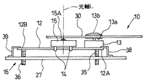
以下、本発明の実施の形態を図1乃至図8に基づいて詳細に説明する。まず、図1及び図2を用いて本実施の形態におけるピックアップ移動機構について説明する。
図1に示すように、ピックアップ移動機構10は、記録媒体30(図2参照)の情報記録面に記録された情報を読み取るピックアップ15と、そのピックアップ15を記録媒体30の情報記録面に平行で且つその径方向に沿って移動させる送りねじ11、ガイドシャフト12及び駆動モータ22とを備えている。
【0020】
ピックアップ15にはその内部に図示せぬ発光素子(レーサダイオード)を備えており、その発光素子から発射されるレーザ光を集光して情報記録面に照射させる対物レンズ15Aがピックアップ15の上面から情報記録面と対面するようにして露出されている。
【0021】
ピックアップ15の内部には、情報記録面から反射された反射光(戻り光)を受光して光電変換する受光部が備えられている。また、ピックアップ15の下面には、ガイドシャフト12を支持する略L字状のガイド支持部14がその下面から突出するようにして所定間隔空けて2つ設けられている。
【0022】
また、ピックアップ15の下面におけるガイド支持部14と反対側には、図2に示すように送りねじ11を挿通する挿通孔を有する送りねじ支持部13がその下面から突出するようにして所定間隔空けて2つ設けられている。
ピックアップ15の下面における2つの送りねじ支持部13の間には、送りねじ11に形成されたねじ部と噛合するラック15B(図2参照)が形成されている。
【0023】
ピックアップ15は、これらガイド支持部14,14と送りねじ支持部13,13により送りねじ11とガイドシャフト12に4点支持されている。
また、送りねじ11の端部近傍には、駆動モータ22が配されており、その駆動モータ22の回転軸には駆動ギア21が取り付けられている。また、その駆動ギア21は、送りねじ11の端部に形成された被駆動ギア部19に噛合している。
【0024】
なお、ガイドシャフト12と送りねじ11とは互いに平行となるように配されており、また、図2に示すようにそれらガイドシャフト12と送りねじ11とは、スピンドルモータ13の回転軸に取り付けられたターンテーブル13aとクランパ13bとにより所定位置に装着された記録媒体30の情報記録面の径方向に沿って延在している。
また、それらガイドシャフト12と送りねじ11とは、その情報記録面に対向するようにして配されている。
【0025】
このように構成されたピックアップ移動機構10は、駆動モータ22からの駆動力が駆動ギア21を介して送りねじ11の被駆動ギア部19に伝達されることによりピックアップを移動させる。
つまり、駆動モータ22からの駆動力を受けた送りねじ11は、正方向及び負方向に回転駆動され、その回転駆動によりピックアップ15がガイドシャフト12に沿って、すなわち記録媒体30の情報記録面に沿って移動される。
【0026】
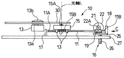
次に上述したピックアップ移動機構10におけるピックアップ15の傾きを調整するスキュー調整機構16について図2乃至図5を用いて説明する。スキュー調整機構16は、送りねじ11における記録媒体30の情報記録面の内周側に位置する端部11A(以下、単に「一端」として説明する)を支持する支持部材17と、送りねじ11における記録媒体30の情報記録面の外周側に位置する端部11B(以下、単に「他端」として説明する)を支持する支持部材18と、ガイドシャフト12における記録媒体30の情報記録面の内周側に位置する端部12A(以下、ガイドシャフト一端と称して説明する)を支持する弾性支持部38と、ガイドシャフト12における記録媒体30の情報記録面の外周側に位置する端部12B(以下、ガイドシャフト他端と称して説明する)を支持する弾性支持部39と、支持部材18と駆動モータ22を支持する弾性支持部25とを備えている。
【0027】
また、スキュー調整機構16は、ガイドシャフト12と送りねじ11の各々を移動調整する第1調整ねじ26、第2調整ねじ35及び第3調整ねじ36を備えている。
【0028】
支持部材17は、シャーシ等の基板27から立設されており、その上方に形成された図示せぬ係合凹部に送りねじ11の一端11Aが回動可能に係合されている。支持部材18は、弾性支持部25に取り付けられており、その下方に形成された図示せぬ係合凹部に送りねじ11の他端11Bが回動可能に係合されている。
【0029】
弾性支持部38は、略S字状に形成された板バネ等の弾性部材で構成され、その下端部が基板27に取り付けられ、その上端部がガイドシャフト一端12Aの上側に接触してそのガイドシャフト一端12Aを下方向に付勢している。
弾性支持部39は、略S字状に形成された板バネ等の弾性部材で構成され、その下端部が基板27に取り付けられ、その上端部がガイドシャフト他端12Bの上側に接触してそのガイドシャフト他端12Bを下方向に付勢している。
【0030】
これら弾性支持部38と弾性部材39とによりガイドシャフト12の両端には均等の付勢力が下方向にかけられており、第2調整ねじ35と第3調整ねじ36による移動調整がなされない場合には、それら均等の付勢力によりガイドシャフト12は基板27に対して平行状態に保持される。
【0031】
弾性支持部25は、図3に示すように略L字状に形成された板バネ等の弾性部材で構成されている。弾性支持部25は、基板27に平行に配置される平板部25Aと、その平板部25Aの端部から立設する立設部25Bとからなる。
立設部25Bにおける平板部25A側の側面には、駆動モータ22がビス(図示せず)等により固定されており、その側面に形成された貫通孔25Cから駆動モータ22の回転軸が挿通されている。
【0032】
また、立設部25Bの側端部には、平板部25Aが延在する方向とは逆方向に延在する略コ字状の取付部24が形成されており、その取付部24には支持部材18がビス23等により取り付けられている。
平板部25Aは、基板27上に平行に配置されるとともに、立設部25Bと反対側の端部近傍がビス23A(図5参照)等により基板27に取り付けられている。
また、平板部25Aの下面における立設部25B寄りには、第1調整ねじ26の上端が当接されている。
【0033】
第1調整ねじ26は、基板27にねじ結合されている。また、その第1調整ねじ26の上端には弾性支持部25が当接しており、その第1調整ねじ26が治具により上方向に移動されることにより弾性支持部25の平板部25Aが基板27との結合点を支点として弾性変形され(図5参照)、弾性支持部25に支持されている支持部材18が上方に移動される。
【0034】
この弾性支持部25は、第1調整ねじ26を下方向に付勢しており、その第1調整ねじ26の上方への移動により弾性支持部25の平板部25Aに対しその付勢力に抗した力が加えられ弾性変形される。
そして、支持部材18が第1調整ねじ26により弾性支持部25を介して移動されることにより、その支持部材18に支持されている送りねじ11の他端11Bが上下方向に移動調整される。
【0035】
図4に示すように、第2調整ねじ35は、基板27にねじ結合されている。また、第2調整ねじ35の上端は、ガイドシャフト12のガイドシャフト一端12A近傍の下側に当接している、その第2調整ねじ35が治具により上下方向に移動されることにより、ガイドシャフト12のガイドシャフト一端12Aが上下方向に移動調整される。
【0036】
第3調整ねじ36は、基板27にねじ結合されている。また、第3調整ねじ36の上端は、ガイドシャフト12のガイドシャフト他端12B近傍の下側に当接している。その第3調整ねじ36が治具により上下方向に移動されることにより、ガイドシャフト12のガイドシャフト他端12Bが上下方向に移動調整される。
【0037】
なお、これら第1調整ねじ26、第2調整ねじ35及び第3調整ねじ36の各々が所定の高さにあるとき、送りねじ11とガイドシャフト12に移動可能に取り付けられたピックアップ15は水平状態になっている。
この所定の高さは、製品の設計等により適宜最適な高さに設定される。本実施の形態においては、基板27から送りねじ11、ガイドシャフト12までの高さが1mmに設定される。
【0038】
これは、支持部材17に形成される係合凹部の位置により設定されることになる。すなわち、第1調整ねじ26、第2調整ねじ35及び第3調整ねじの各々がその設定された高さに適合する高さにあるときにピックアップ15が水平状態になる。
【0039】
なお、図2、図4及び図5は、水平状態にあるピックアップ15を示している。同図から分かるように、第1調整ねじ26、第2調整ねじ35及び第3調整ねじ36の各々は基板27から所定の高さに位置付けた状態にある。
【0040】
これら第1調整ねじ26、第2調整ねじ35及び第3調整ねじ36によりピックアップ15の傾きが調整される。なお、第1調整ねじ26と第3調整ねじ36により対物レンズ15Aの光軸Lのラジアル方向への調整が行われ、第2調整ねじ35と第3調整ねじ36により対物レンズ15Aの光軸L(図2参照)のタンジェンシャル方向への調整が行われる。
【0041】
次に図6乃至図8を用いてスキュー調整機構16の作用について説明する。まず、第1調整ねじ26と第3調整ねじ36による対物レンズ15Aの光軸Lのラジアル方向への調整について説明する。
【0042】
第1調整ねじ26と第3調整ねじ36を所定の高さに位置付けた状態、すなわち、図4及び図5に示すピックアップ15を水平状態にする高さに位置付けた状態から、第1調整ねじ26と第3調整ねじ36の各々を治具を用いて時計回り方向に回転させることにより、図6Aおよび図7Aに示すように第1調整ねじ26と第3調整ねじ36を基板27に対して上昇させる。
すると、送りねじ11とガイドシャフト12とは、各々支持部材17の係合凹部と第2調整ねじ35の当接点を支点として任意の上り勾配に傾斜させることができる。
【0043】
このとき、第1調整ねじ26と第3調整ねじ36を同期を取りながら上昇させる必要がある。例えば、支持部材17と第2調整ねじ35とがピックアップ15の移動方向に対して垂直な方向に平行配置させ、かつ第1調整ねじ26と第3調整ねじ36とがピックアップ15の移動方向に対して垂直な方向に並行配置させる。そして、第1調整ねじ26の径およびねじピッチを第3調整ねじ36の径およびねじピッチと同等にして第1調整ねじ26を時計回り方向に1回転させたら、第3調整ねじ36を時計回り方向に1回転させるように交互に1回転ずつ回転動作させる。そうすれば、各々同じ高さずつ上昇させることができる。
【0044】
よって、送りねじ11とガイドシャフト12とは、常に同じ角度ずつ傾斜されピックアップ15の傾きが安定した状態で調整されることになる。なお、第1調整ねじ26と第3調整ねじ36とは各々弾性支持部25と弾性支持部39により下方向に付勢されているため、第1調整ねじ26と第3調整ねじ36を上昇させる際にはその付勢力がトリガーとなってそれら調整ねじが上昇されすぎることを防止できる。
【0045】
一方、第1調整ねじ26と第3調整ねじ36を所定の高さに位置付けた状態、すなわち、図2、図4及び図5に示すピックアップ15を水平状態にする高さに位置付けた状態から、第1調整ねじ26と第3調整ねじ36の各々を治具を用いて反時計回り方向に回転させることにより、図6Bおよび図7Bに示すように第1調整ねじ26と第3調整ねじ36を基板27に対して下降させる。
【0046】
すると、送りねじ11とガイドシャフト12とは、各々支持部材17の係合凹部と第2調整ねじ35の当接点を支点として任意の下り勾配に傾斜させることができる。このとき、第1調整ねじ26と第3調整ねじ36を同期を取りながら下降させる必要がある。
【0047】
その場合も上述した上昇させるときと同様に、例えば、第1調整ねじ26の径およびねじピッチを第3調整ねじ36の径およびねじピッチと同等にして第1調整ねじ26を反時計回り方向に1回転させたら、第3調整ねじ36を反時計回り方向に1回転させるように交互に1回転ずつ回転動作させる。
そうすれば、各々同じ高さずつ下降させることができる。よって、送りねじ11とガイドシャフト12とは、常に同じ角度ずつ傾斜されピックアップ15の傾きが安定した状態で調整されることになる。
【0048】
このようにして、対物レンズ15Aの光軸Lのラジアル方向への傾きが送りねじ11とガイドシャフト12を移動調整することにより調整され、そして、その光軸Lと情報記録面とのなす角度が調整される。
【0049】
次に、第2調整ねじ35と第3調整ねじ36による対物レンズ15Aの光軸Lのタンジェンシャル方向への調整について説明する。
第2調整ねじ35と第3調整ねじ36を所定の高さに位置付けた状態、すなわち、図2、図4及び図5に示すピックアップ15を水平状態にする高さに位置付けた状態から、第2調整ねじ35と第3調整ねじ36の各々を治具を用いて時計回り方向に回転させることにより、図8Aと図9Aに示すように第2調整ねじ35と第3調整ねじ36を基板27に対して上昇させる。
【0050】
すると、ガイドシャフト12は、送りねじ11を支軸として任意の高さに上昇させることができる。このとき、第2調整ねじ35と第3調整ねじ36を同期を取りながら上昇させる必要がある。
例えば、第2調整ねじ35の径およびねじピッチを第3調整ねじ36の径およびねじピッチと同等にして第2調整ねじ35を時計回り方向に1回転させたら、第3調整ねじ36を時計回り方向に1回転させるように交互に1回転ずつ回転動作させる。
【0051】
そうすれば、各々同じ高さずつ上昇させることができる。よって、送りねじ11との平行状態を保ちながらガイドシャフト12が上昇されピックアップ15の傾きが安定した状態で調整されることになる。
なお、第2調整ねじ35と第3調整ねじ36とは各々弾性支持部38と弾性支持部39により下方向に付勢されているため、第2調整ねじ35と第3調整ねじ36を上昇させる際にはその付勢力がトリガーとなってそれら調整ねじが上昇されすぎることを防止できる。
【0052】
一方、第2調整ねじ35と第3調整ねじ36を所定の高さに位置付けた状態、すなわち、図2、図4及び図5に示すピックアップ15を水平状態にする高さに位置付けた状態から、第2調整ねじ35と第3調整ねじ36の各々を治具を用いて反時計回り方向に回転させることにより、図8Bと図9Bに示すように第2調整ねじ35と第3調整ねじ36を基板27に対して下降させる。
【0053】
すると、ガイドシャフト12は、送りねじ11を支軸として任意の高さに下降させることができる。このとき、第2調整ねじ35と第3調整ねじ36を同期を取りながら下降させる必要がある。
その場合も上述した上昇させるときと同様に、例えば、第2調整ねじ35の径およびねじピッチを第3調整ねじ36の径およびねじピッチと同等にして第2調整ねじ35を反時計回り方向に1回転させたら、第3調整ねじ36を反時計回り方向に1回転させるように交互に1回転ずつ回転動作させる。
【0054】
そうすれば、各々同じ高さずつ下降させることができる。よって、送りねじ11との平行状態を保ちながらガイドシャフト12が下降されピックアップ15の傾きが安定した状態で調整されることになる。
【0055】
このようにして、対物レンズ15Aの光軸Lのタンジェンシャル方向への傾きがガイドシャフト12を移動調整することにより調整され、そして、その光軸Lと情報記録面とのなす角度が調整される。
【0056】
以上、詳述したように、本実施の形態におけるピックアップのスキュー調整機構16では、送りねじ11とガイドシャフト12をともに移動可能とし、それらを移動調整することによりピックアップ15の傾き調整を可能としている。
従って、ピックアップ15の傾きを調整した後、送りねじ11とガイドシャフト12との平行状態に微妙なズレを生じさせることがない。
【0057】
よって、送りねじ11や駆動モータ22等に余計な負荷をかけることなく、ピックアップの傾き調整後も安定したピックアップ15の移動が可能となる。また、送りねじ11の移動調整の際に駆動モータ22も移動させているため、送りねじ11の被駆動ギア19と駆動モータ22の回転軸に設けられた駆動ギア21との位置ズレを引き起こすことなく、適正な配置関係のまま調整することができる。
【0058】
また、ピックアップ移動機構10における送りねじ11とガイドシャフト12を各々1つずつにしているため、部品点数の削減が図れるとともに、それらの移動調整が容易に行える。
また、ピックアップ移動機構10における送りねじ11とガイドシャフト12をピックアップ15の下側に配置しているため小型化が図れるとともに、それらの移動調整が容易に行える。
【0059】
なお、前記実施形態では、ピックアップのスキュー調整機構16を例えばDVD等の記録媒体の再生装置に適用した例について説明したが、これに限らないで、例えばCDの再生装置に適用することも可能である。
【0060】
さらに、本発明は、前述した実施形態に限定されるものでなく、適宜な変形,改良等が可能であり、前述した実施形態において例示した送りねじ,ガイドシャフト,ピックアップおよび記録媒体等の材質,形状,寸法,形態,数,配置個所,厚さ寸法等は本発明を達成できるものであれば任意であり、限定されない。
【0061】
【発明の効果】
以上、説明したように、本発明によれば、請求項1に記載したように、送りねじとガイドシャフトをともに移動可能とし、それらを移動調整することによりピックアップの傾き調整を可能としている。
【0062】
よって、ピックアップの傾きを調整した後、送りねじとガイドシャフトとの平行状態に微妙なズレを生じさせることがない。
したがって、送りねじや駆動モータ等に余計な負荷をかけることなく、ピックアップの傾き調整後も安定したピックアップの移動が可能となる。
【0063】
さらに、送りねじの移動調整の際に駆動モータも移動させることで、送りねじ11の被駆動ギアと駆動モータの回転軸に設けられた駆動ギアとの位置ズレを引き起こすことなく、適正な配置関係のまま調整することができる。
【0064】
また、請求項2に記載したように、ピックアップ移動機構における送りねじとガイドシャフトを各々1つずつにしているため、部品点数の削減が図れるとともに、それらの移動調整が容易に行える。
【0065】
また、請求項3に記載したように、ピックアップ移動機構における送りねじとガイドシャフトをピックアップの下側に配置しているため小型化が図れるとともに、それらの移動調整が容易に行える。
【図面の簡単な説明】
【図1】本発明に係るピックアップのスキュー調整機構を備えたピックアップ移動機構を示す斜視図である。
【図2】図1の矢視A図である。
【図3】本発明に係るピックアップのスキュー調整機構を備えたピックアップ移動機構を示す要部斜視図である。
【図4】図1の矢視B図である。
【図5】図3の矢視C図である。
【図6】本発明に係るピックアップのスキュー調整機構で送りねじを操作する例を示す説明図である。
【図7】本発明に係るスキュー調整機構でガイドシャフトを操作する例を示す説明図である。
【図8】本発明に係るピックアップのスキュー調整機構の第2、第3の調整ねじの作用を示す説明図である。
【図9】本発明に係るピックアップのスキュー調整機構の第2、第3の調整ねじの作用を示す説明図である。
【図10】従来のピックアップ移動機構を示す斜視図である。
【図11】従来のピックアップ移動機構を示す側面図である。
【図12】従来のピックアップから記録媒体に光を照射する状態を示す説明図である。
【符号の説明】
10 ピックアップ移動機構
11 送りねじ
12 ガイドシャフト
15 ピックアップ
16 ピックアップのスキュー調整機構
22 駆動モータ
30 記録媒体[0001]
TECHNICAL FIELD OF THE INVENTION
The present invention relates to a pickup for reading information recorded on an information recording surface of a recording medium and adjusting a tilt of the pickup with respect to the information recording surface, the pickup being movable parallel to the information recording surface and along the radial direction. The present invention relates to a skew adjustment mechanism.
[0002]
[Prior art]
As shown in FIG. 10, in a conventional
A
Then, the
[0003]
As shown in FIG. 11, the feed screw 101 (see FIG. 10) and the pair of
Accordingly, the
[0004]
On the other hand, the
Then, the reflected light (return light) reflected from the information recording surface is received by a light receiving unit (not shown) via the
[0005]
That is, the
[0006]
In order to accurately read the information recorded on the information recording surface by the laser light, it is necessary to adjust the angle α between the optical axis L of the
In other words, in order to accurately receive the reflected light from the information recording surface at the light receiving unit of the
[0007]
Particularly, in a high-density optical recording medium such as a DVD (Digital Versatile Disc) or the like, since the recording pits are dense, the inclination of the
[0008]
The tilt adjustment of the
That is, the adjustment in the radial direction of the optical axis L of the
[0009]
[Problems to be solved by the invention]
However, the conventional tilt adjustment of the
[0010]
For this reason, after the inclination of the
[0011]
One object of the present invention is not to apply a load to a pickup moving mechanism that moves the pickup in the radial direction of the information recording surface of the recording medium after adjusting the inclination of the pickup. It is to provide a skew adjustment mechanism.
[0012]
[Means for Solving the Problems]
In order to achieve the above object, the present invention provides a pickup for irradiating an information recording surface of a recording medium with light to read information recorded on the information recording surface, as described in claim 1, A drive screw and a guide shaft, each of which is movably held and which is arranged in parallel with each other, and a driving force is applied to the feed screw in order to move the pickup in parallel with the information recording surface and along the same diameter. A pickup skew adjusting mechanism for adjusting a tilt of the pickup with respect to the information recording surface, wherein each of the feed screw and the guide shaft is movable, Adjusting the tilt of the pickup by moving and adjusting each of the screw and the guide shaft. And butterflies.
[0013]
In the pickup skew adjustment mechanism configured as described above, both the feed screw and the guide shaft can be moved, and the inclination of the pickup can be adjusted by moving and adjusting them.
Therefore, after the inclination of the pickup is adjusted, there is no possibility that a slight deviation occurs in the parallel state between the feed screw and the guide shaft.
Therefore, it is possible to prevent an unnecessary load from being applied to the feed screw, the drive motor, and the like.
[0014]
Further, by moving the drive motor at the time of adjusting the movement of the feed screw, it is possible to prevent the positional shift between the driven gear of the
[0015]
Further, in the present invention, as described in claim 2, the pick-up moving mechanism includes one each of the feed screw and the guide shaft, and moves and adjusts each of the feed screw and the guide shaft. The tilt of the pickup is adjusted.
[0016]
Since one feed screw and one guide shaft are used in the pickup moving mechanism, the number of parts can be reduced.
[0017]
Further, in the present invention, as described in claim 3, the pickup moving mechanism arranges the feed screw and the guide shaft below the pickup respectively, and moves and adjusts each of the feed screw and the guide shaft. In this case, the tilt of the pickup is adjusted.
[0018]
Since the feed screw and the guide shaft in the pickup moving mechanism are arranged below the pickup, downsizing can be achieved.
[0019]
BEST MODE FOR CARRYING OUT THE INVENTION
Hereinafter, an embodiment of the present invention will be described in detail with reference to FIGS. First, a pickup moving mechanism according to the present embodiment will be described with reference to FIGS.
As shown in FIG. 1, the
[0020]
The
[0021]
Inside the
[0022]
A feed
A
[0023]
The
A
[0024]
The
The
[0025]
The
That is, the
[0026]
Next, a
[0027]
The
[0028]
The
[0029]
The
The
[0030]
An equal urging force is applied to both ends of the
[0031]
As shown in FIG. 3, the
A
[0032]
A substantially U-shaped mounting
The
The upper end of the first adjusting
[0033]
The
[0034]
The
Then, the
[0035]
As shown in FIG. 4, the second adjusting
[0036]
The
[0037]
When each of the
The predetermined height is appropriately set to an optimum height according to the design of the product or the like. In the present embodiment, the height from the
[0038]
This is set by the position of the engagement recess formed in the
[0039]
FIGS. 2, 4 and 5 show the
[0040]
The inclination of the
[0041]
Next, the operation of the
[0042]
From a state where the
Then, the
[0043]
At this time, it is necessary to raise the first adjusting
[0044]
Therefore, the
[0045]
On the other hand, from the state where the
[0046]
Then, the
[0047]
In this case, similarly to the case of raising the above, for example, the diameter and the screw pitch of the first adjusting
Then, they can be lowered by the same height. Therefore, the
[0048]
Thus, the inclination of the optical axis L of the
[0049]
Next, adjustment of the optical axis L of the
From a state where the
[0050]
Then, the
For example, when the diameter and the screw pitch of the
[0051]
Then, each can be raised by the same height. Therefore, the
Since the second adjusting
[0052]
On the other hand, from the state where the
[0053]
Then, the
In this case, similarly to the case of raising the above, for example, the diameter and the screw pitch of the second adjusting
[0054]
Then, they can be lowered by the same height. Therefore, the
[0055]
In this manner, the inclination of the optical axis L of the
[0056]
As described in detail above, in the
Therefore, after the inclination of the
[0057]
Therefore, it is possible to stably move the
[0058]
In addition, since the
In addition, since the
[0059]
In the above-described embodiment, an example in which the
[0060]
Further, the present invention is not limited to the above-described embodiment, but can be appropriately modified, improved, and the like. The materials such as the feed screw, the guide shaft, the pickup, and the recording medium exemplified in the above-described embodiment can be used. The shape, size, form, number, location, thickness, etc. are arbitrary and not limited as long as the present invention can be achieved.
[0061]
【The invention's effect】
As described above, according to the present invention, the feed screw and the guide shaft can be moved together, and the tilt of the pickup can be adjusted by moving and adjusting them.
[0062]
Therefore, after the inclination of the pickup is adjusted, there is no possibility that a slight deviation occurs in the parallel state between the feed screw and the guide shaft.
Therefore, the pickup can be stably moved even after the inclination of the pickup is adjusted without applying an extra load to the feed screw, the drive motor, and the like.
[0063]
Further, by moving the drive motor at the time of adjusting the movement of the feed screw, the positional relationship between the driven gear of the
[0064]
Further, as described in claim 2, since the feed screw and the guide shaft in the pickup moving mechanism are each one, the number of parts can be reduced, and the movement can be easily adjusted.
[0065]
In addition, since the feed screw and the guide shaft in the pickup moving mechanism are arranged below the pickup as described in claim 3, the size can be reduced and the movement adjustment thereof can be easily performed.
[Brief description of the drawings]
FIG. 1 is a perspective view showing a pickup moving mechanism provided with a skew adjustment mechanism for a pickup according to the present invention.
FIG. 2 is a diagram viewed from the arrow A in FIG. 1;
FIG. 3 is a perspective view of a main part showing a pickup moving mechanism provided with a skew adjustment mechanism of the pickup according to the present invention.
FIG. 4 is a diagram viewed from an arrow B in FIG. 1;
FIG. 5 is an arrow C view of FIG. 3;
FIG. 6 is an explanatory view showing an example in which a feed screw is operated by the skew adjustment mechanism of the pickup according to the present invention.
FIG. 7 is an explanatory diagram showing an example of operating a guide shaft with the skew adjustment mechanism according to the present invention.
FIG. 8 is an explanatory view showing the operation of second and third adjustment screws of the skew adjustment mechanism of the pickup according to the present invention.
FIG. 9 is an explanatory view showing the operation of the second and third adjustment screws of the skew adjustment mechanism of the pickup according to the present invention.
FIG. 10 is a perspective view showing a conventional pickup moving mechanism.
FIG. 11 is a side view showing a conventional pickup moving mechanism.
FIG. 12 is an explanatory diagram showing a state in which light is applied to a recording medium from a conventional pickup.
[Explanation of symbols]
10 Pickup moving mechanism
11 Lead screw
12 Guide shaft
15 Pickup
16 Pickup skew adjustment mechanism
22 Drive motor
30 recording media
Claims (3)
前記情報記録面に対する前記ピックアップの傾きを調整するピックアップのスキュー調整機構であって、
前記送りねじおよび前記ガイドシャフトの各々を移動可能とし、前記送りねじおよび前記ガイドシャフトの各々を移動調整することにより前記ピックアップの傾きを調整することを特徴とするピックアップのスキュー調整機構。A pickup for irradiating the information recording surface of the recording medium with light to read information recorded on the information recording surface, a feed screw and a guide shaft each of which movably holds the pickup and are arranged in parallel with each other, A pickup motor that includes a drive motor that applies a driving force to the feed screw in order to move the pickup in parallel with the information recording surface and along the same diameter.
A skew adjustment mechanism of a pickup that adjusts an inclination of the pickup with respect to the information recording surface,
A skew adjustment mechanism for a pickup, wherein each of the feed screw and the guide shaft is movable, and the tilt of the pickup is adjusted by moving and adjusting each of the feed screw and the guide shaft.
それら送りねじとガイドシャフトの各々を移動調整することにより前記ピックアップの傾きを調整することを特徴とする請求項1に記載のピックアップのスキュー調整機構。The pick-up moving mechanism includes one each of the feed screw and the guide shaft,
The skew adjustment mechanism for a pickup according to claim 1, wherein the inclination of the pickup is adjusted by moving and adjusting each of the feed screw and the guide shaft.
それら送りねじとガイドシャフトの各々を移動調整することにより前記ピックアップの傾きを調整することを特徴とする請求項1に記載のピックアップのスキュー調整機構。The pickup moving mechanism arranges the feed screw and the guide shaft below the pickup, respectively.
The skew adjustment mechanism for a pickup according to claim 1, wherein the inclination of the pickup is adjusted by moving and adjusting each of the feed screw and the guide shaft.
Priority Applications (2)
| Application Number | Priority Date | Filing Date | Title |
|---|---|---|---|
| JP2002226951A JP2004071018A (en) | 2002-08-05 | 2002-08-05 | Skew adjusting mechanism for pickup |
| US10/633,667 US6971115B2 (en) | 2002-08-05 | 2003-08-05 | Optical pickup apparatus |
Applications Claiming Priority (1)
| Application Number | Priority Date | Filing Date | Title |
|---|---|---|---|
| JP2002226951A JP2004071018A (en) | 2002-08-05 | 2002-08-05 | Skew adjusting mechanism for pickup |
Publications (2)
| Publication Number | Publication Date |
|---|---|
| JP2004071018A true JP2004071018A (en) | 2004-03-04 |
| JP2004071018A5 JP2004071018A5 (en) | 2005-10-20 |
Family
ID=31492198
Family Applications (1)
| Application Number | Title | Priority Date | Filing Date |
|---|---|---|---|
| JP2002226951A Pending JP2004071018A (en) | 2002-08-05 | 2002-08-05 | Skew adjusting mechanism for pickup |
Country Status (2)
| Country | Link |
|---|---|
| US (1) | US6971115B2 (en) |
| JP (1) | JP2004071018A (en) |
Families Citing this family (6)
| Publication number | Priority date | Publication date | Assignee | Title |
|---|---|---|---|---|
| DE10255259A1 (en) * | 2002-11-27 | 2004-06-09 | Philips Intellectual Property & Standards Gmbh | Device and alignment of a disk with respect to a disk head |
| US7342849B2 (en) * | 2003-01-31 | 2008-03-11 | Sony Corporation | Recording and/or playback device |
| KR20040083852A (en) * | 2003-03-25 | 2004-10-06 | 엘지전자 주식회사 | Skew adjustment apparatus for optical disc drive |
| JP4260668B2 (en) * | 2004-03-31 | 2009-04-30 | パイオニア株式会社 | Disk unit |
| FI20045327A0 (en) * | 2004-09-06 | 2004-09-06 | Nokia Corp | Radio system, base station controller and method for controlling data transmission |
| JP2006302372A (en) * | 2005-04-19 | 2006-11-02 | Funai Electric Co Ltd | Optical pickup device |
Family Cites Families (7)
| Publication number | Priority date | Publication date | Assignee | Title |
|---|---|---|---|---|
| US6052358A (en) * | 1996-10-04 | 2000-04-18 | Sony Corporation | Head feeding mechanism and optical pick-up feeding mechanism |
| JPH10116479A (en) * | 1996-10-11 | 1998-05-06 | Matsushita Electric Ind Co Ltd | Optical head adjusting device |
| JP3888506B2 (en) * | 1999-10-07 | 2007-03-07 | アルパイン株式会社 | Optical pickup transport mechanism |
| JP3668097B2 (en) * | 2000-03-17 | 2005-07-06 | 三洋電機株式会社 | Disc recording or reproducing apparatus having a pickup tilt adjusting mechanism |
| US6483798B1 (en) * | 2000-03-23 | 2002-11-19 | Acute Applied Technologies, Inc. | Tilt angle adjusting mechanism for optical pickup head |
| JP2002230922A (en) * | 2001-01-31 | 2002-08-16 | Sanyo Electric Co Ltd | Disk recorder or reproducer provided with pickup inclination adjusting mechanism |
| TW543906U (en) * | 2002-01-25 | 2003-07-21 | Lite On It Corp | Inclining angle adjusting device for compact disk drive |
-
2002
- 2002-08-05 JP JP2002226951A patent/JP2004071018A/en active Pending
-
2003
- 2003-08-05 US US10/633,667 patent/US6971115B2/en not_active Expired - Fee Related
Also Published As
| Publication number | Publication date |
|---|---|
| US20040027977A1 (en) | 2004-02-12 |
| US6971115B2 (en) | 2005-11-29 |
Similar Documents
| Publication | Publication Date | Title |
|---|---|---|
| JPH11250595A (en) | Disk player capable of adjusting tilt of optical pickup | |
| JP2004071018A (en) | Skew adjusting mechanism for pickup | |
| JP2007109362A (en) | Optical disk drive | |
| JP2793176B2 (en) | Disc player pickup tilt adjustment device | |
| JP4226560B2 (en) | Disc player | |
| JP2000048376A (en) | Pickup adjusting mechanism | |
| KR100504774B1 (en) | Skew Adjustment Method and Adjustment Device for Optical Disc Drive | |
| JP4155266B2 (en) | Optical pickup angle and distance adjustment method | |
| JP2004326938A (en) | Media driving device | |
| JP2007280494A (en) | Optical disk drive | |
| JP2000011386A (en) | Optical pickup transfer device | |
| JP2003022553A (en) | Optical disk device | |
| JP4493528B2 (en) | Optical axis adjusting device and adjusting method for optical pickup | |
| KR100509034B1 (en) | A skew adjusting apparatus for disk drive | |
| KR100246476B1 (en) | Apparatus of optical axis skew correction | |
| JP5097378B2 (en) | Optical disk device | |
| WO2000022616A1 (en) | Recording and/or reproducing apparatus | |
| KR100585671B1 (en) | Automatic tilt control device in optical disk drive | |
| KR20030034445A (en) | Tilt adjustment device for optical disc drive | |
| JP2002288861A (en) | Optical disk recording and reproducing device | |
| JP2006065910A (en) | Optical disk device | |
| KR20080047040A (en) | Center control structure of an optical disc player | |
| JP2008257775A (en) | Position adjustment mechanism for spindle motor | |
| JP2006236401A (en) | Disk unit | |
| JPH0760525B2 (en) | Optical pickup attitude adjustment mechanism |
Legal Events
| Date | Code | Title | Description |
|---|---|---|---|
| A521 | Written amendment |
Free format text: JAPANESE INTERMEDIATE CODE: A523 Effective date: 20050622 |
|
| A621 | Written request for application examination |
Free format text: JAPANESE INTERMEDIATE CODE: A621 Effective date: 20050704 |
|
| A977 | Report on retrieval |
Free format text: JAPANESE INTERMEDIATE CODE: A971007 Effective date: 20070628 |
|
| A131 | Notification of reasons for refusal |
Free format text: JAPANESE INTERMEDIATE CODE: A131 Effective date: 20070704 |
|
| A521 | Written amendment |
Free format text: JAPANESE INTERMEDIATE CODE: A523 Effective date: 20070830 |
|
| A02 | Decision of refusal |
Free format text: JAPANESE INTERMEDIATE CODE: A02 Effective date: 20080117 |