JP2004051080A - Daytime lighting device for vehicle - Google Patents
Daytime lighting device for vehicle Download PDFInfo
- Publication number
- JP2004051080A JP2004051080A JP2003016424A JP2003016424A JP2004051080A JP 2004051080 A JP2004051080 A JP 2004051080A JP 2003016424 A JP2003016424 A JP 2003016424A JP 2003016424 A JP2003016424 A JP 2003016424A JP 2004051080 A JP2004051080 A JP 2004051080A
- Authority
- JP
- Japan
- Prior art keywords
- daytime
- vehicle
- light
- lighting device
- daytime running
- Prior art date
- Legal status (The legal status is an assumption and is not a legal conclusion. Google has not performed a legal analysis and makes no representation as to the accuracy of the status listed.)
- Pending
Links
Images


Classifications
-
- Y—GENERAL TAGGING OF NEW TECHNOLOGICAL DEVELOPMENTS; GENERAL TAGGING OF CROSS-SECTIONAL TECHNOLOGIES SPANNING OVER SEVERAL SECTIONS OF THE IPC; TECHNICAL SUBJECTS COVERED BY FORMER USPC CROSS-REFERENCE ART COLLECTIONS [XRACs] AND DIGESTS
- Y02—TECHNOLOGIES OR APPLICATIONS FOR MITIGATION OR ADAPTATION AGAINST CLIMATE CHANGE
- Y02B—CLIMATE CHANGE MITIGATION TECHNOLOGIES RELATED TO BUILDINGS, e.g. HOUSING, HOUSE APPLIANCES OR RELATED END-USER APPLICATIONS
- Y02B20/00—Energy efficient lighting technologies, e.g. halogen lamps or gas discharge lamps
- Y02B20/40—Control techniques providing energy savings, e.g. smart controller or presence detection
Abstract
Description
【0001】
【発明の属する技術分野】
本発明は、昼間点灯により車両の存在を強調する車両用昼間点灯装置に関し、特に、四輪車(自動車)に付設される車両用昼間点灯装置に関する。
【0002】
【従来の技術】
車両走行において、事故の発生を防止するには、自分が他者(他の車両や歩行者)の存在を正確に認識するだけでなく、自分が運転する車両の存在を他者に確実に認識させることが重要とされている。
夜間の走行においては、ヘッドライトの点灯により、車両の存在が強調されるので、相互の認識が容易になるが、昼間の走行においては、自然光のみで車両を視認するため、状況によって相互の認識が不足する可能性がある。
【0003】
近年、ヘッドライトの被視認効果に着目し、昼間走行においてもヘッドライトを点灯させることが奨励されており、自動二輪車では、既に、ヘッドライトの常時点灯(昼間点灯)が一般化している。
一方、四輪車においても、一部の企業(運送会社、タクシー会社など)ではヘッドライトの昼間点灯を実施しており、その事故防止効果が報告されている。
【0004】
なお、従来、車両用ヘッドライトの点灯制御に関する技術が、種々提案されている。
たとえば、車載用のバッテリからの直流を交流に変換するインバータと、そのバッテリからの直流とインバータからの交流とを加算する加算手段とを備えることによって、より高輝度で、寿命を縮めることのない、白熱電球等からなるヘッドライトを点灯する技術が提案されている(例えば、特許文献1参照。)。
【0005】
【特許文献1】
特許第3080620号
【0006】
【発明が解決しようとする課題】
しかしながら、従来の四輪車においては、キースイッチ(エンジンキー)のON/OFFと無関係に、ヘッドライトを点灯/消灯させるため、ヘッドライトの昼間点灯を実施しようとした場合、ライティングスイッチの意識的な点灯操作が必要になるとともに、降車時には、ライティングスイッチを消灯操作する必要がある。そのため、ヘッドライトのつけ忘れが発生するばかりでなく、ヘッドライトの消し忘れによってバッテリを放電させる可能性がある。
【0007】
また、ヘッドライトは、その明るさや向きが、夜間点灯を基準として設定されているため、昼間の点灯においては、良好な視認性を発揮できないという問題がある。
【0008】
また、ヘッドライトの光源には、通常、ハロゲンランプなどの白熱球が使用されるため、ヘッドライトを昼間点灯させると、光源の寿命が縮まるばかりでなく、消費電力の増大に伴って、バッテリの寿命が短くなったり、燃費が低下したりする不都合がある。
【0009】
さらに、たとえば、ヘッドライトとは別の新たなライトを車体前面に設けて、これを点灯させることとした場合、この新たなライトの点灯が他者にとって迅速かつ確実に認識できることが必要とされていた。
ところが、昼間は、自然光だけで周囲が十分明るく、人間の目もその明るさに慣らされていた。このため、光量の弱いライトを昼間屋外で単に点灯させただけでは、周囲の明るさにかき消されてしまい、その点灯が認識しずらくなることもあった。
【0010】
本発明は、上記の事情にかんがみなされたものであり、昼間点灯のつけ忘れを防止するとともに、消し忘れによるバッテリの放電を回避し、しかも、ヘッドライトによる昼間点灯に比べ、良好な視認性を発揮して、他者に対し自分の車両の存在を迅速かつ確実に認識させることが可能な車両用昼間点灯装置の提供を目的とする。
【0011】
【課題を解決するための手段】
上記目的を達成するため、本発明の車両用昼間点灯装置は、車両に付設され、その点灯により前記車両の存在を強調する昼間走行用ライトと、前記車両におけるキースイッチのON/OFF、又は、前記車両におけるエンジンの回転/停止に応じて、前記昼間走行用ライトを点灯/消灯させる昼間走行用ライト点灯回路とを有する構成としてある。
【0012】
車両用昼間点灯装置をこのような構成にすれば、従来のように、ライティングスイッチを意識的に操作することなく、キースイッチの操作だけで昼間点灯を行うことが可能になる。これにより、昼間点灯のつけ忘れを防止できるとともに、消し忘れによるバッテリの放電を回避することができる。
また、車両に昼間走行用ライトを付設するため、その明るさや向きを昼間点灯用に最適化することが可能になり、その結果、ヘッドライトを利用して昼間点灯を行う場合に比べ、良好な視認性を発揮することができる。
【0013】
また、本発明の車両用昼間点灯装置は、前記昼間走行用ライトの光源が、発光ダイオードで構成してある。
車両用昼間点灯装置をこのような構成にすれば、ハロゲンランプなどの白熱球を光源にする場合に比べ、消費電力を大幅に削減(1/50〜1/100)できるばかりでなく、消費電力の削減に伴い、燃費も向上させることができる。例えば、一台の車両において、燃費向上による消費燃料の節約が1リットル/月であったとしても、約7000万台の四輪車を保有する日本国内においては、約7000万リットル/月の燃料を節約することが可能になる。
【0014】
また、本発明の車両用昼間点灯装置は、前記昼間走行用ライト点灯回路が、昼夜を判別する昼夜判別手段と、この昼夜判別手段が夜間であると判定したとき、前記昼間走行用ライトを自動的に減光又は消灯させる減光・消灯手段とを有する構成としてある。
車両用昼間点灯装置をこのような構成にすれば、夜間走行において、昼間走行用ライトの光量が過剰になることを防止し、他の車両や歩行者にまぶしさを感じさせる不都合が回避される。
【0015】
また、本発明の車両用昼間点灯装置は、前記昼夜判別手段が、前記車両に設けられるヘッドライト又はスモールランプの点灯にもとづいて、夜間であると判定する構成としてある。
車両用昼間点灯装置をこのような構成にすれば、簡単な回路構成で昼夜判別が可能になり、コストダウンを図ることができる。
【0016】
また、本発明の車両用昼間点灯装置は、前記昼間走行用ライトが、二つを一組として、前記車両の前部に、所定の間隔で左右対称に配置される構成としてある。
車両用昼間点灯装置をこのような構成にすれば、昼間走行用ライトを左右非対称に配置した場合に比べ、車幅や車間距離の認識を容易にすることができる。
【0017】
また、本発明の車両用昼間点灯装置は、前記昼間走行用ライトが、前記ヘッドライトの下方近傍に配置される構成としてある。
車両用昼間点灯装置をこのような構成にすれば、昼間走行用ライトの視認性を向上させることができ、また、昼間走行用ライトとヘッドライトとを同時点灯させても違和感がない。
【0018】
また、本発明の車両用昼間点灯装置は、昼間走行用ライト点灯回路が、昼間走行用ライトへ供給される電圧及び/又は電流を制御する供給電力制御部を有した構成としてある。
車両用昼間点灯装置をこのような構成にすれば、昼間走行用ライトに供給される電圧や電流の制御が可能となるため、その昼間走行用ライトの明るさや点滅間隔等を調整できる。
これにより、昼間点灯に適した明るさや点滅間隔で昼間走行用ライトを点灯させることができるため、他者に対し自分の車両の存在を迅速かつ確実に認識させることが可能となる。
【0019】
また、本発明の車両用昼間点灯装置は、供給電力制御部が、電圧及び/又は電流をパルス波として出力する発振回路部と、この発振回路部から出力されるパルス波の周期及び/又は振幅を制御するパルス波制御回路部とを有した構成としてある。
車両用昼間点灯装置をこのような構成にすれば、パルス波の周期を制御して、昼間走行用ライトを点滅させることができる。これにより、車両の運転者は、他の車両の運転者や歩行者等に対し、注意を促すことができる。
【0020】
さらに、パルス波の周期や振幅を制御することで、昼間走行用ライトの点滅間隔や明るさも調整可能となる。これによっても、車両の運転者は、自分の車両の存在を他者に認識させて、注意を喚起させることができる。
加えて、走行の状態や周囲の状況等に応じた点滅時間や明るさを実現可能とすることで、他の車両等による自己の車両の認識を確実なものとすることができる。
【0021】
また、本発明の車両用昼間点灯装置は、供給電力制御部が、昼間走行用ライトへ供給されるバイアス分の電力として、一定値を示す電圧及び/又は電流を出力するバイアス電力供給回路部と、一定値を超過する分の電圧及び/又は電流について、周期を制御して、この周期制御した電圧及び/又は電流を昼間走行用ライトへ供給する超過電力制御回路部とを有した構成としてある。
【0022】
車両用昼間点灯装置をこのような構成にすれば、昼間走行用ライトの明るさを一定以上確保しながら、その明るさをより明るくしたり、また暗くしたりすることができる。これにより、自分の車両の存在を確実に他者に知らせて、その他者の注意を喚起させることができる。
さらに、周囲の明るさに応じて昼間走行用ライトの明るさを調整することにより、他者による自己の車両の認識を確実なものとすることができる。
本発明の車両用昼間点灯装置は、昼間にライトを点灯させるための装置であるが、たとえ昼間であっても、例えば、日差しの強い日と弱い日,屋外と構内,朝夕と日中などをそれぞれ比較すると、周囲の明るさはそれぞれ異っている。これに対し、人間の目は、周囲の明るさに適応して、取り込む光量を調節している。このことから、例えば、周囲の明るさが異なる複数の場所で(あるいは、周囲の明るさが異なる時間帯に)、それぞれ同一人が同じ光を見たとしても、その人が認識する光の明るさの程度はそれぞれ異なってくる。
そこで、点灯している昼間走行用ライトの明るさを一定以上保つことにより、他者が自分の車両の存在を認識し得る最低限の明るさを確保しておき、さらに、その昼間走行用ライトの明るさを周囲の明るさに応じて調整可能とすることで、どのような周囲の状況においても、その他者による認識をより確実なものとすることができる。
【0023】
また、本発明の車両用昼間点灯装置は、超過電力制御回路部が、一定値を超過する分の電圧及び/又は電流について、周期を制御して、この周期制御した電圧及び/又は電流を、バイアス電力供給回路部から受けた一定値を示す電圧及び/又は電流に加算して、昼間走行用ライトへ供給する構成としてある。
【0024】
車両用昼間点灯装置をこのような構成にすれば、バイアス電力供給回路部から出力されたバイアス電力(一定値を示す電圧又は電流)に、超過電力制御回路部で周期制御された電力(電圧又は電流)を加算して、昼間走行用ライトへ供給することができる。
このため、昼間走行用ライトは、バイアス電力によって、その明るさを一定以上確保することができ、かつ、周期制御された電力によって、その明るさをより明るくしたり、また暗くしたりすることができる。
このような明るさの制御が可能な昼間走行用ライトを点けることにより、他の車両の運転者や通行人等は、一定の光量を維持しつつ明るさが変化する昼間走行用ライトをいち早く発見できる。したがって、その昼間走行用ライトを点けた車両の運転者は、自分の車両の存在を確実に他者に知らせて、その他者の注意を喚起させることができる。
【0025】
また、本発明の車両用昼間点灯装置は、昼間走行用ライトが、色の異なる複数の光源を有した構成としてある。
車両用昼間点灯装置をこのような構成にすれば、昼間走行用ライトは、単色ではなく、複数の色で発光できる。このため、たとえば、赤色や黄色など注意をひくような色で発光することにより、他者に対し自分の車両の存在を迅速かつ確実に認識させることができる。
【0026】
また、本発明の車両用昼間点灯装置は、供給電力制御部が、複数の光源をそれぞれ同一又は異なるタイミングで点灯させる構成としてある。
車両用昼間点灯装置をこのような構成にすれば、昼間走行用ライトは、一定の明るさで単調に発光し続けるのではなく、異なる色で様々なタイミングにより発光することができる。
これにより、車両の運転手や歩行者等は、その発光色が変化する昼間走行用ライトを容易に見つけて、その車両の存在を確実に認識できる。
【0027】
また、本発明の車両用昼間点灯装置は、供給電力制御部が、複数の光源をそれぞれ交互に点滅させる構成としてある。
車両用昼間点灯装置をこのような構成にすれば、昼間走行用ライトにおいて、たとえば、赤色と黄色とが交互に点滅を繰り返すことから、他者に対し、自分の車両に注意をひかせることができる。このため、その他者は、昼間走行用ライトを点灯させている車両の存在を迅速かつ確実に認識できる。
【0028】
【発明の実施の形態】
以下、本発明の実施の形態について、図面を参照して説明する。
[第一実施形態]
まず、本発明の第一実施形態について、図1〜図5を参照して説明する。図1は、本発明の車両用昼間点灯装置が設けられた車両の正面図、図2及び図4は、第一実施形態における車両用昼間点灯装置の構成を示すブロック図、図3は、ライティングスイッチでの制御内容を示す説明図、図5は、第一実施形態における車両用昼間点灯装置の作用を示す説明図である。
【0029】
本実施形態の車両用昼間点灯装置100が設けられる車両10は、図1に示すように、四輪車であり、その前部(フロントグリル)11に、あらかじめ、ヘッドライト12と、スモールランプ13と、方向指示ランプ14とを備えている。
これらヘッドライト12、スモールランプ13及び方向指示ランプ14は、いずれも二つを一組とし、所定の間隔で左右対称に配置されている。
【0030】
ヘッドライト12とスモールランプ13は、図2に示すように、車内に設けられるライティングスイッチ15の切り替えによって点灯/消灯が切り替えられる。
例えば、図3に示すように、ライティングスイッチ15が“OFF”のときは、ヘッドライト12もスモールランプ13も消灯する。これに対し、ライティングスイッチ15が“第一ポジション(1段)”のときは、スモールランプ13だけが点灯し、ヘッドライト12は点灯しない。さらに、ライティングスイッチ15が“第二ポジション(2段)”のときは、ヘッドライト12とスモールランプ13との双方が点灯する。
方向指示ランプ14は、車内に設けられる方向指示レバー(図示せず)の操作に応じて、左右いずれかが選択的に点滅される。
【0031】
また、車両10は、図2に示すように、メインスイッチ及びエンジン始動スイッチとして機能するキースイッチ16を備えている。キースイッチ16に所定のキーを差し込み、このポジション(OFF)から第一ポジション(ON)まで回し操作すると、車両10に設けられる電装部品にバッテリ17の電流が供給される。更に、キーを、図示しない第二ポジション(ON)まで回し操作すると、スタータモータ(図示せず)が起動し、エンジンが始動される。
そして、エンジンが始動すると、車両10の走行が可能になるとともに、オルタネータ(図示せず)がエンジン動力で発電し、バッテリ17の充電が行われる。なお、バッテリ17から各電装品への電流供給は、ヒューズボックス18を経由して行われる。
【0032】
また、キースイッチ16とライティングスイッチ15は、図2に示すように、バッテリ17に並列に接続されている。したがって、ライティングスイッチ15によるヘッドライト12やスモールランプ13の点灯は、キースイッチ16のポジションと無関係に、常時許容される。
【0033】
車両用昼間点灯装置100は、図2に示すように、昼間走行用ライト110と、昼間走行用ライト点灯回路120とを備えて構成されている。昼間走行用ライト110は、左右方向に長い長方形のケース111と、このケース111の内部に前方を向いて配列される複数の発光ダイオード112と、ケース111の前面開口部を覆う透光性のカバー113とにより構成されている。
発光ダイオード112は、例えば、高輝度白色発光ダイオードであり、ハロゲンランプなどの白熱球に比べ、極めて少ない消費電力で点灯させることができる。
【0034】
昼間走行用ライト110は、図1に示すように、車両10の前部11に付設され、昼間走行用ライト点灯回路120によって昼間点灯される。すなわち、ヘッドライト12を利用して昼間点灯を行うことなく、車両10に付設した昼間走行用ライト110を昼間点灯させるので、その明るさや向きを昼間点灯用に最適化し、ヘッドライト12に比べて良好な視認性を発揮することができる。
【0035】
また、昼間走行用ライト110は、図1に示すように、二つを一組とし、車両10の前部11に、所定の間隔で左右対称に配置されている。そのため、左右の昼間走行用ライト110を点灯させることにより、車幅や車間距離を容易に認識することが可能になる。
【0036】
また、昼間走行用ライト110は、図1に示すように、ヘッドライト12の下側近傍に配置されている。これにより、昼間走行用ライト110の視認性を向上させることができるとともに、昼間走行用ライト110とヘッドライト12とを同時点灯させたときの違和感を解消することができる。
【0037】
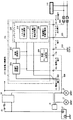
昼間走行用ライト点灯回路120は、図2に示すように、減光ユニット(減光・消灯手段、昼夜判別手段)121と、この減光ユニット121から引き出される複数の配線122〜126とを有する。
配線122は、減光ユニット121の電流入力端子t1から引き出され、キースイッチ16の下流側で電流供給線に接続される。
配線123は、減光ユニット121のアース端子t2から引き出され、車両10のボディに接続される。
配線124は、減光ユニット121のプラス出力端子t3から引き出され、昼間走行用ライト110のプラス配線に接続される。
配線125は、減光ユニット121のマイナス出力端子t4から引き出され、昼間走行用ライト110のマイナス配線に接続される。
更に、配線126は、減光ユニット121の信号入力端子t5から引き出され、ライティングスイッチ15の下流側でスモールランプ配線に接続される。
【0038】
減光ユニット121の内部回路121aは、図4に示すように、キースイッチ16と昼間走行用ライト110(〔LED〕あるいは〔放電灯及び有機発光体(光源)〕の点灯ユニットを有するset灯体)とを直列に接続するようにしてある(DC点灯)。このため、基本的に、キースイッチ16のON/OFFに応じて、昼間走行用ライト110を点灯/消灯させることができる。
これにより、ライティングスイッチ15を意識的に操作することなく、キースイッチ16の操作だけで昼間点灯を行うことが可能になる。その結果、昼間点灯のつけ忘れを防止できるとともに、消し忘れによるバッテリ17の放電を回避することができる。
【0039】
また、減光ユニット121は、信号入力端子がマイナス電圧のとき、つまり、ライティングスイッチ15がOFFポジションのとき、昼間走行用ライト110に規定の点灯電流を供給し、信号入力端子がプラス電圧のとき、つまり、ライティングスイッチ15が第一又は第二ポジションのとき、昼間走行用ライト110に規定値よりも低い減光用電流を供給する。
すなわち、ライティングスイッチ15が第一又は第二ポジションに操作される夜間走行においては、昼間走行用ライト110が減光状態で点灯される。これにより、夜間走行において、昼間走行用ライト110の光量が過剰になることを防止し、他の車両や歩行者にまぶしさを感じさせる不都合が回避できる。
【0040】
また、減光ユニット121は、スモールランプ13の点灯にもとづいて、夜間であると判定するので、簡単な回路構成で昼夜判別が可能になる。なお、減光ユニット121は、ヘッドライト12を減光制御するために構成された公知のものを利用することができる。
【0041】
つぎに、第一実施形態における車両用昼間点灯装置100の作用について、図5を参照して説明する。
同図に示すように、昼間走行用ライト110は、キースイッチ16がOFFのとき、ライティングスイッチ15のポジションに拘わらず、消灯する。一方、キースイッチ16がONのとき、ライティングスイッチ15がOFFポジションであれば、通常状態で点灯し、ライティングスイッチ15が第一又は第二ポジション(スモールランプ13又はヘッドライト12が点灯)であれば、減光状態で点灯する。
【0042】
以下、本発明の第二〜第六実施形態について、図面を参照して説明する。ただし、第一実施形態と共通の構成は、符号の百の位のみを変更し、その説明は省略する。
【0043】
[第二実施形態]
つぎに、本発明の第二実施形態について、図6及び図7を参照して説明する。図6は、第二実施形態における車両用昼間点灯装置の構成を示すブロック図、図7は、第二実施形態における車両用昼間点灯装置の作用を示す説明図である。
【0044】
図6に示すように、第二実施形態の車両用昼間点灯装置200は、減光ユニット221の信号入力端子から引き出される配線226の接続先が第一実施形態と相違する。
すなわち、配線226は、ライティングスイッチ15の下流側でヘッドライト配線に接続されている。
【0045】
これにより、昼間走行用ライト210は、図7に示すように、キースイッチ16がONのとき、ライティングスイッチ15がOFF又は第一ポジション(スモールランプ13が点灯)であれば、通常状態で点灯し、ライティングスイッチ15が第二ポジション(スモールランプ13及びヘッドライト12が点灯)であれば、減光状態で点灯する。
【0046】
[第三実施形態]
つぎに、本発明の第三実施形態について、図8及び図9を参照して説明する。図8は、第三実施形態における車両用昼間点灯装置の構成を示すブロック図、図9は、第三実施形態における車両用昼間点灯装置の作用を示す説明図である。
【0047】
図8に示すように、第三実施形態の車両用昼間点灯装置300は、第一実施形態の減光ユニット121に代えて、消灯ユニット321を備える点が第一実施形態と相違する。
すなわち、消灯ユニット321は、信号入力端子がマイナス電圧のとき、つまり、ライティングスイッチ15がOFFポジションのとき、昼間走行用ライト310に規定の点灯電流を供給し、信号入力端子がプラス電圧のとき、つまり、ライティングスイッチ15が第一又は第二ポジションのとき、昼間走行用ライト110への電流供給を遮断する。
【0048】
これにより、昼間走行用ライト310は、図9に示すように、キースイッチ16がONのとき、ライティングスイッチ15がOFFポジションであれば、通常状態で点灯し、ライティングスイッチ15が第一又は第二ポジション(スモールランプ13又はヘッドライト12が点灯)であれば、消灯する。
【0049】
[第四実施形態]
つぎに、本発明の第四実施形態について、図10及び図11を参照して説明する。図10は、第四実施形態における車両用昼間点灯装置の構成を示すブロック図、図11は、第四実施形態における車両用昼間点灯装置の作用を示す説明図である。
【0050】
図10に示すように、第四実施形態の車両用昼間点灯装置400は、消灯ユニット421の信号入力端子から引き出される配線426の接続先が第三実施形態と相違する。
すなわち、配線426は、ライティングスイッチ15の下流側でヘッドライト配線に接続されている。
【0051】
これにより、昼間走行用ライト410は、図11に示すように、キースイッチ16がONのとき、ライティングスイッチ15がOFF又は第一ポジション(スモールランプ13が点灯)であれば、通常状態で点灯し、ライティングスイッチ15が第二ポジション(スモールランプ13及びヘッドライト12が点灯)であれば、消灯する。
【0052】
[第五実施形態]
つぎに、本発明の第五実施形態について、図12及び図13を参照して説明する。図12は、第五実施形態における車両用昼間点灯装置の構成を示すブロック図、図13は、第五実施形態における車両用昼間点灯装置の作用を示す説明図である。
【0053】
図12に示すように、第五実施形態の車両用昼間点灯装置500は、第一実施形態の減光ユニット121に代えて、減光・消灯ユニット521を備える点が第一実施形態と相違する。
すなわち、減光・消灯ユニット521は、信号入力端子を二つ備えており、一方の端子入力に応じて昼間走行用ライト510を減光状態で点灯させ、他方の端子入力に応じて昼間走行用ライト510を消灯させるように構成される。
そして、減光用信号入力端子から引き出される配線526は、ライティングスイッチ15の下流側でスモールランプ配線に接続され、消灯用信号入力端子から引き出される配線527は、ライティングスイッチ15の下流側でヘッドライト配線に接続される。
【0054】
これにより、昼間走行用ライト510は、図13に示すように、キースイッチ16がONのとき、ライティングスイッチ15がOFFポジションであれば、通常状態で点灯し、ライティングスイッチ15が第一ポジション(スモールランプ13が点灯)であれば、減光状態で点灯し、ライティングスイッチ15が第二ポジション(スモールランプ13及びヘッドライト12が点灯)であれば、消灯する。
【0055】
なお、本発明は、前記各実施形態に限定されるものではなく、例えば、昼間走行用ライトの光源は、発光ダイオードに限らず、たとえば、放電灯などの各種の光源を用いることができる。
また、前記各実施形態では、キースイッチのON/OFFに応じて、昼間走行用ライトを点灯/消灯させるが、車両におけるエンジンの回転/停止に応じて、昼間走行用ライトを点灯/消灯させてもよい。その際には、エンジン回転検出手段として、オルタネータの発電信号を利用することができる。
【0056】
[第六実施形態]
つぎに、本発明の第六実施形態について、図14を参照して説明する。
同図は、本発明の車両用昼間点灯装置における昼間走行用ライト点灯回路の構成を示す回路構成図である。
【0057】
本実施形態は、第一実施形態と比較して、昼間走行用ライト点灯回路の構成が相違する。すなわち、第一実施形態では、昼間走行用ライトの点灯制御をDC(直流)で行なっていたのに対し、本実施形態では、その点灯制御をパルス波を用いて行う点で相違する。他の構成要素は第一実施形態と同様である。
したがって、図14において、図2と同様の構成部分については同一の符号を付して、その詳細な説明を省略する。
【0058】
図14に示すように、昼間走行用ライト点灯回路620は、減光ユニット(減光・消灯ユニット)621や複数の配線622〜626の他、供給電力制御部631を有している。
供給電力制御部631は、バッテリ17から昼間走行用ライト110へ供給される電圧や電流を制御する部分であって、定電圧回路部632と、発振回路部633と、発振コントロール回路部634と、スイッチングブロック635とを有している。
【0059】
ここで、定電圧回路部632は、バッテリ17から供給されてきた電圧を、所定の電圧値に変換し、この電圧値を保ちながら、発振回路部633へ供給する回路である。
この定電圧回路部632には、例えば、電圧値を変換するためのトランス(図示せず),ノイズをカットするフィルタ(図示せず),リップル分を低減する平滑回路(図示せず)などが含まれている。
【0060】
発振回路部633は、定電圧回路部632からの電圧にもとづいて、所定の周期と振幅とを有するパルス波を発振する回路である。
この発振回路部633には、たとえば、非正弦波発振回路であるマルチバイブレータやブロッキングオシレータなどを用いることができる。
なお、本実施形態においては、発振回路部633からの発振出力の波形はパルス波としているが、パルス波に限るものではなく、昼間走行用ライト110の点灯制御を可能とする波形であれば、たとえば、交流波(sine curve)の全波(あるいは半波)整流波形、鋸歯状波形、台形波形などであってもよい。
【0061】
発振コントロール回路部634は、発振回路部633から出力されるパルス波の振幅(duty)や周期(Hz)を制御する回路である。
つまり、発振コントロール回路部634は、スイッチングブロック635と同様、パルス波制御回路部としての機能を有している。
【0062】
スイッチングブロック635は、発振回路部633からのパルス波を昼間走行用ライト110へ供給するとともに、キースイッチ16のON/OFFにもとづいて、そのパルス波を供給/停止するパルス波制御回路部636を有している。
このパルス波形制御回路部636は、トランスやチョーク等を用いて電圧(あるいは、電流)の調整を行う。
【0063】
なお、このパルス波制御回路部636から昼間走行用ライト110へ供給される電圧(プラス出力端子t3における出力電圧)の波形は、図15に示すようになる。すなわち、供給電圧が“Vout”のとき、昼間走行用ライト110は点灯する。一方、供給電圧が“0”のとき、昼間走行用ライト110は消灯する。このため、同図に示すパルス波が供給されると、昼間走行用ライト110は、所定時間間隔で点灯・消灯を繰り返す。
【0064】
さらにスイッチングブロック635は、昼間走行用ライト110に供給する電圧又は電流として、バイアス電力(一定の電圧値を示すバイアス電圧、及び、一定の電流値を示すバイアス電流を含む)を出力するバイアス電力供給回路部637と、バイアス電圧又はバイアス電流の示す値よりも超過する分の電圧又は電流の周期制御を行う超過電力制御回路部638とを有している。
バイアス電力供給回路部637は、バッテリ17からの直流電圧(あるいは直流電流)を、超過電力制御回路部638を介して昼間走行用ライト110へ供給する。なお、バイアス電力供給回路部637は、バッテリ17からの直流電圧(あるいは直流電流)に代えて、発振回路部633からのパルス波を直流波形に整流して直流電圧とすることもできる。
【0065】
超過電力制御回路部638は、バイアス電力供給回路部637からの直流電圧(あるいは直流電流)に、発振回路部633からのパルス波を加算して、昼間走行用ライト110へ供給する。
つまり、超過電力制御回路部638は、直流電圧にパルス波を加算したときは“Vout”の値を示す電圧を出力し、直流電圧にパルス波を加算しないときはバイアス電圧“Vb”の値を示す電圧を出力し、昼間走行用ライト110を点灯させないときは電圧を出力しない(出力電圧は“0”〔V〕)。
【0066】
なお、超過電力制御回路部638から昼間走行用ライト110へ供給される電圧(プラス出力端子t3における電圧)の波形は、図16に示すようになる。すなわち、昼間走行用ライト110に供給される電圧が“Vout”のとき、昼間走行用ライト110は強い光で点灯する。これに対し、供給電圧がバイアス電圧“Vb”のとき、昼間走行用ライト110は弱い光で点灯する。そして、供給電圧が出力されないとき(“0”のとき)、昼間走行用ライト110は消灯する。
【0067】
ただし、バイアス制御を行なわない場合は、バイアス電力供給回路部637や超過電力制御回路部638は、設けなくてもよい。
また、以上の説明においては主に電圧を制御して昼間走行用ライト110の明るさ等を調整することとしていたが、電圧ではなく電流によっても同様に調整可能である。
【0068】
さらに、スイッチングブロック635のパルス波制御回路部636や超過電力制御回路部638においては、パルス波の周期の他、振幅を制御することもできる。この振幅の制御は、例えば、トランジスタなどを用いた増幅回路等によって実現可能である。
そして、振幅の変化量は、車両の周囲の明るさにもとづいて定めることができる。この場合、昼間走行用ライト点灯回路620には、その車両の周囲の明るさを検知するための明度検知装置(例えば、フォトダイオードやフォトトランジスタなど、図示せず)や、この明度検知装置からの信号にもとづきパルス波の振幅の変化量を設定してパルス波制御回路部636や超過電力制御回路部638へ伝える変化量設定部(図示せず)などが設けられる。
このようにパルス波の振幅を制御することで、昼間走行用ライト110の明るさを調整できる。
【0069】
なお、昼間走行用ライト110の点滅時間間隔や明るさの調整、つまりパルス波の周期や振幅の調整は、その車両の運転者が行うような構成とすることもできる。
この場合、昼間走行用ライト点灯回路620には、運転者によって操作される調整操作部(例えば、調整つまみや調整スライドなど、図示せず)と、この調整操作部の変位量に応じてパルス波の周期や振幅を変化させる調整制御部(図示せず)とが設けられる。
なお、この調整制御部には、例えば、パルス波の周期を調整するためのコンバータ回路や、その振幅を調整するための増幅回路などを設けることができる。
【0070】
昼間走行用ライトへ供給される電圧(あるいは電流)の周期や振幅を制御する供給電力制御部を昼間走行用ライト点灯回路に設けることにより、昼間走行用ライトを所定時間間隔で点滅させることができる。
したがって、自己の車両で昼間に昼間走行用ライトを点滅させることで、他者に対し自分の車両の存在を迅速かつ確実に認識させることが可能となる。
【0071】
さらに、供給電力制御部にバイアス電力供給回路部や超過電力制御回路部を設けることにより、点灯している昼間走行用ライトの明るさが常時一定以上確保されるため、他者に対し自分の車両の存在を確実に認識させることができ、さらに、その昼間走行用ライトの明るさを周囲の明るさに応じて調整可能とすることで、その他者による認識をより確実なものとすることができる。
【0072】
[第七実施形態]
つぎに、本発明の第七実施形態について、図17を参照して説明する。
同図は、本発明の車両用昼間点灯装置における昼間走行用ライトの構成を示す正面構成図である。
【0073】
本実施形態は、第一実施形態と比較して、昼間走行用ライトの構成が相違する。すなわち、第一実施形態では、昼間走行用ライトの光源がすべて同一色であったのに対し、本実施形態では、その光源が複数の異なる色で構成されている点で相違する。他の構成要素は第一実施形態と同様である。
したがって、図17において、図2と同様の構成部分については同一の符号を付して、その詳細な説明を省略する。
【0074】
図17に示すように、昼間走行用ライト110は、色の異なる複数の光源(発光ダイオード112)を有している。
この光源(発光ダイオード112)は、色1(例えば、赤色)に発光する発光ダイオード112aと、色2(例えば、黄色)に発光する発光ダイオード112bとの組み合わせによって構成できる。
【0075】
なお、同図においては、昼間走行用ライト110の有する光源が発光可能な色を2色としているが、2色に限るものではなく、3色以上であってもよい。
また、各色の配置は、同図においては、昼間走行用ライト110の向かって左半分に色a、右半分に色bで配置しているが、これらの配置に限るものではなく、たとえば、上半分と下半分との配置などであってもよい。
さらに、光源に用いられる色は、赤色や黄色に限るものではなく、たとえば、白色,青色,橙色,緑色など様々な色を用いることができる。
【0076】
この昼間走行用ライト110の有する各光源は、昼間走行用ライト点灯回路620のスイッチングブロック635の制御により、それぞれ同一又は異なるタイミングで点灯することができる。
さらに、各光源は、スイッチングブロック635の制御により、それぞれ交互に点滅させることもできる。
【0077】
昼間走行用ライトに色の異なる複数の光源を設け、各光源の発光タイミングを異ならせることにより、車両の運転手や通行人等が、その昼間走行用ライトに注目しやすくなる。
したがって、昼間においても昼間走行用ライトを点灯させることで、他者に対し自分の車両の存在を迅速かつ確実に認識させることが可能となる。
【0078】
【発明の効果】
以上のように、本発明によれば、車両(四輪車)において、キースイッチの操作だけで昼間点灯を行うことが可能になるため、昼間点灯のつけ忘れを防止できるとともに、消し忘れによるバッテリの放電を回避することができる。
【0079】
また、車両に昼間走行用ライトを付設するので、その明るさや向きを昼間点灯用に最適化することが可能になり、その結果、ヘッドライトを利用して昼間点灯を行う場合に比べ、良好な視認性を発揮することができる。
【0080】
また、昼間走行用ライトの光源を発光ダイオードで構成した場合は、ハロゲンランプなどの白熱球を光源にする場合に比べ、消費電力を大幅に削減できるばかりでなく、消費電力の削減に伴い、燃費も向上させることができる。
【0081】
さらに、昼間走行用ライト点灯回路が、昼間走行用ライトへ供給される電圧や電流を制御するため、昼間点灯に適した明るさで昼間走行用ライトを点灯させることができ、これにより、他者に対し、自分の車両の存在を迅速かつ確実に認識させることが可能となる。
【図面の簡単な説明】
【図1】本発明の車両用昼間点灯装置が設けられた車両の正面図である。
【図2】第一実施形態における車両用昼間点灯装置の構成を示すブロック図である。
【図3】ライティングスイッチの制御内容を示す説明図である。
【図4】昼間走行用ライトに直流電圧を印加する場合の回路構成を示すブロック図である。
【図5】第一実施形態における車両用昼間点灯装置の作用を示す説明図である。
【図6】第二実施形態における車両用昼間点灯装置の構成を示すブロック図である。
【図7】第二実施形態における車両用昼間点灯装置の作用を示す説明図である。
【図8】第三実施形態における車両用昼間点灯装置の構成を示すブロック図である。
【図9】第三実施形態における車両用昼間点灯装置の作用を示す説明図である。
【図10】第四実施形態における車両用昼間点灯装置の構成を示すブロック図である。
【図11】第四実施形態における車両用昼間点灯装置の作用を示す説明図である。
【図12】第五実施形態における車両用昼間点灯装置の構成を示すブロック図である。
【図13】第五実施形態における車両用昼間点灯装置の作用を示す説明図である。
【図14】第六実施形態における車両用昼間点灯装置の構成を示すブロック図である。
【図15】パルス波により昼間走行用ライトに電圧を印加するときの供給電力制御部の出力波形を示す波形図である。
【図16】直流電圧にパルス波を加算した電圧を昼間走行用ライトに印加するときの供給電力制御部の出力波形を示す波形図である。
【図17】第七実施形態における昼間走行用ライトの構成例を示す正面構成図である。
【符号の説明】
10 車両
12 ヘッドライト
13 スモールランプ
15 ライティングスイッチ
16 キースイッチ
100 車両用昼間点灯装置
110 昼間走行用ライト
112 発光ダイオード
112a 発光ダイオード(色1)
112b 発光ダイオード(色2)
120 昼間走行用ライト点灯回路
121 減光ユニット
200 車両用昼間点灯装置
210 昼間走行用ライト
221 減光ユニット
226 配線
300 車両用昼間点灯装置
400 車両用昼間点灯装置
421 消灯ユニット
500 車両用昼間点灯装置
521 減光・消灯ユニット
631 供給電力制御部
632 定電圧回路部
633 発振回路部
634 発振コントロール回路部
635 スイッチングブロック
636 パルス波制御回路部
637 バイアス電力供給回路部
638 超過電力制御回路部[0001]
TECHNICAL FIELD OF THE INVENTION
The present invention relates to a daytime lighting device for a vehicle that emphasizes the presence of a vehicle by daylighting, and more particularly to a daytime lighting device for a vehicle attached to a four-wheeled vehicle (automobile).
[0002]
[Prior art]
To prevent the occurrence of accidents when driving a vehicle, one must not only accurately recognize the presence of another person (other vehicles or pedestrians), but also reliably recognize the presence of the vehicle that he or she drives. It is important to let them.
In nighttime driving, the presence of the vehicle is emphasized by turning on the headlights, so that mutual recognition is easy, but in daytime driving, the vehicle is visually recognized only by natural light, so mutual recognition may occur depending on the situation. May run out.
[0003]
In recent years, attention has been paid to the effect of the headlights to be visually recognized, and it has been encouraged to turn on the headlights even during daytime running. In motorcycles, constant lighting of headlights (lighting during daytime) has already been generalized.
On the other hand, even for four-wheeled vehicles, some companies (transportation companies, taxi companies, etc.) turn on their headlights during the day, and their accident prevention effects have been reported.
[0004]
Heretofore, various techniques regarding lighting control of a vehicle headlight have been proposed.
For example, by providing an inverter that converts DC from an on-board battery into AC and adding means for adding the DC from the battery and the AC from the inverter, the brightness is increased and the life is not shortened. There has been proposed a technique of turning on a headlight including an incandescent lamp or the like (for example, see Patent Document 1).
[0005]
[Patent Document 1]
Patent No. 3080620
[0006]
[Problems to be solved by the invention]
However, in the conventional four-wheeled vehicle, the headlight is turned on / off regardless of the ON / OFF of the key switch (engine key). It is necessary to perform a proper lighting operation and to turn off the lighting switch when getting off the vehicle. For this reason, the headlight may be forgotten to be turned on, and the battery may be discharged by forgetting to turn off the headlight.
[0007]
In addition, since the brightness and direction of the headlight are set based on nighttime lighting, there is a problem that good visibility cannot be exhibited in daytime lighting.
[0008]
In addition, since incandescent bulbs such as halogen lamps are usually used as the light source of the headlight, turning on the headlight in the daytime not only shortens the life of the light source but also increases the power consumption of the battery. There are inconveniences such as shortened service life and reduced fuel consumption.
[0009]
Further, for example, when a new light different from the headlight is provided on the front of the vehicle body and is turned on, it is necessary that the lighting of the new light be quickly and reliably recognized by others. Was.
However, in the daytime, the surroundings were bright enough only with natural light, and human eyes were used to the brightness. For this reason, simply turning on a light having a weak light amount outdoors in the daytime may be masked by the surrounding brightness, and the lighting may be difficult to recognize.
[0010]
The present invention has been made in view of the above circumstances, and prevents forgetting to turn on the light during the day, avoids discharging the battery due to forgetting to turn off the light, and achieves better visibility compared to lighting during the day with headlights. An object of the present invention is to provide a daytime lighting device for a vehicle that can be used to promptly and reliably recognize the presence of the vehicle of another person.
[0011]
[Means for Solving the Problems]
To achieve the above object, a vehicle daytime lighting device of the present invention is attached to a vehicle, and a daytime running light that emphasizes the presence of the vehicle by lighting the vehicle, and a key switch on / off of the vehicle, or A daytime running light lighting circuit for turning on / off the daytime running light according to rotation / stop of an engine in the vehicle.
[0012]
If the vehicle daytime lighting device is configured as described above, daylighting can be performed only by operating the key switch without intentionally operating the lighting switch as in the related art. As a result, it is possible to prevent forgetting to turn on the light in the daytime and to avoid discharging the battery due to forgetting to turn off the light.
In addition, since the vehicle is equipped with daytime running lights, its brightness and direction can be optimized for daytime lighting, and as a result, compared to the case where headlights are used for daytime lighting, better lighting and direction can be achieved. Visibility can be exhibited.
[0013]
In the daytime lighting device for a vehicle according to the present invention, a light source of the daytime running light is formed of a light emitting diode.
With such a configuration of the daytime lighting device for a vehicle, the power consumption can be significantly reduced (1/50 to 1/100) as compared with a case where an incandescent bulb such as a halogen lamp is used as a light source, and also the power consumption is reduced. With the reduction in fuel consumption, fuel efficiency can be improved. For example, even if one vehicle saves 1 liter / month in fuel consumption due to improved fuel efficiency, in Japan, which has about 70 million four-wheeled vehicles, about 70 million liters / month of fuel is consumed. Can be saved.
[0014]
The daytime lighting device for a vehicle according to the present invention may be configured such that the daytime running light lighting circuit automatically turns on the daytime running light when the daytime determining unit determines that the daytime is at night. It has a dimming / extinguishing means for dimming or extinguishing light.
With such a configuration of the vehicle daytime lighting device, in the nighttime running, the light amount of the daytime running light is prevented from being excessive, and the inconvenience of causing other vehicles or pedestrians to feel glare is avoided. .
[0015]
In the daytime lighting device for a vehicle according to the present invention, the day / night determining means determines that the time is nighttime based on lighting of a headlight or a small lamp provided in the vehicle.
If the daytime lighting device for a vehicle has such a configuration, day and night can be determined with a simple circuit configuration, and cost can be reduced.
[0016]
Further, the daytime lighting device for a vehicle according to the present invention is configured such that the daytime running lights are symmetrically arranged at predetermined intervals at a front portion of the vehicle in a pair.
With such a configuration of the daytime lighting device for a vehicle, it is possible to easily recognize the vehicle width and the inter-vehicle distance as compared with the case where the daytime running lights are arranged asymmetrically.
[0017]
Further, in the daytime lighting device for a vehicle according to the present invention, the daytime running light is arranged near and below the headlight.
With such a configuration of the vehicle daytime lighting device, the visibility of the daytime running light can be improved, and even if the daytime running light and the headlight are simultaneously turned on, there is no discomfort.
[0018]
The daytime lighting device for a vehicle according to the present invention is configured such that the daytime running light lighting circuit includes a supply power control unit that controls a voltage and / or a current supplied to the daytime running light.
With such a configuration of the vehicle daytime lighting device, it is possible to control the voltage and current supplied to the daytime running light, so that it is possible to adjust the brightness, blinking interval, and the like of the daytime running light.
As a result, the daytime running light can be turned on at a brightness or a blinking interval suitable for daytime lighting, and therefore, it is possible to promptly and surely recognize the existence of the own vehicle to another person.
[0019]
In the daytime lighting device for a vehicle according to the present invention, the supply power control unit may output the voltage and / or the current as a pulse wave, and the cycle and / or the amplitude of the pulse wave output from the oscillation circuit unit. And a pulse wave control circuit for controlling the pulse wave control circuit.
With such a configuration of the vehicle daytime lighting device, the period of the pulse wave can be controlled to blink the daytime running light. As a result, the driver of the vehicle can call attention to a driver of another vehicle, a pedestrian, or the like.
[0020]
Further, by controlling the cycle and amplitude of the pulse wave, the blinking interval and brightness of the daytime running light can be adjusted. This also allows the driver of the vehicle to make another person aware of the presence of his or her vehicle and call attention.
In addition, by making it possible to realize the blinking time and brightness according to the traveling state, the surrounding situation, and the like, it is possible to reliably recognize the own vehicle by other vehicles and the like.
[0021]
In the daytime lighting device for a vehicle according to the present invention, the supply power control unit may include a bias power supply circuit unit that outputs a voltage and / or current having a constant value as power for the bias supplied to the daytime running light. And an excess power control circuit for controlling the cycle of the voltage and / or current exceeding the predetermined value and supplying the cycle-controlled voltage and / or current to the daytime running lights. .
[0022]
With such a configuration of the vehicle daytime lighting device, the brightness of the daytime running light can be made brighter or darker while the brightness of the daytime running light is maintained at a certain level or more. As a result, the presence of the vehicle can be reliably notified to the other person, and the attention of the other person can be alerted.
Further, by adjusting the brightness of the daytime running lights according to the surrounding brightness, it is possible to ensure that others recognize the own vehicle.
The daytime lighting device for a vehicle according to the present invention is a device for turning on a light in the daytime. Even in the daytime, for example, the sunshine day and the weak day, the outdoor and the premises, the morning and evening and the daytime, etc. When compared, the surrounding brightness is different. On the other hand, the human eye adjusts the amount of light to be taken in according to the surrounding brightness. From this, for example, even if the same person sees the same light in a plurality of places with different surrounding brightness (or in a time zone with different surrounding brightness), for example, the brightness of the light recognized by the person is different. The degree of each will vary.
Therefore, by maintaining the brightness of the lit daytime running lights at a certain level or more, the minimum brightness that allows others to recognize the presence of their own vehicle is secured, and further, the daytime running lights are further improved. Can be adjusted according to the brightness of the surroundings, so that recognition by others can be made more reliable in any surrounding situation.
[0023]
In the daytime lighting device for a vehicle according to the present invention, the excess power control circuit unit controls a cycle of a voltage and / or a current exceeding a predetermined value, and controls the cycle-controlled voltage and / or current. It is configured to add to a voltage and / or current indicating a constant value received from the bias power supply circuit unit and supply the added voltage and / or current to the daytime running light.
[0024]
If the daytime lighting device for a vehicle has such a configuration, the bias power (voltage or current indicating a constant value) output from the bias power supply circuit unit is applied to the power (voltage or voltage) cycle-controlled by the excess power control circuit unit. Current) can be supplied to a daytime running light.
For this reason, a daytime running light can maintain its brightness over a certain level by bias power, and its brightness can be made brighter or darker by cycle-controlled power. it can.
By turning on the daytime running lights capable of controlling the brightness, a driver or a pedestrian of another vehicle can quickly turn on the daytime running lights whose brightness changes while maintaining a constant light quantity. Can be found. Therefore, the driver of the vehicle that turns on the daytime running light can surely notify the other person of the existence of his / her vehicle and call attention of the other person.
[0025]
In the daytime lighting device for a vehicle according to the present invention, the daytime running light includes a plurality of light sources having different colors.
With such a configuration of the vehicle daytime lighting device, the daytime running light can emit light in a plurality of colors instead of a single color. For this reason, for example, by emitting light in a color that draws attention, such as red or yellow, it is possible to promptly and securely recognize the presence of the vehicle of another person.
[0026]
Further, in the daytime lighting device for a vehicle according to the present invention, the supply power control unit may light the plurality of light sources at the same or different timings.
With such a configuration of the vehicle daytime lighting device, the daytime running light can emit light of different colors at various timings, instead of continuously emitting light at a constant brightness.
Thus, the driver, the pedestrian, and the like of the vehicle can easily find the daytime running light whose emission color changes, and can reliably recognize the presence of the vehicle.
[0027]
In the daytime lighting device for a vehicle according to the present invention, the power supply control unit may be configured to alternately blink the plurality of light sources.
If the vehicle daytime lighting device is configured as described above, in the daytime running light, for example, red and yellow alternately flash, so that others can draw attention to their own vehicle. it can. Therefore, the other person can quickly and surely recognize the presence of the vehicle that turns on the daytime running light.
[0028]
BEST MODE FOR CARRYING OUT THE INVENTION
Hereinafter, embodiments of the present invention will be described with reference to the drawings.
[First embodiment]
First, a first embodiment of the present invention will be described with reference to FIGS. FIG. 1 is a front view of a vehicle provided with a vehicle daylighting device of the present invention, FIGS. 2 and 4 are block diagrams showing a configuration of the vehicle daylighting device according to the first embodiment, and FIG. FIG. 5 is an explanatory diagram showing the control contents of the switch, and FIG. 5 is an explanatory diagram showing the operation of the daytime lighting device for a vehicle in the first embodiment.
[0029]
The
Each of these
[0030]
As shown in FIG. 2, the
For example, as shown in FIG. 3, when the
The left and right direction indicator lamps 14 are selectively turned on and off in response to operation of a direction indicator lever (not shown) provided in the vehicle.
[0031]
Further, as shown in FIG. 2, the
When the engine is started, the
[0032]
The
[0033]
As shown in FIG. 2, the vehicle
The light emitting diode 112 is, for example, a high-brightness white light emitting diode, and can be lit with extremely low power consumption as compared with an incandescent bulb such as a halogen lamp.
[0034]
As shown in FIG. 1, the
[0035]
As shown in FIG. 1, the
[0036]
The
[0037]
As shown in FIG. 2, the daytime running
The wiring 122 is drawn out from the current input terminal t1 of the
The wiring 123 is drawn out from the ground terminal t2 of the
The
The
Further, the wiring 126 is drawn out from the signal input terminal t5 of the
[0038]
As shown in FIG. 4, the internal circuit 121a of the
This makes it possible to perform daytime lighting only by operating the
[0039]
Further, the
That is, during night driving in which the
[0040]
Further, the
[0041]
Next, the operation of the vehicle
As shown in the figure, the
[0042]
Hereinafter, second to sixth embodiments of the present invention will be described with reference to the drawings. However, in the configuration common to the first embodiment, only the hundreds digit is changed, and the description is omitted.
[0043]
[Second embodiment]
Next, a second embodiment of the present invention will be described with reference to FIGS. FIG. 6 is a block diagram illustrating a configuration of a daytime lighting device for a vehicle according to the second embodiment, and FIG. 7 is an explanatory diagram illustrating an operation of the daytime lighting device for a vehicle according to the second embodiment.
[0044]
As shown in FIG. 6, the vehicle
That is, the
[0045]
As a result, the
[0046]
[Third embodiment]
Next, a third embodiment of the present invention will be described with reference to FIGS. FIG. 8 is a block diagram illustrating a configuration of a vehicle daytime lighting device according to the third embodiment, and FIG. 9 is an explanatory diagram illustrating an operation of the vehicle daylighting device according to the third embodiment.
[0047]
As shown in FIG. 8, the vehicle daytime lighting device 300 of the third embodiment is different from the first embodiment in that a light-off unit 321 is provided instead of the
That is, the light-off unit 321 supplies a specified lighting current to the daytime running light 310 when the signal input terminal is at a negative voltage, that is, when the
[0048]
Accordingly, the daytime running light 310 is lit in the normal state when the
[0049]
[Fourth embodiment]
Next, a fourth embodiment of the present invention will be described with reference to FIGS. FIG. 10 is a block diagram illustrating a configuration of a vehicle daylighting device according to the fourth embodiment, and FIG. 11 is an explanatory diagram illustrating an operation of the vehicle daylighting device according to the fourth embodiment.
[0050]
As shown in FIG. 10, the vehicle
That is, the
[0051]
As a result, the
[0052]
[Fifth embodiment]
Next, a fifth embodiment of the present invention will be described with reference to FIGS. FIG. 12 is a block diagram illustrating a configuration of a daytime lighting device for a vehicle according to a fifth embodiment, and FIG. 13 is an explanatory diagram illustrating an operation of the daytime lighting device for a vehicle according to the fifth embodiment.
[0053]
As shown in FIG. 12, the vehicle
That is, the dimming / extinguishing unit 521 has two signal input terminals, and turns on the daytime running light 510 in a dimmed state according to one terminal input, and turns on or off during the daytime according to the other terminal input. The light 510 is configured to be turned off.
The wiring 526 drawn from the signal input terminal for dimming is connected to the small lamp wiring on the downstream side of the
[0054]
Accordingly, the
[0055]
The present invention is not limited to the above embodiments. For example, the light source of the daytime running light is not limited to a light emitting diode, and various light sources such as a discharge lamp can be used.
In the above embodiments, the daytime running light is turned on / off according to the ON / OFF of the key switch. However, the daytime running light is turned on / off according to the rotation / stop of the engine in the vehicle. Is also good. In that case, the power generation signal of the alternator can be used as the engine rotation detecting means.
[0056]
[Sixth embodiment]
Next, a sixth embodiment of the present invention will be described with reference to FIG.
FIG. 1 is a circuit diagram showing a configuration of a daytime running light lighting circuit in a vehicle daylighting device of the present invention.
[0057]
This embodiment differs from the first embodiment in the configuration of the daytime running light lighting circuit. That is, in the first embodiment, the lighting control of the daytime running light is performed by DC (direct current), whereas in the present embodiment, the lighting control is performed by using a pulse wave. Other components are the same as in the first embodiment.
Therefore, in FIG. 14, the same components as those in FIG. 2 are denoted by the same reference numerals, and detailed description thereof will be omitted.
[0058]
As shown in FIG. 14, the daytime running light lighting circuit 620 includes a supply power control unit 631 in addition to a dimming unit (dimming / extinguishing unit) 621 and a plurality of wirings 622 to 626.
The supply power control unit 631 controls the voltage and current supplied from the
[0059]
Here, the constant
The constant
[0060]
The
As the
In the present embodiment, the waveform of the oscillation output from the
[0061]
The oscillation
That is, the oscillation
[0062]
The
The pulse
[0063]
The waveform of the voltage (output voltage at the plus output terminal t3) supplied from the pulse wave
[0064]
Further, the
The bias power
[0065]
The excess power
That is, the excess power
[0066]
The waveform of the voltage (the voltage at the plus output terminal t3) supplied from the excess power
[0067]
However, when the bias control is not performed, the bias
In the above description, the voltage is mainly controlled to adjust the brightness and the like of the
[0068]
Further, in the pulse
The amount of change in the amplitude can be determined based on the brightness around the vehicle. In this case, the daytime running light lighting circuit 620 includes a lightness detection device (for example, a photodiode or a phototransistor, not shown) for detecting the brightness around the vehicle, or a light detection device from the lightness detection device. A change amount setting unit (not shown) for setting a change amount of the amplitude of the pulse wave based on the signal and transmitting the change amount to the pulse wave
By controlling the amplitude of the pulse wave in this way, the brightness of the daytime running light 110 can be adjusted.
[0069]
The adjustment of the blinking time interval and the brightness of the
In this case, the daytime running light lighting circuit 620 includes an adjustment operation unit (for example, an adjustment knob or an adjustment slide, not shown) operated by the driver, and a pulse wave according to a displacement amount of the adjustment operation unit. And an adjustment control unit (not shown) for changing the period and amplitude of the control signal.
The adjustment control unit may include, for example, a converter circuit for adjusting the cycle of the pulse wave, an amplifier circuit for adjusting the amplitude thereof, and the like.
[0070]
By providing a supply power control unit for controlling the cycle and amplitude of the voltage (or current) supplied to the daytime running light in the daytime running light lighting circuit, the daytime running light can be blinked at predetermined time intervals. .
Therefore, by flashing the daytime running lights in the daytime of the own vehicle, it is possible to promptly and reliably recognize the existence of the own vehicle to other people.
[0071]
In addition, by providing the bias power supply circuit section and the excess power control circuit section in the supply power control section, the brightness of the lit daytime running lights is always kept at a certain level or more, so that the vehicle can be controlled by other people. Can be reliably recognized, and the brightness of the daytime running light can be adjusted according to the surrounding brightness, so that the recognition by others can be made more reliable. .
[0072]
[Seventh embodiment]
Next, a seventh embodiment of the present invention will be described with reference to FIG.
FIG. 1 is a front view showing the configuration of a daytime running light in the vehicle daylighting device of the present invention.
[0073]
This embodiment differs from the first embodiment in the configuration of the daytime running light. That is, in the first embodiment, the light sources of the daytime running lights are all the same color, whereas in the present embodiment, the light source is configured with a plurality of different colors. Other components are the same as in the first embodiment.
Therefore, in FIG. 17, the same components as those in FIG. 2 are denoted by the same reference numerals, and detailed description thereof will be omitted.
[0074]
As shown in FIG. 17, the
This light source (light emitting diode 112) can be configured by a combination of a light emitting diode 112a emitting light of color 1 (for example, red) and a light emitting diode 112b emitting light of color 2 (for example, yellow).
[0075]
In FIG. 1, the light emitted by the light source of the
In addition, in the figure, the arrangement of each color is such that a color a is arranged in a left half toward the
Further, the color used for the light source is not limited to red or yellow, and various colors such as white, blue, orange, and green can be used.
[0076]
Each light source of the daytime running light 110 can be turned on at the same or different timing under the control of the
Furthermore, each light source can also be turned on and off alternately under the control of the
[0077]
By providing a plurality of light sources having different colors in the daytime lights and making the light emission timings of the respective light sources different, it becomes easy for a driver or a pedestrian of the vehicle to pay attention to the daytime lights.
Therefore, even in the daytime, by turning on the daytime running lights, it becomes possible to promptly and surely recognize the existence of the own vehicle to others.
[0078]
【The invention's effect】
As described above, according to the present invention, in a vehicle (four-wheeled vehicle), it is possible to perform daylighting only by operating a key switch. Can be avoided.
[0079]
In addition, since the vehicle is equipped with daytime running lights, it is possible to optimize the brightness and direction for daytime lighting, and as a result, compared to the case where headlights are used for daytime lighting, better lighting and orientation can be achieved. Visibility can be exhibited.
[0080]
In addition, when the light source of the daytime running light is composed of light emitting diodes, not only can the power consumption be significantly reduced compared to the case where an incandescent bulb such as a halogen lamp is used as the light source, Can also be improved.
[0081]
Furthermore, the daytime running light lighting circuit controls the voltage and current supplied to the daytime running light, so that the daytime running light can be turned on at a brightness suitable for daytime lighting. However, it is possible to promptly and reliably recognize the presence of the vehicle.
[Brief description of the drawings]
FIG. 1 is a front view of a vehicle provided with a vehicle daytime lighting device of the present invention.
FIG. 2 is a block diagram illustrating a configuration of a daytime lighting device for a vehicle according to the first embodiment.
FIG. 3 is an explanatory diagram showing control contents of a lighting switch.
FIG. 4 is a block diagram showing a circuit configuration when a DC voltage is applied to a daytime running light.
FIG. 5 is an explanatory diagram showing the operation of the vehicle daytime lighting device in the first embodiment.
FIG. 6 is a block diagram illustrating a configuration of a daytime lighting device for a vehicle according to a second embodiment.
FIG. 7 is an explanatory diagram showing an operation of the vehicle daytime lighting device in the second embodiment.
FIG. 8 is a block diagram illustrating a configuration of a daytime lighting device for a vehicle according to a third embodiment.
FIG. 9 is an explanatory diagram illustrating the operation of the daytime lighting device for a vehicle according to the third embodiment.
FIG. 10 is a block diagram illustrating a configuration of a daytime lighting device for a vehicle according to a fourth embodiment.
FIG. 11 is an explanatory diagram showing an operation of the vehicle daytime lighting device in the fourth embodiment.
FIG. 12 is a block diagram illustrating a configuration of a daytime lighting device for a vehicle according to a fifth embodiment.
FIG. 13 is an explanatory view showing the operation of the daytime lighting device for a vehicle in the fifth embodiment.
FIG. 14 is a block diagram illustrating a configuration of a daytime lighting device for a vehicle according to a sixth embodiment.
FIG. 15 is a waveform diagram showing an output waveform of a supply power control unit when a voltage is applied to a daytime running light by a pulse wave.
FIG. 16 is a waveform diagram showing an output waveform of a supply power control unit when a voltage obtained by adding a pulse wave to a DC voltage is applied to a daytime running light.
FIG. 17 is a front configuration diagram illustrating a configuration example of a daytime running light according to a seventh embodiment.
[Explanation of symbols]
10 vehicles
12 Headlight
13 Small lamp
15 Lighting switch
16 key switch
100 Daytime lighting device for vehicles
110 Daytime running light
112 light emitting diode
112a light emitting diode (color 1)
112b light emitting diode (color 2)
120 Lighting circuit for daytime running lights
121 dim unit
200 Daylighting device for vehicles
210 Daytime running light
221 dim unit
226 Wiring
300 Daytime lighting system for vehicles
400 Daytime lighting device for vehicles
421 Unlit unit
500 Daytime lighting system for vehicles
521 dim / extinguish unit
631 supply power control unit
632 constant voltage circuit
633 Oscillation circuit section
634 Oscillation control circuit
635 switching block
636 pulse wave control circuit
637 Bias power supply circuit
638 Excess power control circuit
Claims (13)
前記車両におけるキースイッチのON/OFF、又は、前記車両におけるエンジンの回転/停止に応じて、前記昼間走行用ライトを点灯/消灯させる昼間走行用ライト点灯回路とを有する
ことを特徴とする車両用昼間点灯装置。A daytime running light attached to the vehicle, the lighting of which emphasizes the presence of the vehicle;
A daytime running light lighting circuit for turning on / off the daytime running light in accordance with ON / OFF of a key switch in the vehicle or rotation / stop of an engine in the vehicle. Daytime lighting device.
昼夜を判別する昼夜判別手段と、
この昼夜判別手段が夜間であると判定したとき、前記昼間走行用ライトを自動的に減光又は消灯させる減光・消灯手段とを有する
ことを特徴とする請求項1又は2記載の車両用昼間点灯装置。The daytime running light lighting circuit,
Day / night determining means for determining day / night;
3. The daytime vehicle according to claim 1, further comprising: a dimming / extinguishing unit that automatically dims or extinguishes the daytime running light when the day / night determining unit determines that it is nighttime. Lighting device.
前記昼間走行用ライトへ供給される電圧及び/又は電流を制御する供給電力制御部を有した
ことを特徴とする請求項1〜6のいずれかに記載の車両用昼間点灯装置。The daytime running light lighting circuit,
The daytime lighting device for a vehicle according to any one of claims 1 to 6, further comprising a supply power control unit that controls a voltage and / or a current supplied to the daytime running light.
前記電圧及び/又は電流をパルス波として出力する発振回路部と、
この発振回路部から出力されるパルス波の周期及び/又は振幅を制御するパルス波制御回路部とを有した
ことを特徴とする請求項7記載の車両用昼間点灯装置。The supply power control unit,
An oscillation circuit unit that outputs the voltage and / or current as a pulse wave;
8. The daytime lighting device for a vehicle according to claim 7, further comprising a pulse wave control circuit unit for controlling a cycle and / or an amplitude of a pulse wave output from the oscillation circuit unit.
前記昼間走行用ライトへ供給されるバイアス分の電力として、一定値を示す電圧及び/又は電流を出力するバイアス電力供給回路部と、
前記一定値を超過する分の前記電圧及び/又は電流について、前記周期を制御して、この周期制御した電圧及び/又は電流を前記昼間走行用ライトへ供給する超過電力制御回路部とを有した
ことを特徴とする請求項7又は8記載の車両用昼間点灯装置。The supply power control unit,
A bias power supply circuit unit that outputs a voltage and / or current showing a constant value as power for the bias supplied to the daytime running light;
An excess power control circuit unit that controls the cycle for the voltage and / or current that exceeds the fixed value and supplies the cycle-controlled voltage and / or current to the daytime running light. The daytime lighting device for a vehicle according to claim 7 or 8, wherein:
前記一定値を超過する分の前記電圧及び/又は電流について、前記周期を制御して、この周期制御した電圧及び/又は電流を、前記バイアス電力供給回路部から受けた前記一定値を示す電圧及び/又は電流に加算して、前記昼間走行用ライトへ供給する
ことを特徴とする請求項9記載の車両用昼間点灯装置。The excess power control circuit section,
For the voltage and / or current that exceeds the fixed value, the cycle is controlled, and the cycle-controlled voltage and / or current is applied to the voltage and / or current indicating the fixed value received from the bias power supply circuit unit. The daytime lighting device for a vehicle according to claim 9, wherein the daytime lighting device is supplied to the daytime running light by adding to a current.
ことを特徴とする請求項1〜10のいずれかに記載の車両用昼間点灯装置。The daytime lighting device for a vehicle according to any one of claims 1 to 10, wherein the daytime running light includes a plurality of light sources having different colors.
ことを特徴とする請求項11記載の車両用昼間点灯装置。The daytime lighting device for a vehicle according to claim 11, wherein the supply power control unit turns on the plurality of light sources at the same or different timings.
ことを特徴とする請求項11又は12記載の車両用昼間点灯装置。The daytime lighting device for a vehicle according to claim 11, wherein the supply power control unit causes the plurality of light sources to blink alternately, respectively.
Priority Applications (1)
| Application Number | Priority Date | Filing Date | Title |
|---|---|---|---|
| JP2003016424A JP2004051080A (en) | 2002-05-31 | 2003-01-24 | Daytime lighting device for vehicle |
Applications Claiming Priority (2)
| Application Number | Priority Date | Filing Date | Title |
|---|---|---|---|
| JP2002160313 | 2002-05-31 | ||
| JP2003016424A JP2004051080A (en) | 2002-05-31 | 2003-01-24 | Daytime lighting device for vehicle |
Publications (2)
| Publication Number | Publication Date |
|---|---|
| JP2004051080A true JP2004051080A (en) | 2004-02-19 |
| JP2004051080A5 JP2004051080A5 (en) | 2005-09-22 |
Family
ID=31949192
Family Applications (1)
| Application Number | Title | Priority Date | Filing Date |
|---|---|---|---|
| JP2003016424A Pending JP2004051080A (en) | 2002-05-31 | 2003-01-24 | Daytime lighting device for vehicle |
Country Status (1)
| Country | Link |
|---|---|
| JP (1) | JP2004051080A (en) |
Cited By (8)
| Publication number | Priority date | Publication date | Assignee | Title |
|---|---|---|---|---|
| JP2006202754A (en) * | 2005-01-21 | 2006-08-03 | Valeo Vision | Optical module for lighting device for automobile, designed to provide at least one main cut-off beam |
| JP2009161104A (en) * | 2008-01-09 | 2009-07-23 | Autonetworks Technologies Ltd | Load control circuit and battery exhaustion preventive method |
| JP2013256211A (en) * | 2012-06-13 | 2013-12-26 | Piaa Corp | Lighting device for vehicle |
| JP2014080143A (en) * | 2012-10-18 | 2014-05-08 | Koito Mfg Co Ltd | Lighting-control system for vehicular lamp |
| CN105346437A (en) * | 2015-10-21 | 2016-02-24 | 安徽江淮汽车股份有限公司 | Control circuit of daytime running lamps |
| EP3196071A1 (en) * | 2015-12-18 | 2017-07-26 | Charles I. Sassoon | Led headlamp with daytime running lamp |
| KR101795078B1 (en) | 2012-11-28 | 2017-11-07 | 현대자동차주식회사 | Compulsion drive method of four wheel drive mode |
| WO2018021063A1 (en) * | 2016-07-29 | 2018-02-01 | 株式会社小糸製作所 | Vehicle lighting system, vehicle system, and vehicle |
-
2003
- 2003-01-24 JP JP2003016424A patent/JP2004051080A/en active Pending
Cited By (16)
| Publication number | Priority date | Publication date | Assignee | Title |
|---|---|---|---|---|
| JP2006202754A (en) * | 2005-01-21 | 2006-08-03 | Valeo Vision | Optical module for lighting device for automobile, designed to provide at least one main cut-off beam |
| JP2009161104A (en) * | 2008-01-09 | 2009-07-23 | Autonetworks Technologies Ltd | Load control circuit and battery exhaustion preventive method |
| JP2013256211A (en) * | 2012-06-13 | 2013-12-26 | Piaa Corp | Lighting device for vehicle |
| JP2014080143A (en) * | 2012-10-18 | 2014-05-08 | Koito Mfg Co Ltd | Lighting-control system for vehicular lamp |
| KR101795078B1 (en) | 2012-11-28 | 2017-11-07 | 현대자동차주식회사 | Compulsion drive method of four wheel drive mode |
| CN105346437A (en) * | 2015-10-21 | 2016-02-24 | 安徽江淮汽车股份有限公司 | Control circuit of daytime running lamps |
| US10076992B2 (en) | 2015-12-18 | 2018-09-18 | Charles I. Sassoon | LED headlamp with daytime running lamp |
| EP3196071A1 (en) * | 2015-12-18 | 2017-07-26 | Charles I. Sassoon | Led headlamp with daytime running lamp |
| US10220763B2 (en) | 2015-12-18 | 2019-03-05 | Charles I. Sassoon | LED headlamp with daytime running lamp |
| US10647244B2 (en) | 2015-12-18 | 2020-05-12 | Charles I. Sassoon | LED headlamp with daytime running lamp |
| EP3702214A1 (en) * | 2015-12-18 | 2020-09-02 | Charles I. Sassoon | Led headlamp with daytime running lamp |
| US11351911B2 (en) | 2015-12-18 | 2022-06-07 | Charles I. Sassoon | LED headlamp with daytime running lamp |
| WO2018021063A1 (en) * | 2016-07-29 | 2018-02-01 | 株式会社小糸製作所 | Vehicle lighting system, vehicle system, and vehicle |
| JPWO2018021063A1 (en) * | 2016-07-29 | 2019-05-09 | 株式会社小糸製作所 | Vehicle lighting system, vehicle system and vehicle |
| US10676023B2 (en) | 2016-07-29 | 2020-06-09 | Koito Manufacturing Co., Ltd. | Vehicle lighting system, vehicle system, and vehicle |
| JP7045993B2 (en) | 2016-07-29 | 2022-04-01 | 株式会社小糸製作所 | Vehicle lighting systems, vehicle systems and vehicles |
Similar Documents
| Publication | Publication Date | Title |
|---|---|---|
| TW200819341A (en) | Bicycle illumination apparatus | |
| JP5434615B2 (en) | Headlamp emission color control device | |
| JP2004051080A (en) | Daytime lighting device for vehicle | |
| US10057957B2 (en) | Vehicle light | |
| JP4754081B2 (en) | Bicycle lighting device | |
| US7928660B2 (en) | Vehicular conspicuity lamp with rapidly modulated intensity | |
| JP2003212171A (en) | Lighting device for bicycle | |
| JP2014125015A (en) | Bicycle equipped with electric motor | |
| WO2005005194A1 (en) | Daytime lighting unit for vehicle | |
| JP2008201154A (en) | On-vehicle led unit drive circuit | |
| JP2004259582A (en) | Lamp control circuit and lamp control method | |
| KR0128694B1 (en) | Driving lamp on/off apparauts | |
| JP4922063B2 (en) | Vehicle foot lighting device | |
| JP2002305091A (en) | Lighting unit | |
| CN203523838U (en) | Traffic safety vest | |
| JP2004314818A (en) | Vehicle indication lamp lighting device | |
| JP2004228385A (en) | Automobile instrument lighting circuit | |
| CN216600137U (en) | Color-changeable double-needle car lamp | |
| CN211457468U (en) | Vehicle lamp control system | |
| JP6980343B2 (en) | Lighting control device and traffic light of signal lamp | |
| JP2002370575A (en) | Electric door mirror lighting system | |
| KR101967673B1 (en) | Safety tripod which can be powered by mibile phone | |
| JP3251656B2 (en) | Railroad crossing signal light | |
| JP2003011868A (en) | Lighting system for bicycle | |
| KR960003455Y1 (en) | Small lamp & brake lamp for controlling filament light by transformation |
Legal Events
| Date | Code | Title | Description |
|---|---|---|---|
| A521 | Written amendment |
Free format text: JAPANESE INTERMEDIATE CODE: A523 Effective date: 20050408 |
|
| A871 | Explanation of circumstances concerning accelerated examination |
Free format text: JAPANESE INTERMEDIATE CODE: A871 Effective date: 20050408 |
|
| A975 | Report on accelerated examination |
Free format text: JAPANESE INTERMEDIATE CODE: A971005 Effective date: 20050613 |
|
| A131 | Notification of reasons for refusal |
Free format text: JAPANESE INTERMEDIATE CODE: A131 Effective date: 20050621 |
|
| A02 | Decision of refusal |
Free format text: JAPANESE INTERMEDIATE CODE: A02 Effective date: 20051018 |