JP2004048219A - Inserting method of electronic watermark information - Google Patents
Inserting method of electronic watermark information Download PDFInfo
- Publication number
- JP2004048219A JP2004048219A JP2002200741A JP2002200741A JP2004048219A JP 2004048219 A JP2004048219 A JP 2004048219A JP 2002200741 A JP2002200741 A JP 2002200741A JP 2002200741 A JP2002200741 A JP 2002200741A JP 2004048219 A JP2004048219 A JP 2004048219A
- Authority
- JP
- Japan
- Prior art keywords
- information
- image
- motion detection
- compression
- frame
- Prior art date
- Legal status (The legal status is an assumption and is not a legal conclusion. Google has not performed a legal analysis and makes no representation as to the accuracy of the status listed.)
- Pending
Links
Images


Classifications
-
- G—PHYSICS
- G06—COMPUTING; CALCULATING OR COUNTING
- G06T—IMAGE DATA PROCESSING OR GENERATION, IN GENERAL
- G06T1/00—General purpose image data processing
- G06T1/0021—Image watermarking
- G06T1/0085—Time domain based watermarking, e.g. watermarks spread over several images
-
- G—PHYSICS
- G06—COMPUTING; CALCULATING OR COUNTING
- G06T—IMAGE DATA PROCESSING OR GENERATION, IN GENERAL
- G06T2201/00—General purpose image data processing
- G06T2201/005—Image watermarking
- G06T2201/0051—Embedding of the watermark in the spatial domain
-
- G—PHYSICS
- G06—COMPUTING; CALCULATING OR COUNTING
- G06T—IMAGE DATA PROCESSING OR GENERATION, IN GENERAL
- G06T2201/00—General purpose image data processing
- G06T2201/005—Image watermarking
- G06T2201/0053—Embedding of the watermark in the coding stream, possibly without decoding; Embedding of the watermark in the compressed domain
-
- G—PHYSICS
- G06—COMPUTING; CALCULATING OR COUNTING
- G06T—IMAGE DATA PROCESSING OR GENERATION, IN GENERAL
- G06T2201/00—General purpose image data processing
- G06T2201/005—Image watermarking
- G06T2201/0061—Embedding of the watermark in each block of the image, e.g. segmented watermarking
Abstract
Description
【0001】
【発明の属する技術分野】
本発明は情報埋込み方法または装置に関し、特に、ディジタル化された情報に他の情報を埋め込むための方法または装置に関する。
【0002】
【従来の技術】
近年、画像や音楽などのコンテンツがディジタル化され、記憶媒体あるいは通信媒体を介して流通されるようになってきた。このようなディジタル化されたコンテンツ情報の著作権を保護するために、コンテンツ情報に人間の視聴覚では気付かない程度の変更を加える方法でコピー制御情報や著作権情報などの他の情報を埋め込むことによって、データ処理装置を利用したコンテンツ情報のコピー回数の制限、あるいは不正コピーされたコンテンツ情報から著作権者の特定を可能にする電子透かし技術が重要視されている。
【0003】
電子透かし技術の実用化には、次の2つの要求を満たす必要がある。
(1) コンテンツ情報の劣化の抑制:
例えば、コンテンツが静止画あるいは動画である場合に、これら画像のデータを対象とした電子透かし情報の埋め込みにおいて、画像に加えた変更がコンテンツの鑑賞の妨げないようにすること。すなわち、コンテンツ情報の一部に加えた変更が人間の視聴覚には目立たないこと。
(2) 耐久性の向上:
画像処理や音声処理を加えても埋め込み情報、すなわち、コンテンツ情報に加えた変更が劣化し難いこと。
【0004】
上記条件を満たすためには、コンテンツの性質に応じて、コンテンツの変更個所と、変更の程度あるいは強度を最適化する必要がある。以下、コンテンツ情報として代表的な画像を例にして、従来の電子透かし技術を分析する。
【0005】
画像データの場合、一般に、画像の状態変化が比較的平坦な領域や輪郭部分では、画素(ピクセル)の状態値(輝度あるいは色)に不適切な変更を加えると、変更箇所に不自然さが目立つ。しかしながら、被写体の画素値の変動の激しい乱雑部分では画素に比較的大きな変更を加えても人間の目には目立たないと言う性質がある。この性質に着目して、例えば、IEEE Trans. Consumer Electronics, Vol.45, No.4, pp. 1150−1158, (1999).には、透かし情報を埋め込むべき画像フレームの輝度変動を分析することによって被写体の乱雑部分を特定し、画素値の変更が目立ちにくい上記乱雑部分では大きな変更を加え、画素値の変更が目立ち易い輪郭部分や平坦部分には変更を加えないか、加えるとしても変更の程度を小さくする電子透かし技術が提案されている。
【0006】
【発明が解決しようとする課題】
電子透かし情報の埋め込み対象は、静止画像に限られず、動画も対象となる。動画データは、時系列的に配列された複数の静止画フレームから構成されており、動画の鑑賞中にフレームの送りを止めることによって、個々のフレームを静止画として鑑賞する場合がある。
【0007】
このため、動画を対象とした電子透かし情報の埋込みにおいては、画素値の変更個所が静止画状態でも動画状態でも目立たないようにする必要がある。例えば、特開2000−175019号公報(対応ヨーロッパ特許公開公報EP1006730A2)は、静止画としての性質と動画としての性質の両方を考慮して、変更画素と変更程度を最適化する技術を開示している。具体的には、時系列的に配列された複数の静止画フレームからなる動画データに透かし情報を埋め込む場合に、着目フレーム中の各画像ブロック毎に動きベクトルと変動量(動画的性質)を検出し、動き量に応じて、各ブロック毎の画素変更率の指定規則を選択し、各ブロック内の画像の状態(静止画的性質)によって決まる輝度変更許容画素のうちから上記規則で指定された個数の画素を選択して、透かし情報となる輝度の変更処理を施す。
【0008】
しかしながら、動画の性質を考慮するためには、着目フレーム中の各画像ブロック毎に動きベクトルと変動量(動画的性質)を検出する必要がある。これは計算量が多く非常に時間のかかる処理であり、出来るだけ高速で透かし挿入を行うことが望まれている。
【0009】
【課題を解決するための手段】
動画をコンテンツとして流通させる場合は通常、ハードウェアまたはソフトウェアにより実装されるMPEG(Moving Picture Expert Group)やその他の動画圧縮技術を用いた圧縮処理を行っており、これら圧縮処理中においても、動きベクトルと変動量(動画的性質)の検出処理を行なっている。
【0010】
本発明は、透かし情報の埋め込み対象となるコンテンツ情報が備える動画としての性質を考慮して変更個所と変更強度を最適化するために必要な動きベクトルと変動量を検出する処理をMPEG等の圧縮処理と共用することで、一連の処理の負荷を減らす技術を提供する。
【0011】
本発明による情報埋込み方法の第一の形態は、コンテンツを構成するフレームに含まれるブロックについて、他のフレームと比較して動きベクトルと変動量を求める第一ステップと、第一ステップで求めた動きベクトルと変動量を利用して、上記フレームのいずれかに情報を埋め込む第二ステップと、第一ステップで求めた動きベクトルと変動量を利用して、情報を埋め込んだ上記フレームからなるコンテンツを圧縮する第三ステップとを有し、コンテンツに電子透かしを挿入することを特徴とする。
【0012】
本発明による情報埋込み方法の第二の形態は、圧縮されたコンテンツを構成するフレームに含まれるブロックについて、動きベクトルと変動量を抽出する第一ステップと、上記圧縮されたコンテンツを、情報を埋め込み可能な状態まで伸長して、第一ステップで抽出した動きベクトルと変動量を利用して、上記情報を埋め込み可能な状態になったフレームのいずれかに情報を埋め込む第二ステップと、第一ステップで抽出した動きベクトルと変動量を利用して、情報を埋め込んだ上記フレームからなるコンテンツを圧縮する第三ステップとを有し、圧縮されたコンテンツに電子透かしを挿入することを特徴とする。
【0013】
本発明による情報埋込み方法の第三の形態は、コンテンツを構成するフレームに含まれるブロックについて、他のフレームと比較して動きベクトルと変動量を求める第一ステップと、第一ステップで求めた動きベクトルと変動量を利用して上記コンテンツを圧縮する第二ステップと、第二ステップで求めた圧縮したコンテンツを、情報を埋め込み可能な状態にして、第一ステップで求めた動きベクトルと変動量を利用して、上記情報を埋め込み可能な状態になったフレームのいずれかに情報を埋め込む第三ステップと、第一ステップで求めた動きベクトルと変動量を利用して、情報を埋め込んだ上記フレームからなるコンテンツを圧縮する第四ステップとを有し、コンテンツに電子透かしを挿入することを特徴とする。
【0014】
実際の応用においては、埋め込み対象となるコンテンツ情報のその他の性質として、例えば、各静止画フレーム内あるいは各画像ブロック内の輝度の変動を考慮すればよい。
【0015】
また、別形態において、第一ステップで圧縮コンテンツから動きベクトルと変動量を求めるには、例えば、MPEG等の圧縮がされていて、ブロックマッチング法が用いられている場合は、その動きベクトルと変動量をそのまま用いる。
【0016】
【発明の実施の形態】
本発明の実施例を図1〜図10を参照して説明する。なお、以下の各図面において、同じ機能を備える構成要素には同じ番号を付与している。
【0017】
本実施例では、コンテンツ情報として動画を考える。動画データは時系列的な複数の静止画フレームから構成されており、各静止画フレームの画素の一部に変更を加えることによって、動画に透かし情報を埋め込むことができる。以下に述べる実施例では、各静止画フレームから選ばれた特定の画素に対して、人間の目に違和感を与えない範囲で輝度を変更する。
【0018】
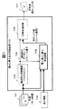
図1は、第一の実施例における透かし挿入及び圧縮処理の原理を説明するための図である。図1に示すように、透かし情報を挿入する前の動画データである原画101及び挿入情報102を入力として、透かし挿入及び圧縮処理装置103において、透かし情報を挿入した動画データである透かし入り画107を生成する。
【0019】
透かし挿入及び圧縮処理装置103内部では、まず最初に動き検出処理装置104において、原画101を入力として、原画を構成する異なるフレーム間の動き検出処理により、フレーム毎の動きベクトルvと変動量dを求める。以下、フレーム番号と動きベクトルvと変動量dを動き検出データ108と総称する。ここで、動き検出処理には、例えばブロックマッチング法など用いられる。
【0020】
次に電子透かし挿入処理装置105において、原画101及び各フレーム毎の動き検出データ108を入力として、上記動き検出データ108を求める元となったフレームのいずれかに対して透かし入り画を生成する。圧縮処理装置106においては、動き検出データ108及び透かし入り画を入力として、圧縮後透かし入り画107を生成する。
【0021】
図2は、図1で示した電子透かし挿入及び圧縮処理装置103の概略構成図であり、CPU201と、ROM202と、入力装置203と、出力装置204と、通信装置205と、メモリ206とを有している。CPU201は、電子透かし挿入及び圧縮処理装置103全体の動作を制御する装置である。メモリ206は、電子透かし挿入及び圧縮処理装置103全体の動作を制御する際に、その為の各種処理プログラムや画像データなどのデータを格納する記憶装置である。入力装置203は、DVD、CD−ROM、HDDなどの記録媒体上や有線や無線などの通信媒体上の画像データ及び挿入情報の入力を行う装置である。出力装置204は、受信した画像データの映像出力を行う装置である。当該画像データに音声データが付加されている場合には、音声出力も行う。通信装置205は、インターネットやイントラネットなどのネットワーク、または、SCSIやRS422などの専用信号線を介して他の処理装置との通信および制御を行う装置である。
【0022】
電子透かし挿入及び圧縮処理装置103は、動き検出処理装置104と、電子透かし挿入処理装置105と圧縮処理装置106をLSIチップ上に実装された回路として、制御処理部209をメモリ206上に展開されたプログラムとして有する。また、電子透かし挿入及び圧縮処理装置103は、入力された原画像データや圧縮前後の透かし入り画を格納する画像データ格納領域207と、動き検出処理装置104により出力された動き検出データ108を格納する動き検出データ格納領域208をメモリ206内に有する。また、各処理装置104、105、106は、制御処理部209と同様に、メモリ206上に展開されたプログラムにより実現されてもよい。
【0023】
各プログラムはCPU201により実行されるものである。また、各プログラムの一部または全部は、可搬の記憶媒体から、または、他のサーバから通信媒体を介して、電子透かし挿入及び圧縮処理装置103に導入されるものであっても良い。
【0024】
制御処理209は、入力装置203により受信された画像データの全部または一部分及び挿入情報を上記画像データ格納領域207に処理可能な状態で格納する。
【0025】
動き検出処理装置104は、メモリ206上に展開した画像データに対して、フレーム間の動き検出処理を行い、動き検出データ108を求め、メモリ206上の動き検出データ格納領域へ出力する処理を行う。または、上記動き検出データを透かし挿入処理装置105及び圧縮処理装置106へ逐次的に出力するようにしても良い。
【0026】
電子透かし挿入処理装置105は、メモリ上に展開された原画に対し、挿入情報及び動き検出データ及び原画より求めた静止画的の性質を用いて、透かし情報の挿入処理を行いメモリ上へ透かし入り画を出力する。
【0027】
圧縮処理装置106は、上記動き検出データを用い、上記透かし入り画に対し、圧縮処理を行いメモリ上へ圧縮後透かし入り画を出力する。
【0028】
制御処理部209は、圧縮処理装置105が出力した圧縮後透かし入り画を、出力装置203へ出力したり、通信装置205を経由して外部の機器に対しての圧縮後透かし入り画を出力したりする処理を行う。
【0029】
図2に示すように、本実施例において、104、105、106の各処理部、処理装置は、メモリ206上のプログラムとして展開されている場合は、耐タンパ領域に格納されることが望ましい。上記電子透かし挿入及び圧縮処理装置103がPCのようにユーザが比較的容易にプログラムをインストールできる装置である場合に、OSとOS上のアプリケーションの汎用的な機能を利用した受信機能などによって、画像データの受信をおこなった場合にも、上記耐タンパ領域に格納された各処理部を経由して画像データのアクセスが行われるものとする。
【0030】
図3は、電子透かし挿入及び圧縮処理装置103の処理手順を示すフローチャートである。
【0031】
ステップ301で制御処理部209は、入力装置203を介して全てまたは一部の原画像データをメモリ206内の画像データ格納領域207に一時的に格納する。
【0032】
ステップ302で制御処理部209は、入力装置203を介して入力された全てまたは一部の原画像データのうち、透かし情報の埋め込み対象として着目中の各静止画(以下、着目フレームという)を所定のサイズ、例えば、16画素×8画素(=128画素)の複数の画像ブロックに分割し、当該画像データを103内のメモリ206内の画像データ格納領域207に格納する。
【0033】
ステップ303で動き検出処理装置104は、上記ブロック毎に、時間軸上でKフレーム離れたフレーム(以下、参照フレームという)と比較し、上記着目フレーム中に含まれる被写体の動きを検出する。この動き検出処理は、図3で詳述するように、上記ブロック毎に動きベクトルと変動量を求める。着目フレームと参照フレームとの間のフレーム間隔を示すパラメータKの値(例えば、K=4)は、圧縮アルゴリズム等に依存し利用者により決定される。
【0034】
ここで必要とする動き検出は、例えば、a review and new contribution, Proc. IEEE, Vol.83, No.6, pp. 858−876, (1998).に示される公知の技術により実現できる。動き検出の結果は、動きベクトルと変動量で表される。動き検出については、図9を用いて後述する。
【0035】
ステップ304で制御処理部209は、着目フレームにおいて、全ブロックの動き検出処理がされたかどうか判別し、まだの場合は次のブロックにおいてステップ303の処理を行う。
【0036】
ステップ305で電子透かし挿入処理装置105は、着目フレームに含まれる静止画像を分析し、画像ピクセル毎の変更容易度を求めた後、ブロック毎に求めた上記動き検出データを用い、着目フレームの各ピクセル毎もしくはブロック毎の変更量を決定し、画素値を変更することで透かしの挿入処理を行う。挿入処理を施した透かし入り画は画像データ格納領域207に格納する。
【0037】
なお、参照フレームに対して透かしの挿入処理を行なうように構成してもよい。
【0038】
例えば、上記動画を構成する各静止画フレームが720×480画素からなる場合、これを16×8画素単位に分割すると、1フレームが45×60(=2700)個のブロックに分割される。上記フレームに埋め込む透かし情報を6ビット情報(数値0〜63で表される64種類の文字コード)とした場合、各ビットに450個のブロックを割り当てることができる。
【0039】
1つのフレームを構成する上記2700個のブロックをN個の文字コードと対応したNグループに分け、各グループ内において、2700/N個のブロックを上記6ビット情報に割り当てると、1ビット当り450/N個のブロックを割り当てることができる。
【0040】
透かし情報を構成するビットパターンの各ビットを静止画フレーム内の互いに離散した位置関係にある複数の画像ブロックと予め対応付けておき、例えば、あるビット位置にビット情報”1”を書き込む場合は、上記ビット位置と対応した複数の画像ブロックにおいて、輝度を上記ピクセル毎の変更量だけ明るくし、ビット情報”0”を書きこむ場合は、輝度を上記ピクセル毎の変更量だけ暗くすることによって、各フレームにN個の文字コードを透かし情報として埋め込むことができる。
【0041】
フレーム内の画像の状態によっては、輝度の変更が許されないブロックもでてくるが、各ビットにフレーム内で互いに離散した位置関係にある複数の画像ブロックを割り当てておけば、確率的に少なくとも1つのブロックで輝度変更が可能となり、透かし情報を確実に挿入することができる。
【0042】
上述した画像ブロックとビット情報との対応関係は、透かし情報が与えられた時点で予めテーブル化してメモリ206に記憶しておき、電子透かし挿入処理装置105がメモリ206を参照することによって各ブロック毎の書き込み情報を判断できるようにしておく。
【0043】
尚、透かし情報は、上記6ビット情報に代えて8ビット情報を適用してもよい。また、上述したように各ビットと画像ブロックとを対応付ける代わりに、例えば、上記6ビット情報で表記できる64種類の各文字コードと画像ブロックとを対応づけておき、文字コードの有無によって対応する画像ブロックの画素状態を変化させるようにしてもよい。各画素の輝度状態が、例えば、0〜127の128段階ある場合、変更箇所として指定された各画素について、輝度の段階を指定量だけ変更する代わりに、各画素の輝度変更は1段階に固定して、輝度変更する画素数を上記指定量に応じて可変にするようにしてもよい。
【0044】
ステップ306で圧縮処理装置106は、ステップ303で求めた動き検出データを用い、画像データ格納領域207に格納された透かし入り画に対し圧縮処理を行い、圧縮後の透かし入り画を画像データ格納領域207に格納する。ここで、圧縮処理として、例えばMPEG圧縮の場合は、DCT変換を行ったり、DCT係数の量子化を行ったり、可逆圧縮を行ったりする。
【0045】
ステップ307で制御処理部209は、全フレームに対し上記の処理がされたかどうか判別し、まだの場合は引き続き次のフレームにおいて302からの処理を再開する。
【0046】
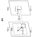
図9は、代表的な動き検出処理であるブロックマッチング法の原理について説明した図である。ブロックマッチング法は、MPEGのマクロブロック(16×16ピクセル)毎に動きベクトルを推定する代表的な動き検出手法である。具体的な手順は以下の通りである。第一に、着目フレーム画像Y(t)内のマクロブロックと上記ブロック位置から(k, l)だけずれた参照フレームY(t’)内のマクロブロックとの差分和D(k, l)を求める。差分和Dは、i, j=0〜15の範囲で、
|Y(t)bx+i,by+j−Y(t’)bx+k+i,by+l+j|
の絶対値の和を取ったものである。但し、(bx, by)は、マクロブロックの始点を表すピクセル位置である。第二に、算出した差分和D(k, l)をk, lの探索範囲内(−15≦k, l≦15が一般的)に渡って算出する。すなわち、31×31個の差分和が生成される。第三に、31×31個の差分和Dの中で、最小のものdを求め変化量dとし、その時のベクトルvを動きベクトルvとする。
【0047】
図10は、MPEG圧縮時に動き検出(ブロックマッチング法)をするときの着目フレームと参照フレームについて説明した図である。MPEG圧縮時に各フレームは、フレーム内の情報のみで圧縮を行うIフレームと、過去のフレームからフレーム間予測を行うPフレームと、過去及び未来のフレームからフレーム間予測を行うBフレームの3つに分類される。ここで、図中の矢印は、動き検出時に比較を行っている2つのフレームを表し、矢印の元は着目フレームであり、矢印の先は参照フレームである。
【0048】
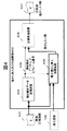
図4は、第二の実施例における透かし挿入及び圧縮処理の原理を説明するための図である。図4に示すように、圧縮された原画401及び挿入情報102を入力として、透かし挿入及び圧縮処理装置403において、圧縮された透かし入り画107を生成する。
【0049】
透かし挿入及び圧縮処理装置403内部では、最初に動き検出処理装置404において、MPEG等により圧縮された原画401を入力として動き検出データ取得装置により、動き検出データ108を取得する。次に電子透かし挿入処理装置405において、原画401及び動き検出データ108を入力として、透かし入り画を生成する。ここで、電子透かし挿入装置405は、圧縮画像401を完全に伸長するのではなく、透かしが挿入が可能な状態まで伸長する。そして、挿入情報102にあわせて、画像の画素値(例えば、RGB値、輝度値、色情報など)やDCT変換を行った後のDCT係数を指定量だけ上げ下げすることで透かし入り画を作成する。
【0050】
圧縮処理装置406は、動き検出データ108及び405で生成した透かし入り画を入力とした再圧縮を行ない、圧縮後透かし入り画107を生成する。
【0051】
図5は、第三の実施例における透かし挿入及び圧縮処理の原理を説明するための図である。第三の実施例では、第一、第二の実施例とは異なり、透かし挿入装置と圧縮装置が分離してある。
【0052】
図5に示すように、最初に透かし挿入装置503において、原画101及び挿入情報102を入力として、動き検出データ108と透かし入り画507を生成する。
【0053】
透かし挿入装置503内部では、原画101を入力として動き検出処理装置504により、動き検出データ108を求める。次に電子透かし挿入処理装置505において、原画101及び動き検出データ108を入力として、透かし入り画507を生成する。
【0054】
圧縮装置508では、生成された動き検出データ108と透かし入り画507を入力として、圧縮装置109において、圧縮後透かし入り画107を生成する。
【0055】
図6は、図5で示した透かし挿入装置503及び圧縮処理装置508の概略構成図である。図6に示すように、透かし挿入装置503及び圧縮処理装置508は、CPU201と、ROM202と、入力装置203と、出力装置204と、通信装置205と、メモリ206とを有している。
【0056】
透かし挿入装置503及び圧縮処理装置508は、入力装置203や出力装置204や通信装置205を用いて、画像データや動き検出データや挿入情報などをやりとり可能とする。
【0057】
透かし挿入装置503は、動き検出処理装置104と電子透かし挿入処理装置105をLSIチップ上に実装された回路として、制御処理部209をメモリ206上に展開されたプログラムとして有する。また、透かし挿入装置503は、入力された画像データや圧縮前後の透かし入り画を格納する画像データ格納領域207と、動き検出処理装置104により出力された動き検出データ108を格納する動き検出データ格納領域208をメモリ206内に有する。
【0058】
圧縮処理装置508は、圧縮処理装置106をLSIチップ上に実装された回路として、制御処理部209をメモリ206上に展開されたプログラムとして有する。また、圧縮処理装置508は、入力された画像データや圧縮前後の透かし入り画を格納する画像データ格納領域207と、入力された動き検出データ108を格納する動き検出データ格納領域208をメモリ206内に有する。
【0059】
上記透かし挿入装置503及び圧縮処理装置508がPCのようにユーザが比較的容易にプログラムをインストールできる装置である場合に、OSとOS上のアプリケーションの汎用的な機能を利用した受信機能などによって、画像データの受信をおこなった場合にも、上記耐タンパ領域に格納された各処理部を経由して画像データのアクセスが行われるものとする。
【0060】
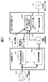
図7は、第四の実施例における透かし挿入処理及び圧縮処理の原理を説明するための図である。第四の実施例では、第三の実施例と同様、透かし挿入及び圧縮装置708と圧縮装置703が分離してある。
【0061】
図7に示すように、まず最初に圧縮装置703において、原画101及び挿入情報102を入力として、動き検出データ108と圧縮後透かし入り画107を生成する。圧縮装置703内部では、原画101を入力として動き検出処理装置104により、動き検出データ108を求め、次に圧縮処理装置105において、原画101及び動き検出データ108を入力として、圧縮後原画401を生成する。
【0062】
次に、透かし挿入装置708において、圧縮装置703によって生成された動き検出データ108と透かし入り画401を入力として、圧縮後透かし入り画107を生成する。透かし挿入装置708内部では、最初に電子透かし挿入処理装置405において、動き検出データ108と圧縮後原画401と挿入情報102を入力として、透かし入り画を生成する。次に、圧縮処理装置406において、動き検出データ108と生成された透かし入り画401を入力として、圧縮後透かし入り画107を生成する。
【0063】
図8は、図7で示した圧縮装置703及び透かし挿入装置708の概略構成図である。
【0064】
図8に示すように、圧縮装置703及び透かし挿入装置708は、CPU201と、ROM202と、入力装置203と、出力装置204と、通信装置205と、メモリ206とを有している。圧縮装置703及び透かし挿入装置708は、入力装置203や出力装置204や通信装置205を用いて、画像データや動き検出データや挿入情報などのやりとりを行う。
【0065】
圧縮装置703は、動き検出処理装置104と圧縮処理装置106をLSIチップ上に実装された回路として、制御処理部209をメモリ206上に展開されたプログラムとして有する。また、圧縮装置703は、入力された画像データや圧縮前後の透かし入り画を格納する画像データ格納領域207と、入力された動き検出データ108を格納する動き検出データ格納領域208をメモリ206内に有する。
【0066】
透かし挿入装置708は、電子透かし挿入処理装置405と圧縮処理装置406をLSIチップ上に実装された回路として、制御処理部209をメモリ206上に展開されたプログラムとして有する。また、透かし挿入装置708は、入力された画像データや圧縮前後の透かし入り画を格納する画像データ格納領域207と、動き検出処理装置104により出力された動き検出データ108を格納する動き検出データ格納領域208をメモリ206内に有する。
【0067】
上記透かし圧縮装置703及び透かし挿入装置708がPCのようにユーザが比較的容易にプログラムをインストールできる装置である場合に、OSとOS上のアプリケーションの汎用的な機能を利用した受信機能などによって、画像データの受信をおこなった場合にも、上記耐タンパ領域に格納された各処理部を経由して画像データのアクセスが行われるものとする。
【0068】
上述したように、本実施例では、本来圧縮処理に必要な動き検出データを電子透かし挿入処理に利用することで、動画と静止画の両方の性質を反映させて透かし挿入可能とし、画質劣化を抑制し情報の耐性を向上した高速な透かし情報の埋め込みが可能となる。
【0069】
【発明の効果】
本発明によれば、高速な透かし情報の埋め込みが可能となる。
【図面の簡単な説明】
【図1】透かし挿入及び圧縮処理の原理を説明するための図。
【図2】電子透かし挿入及び圧縮処理装置103の概略構成図。
【図3】電子透かし挿入及び圧縮処理装置103の処理手順を示すフローチャート。
【図4】第二の実施例における透かし挿入及び圧縮処理の原理を説明するための図。
【図5】第三の実施例における透かし挿入及び圧縮処理の原理を説明するための図。
【図6】第三の実施例における透かし挿入装置503及び圧縮処理装置508の概略構成図。
【図7】第四の実施例における透かし挿入及び圧縮処理の原理を説明するための図。
【図8】第四の実施例における圧縮装置703及び透かし挿入装置708の概略構成図。
【図9】代表的な動き検出処理であるブロックマッチング法の原理について説明した図。
【図10】圧縮時の動き検出において使用する着目フレームと参照フレームについて説明した図。
【符号の説明】
101…原画(フレーム画像)、102…挿入情報、103…透かし挿入及び圧縮装置、104…動き検出処理装置(ブロックマッチング)、105…電子透かし挿入処理装置、106…圧縮処理装置、107…圧縮後透かし入り画、108…動き検出データ。[0001]
TECHNICAL FIELD OF THE INVENTION
The present invention relates to an information embedding method or apparatus, and more particularly, to a method or apparatus for embedding other information in digitized information.
[0002]
[Prior art]
In recent years, content such as images and music has been digitized and distributed via storage media or communication media. In order to protect the copyright of such digitized content information, by embedding other information such as copy control information and copyright information in such a way that the content information is changed so as not to be noticed by human audiovisual information. A digital watermarking technique that allows the number of copies of content information to be copied using a data processing device, or the identification of a copyright owner from illegally copied content information has been regarded as important.
[0003]
For the practical use of the digital watermarking technique, it is necessary to satisfy the following two requirements.
(1) Suppression of deterioration of content information:
For example, in a case where the content is a still image or a moving image, in embedding digital watermark information for data of these images, a change made to the image should not hinder viewing of the content. That is, changes made to a part of the content information are inconspicuous in human audiovisual sense.
(2) Improvement of durability:
Even if image processing or audio processing is added, embedded information, that is, changes made to content information are not easily deteriorated.
[0004]
In order to satisfy the above conditions, it is necessary to optimize the changed location of the content and the degree or intensity of the change according to the nature of the content. Hereinafter, a conventional digital watermarking technique will be analyzed using a typical image as an example of content information.
[0005]
In the case of image data, in general, in an area or a contour portion where the change in the state of the image is relatively flat, if an inappropriate change is made to the state value (brightness or color) of a pixel, unnaturalness occurs in the changed portion. stand out. However, there is a characteristic that even if a relatively large change is made to a pixel, it is inconspicuous to human eyes in a random portion where the pixel value of the subject fluctuates greatly. Paying attention to this property, for example, IEEE Trans. Consumer Electronics, Vol. 45, no. 4, pp. 1150-1158, (1999). In order to identify the disordered portion of the subject by analyzing the luminance fluctuation of the image frame in which the watermark information is to be embedded, and to make a large change in the disordered portion where the pixel value change is not noticeable, the pixel value change is easily noticeable. A digital watermarking technique has been proposed in which no change is made to a portion or a flat portion, or even if the change is made, the degree of change is reduced.
[0006]
[Problems to be solved by the invention]
The target for embedding the electronic watermark information is not limited to a still image, but also a moving image. The moving image data is composed of a plurality of still image frames arranged in chronological order, and there is a case where each frame is viewed as a still image by stopping the frame transmission while watching the moving image.
[0007]
For this reason, in embedding digital watermark information for a moving image, it is necessary to make the changed part of the pixel value inconspicuous in a still image state or a moving image state. For example, Japanese Patent Laying-Open No. 2000-175019 (corresponding to European Patent Publication No. EP100730A2) discloses a technique for optimizing a changed pixel and a degree of change in consideration of both a property as a still image and a property as a moving image. I have. Specifically, when embedding watermark information in moving image data composed of a plurality of still image frames arranged in time series, a motion vector and a fluctuation amount (moving image property) are detected for each image block in the frame of interest. Then, a rule for designating the pixel change rate for each block is selected according to the amount of motion, and the rule specified by the above rule is selected from among the luminance change allowable pixels determined by the state of the image (still image-like properties) in each block. The number of pixels is selected, and a process of changing the luminance serving as watermark information is performed.
[0008]
However, in order to consider the properties of a moving image, it is necessary to detect a motion vector and a fluctuation amount (moving image property) for each image block in the frame of interest. This is a very time-consuming process with a large amount of calculation, and it is desired to insert a watermark as fast as possible.
[0009]
[Means for Solving the Problems]
When a moving image is distributed as content, compression processing using MPEG (Moving Picture Expert Group) or other moving image compression technology implemented by hardware or software is usually performed. And a fluctuation amount (moving-image property).
[0010]
The present invention performs a process of detecting a motion vector and a fluctuation amount necessary for optimizing a change portion and a change strength in consideration of a property of a moving image included in content information to be embedded with watermark information by compression such as MPEG. A technique is provided that reduces the load of a series of processing by sharing it with processing.
[0011]
A first embodiment of the information embedding method according to the present invention includes a first step of obtaining a motion vector and a variation amount of a block included in a frame constituting a content by comparing the block with another frame; A second step of embedding information in one of the frames using the vector and the amount of variation, and compressing the content consisting of the frame in which the information is embedded using the motion vector and the amount of variation obtained in the first step And inserting a digital watermark into the content.
[0012]
A second embodiment of the information embedding method according to the present invention includes a first step of extracting a motion vector and a fluctuation amount for a block included in a frame constituting compressed content, and embedding information in the compressed content. A second step of expanding the information into any of the frames in which the information can be embedded by using the motion vector and the amount of variation extracted in the first step, And a third step of compressing the content composed of the frame in which the information is embedded by using the motion vector and the fluctuation amount extracted in the step (1), and inserting a digital watermark into the compressed content.
[0013]
A third embodiment of the information embedding method according to the present invention includes a first step of obtaining a motion vector and a variation amount of a block included in a frame constituting a content by comparing the blocks with other frames; The second step of compressing the content using the vector and the amount of variation, and the compressed content obtained in the second step is set to a state in which information can be embedded, and the motion vector and the amount of variation obtained in the first step are calculated. A third step of embedding the information in any of the frames in which the information can be embedded, and using the motion vector and the variation obtained in the first step, from the frame in which the information is embedded. And a fourth step of compressing the content, wherein a digital watermark is inserted into the content.
[0014]
In an actual application, for example, a variation in luminance within each still image frame or within each image block may be considered as another property of the content information to be embedded.
[0015]
In another embodiment, in order to obtain the motion vector and the variation from the compressed content in the first step, for example, if the compression is performed by MPEG or the like and the block matching method is used, the motion vector and the variation are calculated. Use the amount as is.
[0016]
BEST MODE FOR CARRYING OUT THE INVENTION
An embodiment of the present invention will be described with reference to FIGS. In the following drawings, components having the same functions are given the same numbers.
[0017]
In this embodiment, a moving image is considered as content information. The moving image data is composed of a plurality of time-series still image frames, and watermark information can be embedded in the moving image by changing some of the pixels of each still image frame. In the embodiment described below, the luminance of a specific pixel selected from each still image frame is changed within a range that does not give a strange feeling to human eyes.
[0018]
FIG. 1 is a diagram for explaining the principle of the watermark insertion and compression processing in the first embodiment. As shown in FIG. 1, an
[0019]
In the watermark insertion and compression processing device 103, first, in the motion
[0020]
Next, in the digital watermark
[0021]
FIG. 2 is a schematic configuration diagram of the digital watermark insertion / compression processing device 103 shown in FIG. 1 and includes a
[0022]
The digital watermark insertion and compression processing device 103 has a
[0023]
Each program is executed by the
[0024]
The
[0025]
The motion
[0026]
The digital watermark
[0027]
The
[0028]
The
[0029]
As shown in FIG. 2, in this embodiment, when the processing units and
[0030]
FIG. 3 is a flowchart showing a processing procedure of the digital watermark insertion and compression processing device 103.
[0031]
In
[0032]
In
[0033]
In
[0034]
The motion detection required here is described in, for example, a review and new contribution, Proc. IEEE, Vol. 83, No. 6, pp. 858-876 (1998). Can be realized by the known technique shown in FIG. The result of the motion detection is represented by a motion vector and a fluctuation amount. The motion detection will be described later with reference to FIG.
[0035]
In
[0036]
In
[0037]
It should be noted that the watermark may be inserted into the reference frame.
[0038]
For example, if each of the still image frames constituting the moving image is composed of 720 × 480 pixels, and this is divided into 16 × 8 pixel units, one frame is divided into 45 × 60 (= 2700) blocks. When the watermark information to be embedded in the frame is 6-bit information (64 types of character codes represented by
[0039]
The 2700 blocks forming one frame are divided into N groups corresponding to N character codes, and within each group, 2700 / N blocks are assigned to the 6-bit information, and 450/500 bits per bit are obtained. N blocks can be allocated.
[0040]
When each bit of the bit pattern constituting the watermark information is associated in advance with a plurality of image blocks having a mutually discrete positional relationship in the still image frame, and, for example, when writing bit information “1” at a certain bit position, In a plurality of image blocks corresponding to the bit positions, the brightness is increased by the amount of change for each pixel, and when writing bit information “0”, the brightness is reduced by the amount of change for each pixel. N character codes can be embedded in a frame as watermark information.
[0041]
Depending on the state of the image in the frame, some blocks may not be allowed to change in luminance. However, if a plurality of image blocks having a discrete positional relationship within the frame are assigned to each bit, at least one block is stochastically obtained. The luminance can be changed in one block, and the watermark information can be reliably inserted.
[0042]
The correspondence between the image blocks and the bit information is tabulated in advance when the watermark information is given and stored in the
[0043]
As the watermark information, 8-bit information may be applied instead of the 6-bit information. Instead of associating each bit with an image block as described above, for example, each of the 64 types of character codes that can be represented by the 6-bit information is associated with an image block, and the corresponding image is determined by the presence or absence of the character code. The pixel state of the block may be changed. When the luminance state of each pixel is, for example, 128 levels from 0 to 127, the luminance change of each pixel is fixed to one step instead of changing the luminance level by a specified amount for each pixel designated as the changed part. Then, the number of pixels whose luminance is to be changed may be made variable according to the specified amount.
[0044]
In
[0045]
In
[0046]
FIG. 9 is a diagram illustrating the principle of a block matching method that is a typical motion detection process. The block matching method is a typical motion detection method for estimating a motion vector for each MPEG macroblock (16 × 16 pixels). The specific procedure is as follows. First, the difference sum D (k, l) between the macroblock in the frame image of interest Y (t) and the macroblock in the reference frame Y (t ') shifted by (k, l) from the block position is calculated. Ask. The difference sum D is in the range of i, j = 0 to 15,
| Y (t) bx + i, by + j −Y (t ′) bx + k + i, by + l + j |
Is the sum of the absolute values of Here, (bx, by) is a pixel position indicating the start point of the macroblock. Second, the calculated sum of differences D (k, l) is calculated over the search range of k, l (typically -15 ≦ k, l ≦ 15). That is, 31 × 31 difference sums are generated. Third, among 31 × 31 difference sums D, the smallest one d is obtained and set as a change amount d, and the vector v at that time is set as a motion vector v.
[0047]
FIG. 10 is a diagram illustrating a target frame and a reference frame when performing motion detection (block matching method) during MPEG compression. At the time of MPEG compression, each frame is divided into three types: an I-frame that performs compression using only the information in the frame, a P-frame that performs inter-frame prediction from past frames, and a B-frame that performs inter-frame prediction from past and future frames. being classified. Here, the arrows in the figure represent two frames that are being compared at the time of motion detection, the origin of the arrow is the frame of interest, and the end of the arrow is the reference frame.
[0048]
FIG. 4 is a diagram for explaining the principle of the watermark insertion and compression processing in the second embodiment. As shown in FIG. 4, a watermark insertion / compression processing device 403 generates a compressed watermarked
[0049]
In the watermark insertion and compression processing device 403, first, in the motion
[0050]
The
[0051]
FIG. 5 is a diagram for explaining the principle of the watermark insertion and compression processing in the third embodiment. In the third embodiment, unlike the first and second embodiments, the watermark insertion device and the compression device are separated.
[0052]
As shown in FIG. 5, first, in the watermark insertion device 503, the
[0053]
In the watermark insertion device 503, the motion detection processing device 504 obtains the
[0054]
The compression device 508 receives the generated
[0055]
FIG. 6 is a schematic configuration diagram of the watermark insertion device 503 and the compression processing device 508 shown in FIG. 6, the watermark insertion device 503 and the compression processing device 508 include a
[0056]
The watermark insertion device 503 and the compression processing device 508 can exchange image data, motion detection data, insertion information, and the like using the
[0057]
The watermark insertion device 503 includes the motion
[0058]
The compression processing device 508 has the
[0059]
When the watermark insertion device 503 and the compression processing device 508 are devices such as a PC that allow a user to relatively easily install a program, the OS and a reception function using general-purpose functions of an application on the OS can be used. Even when the image data is received, it is assumed that the image data is accessed via each processing unit stored in the tamper-resistant area.
[0060]
FIG. 7 is a diagram for explaining the principle of the watermark insertion processing and the compression processing in the fourth embodiment. In the fourth embodiment, as in the third embodiment, the watermark insertion / compression device 708 and the compression device 703 are separated.
[0061]
As shown in FIG. 7, first, the compression device 703 generates the
[0062]
Next, the watermark insertion device 708 receives the
[0063]
FIG. 8 is a schematic configuration diagram of the compression device 703 and the watermark insertion device 708 shown in FIG.
[0064]
As shown in FIG. 8, the compression device 703 and the watermark insertion device 708 have a
[0065]
The compression device 703 includes the motion
[0066]
The watermark insertion device 708 includes a digital watermark
[0067]
When the watermark compression device 703 and the watermark insertion device 708 are devices such as a PC that allows a user to relatively easily install a program, the reception function using a general function of the OS and an application on the OS is used. Even when the image data is received, it is assumed that the image data is accessed via each processing unit stored in the tamper-resistant area.
[0068]
As described above, in the present embodiment, by using motion detection data originally required for compression processing in digital watermark insertion processing, watermark insertion can be performed by reflecting the properties of both moving images and still images, and image quality degradation is reduced. It is possible to embed watermark information at high speed with suppression and improved information durability.
[0069]
【The invention's effect】
According to the present invention, it is possible to embed watermark information at high speed.
[Brief description of the drawings]
FIG. 1 is a diagram for explaining the principle of watermark insertion and compression processing.
FIG. 2 is a schematic configuration diagram of a digital watermark insertion and compression processing device 103;
FIG. 3 is a flowchart showing a processing procedure of a digital watermark insertion and compression processing device 103;
FIG. 4 is a view for explaining the principle of watermark insertion and compression processing in the second embodiment.
FIG. 5 is a view for explaining the principle of watermark insertion and compression processing in the third embodiment.
FIG. 6 is a schematic configuration diagram of a watermark insertion device 503 and a compression processing device 508 in a third embodiment.
FIG. 7 is a view for explaining the principle of watermark insertion and compression processing in a fourth embodiment.
FIG. 8 is a schematic configuration diagram of a compression device 703 and a watermark insertion device 708 in a fourth embodiment.
FIG. 9 is a view for explaining the principle of a block matching method which is a typical motion detection process.
FIG. 10 is a diagram illustrating a target frame and a reference frame used in motion detection during compression.
[Explanation of symbols]
101: Original picture (frame image), 102: Insertion information, 103: Watermark insertion and compression apparatus, 104: Motion detection processing apparatus (block matching), 105: Digital watermark insertion processing apparatus, 106: Compression processing apparatus, 107: After compression Watermarked image, 108... Motion detection data.
Claims (3)
前記コンテンツを構成するフレームに含まれるブロックについて、他のフレームと比較して動きベクトルと変動量を求める第一ステップと、
第一ステップで求めた動きベクトルと変動量を利用して、
前記フレームのいずれかに情報を埋め込む第二ステップと、
第一ステップで求めた動きベクトルと変動量を利用して、情報を埋め込んだ前記フレームからなるコンテンツを圧縮する第三ステップとを有する
ことを特徴とする電子透かし情報の挿入方法。A method of inserting digital watermark information for inserting a digital watermark into content,
A first step of obtaining a motion vector and a variation amount by comparing the blocks included in the frames constituting the content with other frames;
Using the motion vector and the variation obtained in the first step,
A second step of embedding information in any of the frames,
Using the motion vector and the amount of variation obtained in the first step to compress the content consisting of the frame in which the information is embedded.
前記圧縮されたコンテンツを構成するフレームに含まれるブロックについて、動きベクトルと変動量を抽出する第一ステップと、
前記圧縮されたコンテンツを、情報を埋め込み可能な状態まで伸長して、第一ステップで抽出した動きベクトルと変動量を利用して、前記情報を埋め込み可能な状態になったフレームのいずれかに情報を埋め込む第二ステップと、
第一ステップで抽出した動きベクトルと変動量を利用して、情報を埋め込んだ前記フレームからなるコンテンツを圧縮する第三ステップとを有することを特徴とする電子透かし情報の挿入方法。A method of inserting digital watermark information for inserting a digital watermark into compressed content,
A first step of extracting a motion vector and a fluctuation amount for a block included in a frame constituting the compressed content,
The compressed content is expanded to a state where information can be embedded, and the information is stored in one of the frames in which the information can be embedded using the motion vector and the amount of variation extracted in the first step. The second step of embedding
Using the motion vector and the amount of change extracted in the first step to compress the content consisting of the frame in which the information is embedded.
前記コンテンツを構成するフレームに含まれるブロックについて、他のフレームと比較して動きベクトルと変動量を求める第一ステップと、
第一ステップで求めた動きベクトルと変動量を利用して前記コンテンツを圧縮する第二ステップと、
第二ステップで求めた圧縮したコンテンツを、情報を埋め込み可能な状態にして、第一ステップで求めた動きベクトルと変動量を利用して、前記情報を埋め込み可能な状態になったフレームのいずれかに情報を埋め込む第三ステップと、
第一ステップで求めた動きベクトルと変動量を利用して、情報を埋め込んだ前記フレームからなるコンテンツを圧縮する第四ステップとを有することを特徴とする電子透かし情報の挿入方法。A method of inserting digital watermark information for inserting a digital watermark into content,
A first step of obtaining a motion vector and a variation amount by comparing the blocks included in the frames constituting the content with other frames;
A second step of compressing the content using the motion vector and the amount of variation determined in the first step,
The compressed content obtained in the second step is set to a state in which information can be embedded, and using the motion vector and the amount of variation obtained in the first step, any of the frames in which the information can be embedded is used. The third step of embedding information in
Using the motion vector and the amount of variation obtained in the first step to compress the content consisting of the frame in which the information is embedded.
Priority Applications (2)
| Application Number | Priority Date | Filing Date | Title |
|---|---|---|---|
| JP2002200741A JP2004048219A (en) | 2002-07-10 | 2002-07-10 | Inserting method of electronic watermark information |
| US10/418,287 US20040008923A1 (en) | 2002-07-10 | 2003-04-18 | Method for embedding digital watermark information |
Applications Claiming Priority (1)
| Application Number | Priority Date | Filing Date | Title |
|---|---|---|---|
| JP2002200741A JP2004048219A (en) | 2002-07-10 | 2002-07-10 | Inserting method of electronic watermark information |
Publications (2)
| Publication Number | Publication Date |
|---|---|
| JP2004048219A true JP2004048219A (en) | 2004-02-12 |
| JP2004048219A5 JP2004048219A5 (en) | 2005-09-08 |
Family
ID=30112532
Family Applications (1)
| Application Number | Title | Priority Date | Filing Date |
|---|---|---|---|
| JP2002200741A Pending JP2004048219A (en) | 2002-07-10 | 2002-07-10 | Inserting method of electronic watermark information |
Country Status (2)
| Country | Link |
|---|---|
| US (1) | US20040008923A1 (en) |
| JP (1) | JP2004048219A (en) |
Cited By (1)
| Publication number | Priority date | Publication date | Assignee | Title |
|---|---|---|---|---|
| JP2012151535A (en) * | 2011-01-17 | 2012-08-09 | Nippon Hoso Kyokai <Nhk> | Digital watermark embedding device, digital watermark embedding program, digital watermark detector and digital watermark detection program |
Families Citing this family (10)
| Publication number | Priority date | Publication date | Assignee | Title |
|---|---|---|---|---|
| US6590996B1 (en) * | 2000-02-14 | 2003-07-08 | Digimarc Corporation | Color adaptive watermarking |
| US7567721B2 (en) * | 2002-01-22 | 2009-07-28 | Digimarc Corporation | Digital watermarking of low bit rate video |
| KR100556848B1 (en) * | 2003-05-13 | 2006-03-10 | 엘지전자 주식회사 | Apparatus and method for encoding and decoding moving picture using digital water marking |
| US20060045308A1 (en) * | 2004-09-02 | 2006-03-02 | Microsoft Corporation | Camera and method for watermarking film content |
| JP2008090438A (en) * | 2006-09-29 | 2008-04-17 | Hitachi Koukiyou Syst Eng Kk | Falsification detection device and system for moving image content |
| US8300877B2 (en) * | 2007-02-20 | 2012-10-30 | Sony Mobile Communications Ab | Copy protected information distribution |
| US20090147985A1 (en) * | 2007-12-07 | 2009-06-11 | Xuemin Chen | METHOD AND SYSTEM FOR secure WATERMARK EMBEDDING AND EXTRACTION DATA FLOW ARCHITECTURE |
| US8848791B2 (en) * | 2010-09-29 | 2014-09-30 | Futurewei Technologies, Inc. | Compressed domain video watermarking |
| CN104462886B (en) * | 2014-11-28 | 2017-10-31 | 重庆市地理信息中心 | A kind of digital watermark method based on Vector spatial data object storage order |
| JP2019184670A (en) * | 2018-04-03 | 2019-10-24 | シャープ株式会社 | Image processing apparatus and display |
Family Cites Families (4)
| Publication number | Priority date | Publication date | Assignee | Title |
|---|---|---|---|---|
| JP3230263B2 (en) * | 1992-01-31 | 2001-11-19 | ソニー株式会社 | Motion vector detection circuit |
| US5960081A (en) * | 1997-06-05 | 1999-09-28 | Cray Research, Inc. | Embedding a digital signature in a video sequence |
| JP4035257B2 (en) * | 1998-04-10 | 2008-01-16 | キヤノン株式会社 | Image processing apparatus, image processing method, and computer-readable storage medium |
| US7346776B2 (en) * | 2000-09-11 | 2008-03-18 | Digimarc Corporation | Authenticating media signals by adjusting frequency characteristics to reference values |
-
2002
- 2002-07-10 JP JP2002200741A patent/JP2004048219A/en active Pending
-
2003
- 2003-04-18 US US10/418,287 patent/US20040008923A1/en not_active Abandoned
Cited By (1)
| Publication number | Priority date | Publication date | Assignee | Title |
|---|---|---|---|---|
| JP2012151535A (en) * | 2011-01-17 | 2012-08-09 | Nippon Hoso Kyokai <Nhk> | Digital watermark embedding device, digital watermark embedding program, digital watermark detector and digital watermark detection program |
Also Published As
| Publication number | Publication date |
|---|---|
| US20040008923A1 (en) | 2004-01-15 |
Similar Documents
| Publication | Publication Date | Title |
|---|---|---|
| Darmstaedter et al. | Low cost spatial watermarking | |
| EP0901102B1 (en) | Watermark embedding method and system | |
| US7113613B2 (en) | Watermark information detection method | |
| US6798893B1 (en) | Digital watermarking technique | |
| US7630512B2 (en) | Method for performing recoverable video and image watermarking which survives block-based video and image compression | |
| US7502488B2 (en) | Image processing apparatus, program, and storage medium that can selectively vary embedding specification of digital watermark data | |
| JP2004500728A (en) | Data preparation and digital watermark insertion method | |
| US7254830B2 (en) | Insertion of messages in digital data | |
| JPH10243398A (en) | Record medium for recording moving image encode program and moving image encoder | |
| JP5638239B2 (en) | Digital watermarking method | |
| JP2004048219A (en) | Inserting method of electronic watermark information | |
| Ye et al. | A new adaptive watermarking for real-time MPEG videos | |
| JP3762655B2 (en) | Information embedding device, detection device, data processing method, program, and storage medium | |
| JP2001119557A (en) | Electronic watermark imbedding device and method | |
| JP2000175161A (en) | Watermark data imbedding device to moving picture and detector therefor | |
| JP4945541B2 (en) | Digital watermark embedding detection method using degraded host signal | |
| Sun et al. | A motion location based video watermarking scheme using ICA to extract dynamic frames | |
| JP4042887B2 (en) | Video watermarking device | |
| JP2001008019A (en) | Image processing unit and its method | |
| US6944314B2 (en) | Digital information embedding device embedding digital watermark information in exact digital content, computer-readable recording medium having digital information embedding program recorded therein, and method of embedding digital information | |
| JP3566924B2 (en) | Digital watermark embedding method, detection method, digital watermark embedding device, detection device, recording medium recording digital watermark embedding program, and recording medium recording detection program | |
| JP4268377B2 (en) | Digital watermark embedding device, its detection device, and digital watermark embedding program | |
| KR100768669B1 (en) | The methode of blind video watermarking using minimum modification technique of motion vectors | |
| Luyen et al. | An efficient reversible data hiding based on improved pixel value ordering method | |
| JP4641041B2 (en) | Digital watermark detection apparatus for moving images |
Legal Events
| Date | Code | Title | Description |
|---|---|---|---|
| A521 | Written amendment |
Free format text: JAPANESE INTERMEDIATE CODE: A523 Effective date: 20050314 |
|
| A621 | Written request for application examination |
Free format text: JAPANESE INTERMEDIATE CODE: A621 Effective date: 20050314 |
|
| RD01 | Notification of change of attorney |
Free format text: JAPANESE INTERMEDIATE CODE: A7421 Effective date: 20060419 |
|
| A131 | Notification of reasons for refusal |
Free format text: JAPANESE INTERMEDIATE CODE: A131 Effective date: 20070911 |
|
| A02 | Decision of refusal |
Free format text: JAPANESE INTERMEDIATE CODE: A02 Effective date: 20080129 |