JP2004040738A - Relay device, terminal, and network relay system - Google Patents
Relay device, terminal, and network relay system Download PDFInfo
- Publication number
- JP2004040738A JP2004040738A JP2002198943A JP2002198943A JP2004040738A JP 2004040738 A JP2004040738 A JP 2004040738A JP 2002198943 A JP2002198943 A JP 2002198943A JP 2002198943 A JP2002198943 A JP 2002198943A JP 2004040738 A JP2004040738 A JP 2004040738A
- Authority
- JP
- Japan
- Prior art keywords
- terminal
- identification information
- information
- relay
- relay device
- Prior art date
- Legal status (The legal status is an assumption and is not a legal conclusion. Google has not performed a legal analysis and makes no representation as to the accuracy of the status listed.)
- Granted
Links
Images
Landscapes
- Small-Scale Networks (AREA)
- Data Exchanges In Wide-Area Networks (AREA)
Abstract
【課題】公衆回線網への接続サービスを提供するにあたり、簡単に利用者の端末を登録が可能で、また、端末における設定が容易な中継装置を提供する。
【解決手段】中継装置120は、サービスを受けようとする端末を一意に特定する識別情報を含む認識情報を読み取る識別情報読取装置123と、認識情報から端末の識別情報を読み取る識別情報登録部124と、識別情報を保持する利用者情報保持部131とを備える。中継装置120は、端末から公衆回線網への中継要求時は、端末と中継装置の通信確立のために端末装置から送信される識別情報と保持された識別情報とが一致した場合に公衆回線網の中継を行い、公衆回線網から端末への中継要求時は、保持された識別情報を用いて端末への中継を行う。
【選択図】 図1An object of the present invention is to provide a relay device that can easily register a user terminal when providing a connection service to a public line network, and that can be easily set in the terminal.
A relay device reads identification information including identification information for uniquely identifying a terminal to receive a service, and an identification information registration unit that reads terminal identification information from the identification information. And a user information holding unit 131 for holding identification information. When a relay request from the terminal to the public network is made, the relay device 120 determines whether the identification information transmitted from the terminal device for establishing communication between the terminal and the relay device coincides with the held identification information. When a request for relaying from the public line network to the terminal is made, relaying to the terminal is performed using the held identification information.
[Selection diagram] Fig. 1
Description
【0001】
【発明の属する技術分野】
本発明は、無線通信により接続された中継装置を介してインターネットへの接続サービスを受けることができる端末、及び当該端末と中継装置からなるネットワーク中継システムに関する。
【0002】
【従来の技術】
近年、街頭や店舗などに設置されたインターネットへの接続を中継する中継装置を介して、端末に対するインターネットへの接続サービスが行われている。
【0003】
従来、インターネット接続サービスを受ける方法として、利用者の端末からインターネット接続事業者が提供するアクセスポイントにダイヤルアップで接続する方法がある。この場合、利用者は事前にインターネット接続事業者と契約し、端末にアクセスポイント電話番号、事業者が発行したユーザID、パスワードなど煩雑な設定を行う必要があった。
【0004】
しかしながら、街頭や店舗など公衆の場所に設置された中継装置を介して、利用者の端末からインターネットへの接続サービスを受けるには、利用者の端末においては設定が容易であり、中継装置においても端末を容易に特定して課金が行えることが望まれる。さらに、中継装置に対して、容易に利用者の端末を登録する仕組みが望まれる。
【0005】
第1の従来技術として、特開2001−111725号公報には、利用者の端末においては煩雑な設定を行わず、かつ、中継装置においては利用者の端末を容易に特定して課金ができる「課金システム」が開示されている。
【0006】
この特開2001−111725号公報の「課金システム」では、物理アドレスの設定された利用者の端末が、この利用者の端末と接続可能な公衆接続端末を通じて、インターネットに接続するシステムである。ここでは、端末の識別情報として、端末を一意に識別する物理アドレスを用いることで、端末側では煩雑な設定を行うことなくインターネットに接続できる。中継装置側では、端末の中継装置との接続の際に用いられる物理アドレスにより、端末を容易に特定して、端末に対応付けられた利用者ごとに課金を行うことができる。
【0007】
また、第2の従来技術として、特開平10−222446号公報には、インターネットに接続するための煩雑な端末の設定を記憶媒体に記憶させ、端末に記憶媒体を装着することにより自動的にインターネットに接続する技術として、「情報記憶型カードを用いたインターネットアクセス装置およびシステムおよびその方法」が開示されている。
【0008】
特開平10−222446号公報では、インターネット接続業者の提供するアクセスポイントに対し利用者の端末からダイヤルアップで接続してインターネットサービスの提供を受ける際に、アクセスポイントの電話番号や利用者のIDとパスワードを記憶した記憶媒体を端末に装着することで、端末のネットワークへの接続からインターネットの情報の取得まで一連のプロセスを自動的に実行することができる。端末側での煩雑な設定を記憶媒体に記憶させることにより、利用者が端末に煩雑な設定を行うことなく、インターネットにアクセスすることが容易となる。
【0009】
【発明が解決しようとする課題】
しかしながら、特開平10−222446号公報に開示された技術では、インターネットに接続するための端末の設定内容がカード型の記憶媒体に記憶され、端末には記憶媒体を読み込む特別な装置が必要となる。こうした場合、設定内容を読み込む特別な装置やソフトウェアがなければ自分の端末(ノートパソコン)をアクセスポイント(中継装置)に接続できない。
【0010】
一方、特開2001−111725号公報では、端末の識別情報として物理アドレスを用いることで、端末においては設定を行うことなくインターネットに接続でき、中継装置においても端末の識別情報を用いることで端末を特定して課金が行える。しかし、中継装置に対して利用者の端末の識別情報を容易に登録する方法は述べられていない。
【0011】
実際に、中継装置に対して、利用者の端末を登録するには、端末を一意に特定する識別情報として、物理アドレスを手で入力する必要がある。または、中継装置側のコネクタに対して、端末のネットワークインターフェースカードに繋がったケーブルを直接接続して物理アドレスを読み取るなど煩雑な作業を行う必要がある。
【0012】
本発明では、上記のような問題点を解決するためになされたものであって、その目的は、インターネット等の公衆回線網への接続サービスを提供する中継装置に対して、簡単に利用者の端末を登録すること、また当該中継装置を介して接続サービスを受ける場合は、端末における設定が容易であり、中継装置においても端末を容易に特定して課金が行える中継装置、端末およびネットワーク中継システムを提供することである。
【0013】
【課題を解決するための手段】
上記目的を達成するため、本発明のある局面に従うと、端末が公衆回線網にアクセスする際にアクセスポイントとして使用される中継装置であって、端末と無線通信を行う端末通信手段と、公衆回線網に接続するネットワーク通信手段と、一意に端末を特定する識別情報を少なくとも含む認識情報を読み取る認識情報読取手段と、認識情報から端末の識別情報を読み取る識別情報読取手段と、識別情報読取手段にて読み取った端末の識別情報を保持する識別情報保持手段と、端末から公衆回線網への中継要求時は、端末と中継装置の通信確立のために端末装置から送信される識別情報と保持された識別情報とが一致した場合に公衆回線網の中継を行い、公衆回線網から端末への中継要求時は、保持された識別情報を用いて端末への中継を行う通信中継手段とを備える。
【0014】
この発明によると、端末が中継装置を介してインターネットへの接続可能なネットワーク中継処理を実現できる。このような中継処理では、端末が表示する認識情報を中継装置が読み取り端末の識別情報を保持する。端末が無線通信を用いて中継装置にインターネットへの中継を要求した場合には、中継装置は識別情報を保持している端末に対してのみ無線通信を確立し、インターネットへの中継を提供する。このため、インターネットへの中継を提供する端末を中継装置に登録する処理が簡便になる
好ましくは、認識情報は、識別情報に加えて、端末の利用者を認証するための利用者認証情報を含み、認識情報から利用者認証情報を読み取る利用者認証情報読取手段と、利用者認証情報読取手段にて読み取った利用者認証情報が中継装置の正規の利用者であるかを認証する利用者認証手段とをさらに備え、識別情報保持手段は、利用者認証手段で正規の利用者であると判定された場合に識別情報読取手段にて読み取った端末の識別情報を保持する。
【0015】
これにより、端末の中継装置への登録は、中継装置がユーザIDなど正規利用者を示す利用者認証情報を含めた認識情報を読み取り、利用者認証情報により利用者を認証した上で端末の識別情報を保持する。このため、公衆回線網への中継を提供する端末を中継装置に登録する処理が簡便になる。中継装置は正規利用者が持つ端末に対してのみ公衆回線網への中継を提供することができる。
【0016】
好ましくは、利用者のパスワードを入力するパスワード入力手段をさらに備え、利用者認証手段は、利用者認証情報読取手段で読み出された利用者認証情報とパスワード入力手段で入力されたパスワードとの組み合わせから利用者が中継装置の正規の利用者であるかどうかを認証する。
【0017】
これにより、中継装置は利用者認証情報を含めた認識情報を読み取りさらに利用者がパスワードを入力することにより、利用者認証情報とパスワードを組み合わせて利用者を認証するため、利用者の認証の精度が高まる。
【0018】
好ましくは、利用者認証手段で利用者が正規の利用者であると判定された場合にワンタイムパスワードを出力するワンタイムパスワード出力手段をさらに備え、端末からの公衆回線網への中継要求時に、端末からワンタイムパスワードが送信された場合に、通信中継手段において中継処理を行う。
【0019】
これにより、中継装置はワンタイムパスワードを発行し、端末からワンタイムパスワードが送られてきたときにのみ、通信を中継するため、正規の端末であることを認証する精度が高まる。
【0020】
好ましくは、通信時間あるいは通信量をパラメタとする度数を端末の識別情報と対応付けて入力する度数入力手段と、識別情報保持手段に保持された端末の識別情報と対応付けて端末に割り当てられた度数を保持する度数保持手段と、端末と公衆回線網との間で通信が中継された場合に通信時間あるいは通信量を計測する度数計測手段と、度数入力手段で入力された情報および度数計測手段で計測された情報に基づき、度数保持手段で保持された度数を変更する度数変更手段とをさらに備え、通信中継手段は、度数保持手段で保持された度数が所定の値になった場合には、度数と対応づけられた識別情報を持つ端末に対する中継を停止する。
【0021】
これにより、例えば利用者が公衆回線網の利用料金を事前に支払い、支払った利用料金に応じて、通信時間あるいは通信量をパラメタとする度数を中継装置に登録することにより、中継装置では端末に対して容易に通信時間あるいは通信量による課金を行うことができる。
【0022】
好ましくは、端末から公衆回線網への中継要求を受けた際に、端末との通信で用いられる端末の識別情報と予め保持された識別情報とが一致しなかった場合には、端末に対して、識別情報を含む認識情報を中継装置に読み取らせるように促す警告情報を発する手段をさらに備える。
【0023】
これにより、例えば端末の識別情報を中継装置に登録しない状態で、端末が中継装置から公衆回線網接続サービスを受けようとした場合に、端末に対して先に中継装置への登録処理を行うように促すことができる。
【0024】
好ましくは、端末から公衆回線網への中継要求を受けた際に、端末との通信で用いられる端末の識別情報と予め保持された識別情報とが一致しなかった場合には、端末に対して、識別情報を含む認識情報を生成するための生成プログラムを送信する手段をさらに備える。
【0025】
これにより、例えば端末が表示可能な認識情報を生成するプログラムを持っていない場合に、中継装置は端末に対して、端末の識別情報を含む認識情報を生成するためのプログラムを配布することができる。
【0026】
この発明の他の局面に従うと、端末であって、他の機器と無線通信を行う無線通信手段と、他の機器と無線通信を行う際に用いる一意に端末を特定する識別情報を保持する識別情報保持手段と、識別情報を少なくとも含む認識情報を2次元コードとして生成する認識情報生成手段と、認識情報を2次元コードとして表示する表示手段とを備える。
【0027】
これにより、端末は、表示画面に、端末そのもの又は端末のネットワークインターフェースカードなどに割り当てられた識別情報を情報として含む認識情報を2次元コードとして表示できる。このため、2次元コード読取手段を備えた他の機器は、表示された認識情報を読み取ることにより、端末の識別情報を簡単に取得することができる。また2次元コードを用いることにより、認識情報として多くの情報量を用いることができる、2次元コードを一見しただけでは認識情報に含まれる内容がわからない、2次元コード作成手段として既存のソフトウェアやデバイスを使用することができる。
【0028】
好ましくは、当該端末の利用者を認証するための利用者認証情報を入力または保持する利用者認証手段をさらに備え、認識情報は、識別情報に加えて、利用者認証情報を含む。
【0029】
端末は、端末の識別情報に加えて利用者の認証情報を含む認識情報を表示できる。このため、2次元コード読取手段を備えた他の機器は、表示された認識情報を読み取ることにより、端末の利用者の認証情報を簡単に取得することができる。
【0030】
好ましくは、表示パスワード入力手段をさらに備え、表示パスワードを入力した場合に認識情報を表示手段にて表示する。
【0031】
これにより、端末の表示画面に、認識情報をパスワード入力時のみ表示することができる。パスワード入力時にのみ認識情報を表示するため、認識情報が常に表示されず、かつ権限をもった人間だけが認識情報を表示させることができるため、認識情報に関するセキュリティを高めることができる。
【0032】
この発明のさらに他の局面に従うと、他の機器と無線通信を行う無線通信手段を有する端末装置の動作を制御するための端末制御プログラムであって、他の機器と無線通信を行う際に用いる一意に端末を特定する識別情報を保持するステップと、識別情報を少なくとも含む認識情報を2次元コードとして生成するステップと、認識情報を2次元コードとして表示するステップと、をコンピュータに実行させる。
【0033】
好ましくは、表示パスワードを端末装置に入力するステップをさらに備え、2次元コードとして表示するステップは、表示パスワードが入力された場合に認識情報を表示する。
【0034】
この発明のさらに他の局面に従うと、コンピュータ読み取り可能な記録媒体であって、他の機器と無線通信を行う無線通信手段を有する端末装置の動作を制御するための端末制御プログラムであって、他の機器と無線通信を行う際に用いる一意に端末を特定する識別情報を保持するステップと、識別情報を少なくとも含む認識情報を2次元コードとして生成するステップと、認識情報を2次元コードとして表示するステップと、をコンピュータに実行させるための端末制御プログラムを記録する。
【0035】
記憶媒体は処理をプログラムとして保持することができ、記憶媒体から情報を読み取る手段を備えた端末に処理を読み込ませることにより、上記端末と同様の処理を行わせることができる。
【0036】
好ましくは、端末制御プログラムは、表示パスワードを端末装置に入力するステップをさらに備え、2次元コードとして表示するステップは、表示パスワードが入力された場合に認識情報を表示する。
【0037】
この発明のさらに他の局面に従うと、公衆回線網にアクセスする際にアクセスポイントとして使用される中継装置と、中継装置と無線通信を行う端末とを備えるネットワーク中継システムであって、端末は、中継装置と無線通信を行う無線通信手段と、一意に端末を特定する識別情報を保持する識別情報保持手段と、識別情報を少なくとも含み、かつ端末を認識するための認識情報を生成する認識情報生成手段と、認識情報を表示する表示手段とを備え、中継装置は、端末と無線通信を行う端末通信手段と、公衆回線網に接続するネットワーク通信手段と、端末の認識情報を読み取る認識情報読取手段と、認識情報から端末の識別情報を読み取る識別情報読取手段と、識別情報読取手段にて読み取った端末の識別情報を保持する識別情報保持手段と、端末から公衆回線網への中継要求時は、端末と中継装置の通信確立のために用いられる識別情報と保持された識別情報とが一致した場合に公衆回線網への中継を行い、公衆回線網から端末への中継要求時は、保持された識別情報を用いて端末への中継を行う通信中継手段とを備える。
【0038】
これにより、端末が中継装置を介してインターネットへの接続可能なネットワーク中継処理を実現できる。このような中継処理では、端末が表示する認識情報を中継装置が読み取り端末の識別情報を保持する。端末が無線通信を用いて中継装置にインターネットへの中継を要求した場合には、中継装置は識別情報を保持している端末に対してのみ無線通信を確立し、インターネットへの中継を提供する。このため、インターネットへの中継を提供する端末を中継装置に登録する処理が簡便になる。
【0039】
好ましくは、端末の認識情報生成手段は2次元コードを生成し、端末の表示手段は2次元コードを表示し、中継装置の認識情報読取手段は、2次元コードを読取る。
【0040】
これにより、認識情報として2次元コードを用いることになるため、認識情報として多くの情報量を用いることができる、2次元コードを一見しただけでは認識情報に含まれる内容がわからない、2次元コード作成手段や読取手段として、既存のソフトウェアやデバイスを使用することができる。
【0041】
好ましくは、端末は、端末の利用者を認証するための利用者認証情報を入力する利用者認証情報入力手段と、利用者認証情報入力手段で入力された利用者認証情報を保持する利用者認証情報保持手段とをさらに備え、端末の認識情報は、識別情報に加えて、利用者認証情報を含み、中継装置は、認識情報から利用者認証情報を読み取る利用者認証情報読取手段と、利用者認証情報読取手段にて読み取った利用者認証情報が中継装置に対する正規の利用者であるかを認証する利用者認証手段とをさらに備え、識別情報保持手段は、利用者認証手段で正規の利用者であると判定された場合に、識別情報読取手段にて読み取った端末の識別情報を保持する。
【0042】
これにより、端末の中継装置への登録は、中継装置がユーザIDなど正規利用者を示す利用者認証情報を含めた認識情報を読み取り、利用者認証情報により利用者を認証した上で端末の識別情報を保持する。このため、公衆回線網への中継を提供する端末を中継装置に登録する処理が簡便になる。中継装置は正規利用者が持つ端末に対してのみ公衆回線網への中継を提供することができる。
【0043】
好ましくは、中継装置は、利用者のパスワードを入力するパスワード入力手段をさらに備え、利用者認証手段は、利用者認証情報読取手段で読み出された利用者認証情報とパスワード入力手段で入力されたパスワードとの組み合わせから、利用者が中継装置に対する正規の利用者であるかどうかを認証する。
【0044】
これにより、中継装置は利用者認証情報を含めた認識情報を読み取りさらに利用者がパスワードを入力することにより、利用者認証情報とパスワードを組み合わせて利用者を認証するため、利用者の認証の精度が高まる。
【0045】
好ましくは、中継装置は、利用者認証手段で利用者が正規の利用者であると判定された場合にワンタイムパスワードを出力するワンタイムパスワード出力手段をさらに備え、端末からの公衆回線網への中継要求時に、端末からワンタイムパスワードが送信された場合に、通信中継手段において中継を行い、端末は、中継装置から出力されたワンタイムパスワードを入力するワンタイムパスワード入力手段をさらに備える。
【0046】
中継装置は、利用者認証手段により正規の利用者であると認証されたときに、ワンタイムパスワードを発行し、端末からワンタイムパスワードが送られてきたときにのみ、通信を中継するため、端末の利用者が正規の利用者であることを認証する精度が高まる。
【0047】
好ましくは、中継装置は、ワンタイムパスワードを出力するワンタイムパスワード出力手段をさらに備え、端末からの公衆回線網への接続要求時に、端末から当該ワンタイムパスワードが送信された場合に、通信中継手段において中継処理を行い、端末は、中継装置から出力されたワンタイムパスワードを入力するワンタイムパスワード入力手段をさらに備える。
【0048】
これにより、中継装置はワンタイムパスワードを発行し、端末からワンタイムパスワードが送られてきたときにのみ、通信を中継するため、正規の端末であることを認証する精度が高まる。
【0049】
好ましくは、中継装置は、通信時間あるいは通信量をパラメタとする度数を端末の識別情報と対応付けて入力する度数入力手段と、識別情報保持手段に保持された端末の識別情報と対応付けて端末に割り当てられた度数を保持する度数保持手段と、端末と公衆回線網との間で通信が中継された場合に通信時間あるいは通信量を計測する度数計測手段と、度数入力手段で入力された情報および度数計測手段で計測された情報に基づき、度数保持手段で保持された度数を変更する度数変更手段とをさらに備え、通信中継手段は、度数保持手段で保持された度数が所定の値になった場合には、度数と対応づけられた識別情報を持つ端末に対する中継を停止する。
【0050】
これにより、例えば利用者が公衆回線網の利用料金を事前に支払い、支払った利用料金に応じて、通信時間あるいは通信量をパラメタとする度数を中継装置に登録することにより、中継装置では端末に対して容易に通信時間あるいは通信量による課金を行うことができる。
【0051】
好ましくは、中継装置は、端末から公衆回線網への中継要求を受けた際に、端末との通信で用いられる端末の識別情報と予め保持された識別情報とが一致しなかった場合には、端末に対して、識別情報を含む認識情報を中継装置に読み取らせるように促す警告情報を発する手段を備える。
【0052】
これにより、例えば端末の識別情報を中継装置に登録しない状態で、端末が中継装置から公衆回線網接続サービスを受けようとした場合に、端末に対して先に中継装置への登録処理を行うように促すことができる。
【0053】
好ましくは、中継装置は、端末から公衆回線網への中継要求を受けた際に、端末との通信で用いられる端末の識別情報と予め保持された識別情報と一致しなかった場合には、端末に対して、識別情報を含む認識情報を生成するための生成プログラムを送信する。
【0054】
これにより、例えば端末が表示可能な認識情報を生成するプログラムを持っていない場合に、中継装置は端末に対して、端末の識別情報を含む認識情報を生成するためのプログラムを配布することができる。
【0055】
【発明の実施の形態】
以下、図面を参照しつつ本発明の実施の形態について詳細に説明する。以下の説明では、同一の部品には同一の符号を付してあり、それらの名称および機能も同じである。したがって、それらについての詳細な説明は繰り返さない。
【0056】
[第1の実施の形態]
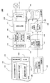
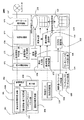
図1は、本発明の第1の実施の形態におけるネットワーク中継システム1000の構成を示す概略ブロック図である。
【0057】
図1を参照して、ネットワーク中継システム1000は、端末100と、記憶媒体110と、中継装置120とを備える。
【0058】
ここで、端末100は、端末100を一意に識別する物理アドレスを保持した端末識別情報保持部101と、中継装置120との間で通信開始及び終了の処理を行う通信開始・終了処理部102と、中継装置120と無線通信を行う無線通信部103と、端末識別情報を情報として含む認識情報を作成する認識情報作成部104と、上記認識情報を表示することができる表示部105とを備える。
【0059】
通信部103が、中継装置(アクセスポイント)120との間で行う通信は、たとえば、IEEE802.11b,IEEE802.11aやIEEE802.11g等に規定されたTCP/IPベースの無線LAN、近距離無線通信であるBluetooth(R)、あるいは携帯電話の電話機と基地局との間の無線通信等を想定している。
【0060】
記憶媒体110は、端末100と予め1対1に対応付けられ、端末100を一意に識別することが可能な物理アドレス情報とユーザ名などの利用者情報を保持している。ここで、「物理アドレス情報」とは、端末100の端末識別情報保持部101に保持された物理アドレス(MACアドレス)と同じ値を表わす情報である。また、記憶媒体110としては、表面にバーコードや2次元コードが印刷された紙製のカード、磁気カード、ICカードなどが考えられる。
【0061】
さらに、図1を参照して、中継装置120は、端末100と無線通信を行う端末通信装置121と、広域網であるインターネットに接続するためのネットワーク通信部122と、識別情報読取装置123と、識別情報登録部124と、識別情報判定部125と、通信開始・終了処理部126と、通信中継部127と、料金入力部128と、度数加算部129と、度数管理部130と、利用者情報保持部(利用者情報データベース)131とを備える。
【0062】
識別情報読取装置123は、端末通信装置121で用いられる端末100の物理アドレスを格納した記憶媒体110から、端末100の物理アドレスや利用者情報を読み取る。識別情報読取装置123としては、例えば、ハンディスキャナー、バーコードリーダー、磁気カードリーダー、ICカードリーダライタ、などを用いることができる。
【0063】
識別情報登録部124は、識別情報読取装置123から読み出した端末100の物理アドレスを利用者端末識別情報として、利用者情報データベース131に登録する。
【0064】
識別情報判定部125は、端末通信装置121により獲得される端末100の物理アドレスと利用者情報データベース131に保持された物理アドレスが一致するか判定する。識別情報判定部125の判定結果が一致している場合は、通信中の端末100の物理アドレスにより、逆に、利用中の「ユーザ名」が特定される。
【0065】
通信開始・終了処理部126は、端末100との間で、通信開始及び終了の処理を行う。
【0066】
通信中継部127は、端末100と公衆回線網、たとえば、インターネット間の中継を行う。すなわち、通信中継部127は、端末通信装置121を介して端末100からインターネットへの中継要求を受けた際に、識別情報判定部125で格納された物理アドレスと一致する物理アドレスを有する端末からの中継要求であると判定された場合にのみ、通信開始・終了処理部126により通信を開始して、インターネットへの中継を行う。
【0067】
なお、「公衆回線網」とは、互いに関係のない複数の組織のコンピュータ等が当該回線を介して相互接続しているものをいう。
【0068】
また、中継装置120の運用者は、料金入力部128により、端末100のユーザが事前に支払った料金を入力する。例えば、識別情報読取装置123で記憶媒体110に保持された物理アドレスに対応して、中継装置120の運用者が、キーボード等から入力する構成とすることができる。
【0069】
度数加算部129は、事前に支払った料金に応じて度数を加算して利用者情報データベース131に登録する。「度数」は利用可能な通信時間または通信量を示すもので、インターネット接続サービスの代金として、事前に支払った利用代金に応じて決められる。
【0070】
度数管理部130は、利用者情報データベース131に格納された度数を取得して、利用時間または利用した通信量に応じて随時度数を減算して、残度数を再び利用者情報データベース131に記録する処理を行う。
【0071】
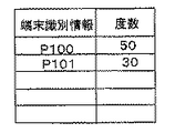
図2は、利用者情報データベース131に格納されている「端末識別情報」である物理アドレスと度数とを示す概念図である。
【0072】
利用者情報データベース131には、記憶媒体110から読み出した利用者の端末100の物理アドレスと、料金入力部128で入力された料金に応じて加算された度数が、関連付けられて保持されている。
【0073】
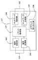
図3は、図1に示した通信中継部127の構成を説明するための概略ブロック図である。
【0074】
図3を参照して、通信中継部127の構成およびその行う処理をさらに詳細に説明する。
【0075】
通信中継部127は、端末100からデータを受信する端末受信部132と、端末100へデータを送信する端末送信部133と、ネットワークからデータを受信するネットワーク受信部134と、ネットワークへデータを送信するネットワーク送信部135と、端末からの要求に対してIPアドレスを割り当てるIPアドレス割り当て部136と、データの送受信の単位であるパケットを構成するパケット構成部137とを備える。
【0076】
ここで、本実施の形態において、端末100の識別情報として用いる物理アドレス(MAC:Media Access Control)は、通常のネットワーク通信時に用いられるデータリンク層のアドレスであり、ネットワークインターフェースカードに固有のものが割り振られている。端末100が固有の物理アドレスを持つネットワークインターフェースカードを装着している場合に、物理アドレスにより端末を一意に特定することができるため、端末の識別情報として、物理アドレスを用いることができる。
【0077】
これに対して、IPアドレス割り当て部136が端末100に対して割り当てるIPアドレスは、物理アドレスの上位レイヤで用いるアドレスであり、中継を含むような通信において、両端の装置を識別することができる。より具体的には、端末100と、端末100がインターネットを介して接続する接続先とを特定することができる。
【0078】
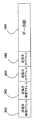
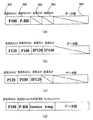
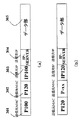
図4は、端末100と中継装置120間で用いられるパケット、および、インターネットから中継装置120に入出力するパケットのフォーマットを表わす概念図である。
【0079】
図4を参照して、パケットは、送信元物理アドレス301、送信先物理アドレス302、送信元IPアドレス303、送信先IPアドレス304及びデータ305を格納する領域で構成されている。
【0080】
図1と図4を参照して、通信中継部127は、識別情報判定部125を用いて、端末から受けたパケットの送信元物理アドレス301によって正規利用者端末であるかを認証し、正規利用者端末であると認証されたときには通信を開始してインターネットへの中継を行う。
【0081】
なお、中継装置120は、例えば、ファストフード店内に設置された無線LAN用アクセスポイントとして使用することが可能である。この場合、例えば、無線LANカードを備えた個人のパソコンを端末100として使用することができる。ファストフード店で買い物をした利用者は、カウンターで店員に個人のパソコンをアクセスポイントに登録してもらう。その後席についた利用者が無線LAN用アクセスポイントに接続してインターネット接続サービス(Webアクセス、電子メール等)を受ける。
【0082】
第1の実施の形態のネットワーク中継システム1000の動作に関して、以下、さらに詳細に説明する。
【0083】
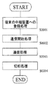
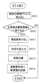
図5は、ネットワーク中継システム1000の処理の手順を表わすフローチャートである。
【0084】
図5を参照して、処理の手順としては、まず、記憶媒体110を用いた端末100の中継装置120への登録処理(ステップS0001)が行われる。続いて、端末100と中継装置120との間の無線通信の開始処理(ステップS0002)が行われ、中継装置120を介した端末100とインターネット通信処理(ステップS0003)と、さらに、端末100と中継装置120との無線通信の切断処理(ステップS0004)とが行われる。以下、各処理手順を詳細に説明する。
【0085】
図5のステップS0001での端末100の中継装置120へ登録処理について、説明する。
【0086】
中継装置120における登録処理としては、中継装置120の識別情報読取装置123で、記憶媒体110から識別情報である物理アドレス(P100)を読み出し、中継装置120の利用者情報データベース131に登録が行われる。
【0087】
次に、図5のステップS0002での端末100と中継装置120との間の無線通信の開始処理について、説明する。
【0088】
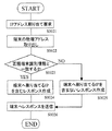
図6は、中継装置120における無線通信の開始処理の手順を示すフローチャートである。また、図7は、各処理手順で使用されるパケットの概念図である。
【0089】
以下、図6および図7を参照して、まず、中継装置120は端末通信装置121を介して、端末100から図7(a)に示すようなIPアドレスの割り当てのリクエストを受ける(ステップS0021)。
【0090】
図7(a)に示すとおり、IPアドレスの割り当てのリクエストパケットには、送信元物理アドレス301に端末100の物理アドレスの値(P100)が、送信先物理アドレス302にブロードキャストを表わす値(P−BB)が、それぞれ設定されている。なお、送信元IPアドレス303、送信先IPアドレス304、データ305には何も設定されていない。
【0091】
中継装置120は、リクエスト送信元物理アドレス301の中から端末100の物理アドレス(P100)を取り出す(ステップS0022)。さらに、中継装置120は、識別情報判定部125を用いて、リクエストの中から取り出した端末100の物理アドレスと識別情報保持部で保持された物理アドレスが一致するか判定する(ステップS0023)。
【0092】
中継装置120は、物理アドレスが予め登録されている正規端末の識別情報と一致する場合は、端末100に対して、通信中継部127を用いて、IPアドレスを情報として含むレスポンスを作成する(ステップS0024)。
【0093】
図7(b)に示すとおり、IPアドレスを情報として含むレスポンスパケットには、送信元物理アドレス301に中継装置120の物理アドレスの値(P120)が、送信先物理アドレス302には端末100の物理アドレスの値(P100)が、送信元IPアドレス303には中継装置のIPアドレスの値(IP120)が、送信先IPアドレス304には端末100に割り当てるIPアドレスの値(IP100)が、それぞれ設定されている。なお、データ305には何も設定されていない。
【0094】
一方、中継装置120は、物理アドレスが一致しない場合は端末に対して、IPアドレスを割り当てないレスポンスを作成する(ステップS0025)。
【0095】
図7(c)に示すとおり、IPアドレスを割り当てないレスポンスパケットには、送信元物理アドレス301に中継装置120の物理アドレスの値(P120)が、送信先物理アドレス302には端末100の物理アドレスの値(P100)が、送信元IPアドレス303には中継装置のIPアドレスの値(IP120)が、それぞれ設定されているが、送信先IPアドレス304およびデータ305には何も設定されていない。そして、中継装置120は、作成したレスポンスを端末通信装置121を介して端末100へ送信する(ステップS0026)。
【0096】
次に、図5のステップS0003での中継装置120を介した端末100とインターネットとの通信処理について、説明する。
【0097】
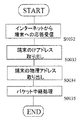
図8は、中継装置120を介した端末100とインターネット通信処理のうち、中継装置120における端末100からインターネットへのパケット中継の手順を示すフローチャートである。また、図9は、各処理手順で使用されるパケットの概念図である。
【0098】
図8および図9を参照して、中継装置120は、端末通信装置121を介して、端末100からインターネットへの接続要求を受ける(ステップS0027)。
【0099】
図9(a)に示すように、インターネットへの接続要求パケットには、送信元物理アドレス301に端末100の物理アドレスの値(P100)が、送信先物理アドレス302に中継装置120の物理アドレスの値(P−120)が、送信元IPアドレス303には端末100に割り当てられたIPアドレスの値(IP100)が、送信先IPアドレス304にはサービスを提供するインターネット上のサーバのIPアドレス(IP−Server)が、それぞれ設定されている。
【0100】
次に、中継装置120は、インターネットへの接続要求パケットの送信元物理アドレス301の中から端末100の物理アドレス(P100)を取り出す(ステップS0028)。さらに、中継装置120は、識別情報判定部125を用いて、リクエストの中から取り出した端末の物理アドレスと利用者情報データベース131中に登録された端末識別情報(物理アドレス)とが一致するか判定する(ステップS0029)。物理アドレスが一致する場合は、中継装置120はインターネットへのパケット中継を行う(ステップS0030)。すなわち、図9(a)のインターネットへの接続要求パケットのうち、送信元物理アドレス301に中継装置120の物理アドレスの値(P−120)を、送信先物理アドレス302に中継装置120が直接通信を行う機器(ルータなど)の物理アドレスの値(P−xx)を、それぞれ図9(b)に示すように設定し直し、ネットワーク通信装置122を介してパケットをインターネット側へ送信する。なお、物理アドレスが一致しなかった場合には、当該パケットは破棄される(ステップS0031)。
【0101】
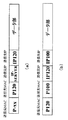
図10は、中継装置120を介した端末100とインターネット通信処理のうち、中継装置120におけるインターネットから端末100へのパケット中継の手順を示すフローチャートである。また、図11は、各処理手順で使用されるパケットの概念図である。
【0102】
図10および図11を参照して、中継装置120は、ネットワーク通信装置122を介して、インターネットから端末100への応答を受ける(ステップS0032)。
【0103】
図11(a)に示すとおり、インターネットからの応答パケットには、送信元物理アドレス301に中継装置120が直接通信を行う機器(ルータなど)の物理アドレスの値(P−xx)が、送信先物理アドレス302に中継装置120の物理アドレスの値(P120)が、送信元IPアドレス303にはサービスを提供するインターネット上のサーバのIPアドレス(IP−Server)が、送信先IPアドレス304には端末100に割り当てられたIPアドレスの値(IP100)が、それぞれ設定されている。
【0104】
次に、中継装置120は、インターネットからの応答パケットの送信先IPアドレス304の中から端末100に割り当てられたIPアドレスの値を取り出し(ステップS0033)、識別情報保持部から当該IPアドレスに対応する端末100の物理アドレスを取り出す(ステップS0034)。
【0105】
次に、中継装置120は、端末100へのパケット中継を行う(ステップS0035)。すなわち、図11(a)のインターネットからの応答パケットのうち、送信元物理アドレス301に中継装置120の物理アドレスの値(P−120)を、送信先物理アドレス302に端末100の物理アドレスの値(P100)を、それぞれ図11(b)に示すように設定し直し、端末通信装置121を介してパケットを端末100へ送信する。
【0106】
次に、図5のステップS0004での端末100と中継装置120との間の無線通信の切断処理について説明する。
【0107】
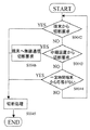
図12は、中継装置120における無線通信の切断処理を示すフローチャートである。
【0108】
図12を参照して、端末100が出した無線通信の切断要求を端末通信装置121で受けたとき(ステップS0042)、または中継装置120側で端末100との無線通信を切断しようとしたとき(ステップS0043)、または一定時間端末100から応答がないとき(ステップS0044)、中継装置120の通信開始・終了処理部126において端末100との無線通信の終了処理を行う(ステップS0045)。
【0109】
ただし、ステップS0043で中継装置120側で端末100との無線通信を切断しようとした場合には、ステップS0045で端末100との無線通信の終了処理を行う前に、端末通信装置121から端末100に対して無線通信の切断要求を送る必要がある(ステップS0046)。
【0110】
ここで、中継装置120側で端末100との無線通信を切断しようとした場合とは、例えば営業時間終了時にインターネット接続サービスを終了するような場合や、後述する度数管理において当該端末100に割り当てられた度数が0になったような場合である。
【0111】
また、ステップS0044において、一定時間端末100から応答がない場合とは、例えば一定間隔で端末100との通信到達確認を行うようなコマンド(Unix(R)のpingコマンドに相当)を発信してその応答がなくなったような場合である。
【0112】
通信開始・終了処理部126における無線通信の終了処理 (ステップS0045)では、登録されていた物理アドレスが識別情報保持部124から抹消され、IPアドレスとの対応情報も破棄される。終了処理以降に端末100からインターネットへの接続要求を受けても、インターネットへの中継は行なわれない。また、対応付けが解消されたIPアドレスを、別の端末に新たに割り当てることも可能となる。
【0113】
なお、第1の実施の形態における端末100において行われる処理は、物理アドレスで利用制限のかけられた無線LANアクセスポイントに対して、無線LANを備えたパソコンが接続してインターネットアクセスを行う処理と同一であるため、ここでは説明は省略する。
【0114】
このようにして、端末の識別情報として物理アドレスを用いることで、端末においては煩雑な設定を行うことなく、新たな装置を追加することなく、インターネットに接続できる。中継装置においては、端末の物理アドレスにより容易に端末を特定することができる。
【0115】
また、中継装置への端末の登録方法として、端末の物理アドレスが保持された記憶媒体を用いることで、煩雑な作業を行うことなく、容易に登録することができる。記憶媒体は様々な場所に携帯することもできるため、中継装置への登録作業が容易となる。
【0116】
[第2の実施の形態]
次に、本発明の第2の実施の形態に係るネットワーク中継システム2000の構成に関して詳細に説明する。
【0117】
ネットワーク中継システム2000の構成は、第1の実施の形態のネットワーク中継システム1000の構成と基本的な部分は同様である。ただし、ネットワーク中継システム2000では、中継装置120へ端末100を登録するための利用者認証情報として、利用者情報(ユーザ名、他)と利用者パスワードを利用者毎に設定し、中継装置120では利用者認証情報を用いて利用者を認証した上で端末100へのインターネット接続サービスの提供可否を判定するための構成が設けられる。
【0118】
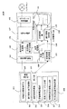
図13は、第2の実施の形態のネットワーク中継システム2000に使用される中継装置120´の概略ブロック図である。
【0119】
図13を参照して、中継装置120´は、第1の実施の形態のネットワーク中継システム1000中の中継装置120の構成に加え、端末100の物理アドレスと関連付けて、利用者パスワードとワンタイムパスワードとを記録する利用者認証情報記憶部132と、利用者情報と利用者パスワードから端末100の利用者を認証する利用者認証部133と、端末100の利用者にワンタイムパスワードを発行するワンタイムパスワード発行部134と、発行されたワンタイムパスワードを出力するワンタイムパスワード出力装置135と、利用者パスワードを入力する利用者パスワード入力装置136とが備わっている。
【0120】
ここで、「利用者パスワード」とは、各利用者を個別に認証できる情報であればよく、たとえば、各利用者がネットワーク中継システム2000を使用するために、事前に登録申請を行う際に、当該利用者に対してネットワーク中継システム2000の運用者が割り当てた数値、文字、記号等の組み合わせからなるパスワードでも良いし、あるいは、ネットワーク中継システム2000の運用者が当該利用者の指紋等のバイオメトリクス情報を予め登録しておいても良い。したがって、「利用者パスワード」は、複数の場所に設置されるネットワーク中継システム2000のそれぞれに対して利用者が共通に使用可能な認証情報である。
【0121】
これに対して、「ワンタイムパスワード」とは、ある特定の場所に設置されたネットワーク中継システム2000を利用するに際して、ワンタイムパスワード出力装置135からその都度発行され、所定の通信の期間、利用者を認証するための情報である。ここで、「所定の通信の期間」は、一度、中継装置120を介して通信を開始した後、その通信を終了するまでの期間としてもよいし、当該利用者に対して登録された度数に対応する期間としてもよい。
【0122】
利用者認証部133とワンタイムパスワード発行部134とは、便宜上中継装置120´の内部に置かれているが、中継装置120´の外部サービスである認証サーバとして実現されてもよい。
【0123】
ワンタイムパスワード出力装置135は、ワンタイムパスワード発行部134で発行されたワンタイムパスワードを出力する。具体的には、ワンタイムパスワード出力装置135は、ディスプレイなどの表示装置、プリンタなどの印刷装置に相当する。利用者パスワード入力装置136は、端末100の利用者が中継装置120´に利用者パスワードを直接入力する部位であり、具体的にはテンキーやキーボード、あるいは指紋等のバイオメトリクス情報入力装置などで構成される。
【0124】
また、端末100には、ワンタイムパスワード出力装置135から出力されたワンタイムパスワードを端末100に入力するためのワンタイムパスワード入力部106が備えられる。
【0125】
すなわち、第2の実施の形態において利用者の認証のために用いる情報としては、以下の4つがある。
【0126】
(1)記憶媒体110に含まれる利用者情報1(ユーザ名等)。
(2)中継装置120の利用者パスワード入力装置136から入力される利用者パスワード。
【0127】
(3)無線通信の接続時に端末100から送られてくる利用者情報2(ユーザ名等)。
【0128】
(4)ワンタイムパスワード発行部134が発行し、無線通信の接続時に端末100から送られてくるワンタイムパスワード。
【0129】
第2の実施の形態のネットワーク中継システム2000では、上記の4つすべてを備えた利用者認証の方法を説明する。なお、実装上は上記の4つの利用者認証方法のうち少なくとも1つを備えていればよい。
【0130】
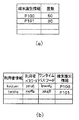
ここで、図14は、利用者情報データベース131に格納されている「端末識別情報」である物理アドレスと度数、ならびに利用者認証情報記憶部132に格納される「利用者認証情報」とを示す概念図である。
【0131】
図14(a)に示す「端末識別情報」は、第1の実施の形態と同様である。
一方、図14(b)に示すように、利用者ごとに設定される利用者情報(ユーザ名等)と利用者パスワードは、あらかじめ利用者認証情報記憶部132に登録されているものとする。利用者に対しては、設定した利用者情報(ユーザ名等)と利用者パスワードがあらかじめ通知されており、記憶媒体110には、端末100の物理アドレスに加えて利用者情報(ユーザ名等)が含まれているとする。利用者情報としては、ユーザ名の他、例えばクレジットカード番号のような決済情報のようなものを含んでいてもよい。
【0132】
さらに、利用者認証情報記憶部132には、利用者情報と関連付けて、ワンタイムパスワード発行部134で発行されたワンタイムパスワードと、端末識別情報(物理アドレス)も格納されるものとする。
【0133】
以下、ネットワーク中継システム2000の処理の手順について説明する。
ネットワーク中継システム2000の処理の基本的な流れは、図5に示した実施の形態1のネットワーク中継システム1000の処理と同様である。
【0134】
ただし、ネットワーク中継システム2000では、図5のステップS0001〜S0004の個々の処理の具体的な内容が、ネットワーク中継システム1000とは異なる。
【0135】
したがって、まず、ネットワーク中継システム2000でも、図5のステップS0001と同様に、記憶媒体110を用いて端末100の中継装置120への登録処理が行われる。
【0136】
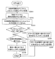
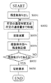
図15は、第1の実施の形態での処理に加えて行なわれる中継装置120´の第2の実施の形態特有の処理を説明するためのフローチャートである。
【0137】
図15を参照して、中継装置120´の識別情報読取装置123で、記憶媒体110から利用者情報(ユーザ名等)と端末の識別情報(物理アドレス)を読み出す(ステップS0151)。
【0138】
次に利用者パスワード入力装置136を介して端末100の利用者が入力した利用者パスワードを取得する(ステップS0152)。中継装置120´は、ステップS0151で取得された利用者情報(ユーザ名等)とステップS0152で取得した利用者パスワードとを組み合わせて利用者認証部133に送り、利用者認証部133は、登録された正規の利用者であるかを調べる(ステップS0153)。
【0139】
利用者認証部133で正規の利用者でないと判断された場合には、表示装置等にエラーメッセージを出力して(ステップS0154)、処理を終了する。
【0140】
一方、利用者認証部133で正規の利用者であると判断された場合には、ワンタイムパスワード発行部134がワンタイムパスワードを発行する(ステップS0155)。
【0141】
記憶媒体110から読み出した物理アドレス、利用者パスワード入力装置136から入力された利用者パスワード、ワンタイムパスワード発行部134が発行したワンタイムパスワードは、組み合わされて利用者認証情報記憶部132に保持される(ステップS0156)。
【0142】
なお、このステップにおいて、利用者パスワードが利用者認証部133での認証に使用済である場合には、利用者パスワードを保持する必要はない。そして、発行されたワンタイムパスワードはワンタイムパスワード発行部134から出力され、端末100の利用者に渡される(ステップS0157)。
【0143】
なお、利用者に渡されたワンタイムパスワードは、利用者が端末100のワンタイムパスワード入力部106から端末100に与え、たとえば、端末識別情報保持部101に端末識別情報とともに格納される構成とすることが可能である。
【0144】
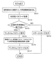
図16は、図5のステップS0002において、端末100と中継装置120´との間の無線通信の開始処理として、第1の実施の形態での処理に加えて行なわれる中継装置120´の第2の実施の形態特有の処理を説明するためのフローチャートである。
【0145】
図16を参照して、中継装置120´は、端末100から端末通信装置121を介して、図7(d)で表されたような利用者情報(ユーザ名等)およびワンタイムパスワードを含むパケットを受信し(ステップS2001)、受信したパケットの送信元物理アドレスを端末100の物理アドレスとして取り出す(ステップS2002)。
【0146】
次に、ステップS2002で取り出された物理アドレスに関連づけられて保持されているワンタイムパスワードと利用者パスワードとを利用者認証情報記憶部132から取り出す(ステップS2003)。
【0147】
ステップS2001で受信したワンタイムパスワードとステップS2003で取り出されたワンタイムパスワードとを比較し(ステップS2004)、一致していなければ端末100にエラーを返すあるいはIPアドレスを割り当てないレスポンスを返して(ステップS2005)処理を終了する。
【0148】
一方、ステップS2004で一致していれば、ステップS2001で受信された利用者情報(ユーザ名等)とステップS2003で取り出された利用者パスワードとを組み合わせて利用者認証部133に送り、登録された正規の利用者であるかを調べる(ステップS2006)。
【0149】
利用者認証部133で正規の利用者でないと判断された場合には、端末100にエラーを返すあるいはIPアドレスを割り当てないレスポンスを返して(ステップS2007)処理を終了する。
【0150】
利用者認証部133で正規の利用者であると判断された場合には、端末100にIPアドレスを割り当てるレスポンスを返して(ステップS2008)処理を終了する。以降の通信では、端末100は正規の利用者のものであるとみなして、中継装置120はインターネットとの中継サービスを提供する。
【0151】
なお、端末100では無線通信の開始処理で、利用者情報(ユーザ名等)とワンタイムパスワードとを設定し、それらを含むパケットを生成、送信する。
【0152】
このようにして、利用者認証情報を用いることで、中継装置への端末登録の際には、不正に端末が登録されることを防ぐことができ、中継装置への接続要求時には、利用者認証を行った上で端末に対してIPアドレスを割り当てるため、他の利用者が不正に利用することを防ぐことができる。
【0153】
[第3の実施の形態]
次に、本発明の第3の実施の形態のネットワーク中継システムに関して詳細に説明する。
【0154】
第3の実施の形態のネットワーク中継システムの構成は、第1の実施の形態のネットワーク中継システム1000と同様である。ただし、第3の実施の形態では、第1の実施の形態のネットワーク中継システム1000の行う処理に加えて、インターネットへの通信時間または通信量に応じて課金が行われる。課金は、支払った利用代金に応じて決められた度数により行われ、使用した通信時間あるいは通信量に応じて度数が減算されて0になると、端末100は中継装置120と通信できなくなる。
【0155】
処理の手順は、支払った利用料金に応じた度数の登録処理と、使用した通信時間あるいは通信量に応じた度数減算処理に分けられる。
【0156】
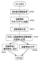
図17は、中継装置120へ度数を登録する処理の手順を表すフローチャートである。ここで、図5の端末100の登録処理(ステップS0001)において、端末100の登録処理と同時に、度数の登録が行われるものとする。
【0157】
図17を参照して、中継装置120の識別情報読取装置123で、記憶媒体110から識別情報である物理アドレス(P100)を読み出す(ステップS0011)。
【0158】
識別情報判定部125を用いて、保持された物理アドレスと一致するか判定する(ステップS0012)。一致すると判定された場合には、利用者情報保持部131により物理アドレスと関連付けて保持されている度数を取り出す(ステップS0013)。
【0159】
料金入力部128により支払った料金を入力する(ステップS0014)。なお、一致すると判定されなかった場合には度数の登録処理を終了する。度数加算部130により支払った料金に応じて度数を加算する(ステップS0015)。利用者情報保持部により物理アドレスと関連付けて度数を保持する(ステップS0016)。
【0160】
なお、この度数は、第2の実施の形態で説明した利用者名、利用者パスワードと関連付けて度数を保持するようにしてもよい。これにより、通信時には端末ごとではなく、利用者ごとに課金することが可能になる。
【0161】
また、中継装置120への料金の入力は、ファーストフード店などで利用者が支払った金額に応じて、店員がレジスタのキーボード等から料金を入力する。
【0162】
図18は、中継装置120における使用した通信時間あるいは通信量に応じた度数減算処理の手順を表すフローチャートである。
【0163】
すなわち、図18に示した処理は、図5のステップS0002において行われる処理である。
【0164】
図18を参照して、中継装置120は、通信開始処理が行われると、利用者情報保持部131により物理アドレスと対応付けて保持されていた度数を読み出す(ステップS0051)。
【0165】
続いて、度数管理部131により、ある一定の通信時間あるいは通信量となるまで待ち(ステップS0052)、度数を減算する(ステップS0053)。残度数を前記度数保持部127に記録する(ステップS0054)。
【0166】
度数が0になった場合は、度数減算処理を終了し(ステップS0055)、中継装置120に対して切断処理を要求する(ステップS0056)。度数減算処理の終了は、図5の切断処理(ステップS0004)が行われる前に行われる。
【0167】
なお、ポイントカードとして、残度数は記憶媒体で管理されるようにしてもよい。これは、端末100の中継装置120への登録時に、残度数を記憶媒体から読み出して、支払った利用料金に応じて度数を加算し、記憶媒体に書き出す。中継装置120でも、残度数を管理する。通信の終了処理後に、中継装置120が管理していた残度数を記憶媒体に書き出すことにより、ポイントカードとして度数を管理する。また、記憶媒体としては、磁気カード、ICカードなどで、中継装置120が読み取ることが出来るものであればよい。
【0168】
このようにして、インターネットへの通信時間または通信量に応じて、度数を減算して接続を管理することで、課金ができるようになる。
【0169】
[第4の実施の形態]
第4の実施の形態は、第1〜第3の実施の形態の変形であり、中継装置120または中継装置120´からのメッセージを端末100に伝達する機能を有する。例えば、以下のようなメッセージが想定できる。
【0170】
(1)端末100の物理アドレスを中継装置120(または中継装置120´)に登録しない状態で、端末100が中継装置120(または中継装置120´)からインターネット接続サービスを受けようとした場合に、先に登録処理を行うよう促すメッセージを伝達する。
【0171】
(2)端末100の利用者の認証情報(利用者情報と利用者パスワード)が中継装置120(または中継装置120´)あるいは外部の認証サーバの利用者認証部133あらかじめ登録されていない状態で、端末100が中継装置120(または中継装置120´)からインターネット接続サービスを受けようとした場合に、先に利用者登録処理を行うよう促すメッセージを伝達する。
【0172】
(3)中継装置120(または中継装置120´)の度数管理部130により度数を監視して、度数を保持する利用者情報保持部131で保持された残度数を監視し、残度数がある一定の度数よりも少なくなった時に、残度数が少ないことを端末100に対して通知するメッセージを伝達する。
【0173】
以上のようなメッセージを通知する構成としては、中継装置120(または中継装置120´)中に、上記(1)〜(3)のメッセージを発信する必要があるかを判断する制御部を設け、この制御部からの制御にしたがって端末通信装置121から端末100に対してメッセージが送信されるものとすればよい。また、端末100側では、端末100の表示部105の画面に残度数を表示する、端末100側で警告音を鳴らす、端末100にメールで知らせる方法などがあり、これらは1つまたは複数を組み合わせることができる。
【0174】
具体的には、例えば、端末100が携帯電話通信可能であり携帯電話メールを受信できるとする。無線通信処理の開始時に端末通信装置121を介して端末100の携帯電話メールアドレスを含むパケットを受信していれば、携帯電話メールを利用して端末100にメッセージを送付することができる。
【0175】
また、図6で説明した中継装置120における無線通信の開始処理の手順では、物理アドレスが登録されていない場合にはIPアドレスを割り当てないとしているが、とりあえずIPアドレスを割り当てて、中継処理時に送信元物理アドレスまたは送信元IPアドレスを見てインターネットへの中継を行わない、あるいは中継装置120の内部コンテンツにのみアクセス可能とするという実装も可能である。この場合、端末100のブラウザがWebアクセスを行おうとしてインターネットへのパケットを送ってきた場合、インターネットへ中継を行わずに中継装置120からのメッセージが書かれたページへリダイレクトするような処理も考えられる。
【0176】
また、IPアドレスの割り当てが終わった後ならば、無線通信処理の開始時に端末通信装置121を介して端末100のメールアドレスを含むパケットを受信していれば、無線通信を介して直接メッセージをメールとして届けることもできる。
【0177】
上述した(3)のようなメッセージを送信する場合には、中継装置120(または中継装置120´)が端末100に対して残度数が少ないことまたは残度数が0に近づいたことを通知することで、利用者は注意を促され、残度数の加算などを行うことができる。
【0178】
[第5の実施の形態]
次に、本発明の第5の実施の形態のネットワーク中継システムの構成および動作に関して詳細に説明する。
【0179】
図19は、第5の実施の形態のネットワーク中継システム3000の構成を説明するための概略ブロック図である。
【0180】
ネットワーク中継システム3000は、端末210と中継装置120で構成されている。しかしながら、ネットワーク中継システム1000の構成とは異なり、記憶媒体110を含まない。その他、第1の実施の形態のネットワーク中継システム1000と同一または相当部分には、同一の符号を付している。
【0181】
ネットワーク中継システム3000の中継装置120の構成は、第1の実施の形態のネットワーク中継システム1000と同様である。
【0182】
しかしながら、端末210は、表示部213の表示画面上に端末210の物理アドレスを情報として含む認識情報を作成する。
【0183】
中継装置120は、図5のステップS0001に相当する処理において、端末210の画面に表示された認識情報をスキャナやカメラで読み取り、認識情報を解析して物理アドレスを取り出すことにより、端末210の中継装置120へ登録処理を行う。
【0184】
以下、図19を参照して、端末210の構成を説明する。端末210は、端末を一意に識別する物理アドレスを保持した端末識別情報保持部211と、端末の物理アドレスを情報として含む認識情報を作成する認識情報作成部212と、認識情報を保持する認識情報記憶部219と、認識情報を表示する表示部213と、中継装置120と通信開始及び終了処理を行う通信開始・終了処理部214と、中継装置120と無線通信を行う通信部215と、認識情報を表示する際に必要となる表示パスワードを入力する表示パスワード入力部216と、及び当該端末の利用者を認証するための利用者認証情報を入力する利用者認証情報入力部217と、該利用者認証情報入力部で入力された利用者認証情報を保持する利用者認証情報保持部218とを備えている。
【0185】
以下、さらに、端末210の物理アドレスを含む認識情報を作成し表示する方法について、実施の手順を説明する。
【0186】
図20は、端末210において、物理アドレスを情報として含む認識情報を生成して表示または印字する手順を説明するためのフローチャートである。
【0187】
図20を参照して、端末210は、端末識別情報を取得する(ステップS0061)。端末識別情報とは、端末210そのものに割り当てられた物理アドレス、または、無線LANカードのように端末210に装着して使用する通信装置の物理アドレスである。
【0188】
次に、端末210は、認識情報を作成するプログラムを起動させ(ステップS0062)、認識情報作成プログラムにより端末210の物理アドレスを情報として含む認識情報を作成する(ステップS0063)。なお、認識情報作成の過程で、例えばユーザ名などの利用者認証情報も含ませてもよい。
【0189】
次に、端末210は、作成した認識情報を認識情報記憶部219に記憶させ (ステップS0064)、利用者の指示に従って認識情報を端末210の表示画面に表示させる(ステップS0065)、または紙などの媒体に認識情報を印刷する(ステップS0066)。なお、ステップS0065におけるユーザの指示として、表示パスワード入力部216から表示パスワードが入力された場合のみ表示を行うとしてもよい。端末100の物理アドレスを含む認識情報は、端末100の表示画面に常時表示されないため、盗み見などが防止でき安全性が向上する。
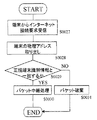
【0190】
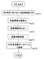
図21は、中継装置120側で登録する手順を示すフローチャートである。図21では、中継装置120が物理アドレスを情報として含む認識情報を端末210の表示画面から読み取り、認識情報を解読して物理アドレスを取得し、登録する手順を示す。
【0191】
図21を参照して、認識情報の表示された端末210の画面を中継装置の識別情報読取装置123にかざすことで、中継装置120は、端末210に表示された認識情報を読み取る(ステップS0071)。
【0192】
次に、中継装置120は、読み取った情報の中から認識情報の位置を検出する(ステップS0072)。その中で、中継装置120は、認識情報の部分のみを切り出し(ステップS0073)、切り出した認識情報を解読する(ステップS0074)。
【0193】
さらに、中継装置120は、端末識別情報(端末210の物理アドレス)を取得して、中継装置120の識別情報登録部124で利用者情報データベースに登録する(ステップS0075)。
【0194】
端末210で利用者認証部から取得した利用者認証情報を含めた認証情報を作成し、中継装置120で端末に表示された認証情報を読み取り、利用者認証をして端末210を登録する手順については、実施の形態1と同様であるので、その説明は繰返さない。
【0195】
なお、第5の実施の形態における「認識情報」とは、例えば、2次元コードやバーコードなどで表されたものであり、中継装置120の識別情報読取装置123とは、例えば2次元コードやバーコードを読み取ることができるスキャナなどである。
【0196】
さらに、「2次元コード」とは、記録面に2次元的に白黒の情報を並べてデジタル情報を記録する方式であり、QRコード、MaxiCode、PDF417(2次元バーコード)などが知られている。デジタルデータのビットに対応する情報は、あるいは白黒の桝目に、あるいは白黒のバーの幅に、マッピングされて記録される。バーコードが数十バイト程度の情報量しかもたないのに対し、2次元コードは1Kバイト程度の情報を記録することが可能である。
【0197】
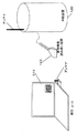
図22は、端末210の表示画面に端末210の物理アドレスを情報として含む2次元コードが表示され、中継装置120の識別情報読取装置123で認識情報を読み取る手順を説明する概念図である。
【0198】
例えば、ファーストフード店内に設置された無線LAN用アクセスポイントが設置されている場合、買い物をした利用者は2次元コードが表示された個人のパーソナルコンピュータ(端末210)をカウンターで提示する。店員はレジに設置されたスキャナ(識別情報読取装置123)でパソコンの画面に表示された2次元コードを読み取る。2次元コードからデコードされた物理アドレスは、アクセスポイントを管理するサーバに送られ、識別情報保持部124に登録される。
【0199】
このようにして、端末210の物理アドレスを情報として含む認識情報を端末側で作成し、端末の表示画面に表示させた認識情報を中継装置120が読み取ることで、端末の物理アドレスが容易に公開されないという点で、安全性が向上する。
【0200】
[第6の実施の形態]
第6の実施の形態のネットワーク中継システムは、第4の実施の形態の変形であり、端末100の代わりに、第5の実施の形態の端末210を用いる構成である。
【0201】
すなわち、端末100の物理アドレスを中継装置120に登録しない状態で、端末100が中継装置120からインターネット接続サービスを受けようとした場合に、先に登録処理を行うよう促すメッセージが、中継装置120から端末装置210に伝達される。さらに、中継装置120は、このようなメッセージばかりでなく、端末210に物理アドレスを含む認識情報を生成するためのプログラムを配布する。
【0202】
例えば、図6の中継装置120における無線通信の開始処理の手順において、ステップS0025の処理を行う代わりに、登録されていない端末210に対してもとりあえずIPアドレスを割り当てる。その上で、登録されていない端末210に対しては、中継処理時に送信元物理アドレスまたは送信元IPアドレスを見てインターネットへの中継を行わない、あるいは中継装置120の内部コンテンツにのみアクセス可能とするという実装を行う。
【0203】
この場合、登録されていない端末210のブラウザがWebアクセスを行おうとしてインターネットへのパケットを送ってきた場合、インターネットへ中継を行わずに中継装置120からのメッセージが書かれたページへリダイレクトするような処理も考えられる。
【0204】
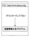
図23は、このように、中継装置120からのメッセージが書かれたページへリダイレクトするような処理を行う場合に、端末210に表示される画面を示す概念図である。
【0205】
図23に示すとおり、このページから物理アドレスを含む認識情報を生成するためのプログラムがダウンロードできるようにしておく。
【0206】
また、第4の実施の形態で携帯電話メールや無線通信を介したメールによりメッセージを伝達する方法について述べたが、これらのメールの添付データとして物理アドレスを含む認識情報を生成するためのプログラムをつけて、端末210に送信することも可能である。これにより、端末210はあらかじめ物理アドレスを含む認識情報を生成するためのプログラムをもっていなくとも、その場でプログラムをダウンロードすることができ、物理アドレスその他を含む認識情報(2次元コード)を生成表示することができる。
【0207】
なお、以上説明した、実施の形態1〜6において、上記の端末100(または端末210)および中継装置120(または中継装置120´)の行う処理は、プログラムによるソフトウェアとして実現される。
【0208】
このプログラムはコンピュータで読み取り可能な記憶媒体に格納して配布することができ、各処理は上記プログラムが、上記の端末100(または端末210)および中継装置120(または中継装置120´)にインストールされることで実行される構成とすることが可能である。
【0209】
記憶媒体の例としては、磁気テープやカセットテープなどのテープ系の媒体、フロッピー(R)ディスクやハードディスク等の磁気ディスクやCD−ROM(Compact Disc Read Only Memory)/MO(Magneto−Optics)ディスク/MD(MiniDisc)/DVD(Digital Versatile Disc)などの光ディスクなどからなるディスク系の媒体、ICカードや光カード等のカード系、マスクROM(Read Only Memory)、EPROM(Erasable and Programmable Read Only Memory)、EEPROM(Electrically Erasable and Programmable Read Only Memory)、フラッシュROM等による半導体メモリを含めた固体記憶素子にプログラムを担持する媒体などいずれであってもよい。
【0210】
今回開示された実施の形態はすべての点で例示であって、制限的なものではないと考えるべきである。本発明の範囲は、上記した説明ではなく特許請求の範囲によって示され、特許請求の範囲と均等の意味及び範囲内ですべての変更が含まれることが意図される。
【0211】
【発明の効果】
以上のように、本発明によれば、インターネット接続サービスを提供する中継装置に対して、簡単に利用者の端末を登録することができ、端末に特別な装置を導入しなくても、不特定多数の人がインターネットを容易に利用できるようになる。利用者は、端末に対して複雑な設定を行うことなく、インターネットに接続でき、中継装置においては端末を容易に特定して課金を行うことができる。
【0212】
さらに、中継装置に対する端末の登録の際には、利用者認証情報を用いて利用者を認証することで、正規利用者が所有すると認証された端末のみが登録され、不正に端末が登録されることを防ぐことができる。
【図面の簡単な説明】
【図1】本発明の第1の実施の形態におけるネットワーク中継システム1000の構成を示す概略ブロック図である。
【図2】利用者情報データベース131に格納されている「端末識別情報」である物理アドレスと度数とを示す概念図である。
【図3】図1に示した通信中継部127の構成を説明するための概略ブロック図である。
【図4】端末100と中継装置120間で用いられるパケット、および、インターネットから中継装置120に入出力するパケットのフォーマットを表わす概念図である。
【図5】ネットワーク中継システム1000の処理の手順を表わすフローチャートである。
【図6】中継装置120における無線通信の開始処理の手順を示すフローチャートである。
【図7】各処理手順で使用されるパケットの概念図である。
【図8】中継装置120における端末100からインターネットへのパケット中継の手順を示すフローチャートである。
【図9】各処理手順で使用されるパケットの概念図である。
【図10】中継装置120におけるインターネットから端末100へのパケット中継の手順を示すフローチャートである。
【図11】各処理手順で使用されるパケットの概念図である。
【図12】中継装置120における無線通信の切断処理を示すフローチャートである。
【図13】第2の実施の形態のネットワーク中継システム2000に使用される中継装置120´の概略ブロック図である。
【図14】利用者情報データベース131に格納されている「端末識別情報」である物理アドレスと度数、ならびに利用者認証情報記憶部132に格納される「利用者認証情報」とを示す概念図である。
【図15】中継装置120´の第2の実施の形態特有の処理を説明するためのフローチャートである。
【図16】端末100と中継装置120´との間の無線通信の開始処理として、中継装置120´の第2の実施の形態特有の処理を説明するためのフローチャートである。
【図17】中継装置120へ度数を登録する処理の手順を表すフローチャートである。
【図18】中継装置120における使用した通信時間あるいは通信量に応じた度数減算処理の手順を表すフローチャートである。
【図19】第5の実施の形態のネットワーク中継システム3000の構成を説明するための概略ブロック図である。
【図20】端末210において、物理アドレスを情報として含む認識情報を生成して表示または印字する手順を説明するためのフローチャートである。
【図21】中継装置120側で登録する手順を示すフローチャートである。
【図22】中継装置120の識別情報読取装置123で認識情報を読み取る手順を説明する概念図である。
【図23】中継装置120からのメッセージが書かれたページへリダイレクトするような処理を行う場合に、端末210に表示される画面を示す概念図である。
【符号の説明】
100 端末、101 端末識別情報保持部、102 通信開始・終了処理部、103 無線通信部、104 認識情報作成部、105 表示部、110 記憶媒体、120,120´ 中継装置、121 端末通信装置、122 ネットワーク通信部、123 識別情報読取装置、124 識別情報登録部、125 識別情報判定部、126 通信開始・終了処理部、127 通信中継部、128料金入力部、129 度数加算部、130 度数管理部、131 利用者情報保持部、134 ワンタイムパスワード発行部、135 ワンタイムパスワード出力装置、136 利用者パスワード入力装置、210 端末、211 端末識別情報保持部、212 認識情報作成部、213 表示部、214 通信開始・終了処理部、215 通信部、216 表示パスワード入力部、217 利用者認証情報入力部、218 利用者認証情報保持部、219 認識情報記憶部、1000,2000,3000 ネットワーク中継システム。[0001]
TECHNICAL FIELD OF THE INVENTION
The present invention relates to a terminal that can receive a connection service to the Internet via a relay device connected by wireless communication, and a network relay system including the terminal and the relay device.
[0002]
[Prior art]
2. Description of the Related Art In recent years, Internet connection services for terminals have been provided via relay devices that relay connection to the Internet installed in streets, shops, and the like.
[0003]
2. Description of the Related Art Conventionally, as a method of receiving an Internet connection service, there is a method of connecting a user terminal to an access point provided by an Internet connection provider by dial-up. In this case, the user has to contract in advance with the Internet connection service provider and perform complicated settings such as an access point telephone number, a user ID and a password issued by the service provider on the terminal.
[0004]
However, in order to receive a connection service from the user's terminal to the Internet via a relay device installed in a public place such as a street or a store, the setting is easy at the user's terminal, and the relay device is also required. It is desired that a terminal can be easily specified and billing can be performed. Further, a mechanism for easily registering a user terminal with a relay device is desired.
[0005]
As a first prior art, Japanese Patent Application Laid-Open No. 2001-111725 discloses that a complicated setting is not performed on a user terminal, and that a user terminal can be easily specified and charged in a relay device. A billing system "is disclosed.
[0006]
In the "billing system" disclosed in Japanese Patent Application Laid-Open No. 2001-111725, a terminal of a user to which a physical address is set is connected to the Internet through a public connection terminal connectable to the terminal of the user. Here, by using a physical address for uniquely identifying the terminal as the terminal identification information, the terminal can be connected to the Internet without performing complicated settings. On the relay device side, the terminal can be easily specified by the physical address used when the terminal is connected to the relay device, and billing can be performed for each user associated with the terminal.
[0007]
As a second prior art, Japanese Patent Application Laid-Open No. Hei 10-222446 discloses that a complicated terminal setting for connecting to the Internet is stored in a storage medium, and the Internet is automatically installed by attaching the storage medium to the terminal. As an art for connecting to the Internet, "Internet access apparatus and system using information storage card and its method" is disclosed.
[0008]
In Japanese Patent Application Laid-Open No. 10-222446, when a user terminal connects to an access point provided by an Internet connection company by dial-up and receives an Internet service, the telephone number of the access point and the user ID are used. By attaching the storage medium storing the password to the terminal, a series of processes from connection of the terminal to the network to acquisition of information on the Internet can be automatically executed. By storing the complicated settings on the terminal side in the storage medium, the user can easily access the Internet without performing complicated settings on the terminal.
[0009]
[Problems to be solved by the invention]
However, according to the technique disclosed in Japanese Patent Application Laid-Open No. H10-222446, the settings of a terminal for connecting to the Internet are stored in a card-type storage medium, and the terminal requires a special device for reading the storage medium. . In such a case, the terminal (notebook computer) cannot be connected to the access point (relay device) without a special device or software for reading the setting contents.
[0010]
On the other hand, in Japanese Patent Application Laid-Open No. 2001-111725, a terminal can be connected to the Internet without setting by using a physical address as identification information of the terminal, and the terminal can be connected to the relay device by using the identification information of the terminal. You can specify and charge. However, there is no description of a method for easily registering identification information of a user terminal in a relay device.
[0011]
Actually, in order to register a user terminal in the relay device, it is necessary to manually input a physical address as identification information for uniquely identifying the terminal. Alternatively, it is necessary to perform a complicated operation such as reading a physical address by directly connecting a cable connected to a network interface card of the terminal to the connector on the relay device side.
[0012]
The present invention has been made in order to solve the above-described problems, and an object of the present invention is to provide a relay device that provides a connection service to a public line network such as the Internet with a simple operation of a user. When registering a terminal and receiving a connection service via the relay device, the relay device, the terminal, and the network relay system are easy to set in the terminal, and can easily specify the terminal even in the relay device and perform charging. It is to provide.
[0013]
[Means for Solving the Problems]
In order to achieve the above object, according to one aspect of the present invention, there is provided a relay device used as an access point when a terminal accesses a public line network, and a terminal communication means for performing wireless communication with the terminal; Network communication means for connecting to a network, identification information reading means for reading identification information including at least identification information uniquely identifying the terminal, identification information reading means for reading terminal identification information from the identification information, and identification information reading means; Identification information holding means for holding the identification information of the read terminal, and when the terminal requests a relay to the public network, the identification information transmitted from the terminal device for establishing communication between the terminal and the relay device is held. When the identification information matches, relaying is performed on the public network, and when a request for relaying from the public network to the terminal is performed, relaying to the terminal is performed using the held identification information. And a signal relay means.
[0014]
According to the present invention, it is possible to realize a network relay process in which a terminal can connect to the Internet via a relay device. In such a relay process, the relay device reads the recognition information displayed by the terminal, and holds the identification information of the terminal. When the terminal requests the relay device to relay to the Internet using wireless communication, the relay device establishes wireless communication only with the terminal holding the identification information and provides the relay to the Internet. For this reason, the process of registering the terminal that provides the relay to the Internet to the relay device is simplified.
Preferably, the recognition information includes, in addition to the identification information, user authentication information for authenticating a user of the terminal, and a user authentication information reading unit that reads the user authentication information from the recognition information; User authentication means for authenticating whether the user authentication information read by the reading means is an authorized user of the relay device, and the identification information holding means is an authorized user by the user authentication means. When it is determined that the terminal has been identified, the identification information of the terminal read by the identification information reading means is held.
[0015]
Thus, registration of the terminal to the relay device is performed by the relay device reading identification information including user authentication information indicating a legitimate user such as a user ID, authenticating the user with the user authentication information, and identifying the terminal. Holds information. For this reason, the process of registering the terminal that provides the relay to the public line network in the relay device is simplified. The relay device can provide the relay to the public network only to the terminal owned by the authorized user.
[0016]
Preferably, the apparatus further comprises a password input unit for inputting a user password, wherein the user authentication unit is a combination of the user authentication information read by the user authentication information reading unit and the password input by the password input unit. Authenticates whether the user is an authorized user of the relay device.
[0017]
As a result, the relay device reads the recognition information including the user authentication information, and furthermore, when the user enters the password, authenticates the user by combining the user authentication information and the password. Increase.
[0018]
Preferably, further comprising a one-time password output means for outputting a one-time password when the user is determined by the user authentication means is a legitimate user, when a relay request from the terminal to the public network, When the one-time password is transmitted from the terminal, the communication relay means performs a relay process.
[0019]
Accordingly, the relay device issues the one-time password and relays the communication only when the one-time password is transmitted from the terminal, so that the accuracy of authenticating the authentic terminal is increased.
[0020]
Preferably, a frequency input means for inputting a frequency with a communication time or a communication amount as a parameter in association with the identification information of the terminal, and a terminal assigned in association with the identification information of the terminal held in the identification information holding means. Frequency holding means for holding frequency, frequency measuring means for measuring communication time or traffic volume when communication is relayed between the terminal and the public line network, information and frequency measuring means input by frequency input means A frequency changing means for changing the frequency held by the frequency holding means on the basis of the information measured in the step (b), wherein the communication relay means is configured to execute the processing when the frequency held by the frequency holding means becomes a predetermined value. Then, the relay to the terminal having the identification information associated with the frequency is stopped.
[0021]
Thereby, for example, the user pays the usage fee of the public network in advance, and registers the frequency with the communication time or the communication amount as a parameter in the relay device according to the paid usage fee. On the other hand, charging based on the communication time or the communication amount can be easily performed.
[0022]
Preferably, when receiving a relay request from the terminal to the public network, if the identification information of the terminal used for communication with the terminal does not match the identification information held in advance, the terminal And means for issuing warning information for urging the relay device to read the recognition information including the identification information.
[0023]
Thus, for example, when the terminal attempts to receive a public network connection service from the relay device without registering the identification information of the terminal in the relay device, the terminal performs the registration process to the relay device first. Can be encouraged.
[0024]
Preferably, when receiving a relay request from the terminal to the public network, if the identification information of the terminal used for communication with the terminal does not match the identification information held in advance, the terminal Means for transmitting a generation program for generating recognition information including identification information.
[0025]
Thereby, for example, when the terminal does not have a program for generating displayable recognition information, the relay device can distribute a program for generating recognition information including terminal identification information to the terminal. .
[0026]
According to another aspect of the present invention, there is provided a terminal, a wireless communication unit for performing wireless communication with another device, and an identification holding identification information for uniquely identifying the terminal used when performing wireless communication with another device. The information processing apparatus includes an information holding unit, a recognition information generating unit that generates recognition information including at least identification information as a two-dimensional code, and a display unit that displays the recognition information as a two-dimensional code.
[0027]
Accordingly, the terminal can display, as a two-dimensional code, recognition information including identification information assigned to the terminal itself or the network interface card of the terminal as information on the display screen. For this reason, another device provided with the two-dimensional code reading means can easily acquire the identification information of the terminal by reading the displayed recognition information. In addition, by using a two-dimensional code, a large amount of information can be used as recognition information. The contents included in the recognition information cannot be understood at a glance of the two-dimensional code. Can be used.
[0028]
Preferably, the apparatus further includes a user authentication unit that inputs or holds user authentication information for authenticating a user of the terminal, and the recognition information includes user authentication information in addition to the identification information.
[0029]
The terminal can display recognition information including user authentication information in addition to the terminal identification information. For this reason, another device equipped with the two-dimensional code reading means can easily acquire the authentication information of the user of the terminal by reading the displayed recognition information.
[0030]
Preferably, a display password input unit is further provided, and when the display password is input, the recognition information is displayed on the display unit.
[0031]
Thus, the recognition information can be displayed on the display screen of the terminal only when the password is input. Since the recognition information is displayed only at the time of inputting the password, the recognition information is not always displayed, and only the authorized person can display the recognition information, so that the security related to the recognition information can be enhanced.
[0032]
According to still another aspect of the present invention, there is provided a terminal control program for controlling an operation of a terminal device having wireless communication means for performing wireless communication with another device, which is used when performing wireless communication with another device. A computer is caused to execute a step of holding identification information for uniquely identifying a terminal, a step of generating recognition information including at least the identification information as a two-dimensional code, and a step of displaying the recognition information as a two-dimensional code.
[0033]
Preferably, the method further includes a step of inputting the display password to the terminal device, and the step of displaying the display password as a two-dimensional code displays recognition information when the display password is input.
[0034]
According to still another aspect of the present invention, there is provided a computer-readable recording medium, a terminal control program for controlling operation of a terminal device having wireless communication means for performing wireless communication with another device, Holding identification information for uniquely identifying a terminal used when performing wireless communication with another device, generating recognition information including at least the identification information as a two-dimensional code, and displaying the recognition information as a two-dimensional code. And a terminal control program for causing a computer to execute the steps.
[0035]
The storage medium can hold the processing as a program, and the same processing as that of the terminal can be performed by reading the processing into a terminal provided with a unit that reads information from the storage medium.
[0036]
Preferably, the terminal control program further includes a step of inputting a display password to the terminal device, and the step of displaying as a two-dimensional code displays recognition information when the display password is input.
[0037]
According to yet another aspect of the present invention, there is provided a network relay system including a relay device used as an access point when accessing a public line network, and a terminal performing wireless communication with the relay device, wherein the terminal Wireless communication means for performing wireless communication with the device, identification information holding means for holding identification information for uniquely identifying the terminal, and identification information generating means for generating identification information for at least including the identification information and for identifying the terminal And a display means for displaying recognition information, wherein the relay device comprises: terminal communication means for performing wireless communication with the terminal; network communication means for connecting to a public network; and recognition information reading means for reading the recognition information of the terminal. Identification information reading means for reading the identification information of the terminal from the identification information, and identification information holding for holding the identification information of the terminal read by the identification information reading means At the time of requesting a relay from the terminal to the public network, relaying to the public network when the identification information used for establishing communication between the terminal and the relay device matches the held identification information, When a relay request is issued from the public network to the terminal, a communication relay unit is provided for relaying to the terminal using the held identification information.
[0038]
As a result, network relay processing that allows the terminal to connect to the Internet via the relay device can be realized. In such a relay process, the relay device reads the recognition information displayed by the terminal, and holds the identification information of the terminal. When the terminal requests the relay device to relay to the Internet using wireless communication, the relay device establishes wireless communication only with the terminal holding the identification information and provides the relay to the Internet. For this reason, the process of registering the terminal that provides the relay to the Internet to the relay device is simplified.
[0039]
Preferably, the recognition information generation means of the terminal generates a two-dimensional code, the display means of the terminal displays the two-dimensional code, and the recognition information reading means of the relay device reads the two-dimensional code.
[0040]
As a result, a two-dimensional code is used as the recognition information, so that a large amount of information can be used as the recognition information. The contents included in the recognition information cannot be understood at a glance of the two-dimensional code. Existing software and devices can be used as the means and reading means.
[0041]
Preferably, the terminal includes a user authentication information input unit that inputs user authentication information for authenticating a user of the terminal, and a user authentication unit that holds the user authentication information input by the user authentication information input unit. An information holding unit, wherein the identification information of the terminal includes user authentication information in addition to the identification information, and the relay device includes a user authentication information reading unit that reads the user authentication information from the identification information; User authentication means for authenticating whether or not the user authentication information read by the authentication information reading means is an authorized user for the relay device, wherein the identification information holding means is a user authenticated by the user authentication means. When it is determined that the terminal information is the same, the identification information of the terminal read by the identification information reading means is held.
[0042]
Thus, registration of the terminal to the relay device is performed by the relay device reading identification information including user authentication information indicating a legitimate user such as a user ID, authenticating the user with the user authentication information, and identifying the terminal. Holds information. For this reason, the process of registering the terminal that provides the relay to the public line network in the relay device is simplified. The relay device can provide the relay to the public network only to the terminal owned by the authorized user.
[0043]
Preferably, the relay device further includes a password input unit for inputting a password of the user, and the user authentication unit receives the user authentication information read by the user authentication information reading unit and the password input by the password input unit. Based on the combination with the password, it authenticates whether the user is an authorized user for the relay device.
[0044]
As a result, the relay device reads the recognition information including the user authentication information, and furthermore, when the user enters the password, authenticates the user by combining the user authentication information and the password. Increase.
[0045]
Preferably, the relay device further includes a one-time password output unit that outputs a one-time password when the user is determined by the user authentication unit to be a legitimate user. When the one-time password is transmitted from the terminal at the time of the relay request, the relay is performed by the communication relay unit, and the terminal further includes a one-time password input unit that inputs the one-time password output from the relay device.
[0046]
The relay device issues a one-time password when the user is authenticated by the user authentication means and relays communication only when the one-time password is sent from the terminal. The accuracy of authenticating that a user is an authorized user is increased.
[0047]
Preferably, the relay device further includes a one-time password output unit that outputs a one-time password, and when the one-time password is transmitted from the terminal at the time of a connection request to the public network from the terminal, the communication relay unit The terminal further includes a one-time password input unit for inputting the one-time password output from the relay device.
[0048]
Accordingly, the relay device issues the one-time password and relays the communication only when the one-time password is transmitted from the terminal, so that the accuracy of authenticating the authentic terminal is increased.
[0049]
Preferably, the relay device is a frequency input means for inputting the frequency with the communication time or the communication amount as a parameter in association with the identification information of the terminal, and the terminal in association with the identification information of the terminal held in the identification information holding means. Frequency holding means for holding the frequency assigned to the terminal, frequency measuring means for measuring the communication time or communication amount when communication is relayed between the terminal and the public line network, and information inputted by the frequency input means. And a frequency changing means for changing the frequency held by the frequency holding means on the basis of the information measured by the frequency measuring means, wherein the communication relay means has a function that the frequency held by the frequency holding means becomes a predetermined value. In this case, the relay to the terminal having the identification information associated with the frequency is stopped.
[0050]
Thereby, for example, the user pays the usage fee of the public network in advance, and registers the frequency with the communication time or the communication amount as a parameter in the relay device according to the paid usage fee. On the other hand, charging based on the communication time or the communication amount can be easily performed.
[0051]
Preferably, the relay device, when receiving a relay request from the terminal to the public network, if the identification information of the terminal used in communication with the terminal does not match the identification information held in advance, A means for issuing warning information to the terminal to prompt the relay device to read the recognition information including the identification information is provided.
[0052]
Thus, for example, when the terminal attempts to receive a public network connection service from the relay device without registering the identification information of the terminal in the relay device, the terminal performs the registration process to the relay device first. Can be encouraged.
[0053]
Preferably, the relay device, when receiving a relay request from the terminal to the public network, if the terminal identification information used in communication with the terminal does not match the identification information held in advance, the terminal , A generation program for generating recognition information including identification information is transmitted.
[0054]
Thereby, for example, when the terminal does not have a program for generating displayable recognition information, the relay device can distribute a program for generating recognition information including terminal identification information to the terminal. .
[0055]
BEST MODE FOR CARRYING OUT THE INVENTION
Hereinafter, embodiments of the present invention will be described in detail with reference to the drawings. In the following description, the same components are denoted by the same reference characters, and have the same names and functions. Therefore, detailed description thereof will not be repeated.
[0056]
[First Embodiment]
FIG. 1 is a schematic block diagram showing a configuration of the
[0057]
Referring to FIG. 1,
[0058]
Here, the terminal 100 includes a terminal identification
[0059]
Communication performed by the
[0060]
The
[0061]
Further, with reference to FIG. 1,
[0062]
The identification
[0063]
The identification
[0064]
The identification
[0065]
The communication start /
[0066]
The
[0067]
The “public line network” refers to a network in which computers and the like of a plurality of unrelated organizations are interconnected via the line.
[0068]
Further, the operator of the
[0069]
The
[0070]
The
[0071]
FIG. 2 is a conceptual diagram showing a physical address as “terminal identification information” stored in the
[0072]
In the
[0073]
FIG. 3 is a schematic block diagram for explaining the configuration of
[0074]
Referring to FIG. 3, the configuration of
[0075]
The
[0076]
Here, in the present embodiment, the physical address (MAC: Media Access Control) used as the identification information of the terminal 100 is a data link layer address used during normal network communication, and is unique to the network interface card. Allocated. When the terminal 100 is equipped with a network interface card having a unique physical address, the terminal can be uniquely specified by the physical address, so that the physical address can be used as the terminal identification information.
[0077]
On the other hand, the IP address assigned to the terminal 100 by the IP
[0078]
FIG. 4 is a conceptual diagram illustrating a format of a packet used between
[0079]
Referring to FIG. 4, the packet includes an area for storing a source
[0080]
1 and 4, the
[0081]
The
[0082]
The operation of the
[0083]
FIG. 5 is a flowchart illustrating the procedure of the process of the
[0084]
Referring to FIG. 5, as a processing procedure, first, a registration process (step S0001) of
[0085]
The registration process of the terminal 100 to the
[0086]
In the registration process in the
[0087]
Next, the process of starting wireless communication between the terminal 100 and the
[0088]
FIG. 6 is a flowchart illustrating a procedure of a process of starting wireless communication in
[0089]
Hereinafter, with reference to FIGS. 6 and 7, first,
[0090]
As shown in FIG. 7A, in the request packet for IP address assignment, the value (P100) of the physical address of the terminal 100 in the source
[0091]
The
[0092]
If the physical address matches the identification information of the registered regular terminal, the
[0093]
As shown in FIG. 7B, in the response packet including the IP address as information, the value of the physical address of the relay device 120 (P120) is stored in the source
[0094]
On the other hand, if the physical addresses do not match, the
[0095]
As shown in FIG. 7C, in the response packet to which the IP address is not assigned, the value of the physical address of the relay device 120 (P120) is assigned to the source
[0096]
Next, a communication process between the terminal 100 and the Internet via the
[0097]
FIG. 8 is a flowchart illustrating a procedure of relaying a packet from the terminal 100 to the Internet in the
[0098]
Referring to FIGS. 8 and 9,
[0099]
As shown in FIG. 9A, in the connection request packet for the Internet, the value of the physical address of the terminal 100 (P100) is stored in the source
[0100]
Next, the
[0101]
FIG. 10 is a flowchart illustrating a procedure of relaying a packet from the Internet to the terminal 100 in the
[0102]
Referring to FIGS. 10 and 11,
[0103]
As shown in FIG. 11A, in the response packet from the Internet, the physical address value (P-xx) of the device (such as a router) with which the
[0104]
Next, the
[0105]
Next, the
[0106]
Next, a process of disconnecting wireless communication between the terminal 100 and the
[0107]
FIG. 12 is a flowchart illustrating a wireless communication disconnection process in the
[0108]
Referring to FIG. 12, when
[0109]
However, when the
[0110]
Here, the case where the
[0111]
In step S0044, when there is no response from the terminal 100 for a certain period of time, for example, a command (corresponding to a Unix (R) ping command) for confirming communication arrival with the terminal 100 is transmitted at a certain interval, for example. This is the case when there is no response.
[0112]
In the wireless communication end processing (step S0045) in the communication start /
[0113]
The process performed by the terminal 100 according to the first embodiment includes a process in which a personal computer having a wireless LAN connects to a wireless LAN access point whose use is restricted by a physical address to access the Internet. Since they are the same, the description is omitted here.
[0114]
In this way, by using the physical address as the identification information of the terminal, the terminal can be connected to the Internet without performing complicated settings and without adding a new device. In the relay device, the terminal can be easily specified by the physical address of the terminal.
[0115]
In addition, by using a storage medium holding the physical address of the terminal as a method of registering the terminal in the relay device, the terminal can be easily registered without performing a complicated operation. Since the storage medium can be carried to various places, the registration work to the relay device becomes easy.
[0116]
[Second embodiment]
Next, the configuration of the
[0117]
The configuration of the
[0118]
FIG. 13 is a schematic block diagram of a
[0119]
Referring to FIG. 13, the
[0120]
Here, the “user password” may be any information that can individually authenticate each user. For example, when each user makes a registration application in advance to use the
[0121]
On the other hand, the “one-time password” is issued each time from the one-time
[0122]
The
[0123]
The one-time
[0124]
The terminal 100 includes a one-time password input unit 106 for inputting the one-time password output from the one-time
[0125]
That is, the following four pieces of information are used for user authentication in the second embodiment.
[0126]
(1) User information 1 (user name and the like) included in the
(2) A user password input from the user
[0127]
(3) User information 2 (user name, etc.) sent from the terminal 100 when wireless communication is connected.
[0128]
(4) A one-time password issued by the one-time
[0129]
In the
[0130]
Here, FIG. 14 shows the physical address and frequency as “terminal identification information” stored in the
[0131]
"Terminal identification information" shown in FIG. 14A is the same as in the first embodiment.
On the other hand, as shown in FIG. 14B, the user information (user name and the like) and the user password set for each user are assumed to be registered in the user authentication
[0132]
Further, the user authentication
[0133]
Hereinafter, the procedure of the process of the
The basic flow of the processing of the
[0134]
However, in the
[0135]
Therefore, first, also in the
[0136]
FIG. 15 is a flowchart for explaining a process unique to the second embodiment of the relay device 120 'performed in addition to the process in the first embodiment.
[0137]
Referring to FIG. 15, user information (user name or the like) and terminal identification information (physical address) are read from
[0138]
Next, the user password input by the user of the terminal 100 via the user
[0139]
If the
[0140]
On the other hand, when the
[0141]
The physical address read from the
[0142]
In this step, if the user password has already been used for authentication in the
[0143]
The one-time password given to the user is provided to the terminal 100 by the user from the one-time password input unit 106 of the terminal 100, and is stored together with the terminal identification information in the terminal identification
[0144]
FIG. 16 is a diagram illustrating a process of starting wireless communication between the terminal 100 and the
[0145]
Referring to FIG. 16,
[0146]
Next, the one-time password and the user password held in association with the physical address extracted in step S2002 are extracted from the user authentication information storage unit 132 (step S2003).
[0147]
The one-time password received in step S2001 is compared with the one-time password extracted in step S2003 (step S2004). If they do not match, an error is returned to
[0148]
On the other hand, if they match in step S2004, the user information (user name or the like) received in step S2001 is combined with the user password extracted in step S2003, sent to the
[0149]
If the
[0150]
If the
[0151]
In the process of starting wireless communication, the terminal 100 sets user information (user name and the like) and a one-time password, and generates and transmits a packet including the same.
[0152]
In this way, by using the user authentication information, it is possible to prevent the terminal from being illegally registered at the time of terminal registration to the relay device, and to perform the user authentication at the time of a connection request to the relay device. After that, the IP address is assigned to the terminal, so that unauthorized use by another user can be prevented.
[0153]
[Third Embodiment]
Next, a network relay system according to a third embodiment of the present invention will be described in detail.
[0154]
The configuration of the network switching system of the third embodiment is the same as that of the
[0155]
The processing procedure is divided into a registration process of the frequency according to the paid usage fee and a frequency subtraction process according to the used communication time or communication amount.
[0156]
FIG. 17 is a flowchart illustrating a procedure of a process of registering a frequency in the
[0157]
Referring to FIG. 17, identification
[0158]
Using the identification
[0159]
The fee paid is input by the fee input unit 128 (step S0014). If it is not determined that they match, the frequency registration process ends. The frequency is added according to the fee paid by the frequency adding unit 130 (step S0015). The frequency is held by the user information holding unit in association with the physical address (step S0016).
[0160]
The frequency may be held in association with the user name and the user password described in the second embodiment. This makes it possible to charge for each user, not for each terminal, during communication.
[0161]
In addition, as for the input of the fee to the
[0162]
FIG. 18 is a flowchart illustrating a procedure of a frequency subtraction process according to the communication time or the communication amount used in the
[0163]
That is, the process illustrated in FIG. 18 is a process performed in step S0002 in FIG.
[0164]
Referring to FIG. 18, when the communication start process is performed,
[0165]
Subsequently, the
[0166]
If the frequency has become 0, the frequency subtraction process ends (step S0055), and a request for a disconnection process is issued to the relay device 120 (step S0056). The end of the frequency subtraction process is performed before the cutting process (step S0004) in FIG. 5 is performed.
[0167]
Note that, as a point card, the remaining number may be managed in a storage medium. That is, when the terminal 100 is registered in the
[0168]
In this way, by managing the connection by subtracting the frequency in accordance with the communication time or communication volume to the Internet, it becomes possible to charge.
[0169]
[Fourth Embodiment]
The fourth embodiment is a modification of the first to third embodiments, and has a function of transmitting a message from the
[0170]
(1) When the terminal 100 attempts to receive the Internet connection service from the relay device 120 (or the relay device 120 ') without registering the physical address of the terminal 100 in the relay device 120 (or the relay device 120'), A message prompting to perform the registration process first is transmitted.
[0171]
(2) In a state where the authentication information (user information and user password) of the user of the terminal 100 is not registered in advance in the relay device 120 (or the
[0172]
(3) The frequency is monitored by the
[0173]
As a configuration for notifying a message as described above, a control unit that determines whether it is necessary to transmit the above messages (1) to (3) is provided in the relay device 120 (or the
[0174]
Specifically, for example, it is assumed that the terminal 100 can perform mobile phone communication and can receive mobile phone mail. If a packet including the mobile phone mail address of the terminal 100 has been received via the
[0175]
Further, in the procedure of the start processing of the wireless communication in the
[0176]
If the packet including the mail address of the terminal 100 has been received via the
[0177]
When transmitting the message as described in (3) above, the relay device 120 (or the
[0178]
[Fifth Embodiment]
Next, the configuration and operation of the network relay system according to the fifth embodiment of the present invention will be described in detail.
[0179]
FIG. 19 is a schematic block diagram illustrating a configuration of a
[0180]
The
[0181]
The configuration of the
[0182]
However, the terminal 210 creates recognition information including the physical address of the terminal 210 as information on the display screen of the
[0183]
In a process corresponding to step S0001 in FIG. 5, the
[0184]
Hereinafter, the configuration of
[0185]
Hereinafter, a procedure for creating and displaying recognition information including the physical address of the terminal 210 will be described.
[0186]
FIG. 20 is a flowchart illustrating a procedure for generating and displaying or printing recognition information including a physical address as information in
[0187]
Referring to FIG. 20,
[0188]
Next, the terminal 210 starts a program for creating recognition information (step S0062), and creates recognition information including the physical address of the terminal 210 as information by the recognition information creation program (step S0063). In the process of creating the recognition information, user authentication information such as a user name may be included.
[0189]
Next, the terminal 210 stores the created recognition information in the recognition information storage unit 219 (step S0064), and displays the recognition information on the display screen of the terminal 210 in accordance with the instruction of the user (step S0065), or uses paper or the like. The recognition information is printed on the medium (step S0066). The display may be performed only when the display password is input from the display
[0190]
FIG. 21 is a flowchart illustrating a procedure for registration on the
[0191]
Referring to FIG. 21, by holding the screen of
[0192]
Next, the
[0193]
Further, the
[0194]
Procedure for creating authentication information including user authentication information obtained from the user authentication unit at
[0195]
The “recognition information” in the fifth embodiment is represented by, for example, a two-dimensional code or a bar code, and the identification
[0196]
Further, the “two-dimensional code” is a method of recording digital information by arranging black and white information two-dimensionally on a recording surface, and includes a QR code, MaxiCode, PDF417 (two-dimensional barcode), and the like. The information corresponding to the bits of the digital data is recorded by being mapped to a black and white square or the width of a black and white bar. A two-dimensional code can record about 1 Kbyte of information, while a barcode has only about tens of bytes of information.
[0197]
FIG. 22 is a conceptual diagram illustrating a procedure in which a two-dimensional code including the physical address of the terminal 210 as information is displayed on the display screen of the terminal 210 and the identification
[0198]
For example, when a wireless LAN access point installed in a fast food store is installed, a shopping user presents a personal computer (terminal 210) on which a two-dimensional code is displayed at a counter. The clerk reads the two-dimensional code displayed on the screen of the personal computer with the scanner (identification information reading device 123) installed at the cash register. The physical address decoded from the two-dimensional code is sent to the server that manages the access point, and registered in the identification
[0199]
In this manner, the terminal generates the recognition information including the physical address of the terminal 210 as information, and the
[0200]
[Sixth Embodiment]
The network relay system according to the sixth embodiment is a modification of the fourth embodiment, and is configured to use the terminal 210 according to the fifth embodiment instead of the terminal 100.
[0201]
That is, when the terminal 100 attempts to receive the Internet connection service from the
[0202]
For example, in the procedure of the wireless communication start process in the
[0203]
In this case, if the browser of the
[0204]
FIG. 23 is a conceptual diagram showing a screen displayed on the terminal 210 when a process of redirecting to a page on which a message from the
[0205]
As shown in FIG. 23, a program for generating recognition information including a physical address can be downloaded from this page.
[0206]
In the fourth embodiment, a method of transmitting a message by mobile phone mail or mail via wireless communication has been described. However, a program for generating recognition information including a physical address as attached data of these mails has been described. In addition, it is also possible to transmit to the terminal 210. Thus, even if the terminal 210 does not have a program for generating recognition information including a physical address in advance, the terminal 210 can download the program on the spot and generate and display recognition information (two-dimensional code) including a physical address and the like. can do.
[0207]
In the first to sixth embodiments described above, the processes performed by the terminal 100 (or the terminal 210) and the relay device 120 (or the
[0208]
This program can be stored in a computer-readable storage medium and distributed, and each process is executed by installing the program in the terminal 100 (or the terminal 210) and the relay device 120 (or the relay device 120 '). It is possible to have a configuration that is executed by performing
[0209]
Examples of the storage medium include a tape medium such as a magnetic tape and a cassette tape, a magnetic disk such as a floppy (R) disk and a hard disk, a CD-ROM (Compact Disc Read Only Memory) / MO (Magneto-Optics) disk / Disc media such as optical discs such as MD (Mini Disc) / DVD (Digital Versatile Disc), card systems such as IC cards and optical cards, mask ROMs (Read Only Memory), EPROMs (Erasable and Programmable Read Only), EEPROM (Electrically Erasable and Programmable Read Only Memory), FLA Any medium may be used, such as a medium that carries a program on a solid-state storage element including a semiconductor memory such as a flash ROM.
[0210]
The embodiment disclosed this time is an example in all respects, and should not be considered as restrictive. The scope of the present invention is defined by the terms of the claims, rather than the description above, and is intended to include any modifications within the scope and meaning equivalent to the terms of the claims.
[0211]
【The invention's effect】
As described above, according to the present invention, it is possible to easily register a user's terminal with a relay device that provides an Internet connection service, and it is possible to specify an unspecified device without introducing a special device to the terminal. Many people will have easy access to the Internet. The user can connect to the Internet without making complicated settings for the terminal, and the relay device can easily specify the terminal and perform billing.
[0212]
In addition, when a terminal is registered in the relay device, by authenticating the user using the user authentication information, only the terminal that is authenticated as possessed by the authorized user is registered, and the terminal is illegally registered. Can be prevented.
[Brief description of the drawings]
FIG. 1 is a schematic block diagram illustrating a configuration of a
FIG. 2 is a conceptual diagram showing a physical address as “terminal identification information” stored in a
FIG. 3 is a schematic block diagram for explaining a configuration of a
FIG. 4 is a conceptual diagram illustrating a format of a packet used between the terminal 100 and the
FIG. 5 is a flowchart illustrating a processing procedure of the
FIG. 6 is a flowchart illustrating a procedure of a process of starting wireless communication in the relay device.
FIG. 7 is a conceptual diagram of a packet used in each processing procedure.
FIG. 8 is a flowchart illustrating a procedure of relaying a packet from the terminal 100 to the Internet in the
FIG. 9 is a conceptual diagram of a packet used in each processing procedure.
FIG. 10 is a flowchart illustrating a procedure of relaying a packet from the Internet to the terminal 100 in the
FIG. 11 is a conceptual diagram of a packet used in each processing procedure.
FIG. 12 is a flowchart showing a wireless communication disconnection process in the
FIG. 13 is a schematic block diagram of a
FIG. 14 is a conceptual diagram showing a physical address and frequency as “terminal identification information” stored in a
FIG. 15 is a flowchart for describing processing unique to the second embodiment of the
FIG. 16 is a flowchart illustrating a process specific to the
17 is a flowchart illustrating a procedure of a process of registering a frequency in the
FIG. 18 is a flowchart illustrating a procedure of a frequency subtraction process according to a communication time or a communication amount used in the relay apparatus.
FIG. 19 is a schematic block diagram illustrating a configuration of a
FIG. 20 is a flowchart illustrating a procedure for generating and displaying or printing recognition information including a physical address as information in the
FIG. 21 is a flowchart showing a procedure for registration on the
FIG. 22 is a conceptual diagram illustrating a procedure for reading identification information by the identification
FIG. 23 is a conceptual diagram showing a screen displayed on the terminal 210 when performing a process of redirecting to a page on which a message from the
[Explanation of symbols]
REFERENCE SIGNS
Claims (24)
前記端末と無線通信を行う端末通信手段と、
前記公衆回線網に接続するネットワーク通信手段と、
一意に前記端末を特定する識別情報を少なくとも含む認識情報を読み取る認識情報読取手段と、
前記認識情報から端末の識別情報を読み取る識別情報読取手段と、
前記識別情報読取手段にて読み取った前記端末の識別情報を保持する識別情報保持手段と、
前記端末から前記公衆回線網への中継要求時は、前記端末と前記中継装置の通信確立のために前記端末装置から送信される前記識別情報と前記保持された識別情報とが一致した場合に前記公衆回線網の中継を行い、前記公衆回線網から前記端末への中継要求時は、前記保持された識別情報を用いて前記端末への中継を行う通信中継手段とを備える、中継装置。A relay device used as an access point when a terminal accesses a public line network,
Terminal communication means for performing wireless communication with the terminal,
Network communication means for connecting to the public network,
Recognition information reading means for reading recognition information including at least identification information uniquely identifying the terminal;
Identification information reading means for reading terminal identification information from the recognition information,
Identification information holding means for holding the identification information of the terminal read by the identification information reading means,
At the time of a relay request from the terminal to the public network, when the identification information transmitted from the terminal device for establishing communication between the terminal and the relay device and the held identification information match, A relay device that relays a public line network, and includes a communication relay unit that relays to the terminal using the held identification information when a relay request from the public line network to the terminal is made.
前記認識情報から前記利用者認証情報を読み取る利用者認証情報読取手段と、前記利用者認証情報読取手段にて読み取った前記利用者認証情報が前記中継装置の正規の利用者であるかを認証する利用者認証手段とをさらに備え、
前記識別情報保持手段は、前記利用者認証手段で正規の利用者であると判定された場合に前記識別情報読取手段にて読み取った前記端末の前記識別情報を保持する、請求項1に記載の中継装置。The recognition information, in addition to the identification information, includes user authentication information for authenticating a user of the terminal,
User authentication information reading means for reading the user authentication information from the recognition information, and authenticating whether the user authentication information read by the user authentication information reading means is a legitimate user of the relay device. Further comprising user authentication means,
2. The identification information holding unit according to claim 1, wherein the identification information holding unit holds the identification information of the terminal read by the identification information reading unit when the user authentication unit determines that the user is a legitimate user. Relay device.
前記利用者認証手段は、前記利用者認証情報読取手段で読み出された前記利用者認証情報と前記パスワード入力手段で入力されたパスワードとの組み合わせから利用者が前記中継装置の正規の利用者であるかどうかを認証する、請求項2に記載の中継装置。Further comprising a password input means for inputting the user's password,
The user authentication unit determines that the user is a valid user of the relay device based on a combination of the user authentication information read by the user authentication information reading unit and the password input by the password input unit. The relay device according to claim 2, which authenticates whether there is a relay device.
前記端末からの前記公衆回線網への中継要求時に、前記端末から前記ワンタイムパスワードが送信された場合に、前記通信中継手段において中継処理を行う、請求項2または3に記載の中継装置。The apparatus further includes a one-time password output unit that outputs a one-time password when the user is determined to be a legitimate user by the user authentication unit,
4. The relay device according to claim 2, wherein, when the one-time password is transmitted from the terminal when the terminal requests a relay to the public network, the communication relay unit performs a relay process. 5.
端末からの公衆回線網への接続要求時に、前記端末から前記ワンタイムパスワードが送信された場合に、前記通信中継手段において中継処理を行う、請求項1に記載の中継装置。It further comprises a one-time password output means for outputting a one-time password,
2. The relay device according to claim 1, wherein when the one-time password is transmitted from the terminal when the terminal requests connection to the public line network, the communication relay unit performs relay processing.
前記識別情報保持手段に保持された前記端末の前記識別情報と対応付けて前記端末に割り当てられた度数を保持する度数保持手段と、
前記端末と前記公衆回線網との間で通信が中継された場合に通信時間あるいは通信量を計測する度数計測手段と、
前記度数入力手段で入力された情報および前記度数計測手段で計測された情報に基づき、前記度数保持手段で保持された度数を変更する度数変更手段とをさらに備え、
前記通信中継手段は、前記度数保持手段で保持された前記度数が所定の値になった場合には、前記度数と対応づけられた識別情報を持つ端末に対する中継を停止する、請求項1〜5のいずれか1項に記載の中継装置。Frequency input means for inputting a frequency with a communication time or a communication amount as a parameter in association with the identification information of the terminal,
Frequency holding means for holding a frequency assigned to the terminal in association with the identification information of the terminal held in the identification information holding means,
Frequency measurement means for measuring communication time or communication volume when communication is relayed between the terminal and the public network,
A frequency changing unit configured to change the frequency held by the frequency holding unit based on the information input by the frequency input unit and the information measured by the frequency measuring unit;
6. The communication relay unit stops relaying to a terminal having identification information associated with the frequency when the frequency held by the frequency storage unit reaches a predetermined value. The relay device according to any one of the above.
他の機器と無線通信を行う際に用いる一意に端末を特定する識別情報を保持する識別情報保持手段と、
前記識別情報を少なくとも含む認識情報を2次元コードとして生成する認識情報生成手段と、
前記認識情報を前記2次元コードとして表示する表示手段とを備える、端末。Wireless communication means for performing wireless communication with other devices,
Identification information holding means for holding identification information for uniquely identifying a terminal used when performing wireless communication with another device,
Recognition information generating means for generating recognition information including at least the identification information as a two-dimensional code,
Display means for displaying the recognition information as the two-dimensional code.
前記認識情報は、前記識別情報に加えて、前記利用者認証情報を含む、請求項9に記載の端末。Further comprising user authentication means for inputting or holding user authentication information for authenticating a user of the terminal,
The terminal according to claim 9, wherein the recognition information includes the user authentication information in addition to the identification information.
表示パスワードを入力した場合に前記認識情報を前記表示手段にて表示する、請求項9または10に記載の端末。Further comprising a display password input means,
The terminal according to claim 9, wherein the recognition information is displayed on the display unit when a display password is input.
前記他の機器と無線通信を行う際に用いる一意に端末を特定する識別情報を保持するステップと、
前記識別情報を少なくとも含む認識情報を2次元コードとして生成するステップと、
前記認識情報を前記2次元コードとして表示するステップと、をコンピュータに実行させるための端末制御プログラム。A terminal control program for controlling operation of a terminal device having wireless communication means for performing wireless communication with another device,
Holding identification information uniquely identifying the terminal used when performing wireless communication with the other device,
Generating recognition information including at least the identification information as a two-dimensional code;
Displaying the recognition information as the two-dimensional code.
前記2次元コードとして表示するステップは、前記表示パスワードが入力された場合に前記認識情報を表示する、請求項12に記載の端末制御プログラム。Inputting a display password to the terminal device,
The terminal control program according to claim 12, wherein the displaying as the two-dimensional code displays the recognition information when the display password is input.
前記他の機器と無線通信を行う際に用いる一意に端末を特定する識別情報を保持するステップと、
前記識別情報を少なくとも含む認識情報を2次元コードとして生成するステップと、
前記認識情報を前記2次元コードとして表示するステップと、をコンピュータに実行させるための端末制御プログラムを記録したコンピュータ読み取り可能な記録媒体。A terminal control program for controlling operation of a terminal device having wireless communication means for performing wireless communication with another device,
Holding identification information uniquely identifying the terminal used when performing wireless communication with the other device,
Generating recognition information including at least the identification information as a two-dimensional code;
Displaying the recognition information as the two-dimensional code, and a computer-readable recording medium recording a terminal control program for causing a computer to execute the step.
前記2次元コードとして表示するステップは、前記表示パスワードが入力された場合に前記認識情報を表示する、請求項14に記載の記録媒体。The terminal control program further comprises a step of inputting a display password to the terminal device,
15. The recording medium according to claim 14, wherein the displaying as the two-dimensional code displays the recognition information when the display password is input.
前記端末は、
前記中継装置と無線通信を行う無線通信手段と、
一意に前記端末を特定する識別情報を保持する識別情報保持手段と、
前記識別情報を少なくとも含み、かつ前記端末を認識するための認識情報を生成する認識情報生成手段と、
前記認識情報を表示する表示手段とを備え、
前記中継装置は、
前記端末と無線通信を行う端末通信手段と、
公衆回線網に接続するネットワーク通信手段と、
前記端末の前記認識情報を読み取る認識情報読取手段と、
前記認識情報から前記端末の前記識別情報を読み取る識別情報読取手段と、
前記識別情報読取手段にて読み取った前記端末の前記識別情報を保持する識別情報保持手段と、
前記端末から前記公衆回線網への中継要求時は、前記端末と前記中継装置の通信確立のために用いられる識別情報と前記保持された識別情報とが一致した場合に前記公衆回線網への中継を行い、前記公衆回線網から前記端末への中継要求時は、前記保持された識別情報を用いて前記端末への中継を行う通信中継手段とを備える、ネットワーク中継システム。A relay device used as an access point when accessing a public line network, a network relay system including a terminal that performs wireless communication with the relay device,
The terminal is
Wireless communication means for performing wireless communication with the relay device;
Identification information holding means for holding identification information for uniquely identifying the terminal,
A recognition information generation unit that includes at least the identification information, and generates recognition information for recognizing the terminal,
Display means for displaying the recognition information,
The relay device,
Terminal communication means for performing wireless communication with the terminal,
Network communication means for connecting to a public line network;
Recognition information reading means for reading the recognition information of the terminal,
Identification information reading means for reading the identification information of the terminal from the recognition information,
Identification information holding means for holding the identification information of the terminal read by the identification information reading means,
At the time of a relay request from the terminal to the public network, the relay to the public network is performed when the identification information used for establishing communication between the terminal and the relay device matches the held identification information. And a communication relay unit that relays to the terminal using the held identification information when a relay request is issued from the public network to the terminal.
前記端末の前記表示手段は2次元コードを表示し、
前記中継装置の前記認識情報読取手段は、2次元コードを読取る、請求項16に記載のネットワーク中継システム。The recognition information generating means of the terminal generates a two-dimensional code,
The display means of the terminal displays a two-dimensional code,
17. The network relay system according to claim 16, wherein said recognition information reading means of said relay device reads a two-dimensional code.
前記端末の利用者を認証するための利用者認証情報を入力する利用者認証情報入力手段と、
前記利用者認証情報入力手段で入力された前記利用者認証情報を保持する利用者認証情報保持手段とをさらに備え、
前記端末の認識情報は、前記識別情報に加えて、前記利用者認証情報を含み、
前記中継装置は、
前記認識情報から前記利用者認証情報を読み取る利用者認証情報読取手段と、前記利用者認証情報読取手段にて読み取った前記利用者認証情報が前記中継装置に対する正規の利用者であるかを認証する利用者認証手段とをさらに備え、
前記識別情報保持手段は、前記利用者認証手段で正規の利用者であると判定された場合に、前記識別情報読取手段にて読み取った前記端末の前記識別情報を保持する、請求項16または17に記載のネットワーク中継システム。The terminal is
User authentication information input means for inputting user authentication information for authenticating a user of the terminal,
User authentication information holding means for holding the user authentication information input by the user authentication information input means,
The identification information of the terminal, in addition to the identification information, includes the user authentication information,
The relay device,
User authentication information reading means for reading the user authentication information from the recognition information, and authenticating whether the user authentication information read by the user authentication information reading means is a legitimate user for the relay device. Further comprising user authentication means,
18. The identification information holding unit holds the identification information of the terminal read by the identification information reading unit when the user authentication unit determines that the user is a legitimate user. 2. The network relay system according to item 1.
前記利用者認証手段は、前記利用者認証情報読取手段で読み出された前記利用者認証情報と前記パスワード入力手段で入力されたパスワードとの組み合わせから、利用者が前記中継装置に対する正規の利用者であるかどうかを認証する、請求項18に記載のネットワーク中継システム。The relay device further includes a password input unit for inputting a user password,
The user authentication unit determines whether or not a user who is a legitimate user for the relay device is determined based on a combination of the user authentication information read by the user authentication information reading unit and a password input by the password input unit. 20. The network relay system according to claim 18, wherein the network relay system authenticates whether or not the network relay is performed.
前記利用者認証手段で利用者が正規の利用者であると判定された場合にワンタイムパスワードを出力するワンタイムパスワード出力手段をさらに備え、前記端末からの前記公衆回線網への中継要求時に、端末から前記ワンタイムパスワードが送信された場合に、前記通信中継手段において中継を行い、
前記端末は、
前記中継装置から出力された前記ワンタイムパスワードを入力するワンタイムパスワード入力手段をさらに備える、請求項18または19に記載のネットワーク中継システム。The relay device,
The system further comprises a one-time password output unit that outputs a one-time password when the user is determined to be a legitimate user by the user authentication unit, at the time of a relay request from the terminal to the public network, When the one-time password is transmitted from the terminal, relay is performed in the communication relay unit,
The terminal is
20. The network relay system according to claim 18, further comprising a one-time password input unit that inputs the one-time password output from the relay device.
前記端末は、
前記中継装置から出力された前記ワンタイムパスワードを入力するワンタイムパスワード入力手段をさらに備える、請求項16に記載のネットワーク中継システム。The relay device further includes a one-time password output unit that outputs a one-time password. Perform relay processing,
The terminal is
17. The network relay system according to claim 16, further comprising a one-time password input unit that inputs the one-time password output from the relay device.
通信時間あるいは通信量をパラメタとする度数を前記端末の前記識別情報と対応付けて入力する度数入力手段と、
前記識別情報保持手段に保持された前記端末の前記識別情報と対応付けて前記端末に割り当てられた度数を保持する度数保持手段と、
前記端末と前記公衆回線網との間で通信が中継された場合に通信時間あるいは通信量を計測する度数計測手段と、
前記度数入力手段で入力された情報および前記度数計測手段で計測された情報に基づき、前記度数保持手段で保持された度数を変更する度数変更手段とをさらに備え、
前記通信中継手段は、前記度数保持手段で保持された度数が所定の値になった場合には、前記度数と対応づけられた識別情報を持つ前記端末に対する中継を停止する、請求項16〜21のいずれか1項に記載のネットワーク中継システム。The relay device,
Frequency input means for inputting a frequency with a communication time or a communication amount as a parameter in association with the identification information of the terminal,
Frequency holding means for holding a frequency assigned to the terminal in association with the identification information of the terminal held in the identification information holding means,
Frequency measurement means for measuring communication time or communication volume when communication is relayed between the terminal and the public network,
A frequency changing unit configured to change the frequency held by the frequency holding unit based on the information input by the frequency input unit and the information measured by the frequency measuring unit;
22. The communication relay unit, when the frequency held by the frequency holding unit has reached a predetermined value, stops relaying to the terminal having identification information associated with the frequency. The network relay system according to any one of the above.
Priority Applications (1)
| Application Number | Priority Date | Filing Date | Title |
|---|---|---|---|
| JP2002198943A JP4030369B2 (en) | 2002-07-08 | 2002-07-08 | Relay device, terminal and network relay system |
Applications Claiming Priority (1)
| Application Number | Priority Date | Filing Date | Title |
|---|---|---|---|
| JP2002198943A JP4030369B2 (en) | 2002-07-08 | 2002-07-08 | Relay device, terminal and network relay system |
Publications (3)
| Publication Number | Publication Date |
|---|---|
| JP2004040738A true JP2004040738A (en) | 2004-02-05 |
| JP2004040738A5 JP2004040738A5 (en) | 2005-10-27 |
| JP4030369B2 JP4030369B2 (en) | 2008-01-09 |
Family
ID=31706259
Family Applications (1)
| Application Number | Title | Priority Date | Filing Date |
|---|---|---|---|
| JP2002198943A Expired - Fee Related JP4030369B2 (en) | 2002-07-08 | 2002-07-08 | Relay device, terminal and network relay system |
Country Status (1)
| Country | Link |
|---|---|
| JP (1) | JP4030369B2 (en) |
Cited By (6)
| Publication number | Priority date | Publication date | Assignee | Title |
|---|---|---|---|---|
| JP2006005397A (en) * | 2004-06-15 | 2006-01-05 | Buffalo Inc | Access point, wireless LAN connection method, medium recording wireless LAN connection program, and wireless LAN system |
| JP2006099609A (en) * | 2004-09-30 | 2006-04-13 | Seiko Epson Corp | Device monitoring system, network connection apparatus, and device monitoring method |
| JP2008131464A (en) * | 2006-11-22 | 2008-06-05 | Canon Inc | Receiving device, transmitting device, method, and program |
| WO2014125956A1 (en) * | 2013-02-15 | 2014-08-21 | スター精密株式会社 | Network access control system, access control device, and access control program |
| JP2015082696A (en) * | 2013-10-21 | 2015-04-27 | 株式会社オプティム | Communication relay terminal, communication relay system, communication relay method, and program for communication relay terminal |
| WO2021172133A1 (en) * | 2020-02-28 | 2021-09-02 | 株式会社リコー | Provider terminal, network system, service providing method, and program |
-
2002
- 2002-07-08 JP JP2002198943A patent/JP4030369B2/en not_active Expired - Fee Related
Cited By (10)
| Publication number | Priority date | Publication date | Assignee | Title |
|---|---|---|---|---|
| JP2006005397A (en) * | 2004-06-15 | 2006-01-05 | Buffalo Inc | Access point, wireless LAN connection method, medium recording wireless LAN connection program, and wireless LAN system |
| JP2006099609A (en) * | 2004-09-30 | 2006-04-13 | Seiko Epson Corp | Device monitoring system, network connection apparatus, and device monitoring method |
| JP2008131464A (en) * | 2006-11-22 | 2008-06-05 | Canon Inc | Receiving device, transmitting device, method, and program |
| WO2014125956A1 (en) * | 2013-02-15 | 2014-08-21 | スター精密株式会社 | Network access control system, access control device, and access control program |
| JP2015082696A (en) * | 2013-10-21 | 2015-04-27 | 株式会社オプティム | Communication relay terminal, communication relay system, communication relay method, and program for communication relay terminal |
| WO2021172133A1 (en) * | 2020-02-28 | 2021-09-02 | 株式会社リコー | Provider terminal, network system, service providing method, and program |
| JP2021140765A (en) * | 2020-02-28 | 2021-09-16 | 株式会社リコー | Provider terminal, network system, service providing method, and program |
| JP2021140715A (en) * | 2020-02-28 | 2021-09-16 | 株式会社リコー | Provider terminal, network system, service providing method, and program |
| JP2024180449A (en) * | 2020-02-28 | 2024-12-26 | 株式会社リコー | PROVIDER TERMINAL, NETWORK SYSTEM, SERVICE PROVIDING METHOD AND PROGRAM |
| US12608692B2 (en) | 2020-02-28 | 2026-04-21 | Ricoh Company, Ltd. | System, communication terminal, method, and recording medium |
Also Published As
| Publication number | Publication date |
|---|---|
| JP4030369B2 (en) | 2008-01-09 |
Similar Documents
| Publication | Publication Date | Title |
|---|---|---|
| CN101025806B (en) | Method of fee payment via mobile communication terminal | |
| AU2003218814B2 (en) | An instant log-in method for authentificating a user and settling bills by using two different communication channels and a system thereof | |
| RU2169437C1 (en) | Procedure to gain access to objects for users of telecommunication network | |
| US20030172037A1 (en) | System and method for purchasing and authentificating electronic tickets | |
| JP3207192B1 (en) | Authentication method and device | |
| EP1530169A1 (en) | Method for performing a voting by mobile terminals | |
| JP4663709B2 (en) | How to provide information to devices | |
| US7801514B2 (en) | Order method for mobile radio network users | |
| CN100483392C (en) | System and Method for Electronic Purchase | |
| JP2001306430A (en) | Business method using Internet connection information registration service, Internet connection setting method, Internet connection information registration method, and computer-readable recording medium recording application program | |
| JP2006511995A (en) | Automatic connection type terminal or user authentication in communication network | |
| US20020049914A1 (en) | Electronic service system using safe user information management scheme | |
| US20130171972A1 (en) | Method for Accessing a Communications Service By Means of an Electronic Address | |
| JP2002352166A (en) | System and terminal for authenticating credit card | |
| KR20030080111A (en) | System and Method for Operating Coupons Connected Personal Information by Using IC Card | |
| WO2005027006A1 (en) | User position utilization system | |
| JP5554545B2 (en) | Digital content sales apparatus and digital content sales system | |
| JP4030369B2 (en) | Relay device, terminal and network relay system | |
| JP4588529B2 (en) | Service system and optimum service providing method | |
| JP2004258763A (en) | Electronic invoicing device and program | |
| RU2397543C2 (en) | Electronic ticket | |
| JP2004362189A (en) | User information distribution system | |
| CN104662940A (en) | Secure deployment of terminals in a wireless network | |
| JP2003069753A (en) | Communication charge processing method and management server | |
| KR101815236B1 (en) | Payment system using one time barcode |
Legal Events
| Date | Code | Title | Description |
|---|---|---|---|
| A521 | Written amendment |
Free format text: JAPANESE INTERMEDIATE CODE: A523 Effective date: 20050707 |
|
| A621 | Written request for application examination |
Free format text: JAPANESE INTERMEDIATE CODE: A621 Effective date: 20050707 |
|
| A977 | Report on retrieval |
Free format text: JAPANESE INTERMEDIATE CODE: A971007 Effective date: 20070426 |
|
| A131 | Notification of reasons for refusal |
Free format text: JAPANESE INTERMEDIATE CODE: A131 Effective date: 20070717 |
|
| A521 | Written amendment |
Free format text: JAPANESE INTERMEDIATE CODE: A523 Effective date: 20070914 |
|
| TRDD | Decision of grant or rejection written | ||
| A01 | Written decision to grant a patent or to grant a registration (utility model) |
Free format text: JAPANESE INTERMEDIATE CODE: A01 Effective date: 20071009 |
|
| A61 | First payment of annual fees (during grant procedure) |
Free format text: JAPANESE INTERMEDIATE CODE: A61 Effective date: 20071016 |
|
| R150 | Certificate of patent or registration of utility model |
Free format text: JAPANESE INTERMEDIATE CODE: R150 |
|
| FPAY | Renewal fee payment (event date is renewal date of database) |
Free format text: PAYMENT UNTIL: 20101026 Year of fee payment: 3 |
|
| FPAY | Renewal fee payment (event date is renewal date of database) |
Free format text: PAYMENT UNTIL: 20111026 Year of fee payment: 4 |
|
| LAPS | Cancellation because of no payment of annual fees |