JP2004029019A - Optical position sensing device - Google Patents
Optical position sensing device Download PDFInfo
- Publication number
- JP2004029019A JP2004029019A JP2003174211A JP2003174211A JP2004029019A JP 2004029019 A JP2004029019 A JP 2004029019A JP 2003174211 A JP2003174211 A JP 2003174211A JP 2003174211 A JP2003174211 A JP 2003174211A JP 2004029019 A JP2004029019 A JP 2004029019A
- Authority
- JP
- Japan
- Prior art keywords
- light
- axis
- parallel
- sensing device
- pair
- Prior art date
- Legal status (The legal status is an assumption and is not a legal conclusion. Google has not performed a legal analysis and makes no representation as to the accuracy of the status listed.)
- Pending
Links
- 230000003287 optical effect Effects 0.000 title claims abstract description 64
- 238000006073 displacement reaction Methods 0.000 claims abstract description 31
- 230000008859 change Effects 0.000 claims description 17
- 230000007423 decrease Effects 0.000 claims description 4
- 230000007704 transition Effects 0.000 abstract description 3
- 238000012986 modification Methods 0.000 abstract description 2
- 230000004048 modification Effects 0.000 abstract description 2
- 230000010363 phase shift Effects 0.000 description 4
- 238000010586 diagram Methods 0.000 description 3
- 230000001447 compensatory effect Effects 0.000 description 2
- 230000001934 delay Effects 0.000 description 2
- 238000004519 manufacturing process Methods 0.000 description 2
- 239000000463 material Substances 0.000 description 2
- 230000001133 acceleration Effects 0.000 description 1
- 230000008901 benefit Effects 0.000 description 1
- 230000015556 catabolic process Effects 0.000 description 1
- 238000006731 degradation reaction Methods 0.000 description 1
- 230000003111 delayed effect Effects 0.000 description 1
- 238000000034 method Methods 0.000 description 1
- 230000008569 process Effects 0.000 description 1
- 239000000758 substrate Substances 0.000 description 1
- 230000001052 transient effect Effects 0.000 description 1
Images


Classifications
-
- G—PHYSICS
- G01—MEASURING; TESTING
- G01D—MEASURING NOT SPECIALLY ADAPTED FOR A SPECIFIC VARIABLE; ARRANGEMENTS FOR MEASURING TWO OR MORE VARIABLES NOT COVERED IN A SINGLE OTHER SUBCLASS; TARIFF METERING APPARATUS; MEASURING OR TESTING NOT OTHERWISE PROVIDED FOR
- G01D5/00—Mechanical means for transferring the output of a sensing member; Means for converting the output of a sensing member to another variable where the form or nature of the sensing member does not constrain the means for converting; Transducers not specially adapted for a specific variable
- G01D5/26—Mechanical means for transferring the output of a sensing member; Means for converting the output of a sensing member to another variable where the form or nature of the sensing member does not constrain the means for converting; Transducers not specially adapted for a specific variable characterised by optical transfer means, i.e. using infrared, visible, or ultraviolet light
- G01D5/32—Mechanical means for transferring the output of a sensing member; Means for converting the output of a sensing member to another variable where the form or nature of the sensing member does not constrain the means for converting; Transducers not specially adapted for a specific variable characterised by optical transfer means, i.e. using infrared, visible, or ultraviolet light with attenuation or whole or partial obturation of beams of light
- G01D5/34—Mechanical means for transferring the output of a sensing member; Means for converting the output of a sensing member to another variable where the form or nature of the sensing member does not constrain the means for converting; Transducers not specially adapted for a specific variable characterised by optical transfer means, i.e. using infrared, visible, or ultraviolet light with attenuation or whole or partial obturation of beams of light the beams of light being detected by photocells
- G01D5/347—Mechanical means for transferring the output of a sensing member; Means for converting the output of a sensing member to another variable where the form or nature of the sensing member does not constrain the means for converting; Transducers not specially adapted for a specific variable characterised by optical transfer means, i.e. using infrared, visible, or ultraviolet light with attenuation or whole or partial obturation of beams of light the beams of light being detected by photocells using displacement encoding scales
Abstract
Description
【0001】
【発明の属する技術分野】
本発明は、2次元平面に沿った変位を判定することができる、光学位置感知装置に関する。
【0002】
【従来の技術】
エンコーダは、閉ループシステムにフィードバック(帰還)情報を提供する装置である。エンコーダは、エンコーダがコードホイール又はコードストリップとともに対になって動作するときに、位置、速度、加速度及び/又は類似のものに関する情報を得るように、信号の解釈を可能にする。コードホイール/コードストリップは、スロット又はバーの規則的なパターンからなる。スロット及びバーの位置にしたがって、コードホイール/コードストリップは、光の通過を可能にし又は妨げる。光検出器は、コードホイール/コードストリップによって透過した光を検出し、且つ検出された光信号に基づいて、コードホイール/コードストリップの動きに関する明白な情報を提供する。
【0003】
図1(a)は、典型的な光学エンコーダ100の横断面を示している。エンコーダ100は、ハウジング104、光放出器101、光検出器102、及び光レンズ106からなる。
【0004】
光放出器101と光検出器102との間において、ハウジングに自由空間107が設けられている。コードホイール103の一部は、自由空間107内に収容され、光放出器101によって放出された光の経路又はパスに干渉できるようになっている。コードホイール103は、自由空間107内において自由に動くことができ、且つ光放出器101からの光は、コードホイール103のパターンを通って通過することができ、又はその通過を阻止される。コードホイール103を通過した光は、光検出器102によって検出され、この光検出器は、相応する光電流を発生する。
【0005】
図1(b)は、典型的な反射光学エンコーダ120の横断面を示している。反射エンコーダ120は、光放出器101、光検出器102、第1のレンズ110、及び第2のレンズ111からなる。
【0006】
第1のレンズ110は、光放出器101によって放出された光を平行光ビーム112に平行化するために、光放出器101にすぐ続いて設けられている。平行光ビーム112は、コードホイール/コードストリップ103の方に向けられ、且つコードホイール/コードストリップにおけるパターンに依存して、平行光ビーム112の一部は、吸収され又は反射される。反射された光ビーム113は、第2のレンズ111の方に向けられ、このレンズは、光検出器102にすぐ続いて設けられており、その際、第2のレンズ111は、反射された光ビーム113を光検出器102上に集束する。光検出器102は、受信される光の量を検出し、且つ相応する光電流を発生する。
【0007】
前記両方のエンコーダにおける光検出器の出力、すなわち光電流は、通常アナログ信号を発生するようにアナログ信号プロセッサにおいて処理され、且つそのアナログ信号は、続いてアナログ/ディジタル変換器(ADC)に通され、ディジタル出力を発生し、コードホイールの、及びコードホイールが結合された装置の変位の大きさ及び方向に関する情報を提供する。
【0008】
ADC回路は、通常きわめて大きく、且つ変位を表わすために、多数の個別の出力レベルが必要とされる。それ故に出力レベルの間において弁別するように設定するために、必要な出力レベルの数に依存して、基準閾値の個別の範囲が必要である。基準閾値は、光源、とくに光放出器の輝度における変化のための光電流レベルにおけるあらゆる変化を許容するように構成されるようにする。基準閾値は、光検出器の製造プロセス、利用されるすべての装置の劣化、及び温度シフトのようなその他すべての過渡的な要因におけるあらゆる変化も許容しなければならない。
【0009】
前述の問題を解決するために、直角位相出力を有する光学回転パルス発生エンコーダが、ディジタル光学エンコーダとして一般に利用される。直角位相出力を有する光学回転パルス発生エンコーダにおいて、光検出器は、通常光検出器として複数のセットのフォトダイオードからなり、且つフォトダイオードに発生する光電流は、信号処理回路を介して、補償アナログ信号の複数の対を発生するように供給される。補償アナログ信号のこれらの対は、更に処理され、例えば比較回路において、直角位相にあるディジタル出力信号対を発生するように処理される。変位の大きさ及び方向は、直角位相出力信号対から抽出することができ、初期位置から変位情報を提供する。
【0010】
本出願人により製造・販売されるHEDR−8000シリーズの光学エンコーダは、図1(b)において記載されたエンコーダ120と類似の構成を有する。光学エンコーダにおいて利用される光検出器は、交流のようにコードホイールから反射される光によって照明される4つの光検出器からなる。光検出器によって発生される光電流は比較され、且つシフトの位置を表わす出力信号の対が発生される。代表的な従来技術となる文献について以下に列挙する。
【0011】
【特許文献1】特開2003−50142号公報
【特許文献2】特開2000−283795号公報
【特許文献3】特開平6−221874号公報
【特許文献4】特開平5−187890号公報
【0012】
【発明が解決しようとする課題】
前述の直角位相出力エンコーダ又は本出願人によって製造・販売された光学エンコーダのいずれかによって発生される出力信号は、単一の軸線に沿った、即ち、単一軸線用途に対する変位に関する情報しか提供することができない。マウスのトラックボールの動きを検出するような2軸線用途について、2つの軸線に沿った又は2次元平面上におけるマウスの変位情報を提供するために、2つの分離した光学回転パルス発生エンコーダの要求があり、その結果、従来の技術によれば、更に多くの部品及びエンコーダの更に大きな動作空間が必要とされ、したがって製造コストが増加する。それ故に2次元変位を感知するための効率的なディジタル光学位置感知装置が必要である。
【0013】
【課題を解決するための手段】
本発明によれば、2次元変位を感知するための光学位置感知装置が提供される。光学位置感知装置は、第1の軸線に対して平行に配置された第1の光センサ及び、第2の軸線に対して平行に配置された第2の光センサからなり、その際、第1及び第2の軸線が、互いに交差方向に延びており、且つ光及び陰影からなるパターンが、光センサ上に映されるようにして光センサに入射する光の経路に干渉するエンコード手段となり、その際、エンコード手段及び光センサが互いに可動であり、その結果、光センサによって受信される光の変調が生じ、且つ装置において以下のように配置される。即ち、エンコード手段が、第1の軸線に対して平行な方向に相対的に動いたとき、第2の光センサによって受信される光の変調が、第1の光センサによって受信される光の変調より大きく、且つエンコード手段が、第2の軸線に対して平行な方向に相対的に動いたとき、第1の光センサによって受信される光の変調が、第2の光センサによって受信される光の変調より大きい。
【0014】
光は、光源によって、例えば光放出器によって光センサ上に放出され、且つエンコード手段は、光放出器から光センサへの光の経路に干渉するように使用される。エンコード手段による光経路の干渉の量に依存して、入射光の量に比例する相応する光出力信号、とくに光電流が、それぞれの光センサから発生される。
【0015】
本発明による光学位置センサは、第1及び第2の軸線に対して平行な光センサによって発生される光電流の変化を処理し、且つ変位の大きさに関する情報、例えば周波数を取得することによって、2次元変位を検出することができる。従来のシステムにおいて、このような2次元変位情報は、2つの分離したエンコーダを必要とする。
【0016】
【発明の実施の形態】
次に添付図面を引用して、本発明の好適実施形態について詳細に説明する。
【0017】
本発明の好適実施形態によるディジタル光学位置感知装置は、第1の軸線に対して平行に配置された光検出器の2つの対、第2の軸線に対して平行に配置された光検出器の相違する2つの対からなり、その際、第1及び第2の軸線は、互いに斜めに交差している。光検出器に入射する光の経路に干渉するエンコード手段は、光及び陰影のパターンが光検出器上に映されるようになっている。
【0018】
エンコード手段及び4対の光検出器は、それぞれの対の光検出器によって受光される光の合計量が変わらないように配置されており、エンコード手段の動きのために、光検出器対のうちの一方の光検出器によって受信される光が増加するとき、同じ光検出器対の他方の光検出器によって受信される光は、補償するようにして減少する。
【0019】
この点において本発明による光学位置感知装置は、図1において説明されたような光学エンコーダ100と同様に構成することができ、光検出器102は光検出器として、且つコードホイール103はエンコード手段として構成されることができる。その場合、光は、光放出器101によって光検出器上に放出され、且つエンコード手段は、光放出器101と光検出器との間に配置されており、これは、光放出器101によって放出された光の経路に干渉するようになっており、その結果、光及び陰影のパターンは、光検出器上に射影される。
【0020】
更に、本発明による光学位置感知装置は、図1(b)において説明されたようなエンコーダ120と同様に構成することもできる。この場合、光放出器101によって放出される光は、エンコード手段によって反射され、このエンコード手段は、コードホイール103に置き換えられており、その結果、反射された光は、光及び陰影のパターンを光検出器上に映す。
【0021】
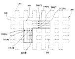
図2は、本発明の好適実施形態による光検出器205、及び光検出器205上に映される光及び陰影パターンの一部の平面図である。
【0022】
本発明のさらなる好適実施形態による光検出器205は、細長いフォトダイオードストリップのアレイである。4つのフォトダイオード210、211、212、213は、長手軸線としても周知のそれらの細長い軸線が、第1の軸線に対して平行になるように配置されており、且つ別の4つのフォトダイオード214、215、216、217は、それらの長手軸線が第2の軸線に対して平行になるように配置されている。第1の軸線に対して平行な4つのフォトダイオード210、211、212、213は、2つの対にグループ分けされており、第1の対は、第1のフォトダイオード210及び第3のフォトダイオード212によって、且つ第2の対は、第2のフォトダイオード211及び第4のフォトダイオード213によって形成されている。同様に第2の軸線に対して平行な4つのフォトダイオード214、215、216、217は、別の2つの対にグループ分けされており、第3の対は、第5のフォトダイオード214及び第7のフォトダイオード216により、且つ第4の対は、第6のフォトダイオード215及び第8のフォトダイオード217によって形成されている。第1の軸線に対して平行な第1及び第2のフォトダイオード対のフォトダイオードは、交互の順序で互いに隣接して配置されており、且つ第2の軸線に対して平行な第3及び第4のフォトダイオードも、交互の順序で互いに隣接して配置されている。
【0023】
第1及び第2の軸線は、互いに垂直になるように選択され、且つ第2の軸線に対して平行なフォトダイオード214ないし217は、フォトダイオード210ないし213に対して、フォトダイオード210ないし217がL形を形成するように配置されている。この配置は、別のIC回路のための空間を最大にするために、光検出器205を基板の隅に配置することを可能にする。
【0024】
エンコード手段は、第1の軸線に対して平行なバーの第1のセット、及びバーの第1のセットに交差する第2の軸線に対して平行なバーの第2のセットによって形成される十字形構造を有する。本発明を図1(a)に記載したエンコーダ100に類似の配置において実現するとき、エンコード手段の平行なバーの第1及び第2のセットに入射する光は、通過を妨げられ、且つ平行なバーの間の自由空間に入射する光は、エンコード手段を通って光検出器205上に通過することができる。それ故に光及び陰影のパターンは、フォトダイオード210ないし217上に映され、その際、光は、エンコード手段の自由空間を通過した光の結果として映され、且つ陰影は、平行なバーの第1及び第2のセットによってエンコード手段を通過することを妨げられた光の結果として映される。本発明を図1(b)に記載したエンコーダ120に類似の配置において実現するとき、エンコード手段におけるバーの第1及び第2のセットは、ここに入射する光を吸収する材料によってコーティングされており、且つ自由空間は、ここに入射する光を反射する反射材料によってコーティングされている。その結果、エンコード手段から反射された光は、光及び陰影のパターンを射影し、その際、光は、エンコード手段の自由空間において反射された光の結果として、且つ陰影は、エンコード手段のバーの第1及び第2のセットにおいて吸収された光の結果としてそれぞれ射影される。
【0025】
本発明の他の好適実施形態におけるエンコード手段は、板によって設けられている。板又は今後このように呼ばれるエンコード板は、ここに入射する又は通過する光が妨害されない場合に、光及び陰影の均一なパターンを映すという利点を有する。エンコード板からフォトダイオード210ないし217に映される光及び陰影のパターンは、第1の軸線に対して平行な線201の第1のセット及び第2の軸線に対して平行なバー202の第2のセットによって形成される十字形パターン204である。バー201、202の第1及び第2のセットは、エンコード板からバーのセットによって映される陰影に相当する。陰影のバー201、202の第1及び第2のセットによって囲まれた自由空間203は、エンコード板の自由空間を通過した又はこれらによって反射された光に相当する。
【0026】
この好適実施形態において利用されるそれぞれのフォトダイオードストリップの幅は、光及び陰影パターン204に所属のバー201、202の組についての幅の半分である。換言すれば、フォトダイオード対210ないし213の第1及び第2の対に属する4つのフォトダイオードストリップが、互いに隣接して配置されている時、第1及び第2のフォトダイオード210、211は、陰影内にあり、且つ第3及び第4のフォトダイオード212、213は、光内にある。それぞれのフォトダイオードストリップの長さは、4つの自由空間(開放域)203に相当する光の量を受信するように配置されている。このことは、陰影内における補償するフォトダイオードによって発生される光電流と比較して十分に大きな光電流を発生するために十分な光を受信することを確実にする。
【0027】
光及び陰影のパターン204は、いつでもフォトダイオードの対によって受信される光の量が一定であるように射影される。フォトダイオードの対のうち一方のフォトダイオードによって受信される光が増加すると、同じフォトダイオードの対における他方のフォトダイオードによって受信される光は、補償する態様で減少する。それ故にフォトダイオードの対は、補償的な形で照明されることとなる。この補償的な動作能力を表示するために、第1の軸線に対して平行なフォトダイオード210、212の第1の対及びフォトダイオード211、213の第2の対は、それぞれ記号A、A−、B及びB−によって示される。同様に第2の軸線に対して平行なフォトダイオード214、216の第3の対及びフォトダイオード215、217の第4の対は、それらの補償する動作機能を表示するために、それぞれ記号C、C−、D、D−によって示される。
【0028】
図2において、陰影は、フォトダイオード210、211、216、217上に映され、且つ光は、それぞれ補償する機能を有するフォトダイオード212、213、214、215上に映される。エンコード板の動きは、フォトダイオード210ないし217における光及び陰影のパターン204の相応する動きを引起こす。エンコード板が矢印220によって示される方向に上方及び右方に動くとき、フォトダイオード210は、光の量の増加を受け、且つフォトダイオード212は、対応して光の量の減少を受ける。エンコード板が図3に示されるような位置に動いたとき、今度は、光がフォトダイオード210、213、214、217に映され、且つ陰影は、それぞれの補償機能を有するフォトダイオード211、212、215、216上に映される。前に陰影内にあったフォトダイオード210、213、214、217が、今度は光内にあり、且つ前に光内にあったその補償機能を有するフォトダイオード211、212、215、216が、今度は陰影内にある。それ故に光が一方のフォトダイオード上に映されるとき、陰影は常に同じ対の別の補償機能を有するフォトダイオード上に映される。
【0029】
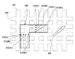
図4及び図5は、光及び陰影のパターンが矢印220の方向に動き続けたときの、フォトダイオード210ないし217上における光及び陰影のパターンを示している。光及び陰影のパターンが図5に示した位置から同じ方向220に動き続けたとき、フォトダイオード210ないし217上における光及び陰影のパターン204は、図2に示したようなパターンと同じものになる。換言すれば、サイクルは完了したものと言われ、且つ光及び陰影のパターンが同じ方向220に動き続けるならば、新しいサイクルが始まる。初期位置として、図2におけるフォトダイオード210ないし217上におけるパターンをとれば、初期位置から図3に示すような位置への光及び陰影のパターンの動きは、サイクルの1/4又は電気的な90度に相当する。同様に図2における初期位置から図4及び図5に示すような位置への光及び陰影のパターンの動きは、それぞれ電気的な180度及び270度に相当する。
【0030】
フォトダイオードは、ここに入射する光の量に比例する光電流を発生する。光がフォトダイオード上に映される場合、大きな光電流が発生される。その逆に陰影がフォトダイオード上に映される場合、わずかな光電流が発生される。フォトダイオード対210ないし217によって発生される光電流は、捕獲され且つ処理され、フォトダイオードのそれぞれの対に対して、トランジスタ・トランジスタ・ロジック(TTL)に両立するディジタル信号を発生する。
【0031】
図6は、フォトダイオード対に相当するディジタル信号を示している。第1のディジタル信号301は、第1のフォトダイオード対210、212に対応し、且つ第2のディジタル信号302は、第1の軸線に対して平行な第2のフォトダイオード対211、213に対応する。第3のディジタル信号303は、第3のフォトダイオード対215、217に対応し、且つ第4のディジタル信号304は、第2の軸線に対して平行な第4のフォトダイオード対214、216に対応する。電気的な0度における初期位置、及び図3、図4及び図5に示すような電気的な90度、180度及び270度における位置は、それぞれ状態t1、t2、t3及びt4によって表わされている。
【0032】
状態t1、t2、t3及びt4は、全体で1つの完全なサイクルを定義し、電気的な360度を表わしている。ディジタル信号301ないし304は、‘ハイ’又は‘ロー’状態のいずれかにあり、且つ信号301ないし304は、電気的な180度の期間にわたってそれぞれの状態に留まっている。
【0033】
t1の初期位置の前に、すべてのディジタル信号210ないし213は、‘ロー’状態にセットされている。t1において、第1の軸線に沿った第1の対のフォトダイオード210は陰影内にあり、その際、同じ対の他方のフォトダイオード212は光内にあり、且つそれ故にフォトダイオード210から低い光電流レベルが発生され、且つフォトダイオード212から高い光電流が発生される。t2において、光はフォトダイオード210上に映され、且つ陰影は同じ対の他方のフォトダイオード212上に映され、その結果、フォトダイオード210において、低から高への光電流レベルの遷移が生じ、且つ同時にフォトダイオード212において、高から低への光電流レベルの遷移が生じる。同じ対の両方のフォトダイオード210、212における光電流レベルのこのような同時の変化は、第1のフォトダイオード対に相当する第1のディジタル信号301にトグルを引起こす。それ故に第1のディジタル信号301は、t2において‘ハイ’状態にトグルされる。t3において、フォトダイオード210は、光内にあり、且つ同じ対の他方のフォトダイオード212は、陰影内にあり、これらは、t2におけるものと同じ状態である。それ故に対応する光電流レベルに変化は存在せず、且つ第1のディジタル信号301は、‘ハイ’状態のままである。t4において、陰影はフォトダイオード210上に映され、且つ光はフォトダイオード212上に映され、その結果、再度対応する両方の光電流に変化が生じる。これにより、第1のディジタル信号301は、t4において、‘ハイ’状態から‘ロー’状態にトグルされる。
【0034】
t1及びt2両方において、第1の軸線に対して平行な第2の対のフォトダイオード211は陰影内にあり、且つ同じ対に所属する他方のフォトダイオード213は光内にある。それ故に第2のフォトダイオード対211、213に相当する第2のディジタル信号302に変化はない。t3において、光はフォトダイオード211上に映され、且つ陰影は213上に映され、その結果、第2のフォトダイオード対211、213の光電流レベルに変化が生じる。このことは、第2のディジタル信号302を‘ロー’状態から‘ハイ’状態にトグルする。第2のディジタル信号302は、フォトダイオード対211、213の光電流レベルが変化し、その結果、第2のディジタル信号302が‘ロー’状態に戻しトグルされるt1まで、電気的に180度にわたって‘ハイ’状態のままである。
【0035】
第3及び第4のディジタル信号303、304は、前記のものと同様に、第2の軸線に沿った第3のフォトダイオード対215、217及び第4のフォトダイオード対214、216の光電流レベルによって変化する。
【0036】
ディジタル信号301ないし304が、対応するフォトダイオード対の光電流レベルにおける変化によって発生される一連のパルスからなることは、理解することができる。
【0037】
第1のフォトダイオード対210、212に対応するディジタル信号301及び第2のフォトダイオード対211、213に対応する第2のディジタル信号302は、直角位相にある。換言すれば、2つのディジタル信号301、302は、互いに電気的に90度位相ずれしている。この場合、第1のディジタル信号301は、第2のディジタル信号302を電気的に90度の位相だけ遅らせる。2つの信号301、302の間のこの位相シフトは、第1の軸線に対して平行なエンコード板の動きの方向に関する情報を提供する。エンコード板が第1の軸線に対して平行に反対の方向に動くと、ディジタル信号301、302の間の対応する位相シフトは、反対方向にあり、すなわち第2のディジタル信号302は、第1のディジタル信号301を電気的に90度だけ遅らせる。
【0038】
同様に第3のフォトダイオード対215、217に対応する第3のディジタル信号303及び第4のフォトダイオード対214、216に対応する第4のディジタル信号304は、直角位相にある。この場合、第3のディジタル信号303は、第4のディジタル信号304を電気的に90度の位相だけ遅らせる。2つのディジタル信号303、304の間のこの位相シフトは、第2の軸線に対して平行なエンコード板の動きの方向に関する情報を提供する。エンコード板が第2の軸線に対して平行に反対の方向に動くと、ディジタル信号303、304の間の対応する位相シフトは、反対方向にある。
【0039】
図7は、本発明によるフォトダイオードから変位情報を処理し且つ取得するための装置を示している。
【0040】
第1及び第2のフォトダイオード対210ないし213からの光電流401は、第1の信号処理ユニット402において処理される。第1の信号処理ユニット402は、それぞれのフォトダイオード210ないし213からの光電流レベル401の変化を検出し、第1の軸線に対して平行に配置された第1及び第2のフォトダイオード対に対応する直角位相信号301、302の対を出力する。第1の方向識別ユニット403は、直角位相信号301、302の対の間の位相差を検出し、且つ光パターンの動きの方向を表示する方向出力信号405を供給する。パルス出力404も、第1の方向識別ユニット403によって発生され、このパルス出力は、直角位相信号301、302のサイクルの数に比例する。パルス出力404は、第1の軸線に対して平行な光パターンの変位の大きさに関する情報を提供する。
【0041】
第1の計数ユニット406は、第1の方向識別ユニット403からのパルス出力404のパルスの数を計数し、且つ光パターンの変位の大きさを判定する。方向出力信号405も、第1の計数ユニット406に供給されるので、第1の軸線に沿った光パターンの変位は判定することができ、且つ符号を有する2進法407において表わされる。
【0042】
同様に第3及び第4のフォトダイオード対214ないし217からの光電流414は、第2の信号処理ユニット413において処理される。第2の信号処理ユニット413は、それぞれのフォトダイオード214ないし217からの光電流レベル414の変化を検出し、第2の軸線に対して平行に配置された第3及び第4のフォトダイオード対に対応する直角位相信号303、304の対を出力する。第2の方向識別ユニット412は、直角位相信号303、304の対の位相差を検出し、且つ光パターンの動きの方向を表示する方向出力信号411を発生する。パルス出力410も、第2の方向識別ユニット412によって発生され、このパルス出力は、直角位相信号303、304のサイクルの数に比例する。パルス出力410は、第2の軸線に対して平行な光パターンの変位の大きさに関する情報を供給する。
【0043】
第2の計数ユニット409は、第2の方向識別ユニット412からのパルス出力410のパルスの数を計数し、且つ光パターンの変位の大きさを判定する。方向出力信号411も、第2の計数ユニット409に供給されるので、第2の軸線に沿った光パターンの変位は判定することができ、且つ符号付き2進数408において表わされる。
【0044】
リセット信号415は、出力パルス404、410の計数が初めから始まるように、第1の計数ユニット406及び第2の計数ユニット409の両方のために設けられており、すなわち第1及び第2両方の軸線に沿った変位は、ゼロにリセットされる。リセット信号415は、新しい初期位置から新しい変位を判定しようとするときに使用されることができる。
【0045】
第1の計数ユニット406から符号を有する2進法407によって表わされる第1の軸線に対して平行な変位、及び第2の計数ユニット409から符号付き2進数408によって表わされる第2の軸線に対して平行な変位は、光のパターンの2次元変位情報を提供し、この情報は、エンコード板の変位に直接比例している。したがってエンコード板が接続された実際の装置の変位は、直接又は間接的に判定することができる。
【0046】
前記の好適実施形態は、第1の軸線に対して平行に配置された2つのフォトダイオード対、及び第2の軸線に対して平行に配置された別の2つのフォトダイオード対からなる。別の態様において、フォトダイオード対は、それぞれの軸線に対して平行なフォトダイオード対のさまざまなサイクルを相互に配置することによって拡張することができる。換言すれば、更に第5及び第6のフォトダイオード対を、第1の軸線に対して平行に配置することができ、その結果、フォトダイオードの4つの対が生じる。第1の対及び第5のフォトダイオード対は、同じ光及び陰影のパターンを受信し、且つ同様に第2の対及び第6のフォトダイオード対は、同じ光及び陰影のパターンを受信する。それ故に第5及び第6のフォトダイオード対によって発生される直角位相信号は、第1及び第2のフォトダイオード対によって発生される直角位相信号と同一である。フォトダイオード又はエンコード板の一部が損傷したとき、対応するフォトダイオード対の直角位相信号は、変位情報を補償するために使用することができる。したがってこの別の態様による構成は、感知装置の丈夫さを増加する。同様に第7及び第8のフォトダイオード対を、第2の軸線に対して平行に配置してもよく、その結果、同じ理由のために第2の軸線に対して平行な4つのフォトダイオード対が生じる。
【0047】
しかしながらこの別の態様における光学位置感知装置のために必要な空間は、必要なフォトダイオードの数が少なくとも2倍であるために増加する。
【0048】
本発明の前記の態様を説明したが、これらは、本発明の基本方式の単なる例示であり、本発明の範囲内で更に様々な変形・変更が可能である。
【0049】
即ち、本発明は、第1の軸線に対して平行に配置された第1の光センサ(210、211、212、213)、 第2の軸線に対して平行に配置された第2の光センサ(214、215、216、217)及び、光及び陰影からなるパターンが、前記光センサ上に映されるように、前記光センサに入射する光の経路に干渉するエンコード手段を含む2次元変位を感知する光学位置感知装置において、前記第1及び第2の軸線が互いに所定の角度で交差しており、前記エンコード手段及び前記光センサが相互の位置を変更可能とされ、その結果光センサによって受信される光の変調を生じ、前記エンコード手段が、前記第1の軸線に対して平行な方向に相対的に動いたとき、前記第2の光センサによって受信される光の前記変調が、前記第1の光センサによって受信される光の前記変調より大きく、且つ前記エンコード手段が、前記第2の軸線に対して平行な方向に相対的に動いたとき、前記第1の光センサによって受信される光の前記変調が、前記第2の光センサによって受信される光の前記変調より大きくなりように配置されることを特徴とする光学位置感知装置を提供する。
【0050】
好ましくは、前記第1の光センサが、光検出器の第1の対及び第2の対を形成する4つの光検出器からなり、且つ前記第2の光センサが、光検出器の第3の対及び第4の対を形成する4つの光検出器からなる光学位置感知装置において、光検出器のそれぞれの対によって受信される光の合計量が実質的に変わらないように、前記エンコード手段及び前記光検出器対が配置されており、且つ1つの光検出器対の1つの光検出器によって受信された前記光が、前記エンコード手段の移動のために増加したとき、同じ光検出器対の別の光検出器により受信される前記光が、補償する態様で減少する。
【0051】
好ましくは、前記第1の軸線に対して平行な前記光検出器の前記第1及び第2の対に所属する前記光検出器が、隣接し且つ互いに交互に配置されている。
【0052】
好ましくは、前記第2の軸線に対して平行な前記光検出器の前記第3及び第4の対に所属する前記光検出器が、隣接し且つ互いに交互に配置されている。
【0053】
好ましくは、前記エンコード手段が、前記第1の軸線に対して平行に配置された平行なバーの第1のセット、及び前記第2の軸線に対して平行に配置された平行なバーの第2のセットからなり、バーの前記第2のセットが、バーの前記第1のセットに交差し、十字形構造を形成している。
【0054】
好ましくは、平行なバーの前記第1のセットが、同じ幅を有し、且つ互いに前記幅に等しい距離を置いて均等に離れている。
【0055】
好ましくは、平行なバーの前記第2のセットが、同じ幅を有し、且つ互いに前記幅に等しい距離を置いて均等に離れている。
【0056】
好ましくは、平行なバーの前記第1及び第2のセットの幅が、同じである。
【0057】
好ましくは、前記エンコード手段が、板の形に設けられている。
【0058】
好ましくは、前記第1の軸線及び前記第2の軸線が、互いに垂直である。
【図面の簡単な説明】
【図1】(a)は、光学エンコーダの横断面図であり、(b)は、反射光学エンコーダの横断面図である。
【図2】本発明による光検出器及び光検出器上に映されるエンコード板のパターンの一部の平面図である。
【図3】本発明による上方向及び右方向に向かってエンコード板が動くときに光検出器上に映される光及び陰影のパターンの順序を示す図である。
【図4】本発明による上方向及び右方向に向かってエンコード板が動くときに光検出器上に映される光及び陰影のパターンの順序を示す図である。
【図5】本発明による上方向及び右方向に向かってエンコード板が動くときに光検出器上に映される光及び陰影のパターンの順序を示す図である。
【図6】本発明による板の動きの結果としてフォトダイオード対の直角位相出力を示す図である。
【図7】本発明による第1及び第2の軸線に沿った変位に関する情報を処理し且つ取得するための装置を示す図である。
【符号の説明】
100 光学エンコーダ
101 光放出器
102 光検出器
103 コードホイール
204 光及び陰影のパターン
205 光検出器
210 フォトダイオード
211 フォトダイオード
212 フォトダイオード
213 フォトダイオード
214 フォトダイオード
215 フォトダイオード
216 フォトダイオード
217 フォトダイオード[0001]
TECHNICAL FIELD OF THE INVENTION
The present invention relates to an optical position sensing device capable of determining a displacement along a two-dimensional plane.
[0002]
[Prior art]
An encoder is a device that provides feedback information to a closed loop system. The encoder enables the interpretation of the signals so as to obtain information about position, velocity, acceleration and / or the like when the encoder operates in pairs with a code wheel or codestrip. Code wheels / code strips consist of a regular pattern of slots or bars. Depending on the position of the slots and bars, the code wheels / code strips allow or block the passage of light. The photodetector detects light transmitted by the codewheel / codestrip and provides explicit information about codewheel / codestrip movement based on the detected light signal.
[0003]
FIG. 1A shows a cross section of a typical
[0004]
A
[0005]
FIG. 1B shows a cross section of a typical reflective
[0006]
The
[0007]
The outputs of the photodetectors in both encoders, the photocurrent, are usually processed in an analog signal processor to generate an analog signal, and the analog signal is subsequently passed to an analog-to-digital converter (ADC). Generates a digital output and provides information regarding the magnitude and direction of displacement of the codewheel and of the device to which the codewheel is coupled.
[0008]
ADC circuits are usually very large and require a large number of discrete output levels to represent displacement. Therefore, depending on the number of required power levels, a separate range of the reference threshold is required to set a discrimination between the power levels. The reference threshold is adapted to allow any change in the photocurrent level due to a change in the brightness of the light source, in particular the light emitter. The reference threshold must allow for any changes in the photodetector manufacturing process, degradation of any equipment utilized, and all other transient factors such as temperature shifts.
[0009]
To solve the above problems, optical rotary pulse generating encoders with quadrature output are commonly used as digital optical encoders. In an optical rotary pulse generating encoder having a quadrature output, the photodetector usually comprises a plurality of sets of photodiodes as photodetectors, and the photocurrent generated in the photodiodes is compensated by a signal processing circuit through a compensating analog Provided to generate multiple pairs of signals. These pairs of compensated analog signals are further processed, for example, in a comparator circuit, to generate a pair of digital output signals in quadrature. The magnitude and direction of the displacement can be extracted from the quadrature output signal pair to provide displacement information from the initial position.
[0010]
The HEDR-8000 series optical encoder manufactured and sold by the present applicant has a configuration similar to the
[0011]
[Patent Document 1] JP-A-2003-50142
[Patent Document 2] JP-A-2000-283795
[Patent Document 3] JP-A-6-221874
[Patent Document 4] JP-A-5-187890
[0012]
[Problems to be solved by the invention]
The output signal generated by either the aforementioned quadrature output encoder or an optical encoder manufactured and sold by the applicant provides information only about displacement along a single axis, i.e., for a single axis application. I can't. For two-axis applications such as detecting the movement of a mouse trackball, the need for two separate optical rotation pulse generating encoders to provide mouse displacement information along two axes or on a two-dimensional plane is needed. Yes, as a result, the prior art requires more components and a larger working space for the encoder, thus increasing manufacturing costs. Therefore, there is a need for an efficient digital optical position sensing device for sensing two-dimensional displacement.
[0013]
[Means for Solving the Problems]
According to the present invention, an optical position sensing device for sensing a two-dimensional displacement is provided. The optical position sensing device comprises a first optical sensor arranged parallel to a first axis and a second optical sensor arranged parallel to a second axis, wherein the first And a second axis extends in a direction intersecting with each other, and a pattern composed of light and a shadow serves as an encoding unit that interferes with a path of light incident on the optical sensor as reflected on the optical sensor. In this case, the encoding means and the optical sensor are movable with respect to each other, so that the modulation of the light received by the optical sensor takes place and is arranged in the device as follows. That is, when the encoding means moves relatively in a direction parallel to the first axis, the modulation of the light received by the second optical sensor changes the modulation of the light received by the first optical sensor. When the encoding means moves relatively larger and in a direction parallel to the second axis, the modulation of the light received by the first light sensor changes the light received by the second light sensor. Greater than the modulation.
[0014]
Light is emitted by the light source, for example by a light emitter, onto the light sensor, and the encoding means is used to interfere with the path of light from the light emitter to the light sensor. Depending on the amount of interference of the light path by the encoding means, a corresponding light output signal proportional to the amount of incident light, in particular a photocurrent, is generated from the respective light sensor.
[0015]
The optical position sensor according to the present invention processes the change in photocurrent generated by the optical sensor parallel to the first and second axes and obtains information on the magnitude of the displacement, for example, the frequency, Two-dimensional displacement can be detected. In conventional systems, such two-dimensional displacement information requires two separate encoders.
[0016]
BEST MODE FOR CARRYING OUT THE INVENTION
Next, preferred embodiments of the present invention will be described in detail with reference to the accompanying drawings.
[0017]
A digital optical position sensing device according to a preferred embodiment of the present invention comprises two pairs of photodetectors arranged parallel to a first axis, a pair of photodetectors arranged parallel to a second axis. It consists of two different pairs, the first and second axes intersect obliquely with each other. The encoding means, which interferes with the path of the light incident on the photodetector, is such that light and shading patterns are projected on the photodetector.
[0018]
The encoding means and the four pairs of photodetectors are arranged such that the total amount of light received by each pair of photodetectors does not change, and due to the movement of the encoding means, of the pair of photodetectors. As the light received by one of the photodetectors increases, the light received by the other photodetector of the same pair of photodetectors decreases in a compensating manner.
[0019]
In this regard, the optical position sensing device according to the present invention can be configured similarly to the
[0020]
Further, the optical position sensing device according to the present invention can be configured similarly to the
[0021]
FIG. 2 is a plan view of a
[0022]
[0023]
The first and second axes are selected to be perpendicular to each other, and the
[0024]
The encoding means is formed by a first set of bars parallel to the first axis and a second set of bars parallel to a second axis intersecting the first set of bars. It has a letter-shaped structure. When implementing the present invention in an arrangement similar to the
[0025]
The encoding means in another preferred embodiment of the present invention is provided by a plate. The plate or encoding plate, henceforth referred to as such, has the advantage of displaying a uniform pattern of light and shading when the light entering or passing through it is unobstructed. The light and shading pattern projected from the encoding plate onto the photodiodes 210-217 includes a first set of
[0026]
The width of each photodiode strip utilized in this preferred embodiment is half the width for the set of
[0027]
The light and
[0028]
In FIG. 2, the shadows are projected on
[0029]
4 and 5 show the light and shade patterns on the
[0030]
The photodiode generates a photocurrent proportional to the amount of light incident thereon. When light is projected on a photodiode, a large photocurrent is generated. Conversely, if a shadow is cast on the photodiode, a small photocurrent is generated. The photocurrent generated by the photodiode pairs 210-217 is captured and processed to generate a transistor-to-transistor logic (TTL) compatible digital signal for each pair of photodiodes.
[0031]
FIG. 6 shows a digital signal corresponding to a photodiode pair. The first
[0032]
State t 1 , T 2 , T 3 And t 4 Defines a complete cycle as a whole and represents 360 electrical degrees. Digital signals 301-304 are in either a "high" or "low" state, and signals 301-304 remain in their respective states for an electrical 180 degree period.
[0033]
t 1 Prior to the initial position, all digital signals 210-213 have been set to a "low" state. t 1 The first pair of
[0034]
t 1 And t 2 In both, a second pair of
[0035]
The third and fourth
[0036]
It can be seen that the digital signals 301-304 consist of a series of pulses generated by a change in the photocurrent level of the corresponding photodiode pair.
[0037]
The
[0038]
Similarly, the third
[0039]
FIG. 7 shows an apparatus for processing and obtaining displacement information from a photodiode according to the present invention.
[0040]
[0041]
The
[0042]
Similarly,
[0043]
The
[0044]
The
[0045]
A displacement parallel to a first axis represented by a signed
[0046]
The preferred embodiment described above consists of two pairs of photodiodes arranged parallel to the first axis and another two pairs of photodiodes arranged parallel to the second axis. In another aspect, the photodiode pairs can be extended by interleaving various cycles of the photodiode pairs parallel to their respective axes. In other words, further fifth and sixth pairs of photodiodes can be arranged parallel to the first axis, resulting in four pairs of photodiodes. The first and fifth pairs of photodiodes receive the same light and shade pattern, and similarly the second and sixth pairs of photodiodes receive the same light and shade pattern. Therefore, the quadrature signals generated by the fifth and sixth pairs of photodiodes are identical to the quadrature signals generated by the first and second pairs of photodiodes. When a photodiode or a portion of the encoding plate is damaged, the quadrature signal of the corresponding photodiode pair can be used to compensate for the displacement information. Thus, the configuration according to this alternative aspect increases the robustness of the sensing device. Similarly, the seventh and eighth pairs of photodiodes may be arranged parallel to the second axis, so that for the same reason the four pairs of photodiodes parallel to the second axis. Occurs.
[0047]
However, the space required for the optical position sensing device in this alternative is increased because the number of photodiodes required is at least twice.
[0048]
Although the above embodiments of the present invention have been described, these are merely examples of the basic system of the present invention, and various modifications and changes can be made within the scope of the present invention.
[0049]
That is, the present invention provides a first optical sensor (210, 211, 212, 213) arranged parallel to a first axis, and a second optical sensor arranged parallel to a second axis. (214, 215, 216, 217) and a two-dimensional displacement including an encoding unit that interferes with a path of light incident on the optical sensor so that a pattern composed of light and shadow is reflected on the optical sensor. In the optical position sensing device for sensing, the first and second axes intersect each other at a predetermined angle, and the encoding means and the optical sensor can change their positions with each other, so that the optical sensor receives the light. And the modulation of the light received by the second optical sensor when the encoding means moves relatively in a direction parallel to the first axis. Light of one Greater than the modulation of the light received by the sensor, and when the encoding means moves relative to the direction parallel to the second axis, the light received by the first light sensor An optical position sensing device is provided, wherein the modulation is arranged to be greater than the modulation of the light received by the second light sensor.
[0050]
Preferably, the first photosensor comprises four photodetectors forming a first pair and a second pair of photodetectors, and the second photosensor is a third photodetector of the photodetectors. And a fourth pair of photodetectors forming a fourth pair, the encoding means such that the total amount of light received by each pair of photodetectors does not substantially change. And the photodetector pair is arranged, and when the light received by one photodetector of one photodetector pair increases due to movement of the encoding means, the same photodetector pair The light received by another of the light detectors is reduced in a compensating manner.
[0051]
Preferably, the photodetectors belonging to the first and second pairs of photodetectors parallel to the first axis are arranged adjacently and alternately with each other.
[0052]
Preferably, said photodetectors belonging to said third and fourth pairs of said photodetectors parallel to said second axis are adjacent and alternate with each other.
[0053]
Preferably, said encoding means comprises a first set of parallel bars arranged parallel to said first axis and a second set of parallel bars arranged parallel to said second axis. And the second set of bars intersects the first set of bars to form a cruciform structure.
[0054]
Preferably, said first set of parallel bars have the same width and are evenly separated from one another by a distance equal to said width.
[0055]
Preferably, said second set of parallel bars have the same width and are evenly separated from one another by a distance equal to said width.
[0056]
Preferably, the widths of said first and second sets of parallel bars are the same.
[0057]
Preferably, said encoding means is provided in the form of a plate.
[0058]
Preferably, the first axis and the second axis are perpendicular to each other.
[Brief description of the drawings]
1A is a cross-sectional view of an optical encoder, and FIG. 1B is a cross-sectional view of a reflective optical encoder.
FIG. 2 is a plan view of a photodetector according to the present invention and a part of a pattern of an encoding plate projected on the photodetector.
FIG. 3 is a diagram illustrating the order of light and shade patterns projected on a photodetector when an encoding plate moves upward and to the right according to the present invention;
FIG. 4 is a diagram illustrating the order of light and shadow patterns projected on a photodetector when an encoding plate moves upward and rightward according to the present invention.
FIG. 5 is a diagram illustrating the order of light and shadow patterns projected on a photodetector when an encoding plate moves upward and to the right according to the present invention;
FIG. 6 shows the quadrature output of a photodiode pair as a result of plate movement according to the present invention.
FIG. 7 illustrates an apparatus for processing and obtaining information regarding displacement along first and second axes according to the present invention.
[Explanation of symbols]
100 Optical encoder
101 light emitter
102 Photodetector
103 Code Wheel
204 Light and Shading Patterns
205 photodetector
210 Photodiode
211 Photodiode
212 Photodiode
213 Photodiode
214 Photodiode
215 Photodiode
216 Photodiode
217 Photodiode
Claims (10)
第2の軸線に対して平行に配置された第2の光センサ(214、215、216、217)及び
光及び陰影からなるパターンが、前記光センサ上に映されるように、前記光センサに入射する光の経路に干渉するエンコード手段を含む2次元変位を感知する光学位置感知装置において、
前記第1及び第2の軸線が互いに所定の角度で交差しており、前記エンコード手段及び前記光センサが相互の位置を変更可能とされ、その結果光センサによって受信される光の変調を生じ、
前記エンコード手段が、前記第1の軸線に対して平行な方向に相対的に動いたとき、前記第2の光センサによって受信される光の前記変調が、前記第1の光センサによって受信される光の前記変調より大きく、且つ
前記エンコード手段が、前記第2の軸線に対して平行な方向に相対的に動いたとき、前記第1の光センサによって受信される光の前記変調が、前記第2の光センサによって受信される光の前記変調より大きくなりように配置されることを特徴とする光学位置感知装置。A first optical sensor (210, 211, 212, 213) disposed parallel to the first axis;
A second optical sensor (214, 215, 216, 217) arranged parallel to the second axis and a pattern composed of light and shade are applied to the optical sensor so that the pattern is projected on the optical sensor. An optical position sensing device that senses a two-dimensional displacement including encoding means that interferes with the path of incident light,
Said first and second axes intersect each other at a predetermined angle, said encoding means and said optical sensor are capable of changing their position with respect to each other, resulting in a modulation of the light received by the optical sensor;
The modulation of the light received by the second light sensor is received by the first light sensor when the encoding means moves relatively in a direction parallel to the first axis. The modulation of light received by the first optical sensor is greater than the modulation of light and when the encoding means moves relatively in a direction parallel to the second axis, the modulation of the light An optical position sensing device arranged to be greater than said modulation of light received by said two optical sensors.
前記第2の光センサが、光検出器の第3の対及び第4の対を形成する4つの光検出器からなる光学位置感知装置において、
光検出器のそれぞれの対によって受信される光の合計量が実質的に変わらないように、前記エンコード手段及び前記光検出器対が配置されており且つ
1つの光検出器対の1つの光検出器によって受信された前記光が、前記エンコード手段の移動のために増加したとき、同じ光検出器対の別の光検出器により受信される前記光が、補償する態様で減少することを特徴とする請求項1に記載の光学位置感知装置。The first photosensor comprises four photodetectors forming a first pair and a second pair of photodetectors, and the second photosensor comprises a third pair of photodetectors and An optical position sensing device comprising four photodetectors forming a fourth pair,
The encoding means and the photodetector pair are arranged and one photodetector of one photodetector pair such that the total amount of light received by each pair of photodetectors does not substantially change. Wherein the light received by another photodetector of the same photodetector pair decreases in a compensating manner when the light received by a detector increases due to movement of the encoding means. The optical position sensing device according to claim 1.
Applications Claiming Priority (1)
| Application Number | Priority Date | Filing Date | Title |
|---|---|---|---|
| MYPI20022390 | 2002-06-25 |
Publications (2)
| Publication Number | Publication Date |
|---|---|
| JP2004029019A true JP2004029019A (en) | 2004-01-29 |
| JP2004029019A5 JP2004029019A5 (en) | 2006-08-10 |
Family
ID=29728821
Family Applications (1)
| Application Number | Title | Priority Date | Filing Date |
|---|---|---|---|
| JP2003174211A Pending JP2004029019A (en) | 2002-06-25 | 2003-06-19 | Optical position sensing device |
Country Status (2)
| Country | Link |
|---|---|
| US (2) | US7057163B2 (en) |
| JP (1) | JP2004029019A (en) |
Cited By (2)
| Publication number | Priority date | Publication date | Assignee | Title |
|---|---|---|---|---|
| EP2060953A1 (en) | 2007-11-09 | 2009-05-20 | Canon Kabushiki Kaisha | Colour image forming apparatus with registration correction |
| JP2018128413A (en) * | 2017-02-10 | 2018-08-16 | 信得 曾 | Optical scanning light guide encoder |
Families Citing this family (2)
| Publication number | Priority date | Publication date | Assignee | Title |
|---|---|---|---|---|
| US7521719B2 (en) * | 2004-08-13 | 2009-04-21 | Paul Steven Schranz | Light emitting and image sensing device and apparatus |
| DE102005045713A1 (en) * | 2005-09-24 | 2007-03-29 | Braun Gmbh | Electric hair removal device |
Citations (7)
| Publication number | Priority date | Publication date | Assignee | Title |
|---|---|---|---|---|
| JPS61292016A (en) * | 1985-06-19 | 1986-12-22 | Yokogawa Hewlett Packard Ltd | Optical position encoder |
| JPS63148856A (en) * | 1986-12-10 | 1988-06-21 | Kobatoron:Kk | Linear motor |
| JPS63148855A (en) * | 1986-12-11 | 1988-06-21 | Advantest Corp | Position detector for x-y linear motor |
| JPH01272917A (en) * | 1988-04-25 | 1989-10-31 | Mitsutoyo Corp | Reflection type xy encoder |
| JPH0519981U (en) * | 1991-08-27 | 1993-03-12 | エスエムケイ株式会社 | Photoelectric sensor for optical scanner |
| JP2001208566A (en) * | 1999-12-03 | 2001-08-03 | Renishaw Plc | Measuring apparatus |
| JP2002048601A (en) * | 2000-08-07 | 2002-02-15 | Mitsutoyo Corp | Optical displacement measuring device |
Family Cites Families (4)
| Publication number | Priority date | Publication date | Assignee | Title |
|---|---|---|---|---|
| US3297879A (en) * | 1963-03-18 | 1967-01-10 | W & L E Gurley | Optical encoder responsive to movement in two directions |
| US4409479A (en) * | 1981-12-03 | 1983-10-11 | Xerox Corporation | Optical cursor control device |
| US4893071A (en) * | 1988-05-24 | 1990-01-09 | American Telephone And Telegraph Company, At&T Bell Laboratories | Capacitive incremental position measurement and motion control |
| CH685214A5 (en) * | 1991-10-15 | 1995-04-28 | Hans Ulrich Meyer | capacitive sensor position. |
-
2003
- 2003-04-28 US US10/424,271 patent/US7057163B2/en not_active Expired - Lifetime
- 2003-06-19 JP JP2003174211A patent/JP2004029019A/en active Pending
-
2006
- 2006-05-17 US US11/436,337 patent/US7238932B2/en not_active Expired - Lifetime
Patent Citations (7)
| Publication number | Priority date | Publication date | Assignee | Title |
|---|---|---|---|---|
| JPS61292016A (en) * | 1985-06-19 | 1986-12-22 | Yokogawa Hewlett Packard Ltd | Optical position encoder |
| JPS63148856A (en) * | 1986-12-10 | 1988-06-21 | Kobatoron:Kk | Linear motor |
| JPS63148855A (en) * | 1986-12-11 | 1988-06-21 | Advantest Corp | Position detector for x-y linear motor |
| JPH01272917A (en) * | 1988-04-25 | 1989-10-31 | Mitsutoyo Corp | Reflection type xy encoder |
| JPH0519981U (en) * | 1991-08-27 | 1993-03-12 | エスエムケイ株式会社 | Photoelectric sensor for optical scanner |
| JP2001208566A (en) * | 1999-12-03 | 2001-08-03 | Renishaw Plc | Measuring apparatus |
| JP2002048601A (en) * | 2000-08-07 | 2002-02-15 | Mitsutoyo Corp | Optical displacement measuring device |
Cited By (3)
| Publication number | Priority date | Publication date | Assignee | Title |
|---|---|---|---|---|
| EP2060953A1 (en) | 2007-11-09 | 2009-05-20 | Canon Kabushiki Kaisha | Colour image forming apparatus with registration correction |
| US8064810B2 (en) | 2007-11-09 | 2011-11-22 | Canon Kabushiki Kaisha | Image forming apparatus with image bearing member adjustment |
| JP2018128413A (en) * | 2017-02-10 | 2018-08-16 | 信得 曾 | Optical scanning light guide encoder |
Also Published As
| Publication number | Publication date |
|---|---|
| US20030234352A1 (en) | 2003-12-25 |
| US7057163B2 (en) | 2006-06-06 |
| US20070007446A1 (en) | 2007-01-11 |
| US7238932B2 (en) | 2007-07-03 |
Similar Documents
| Publication | Publication Date | Title |
|---|---|---|
| US20070018086A1 (en) | Optical Encoder | |
| EP0843159A2 (en) | Opto-electronic scale-reading apparatus | |
| JP4951884B2 (en) | Encoder device | |
| JP5200550B2 (en) | Detection unit and encoder | |
| US6828548B1 (en) | Optical displacement measuring device | |
| US7238932B2 (en) | Optical position sensing device | |
| US7026604B2 (en) | Vernier-scaled high-resolution encoder | |
| GB2430250A (en) | Optical encoder and method therefor | |
| JP2007071732A (en) | Absolute value encoder of optical type | |
| JP2001208567A (en) | Optical encoder for quantitative detection of linear motion or rotational motion | |
| JP2007183116A (en) | Optical encoder | |
| US6759647B2 (en) | Projection encoder | |
| JP6684087B2 (en) | Optical encoder | |
| JP2013036945A (en) | Origin detecting method of optical encoder | |
| CN113302454A (en) | Encoder apparatus | |
| JP5979033B2 (en) | Encoder | |
| JP2000321097A (en) | Optical encoder | |
| JP2007078693A (en) | Transmissive optical encoder | |
| JP2003279384A (en) | Optical absolute-value encoder and moving device | |
| JP2003075200A (en) | Pulse signal generating system and method | |
| JP2004163302A (en) | Optical encoder | |
| JPS6129718A (en) | Photoelectric transmission type encoder | |
| JP2003075199A (en) | Pulse signal generating system and method | |
| JPH04232814A (en) | High-resolution absolute value encoder | |
| WO1994025830A1 (en) | Opto-electronic scale reading apparatus |
Legal Events
| Date | Code | Title | Description |
|---|---|---|---|
| RD03 | Notification of appointment of power of attorney |
Free format text: JAPANESE INTERMEDIATE CODE: A7423 Effective date: 20060616 |
|
| A521 | Request for written amendment filed |
Free format text: JAPANESE INTERMEDIATE CODE: A523 Effective date: 20060619 |
|
| A621 | Written request for application examination |
Free format text: JAPANESE INTERMEDIATE CODE: A621 Effective date: 20060619 |
|
| A711 | Notification of change in applicant |
Free format text: JAPANESE INTERMEDIATE CODE: A711 Effective date: 20070326 |
|
| A977 | Report on retrieval |
Free format text: JAPANESE INTERMEDIATE CODE: A971007 Effective date: 20081211 |
|
| A131 | Notification of reasons for refusal |
Free format text: JAPANESE INTERMEDIATE CODE: A131 Effective date: 20081216 |
|
| A521 | Request for written amendment filed |
Free format text: JAPANESE INTERMEDIATE CODE: A523 Effective date: 20090316 |
|
| A02 | Decision of refusal |
Free format text: JAPANESE INTERMEDIATE CODE: A02 Effective date: 20090407 |
|
| A521 | Request for written amendment filed |
Free format text: JAPANESE INTERMEDIATE CODE: A523 Effective date: 20091022 |
|
| A521 | Request for written amendment filed |
Free format text: JAPANESE INTERMEDIATE CODE: A523 Effective date: 20110530 |