JP2004021893A - Portable information communication terminal, program and recording medium recording program - Google Patents
Portable information communication terminal, program and recording medium recording program Download PDFInfo
- Publication number
- JP2004021893A JP2004021893A JP2002179563A JP2002179563A JP2004021893A JP 2004021893 A JP2004021893 A JP 2004021893A JP 2002179563 A JP2002179563 A JP 2002179563A JP 2002179563 A JP2002179563 A JP 2002179563A JP 2004021893 A JP2004021893 A JP 2004021893A
- Authority
- JP
- Japan
- Prior art keywords
- item
- group
- communication terminal
- list information
- list
- Prior art date
- Legal status (The legal status is an assumption and is not a legal conclusion. Google has not performed a legal analysis and makes no representation as to the accuracy of the status listed.)
- Pending
Links
Images


Classifications
-
- G—PHYSICS
- G06—COMPUTING; CALCULATING OR COUNTING
- G06F—ELECTRIC DIGITAL DATA PROCESSING
- G06F3/00—Input arrangements for transferring data to be processed into a form capable of being handled by the computer; Output arrangements for transferring data from processing unit to output unit, e.g. interface arrangements
- G06F3/01—Input arrangements or combined input and output arrangements for interaction between user and computer
- G06F3/048—Interaction techniques based on graphical user interfaces [GUI]
- G06F3/0481—Interaction techniques based on graphical user interfaces [GUI] based on specific properties of the displayed interaction object or a metaphor-based environment, e.g. interaction with desktop elements like windows or icons, or assisted by a cursor's changing behaviour or appearance
- G06F3/0482—Interaction with lists of selectable items, e.g. menus
-
- G—PHYSICS
- G06—COMPUTING; CALCULATING OR COUNTING
- G06F—ELECTRIC DIGITAL DATA PROCESSING
- G06F1/00—Details not covered by groups G06F3/00 - G06F13/00 and G06F21/00
- G06F1/16—Constructional details or arrangements
- G06F1/1613—Constructional details or arrangements for portable computers
- G06F1/1615—Constructional details or arrangements for portable computers with several enclosures having relative motions, each enclosure supporting at least one I/O or computing function
- G06F1/1616—Constructional details or arrangements for portable computers with several enclosures having relative motions, each enclosure supporting at least one I/O or computing function with folding flat displays, e.g. laptop computers or notebooks having a clamshell configuration, with body parts pivoting to an open position around an axis parallel to the plane they define in closed position
-
- G—PHYSICS
- G06—COMPUTING; CALCULATING OR COUNTING
- G06F—ELECTRIC DIGITAL DATA PROCESSING
- G06F1/00—Details not covered by groups G06F3/00 - G06F13/00 and G06F21/00
- G06F1/16—Constructional details or arrangements
- G06F1/1613—Constructional details or arrangements for portable computers
- G06F1/1626—Constructional details or arrangements for portable computers with a single-body enclosure integrating a flat display, e.g. Personal Digital Assistants [PDAs]
-
- G—PHYSICS
- G06—COMPUTING; CALCULATING OR COUNTING
- G06F—ELECTRIC DIGITAL DATA PROCESSING
- G06F1/00—Details not covered by groups G06F3/00 - G06F13/00 and G06F21/00
- G06F1/16—Constructional details or arrangements
- G06F1/1613—Constructional details or arrangements for portable computers
- G06F1/1633—Constructional details or arrangements of portable computers not specific to the type of enclosures covered by groups G06F1/1615 - G06F1/1626
- G06F1/1684—Constructional details or arrangements related to integrated I/O peripherals not covered by groups G06F1/1635 - G06F1/1675
-
- G—PHYSICS
- G06—COMPUTING; CALCULATING OR COUNTING
- G06F—ELECTRIC DIGITAL DATA PROCESSING
- G06F3/00—Input arrangements for transferring data to be processed into a form capable of being handled by the computer; Output arrangements for transferring data from processing unit to output unit, e.g. interface arrangements
- G06F3/01—Input arrangements or combined input and output arrangements for interaction between user and computer
- G06F3/03—Arrangements for converting the position or the displacement of a member into a coded form
- G06F3/033—Pointing devices displaced or positioned by the user, e.g. mice, trackballs, pens or joysticks; Accessories therefor
- G06F3/0362—Pointing devices displaced or positioned by the user, e.g. mice, trackballs, pens or joysticks; Accessories therefor with detection of 1D translations or rotations of an operating part of the device, e.g. scroll wheels, sliders, knobs, rollers or belts
-
- G—PHYSICS
- G06—COMPUTING; CALCULATING OR COUNTING
- G06F—ELECTRIC DIGITAL DATA PROCESSING
- G06F3/00—Input arrangements for transferring data to be processed into a form capable of being handled by the computer; Output arrangements for transferring data from processing unit to output unit, e.g. interface arrangements
- G06F3/01—Input arrangements or combined input and output arrangements for interaction between user and computer
- G06F3/048—Interaction techniques based on graphical user interfaces [GUI]
- G06F3/0484—Interaction techniques based on graphical user interfaces [GUI] for the control of specific functions or operations, e.g. selecting or manipulating an object, an image or a displayed text element, setting a parameter value or selecting a range
- G06F3/0485—Scrolling or panning
-
- H—ELECTRICITY
- H04—ELECTRIC COMMUNICATION TECHNIQUE
- H04M—TELEPHONIC COMMUNICATION
- H04M1/00—Substation equipment, e.g. for use by subscribers
- H04M1/247—Telephone sets including user guidance or feature selection means facilitating their use
-
- H—ELECTRICITY
- H04—ELECTRIC COMMUNICATION TECHNIQUE
- H04M—TELEPHONIC COMMUNICATION
- H04M1/00—Substation equipment, e.g. for use by subscribers
- H04M1/72—Mobile telephones; Cordless telephones, i.e. devices for establishing wireless links to base stations without route selection
- H04M1/724—User interfaces specially adapted for cordless or mobile telephones
- H04M1/72469—User interfaces specially adapted for cordless or mobile telephones for operating the device by selecting functions from two or more displayed items, e.g. menus or icons
Landscapes
- Engineering & Computer Science (AREA)
- Theoretical Computer Science (AREA)
- General Engineering & Computer Science (AREA)
- Human Computer Interaction (AREA)
- Physics & Mathematics (AREA)
- General Physics & Mathematics (AREA)
- Computer Hardware Design (AREA)
- Signal Processing (AREA)
- Computer Networks & Wireless Communication (AREA)
- Mathematical Physics (AREA)
- Computer Vision & Pattern Recognition (AREA)
- Telephone Function (AREA)
- Telephone Set Structure (AREA)
- User Interface Of Digital Computer (AREA)
- Mobile Radio Communication Systems (AREA)
- Calculators And Similar Devices (AREA)
- Position Input By Displaying (AREA)
Abstract
Description
【0001】
【発明の属する技術分野】
本発明は、携帯電話等の携帯情報通信端末における画面の表示に関する。
【0002】
【従来の技術】
従来より、携帯電話等の携帯情報通信端末において、インターネットを介して得られた情報等を画面に表示させることがが行なわれている。このとき、情報量が多く、情報をそのまま表示させたのでは、表示させたい情報の一部しか画面に表示できないことがある。そこで、メニュー構造を採用して、表示させたい情報を表示できるようにする。
【0003】
従来技術におけるメニュー構造を採用した場合の情報の表示態様を図19を参照して説明する。まず、携帯電話の表示画面300にはメニュー310が表示されている。メニュー310には、A、B、Cの三種類のメニュー項目が表示されており、いずれか一つを選択するようになっている。図19の例では、“B”にカーソルをあわせて選択している。メニュー項目を選択すると、そのメニュー項目に相当する情報が表示される。メニュー項目“B”を選択すると、B1、B2、B3が表示画面300に表示される。なお、メニュー項目“A”を選択するとA1、A2、A3が、メニュー項目“C”を選択するとC1、C2、C3、C4が表示画面300に表示される。
【0004】
情報は、A1、A2、A3、B1、B2、B3、C1、C2、C3、C4の10個がある一方で、表示画面300には4行程度の情報しか表示できない。しかし、メニュー構造を採用すれば、表示させたい情報を表示できる。例えば、情報B2を表示させたい場合は、メニュー項目“B”を選択すればよい。
【0005】
【発明が解決しようとする課題】
しかしながら、メニュー構造を採用した場合、情報が何個あるかがわかりにくい。メニュー項目を選択して情報を表示させ、その総和(例、3+3+4=10)を計算すればわかるが手間がかかる。
【0006】
さらに、異なったメニュー項目に対応する情報を同時に表示することができない。例えば、情報A3と情報B1とを同時に表示することはできない。
【0007】
このように、メニュー構造を採用した場合は、情報がメニュー項目ごとに別々に表示されることからくる不便さがある。
【0008】
そこで、本発明は、メニュー構造を採用した場合における、情報がメニュー項目ごとに別々に表示されることからくる不便さを解消することを課題とする。
【0009】
【課題を解決するための手段】
本発明は携帯情報通信端末に関する。本発明に係る携帯情報通信端末は、リスト情報記録手段、グループ選択手段、リスト情報読出手段を備える。
【0010】
リスト情報記録手段は、個々の項目がグループに対応付けられ、個々の項目に順番が付けられているリスト情報を記録する。グループ選択手段は、グループを選択する。リスト情報読出手段は、選択されたグループに対応し、選択されたグループにおける所定の順番にある特定項目から所定範囲内のリスト情報を読出リスト情報として読み出す。
【0011】
上記のように構成された発明によれば、リスト情報読出手段が、選択されたグループにおける所定の順番にある特定項目から所定範囲内のリスト情報を読出リスト情報として読み出す。特定項目から所定範囲内のリスト情報は、別々のグループに対応する項目が含まれていることが一般的である。よって、別々のグループに対応する項目を同時に表示できる。
【0012】
【発明の実施の形態】
以下、本発明の実施の形態を図面を参照して説明する。
【0013】
図1は、本発明を適用した携帯電話機1の外観の構成例を示す図である。
【0014】
携帯電話機1のほぼ中央には、ほぼ円盤状の回転入力部14が設けられている。回転入力部14は、白抜き矢印で示されるように、ほぼ中央の、紙面に対して垂直な回転軸を中心として、時計方向または反時計方向に回転自在に構成されている。ユーザは、回転入力部14、回転入力部14の左右にそれぞれ設けられている通話ボタン15、電源ボタン16、および、その下方に設けられているテンキー17を操作し、各種の指令を入力することができる。
【0015】
図1に示される携帯電話機1においては、ユーザは、LCD(Liquid Crystal Display)などにより構成される表示部13を見ながら、回転入力部14を回転させたり、或いは、回転入力部14の上面(平面)の所定の位置を携帯電話機1の内部方向に押下することで、例えば、インターネットを介してダウンロードした本日のニュース等を表示させたものをスクロールできる。
【0016】
携帯電話機1の正面の上端近傍、および下端近傍には、スピーカ12とマイクロフォン18がそれぞれ設けられており、ユーザは、通話するときこれらを利用する。また、携帯電話機1の上端面には、アンテナ11が筐体から突出した状態で設けられている。
【0017】
なお、図1に示される、いわゆるストレート型のものだけでなく、携帯電話機1は、表示部13が設けられる第1の筐体と、回転入力部14やテンキー17が設けられる第2の筐体を、ヒンジを介して折り畳み可能に構成するようにしてもよい。
【0018】
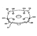
図2乃至図5は、回転入力部14の構造の例を示す。
【0019】
図2に示されるように、回転入力部14は、基本的に、ベース31、ホルダ32、スケール33、ダイヤル本体34、操作ダイヤル35、および中央ボタン部材36から構成される。
【0020】
ベース31は、例えば、絶縁性樹脂からなり、略矩形の板形状のものとして形成される。ベース31の上面の中央には中央ボタン41が設けられており、その周辺に、周辺ボタン42A乃至42Dがそれぞれ等間隔で配設されている。ベース31は、周辺ボタン42Aと周辺ボタン42Cを結ぶ線が、図1の携帯電話機1の上下方向の中心線とほぼ平行になるように配置される。従って、周辺ボタン42Aは、図1に示される携帯電話機1の上側に位置し、周辺ボタン42Bは、左側に位置する。また、周辺ボタン42Cは、図1に示される携帯電話機1の下側に位置し、周辺ボタン42Dは、右側に位置する(以下、適宜、周辺ボタン42Aを上ボタン42Aと、周辺ボタン42Bを左ボタン42Bと、周辺ボタン42Cを下ボタン42Cと、周辺ボタン42Dを右ボタン42Dと、それぞれ称する)。
【0021】
上動規制部材43には、ベース31の中央側に延びる爪が設けられており、その爪により、ホルダ32の上側への移動が規制される。上動規制部材43の両側には、やや離間して、回動規制部材44A、および44Bが設けられており、回動規制部材44A、および44Bにより、ホルダ32の回動が規制される。これらの上動規制部材43、回動規制部材44A、および44Bにより、ホルダ規制部51Aが構成され、同様のもの(ホルダ規制部51B,51C,51D)がベース31の4隅のうちの他の3隅にそれぞれ配置される。
【0022】
ホルダ32は、中央に孔を有する絶縁性ディスクの形状とされ、上面の中央部には、ダイヤル本体34等を回転自在に保持するダイヤル保持筒61が、孔の周辺から上面側(図2において上側)に突出した状態で形成されている。従って、ダイヤル保持筒61の孔の中心の軸が、ダイヤル本体34等の回転軸となる。
【0023】
また、ホルダ32の上面には、導電性を有する弾性材であるブラシ62A,62B、および62Cが配設されており、ブラシ62A,62B、および62Cと、ホルダ32の上に配置されるスケール33との電気的な接続の状態の変化を検出することで、回転入力部14(操作ダイヤル35)の回転量、および回転方向が検出される。
【0024】
具体的には、ブラシ62A、および62Bが配設される径方向の位置は、スケール33がホルダ32の上に配置されたとき、スケール33のスリット72と接触する位置とされ、回転入力部14が回転操作され、それに伴ってスケール33が回転されたとき、ブラシ62A、および62Bとスケール33との間では、接触(スリット72とスリット72の間の位置)、非接触(スリット72の位置)が繰り返されることとなる。
【0025】
一方、ブラシ(アースブラシ)62Cは、スケール33がホルダ32の上に配置されたとき、スケール33と常時接する位置に配設され、スケール33が回転されたとき、ブラシ62A、または62Bとの間で、スケール33を介して導通、または非導通を繰り返すこととなる。
【0026】
従って、ブラシ62A、または62Bと、ブラシ62Cの間の導通状態の変化(ブラシ62A、または62Bとスケール33の接触、非接触の繰り返し)に対応して発生されるパルスの数に基づいて、回転入力部14の回転量を算出することができる。
【0027】
また、ブラシ62Aとブラシ62Bを周方向に若干ずらして配設することにより、回転入力部14の回転方向を検出することができる。すなわち、図1の状態において回転入力部14が反時計方向に回転された場合、ブラシ62Aとスケール33が接触することにより発生されるパルスの立ち上がり(または立ち下がり)が、ブラシ62Bとスケール33が接触することにより発生されるパルスの立ち上がり(または立ち下がり)より、ずれている分だけ、早いタイミングで検出されることとなる。
【0028】
また、反対に、回転入力部14が時計方向に回転された場合、ブラシ62Bとスケール33が接触することにより発生されるパルスの立ち上がり(または立ち下がり)が、ブラシ62Aとスケール33が接触することにより発生されるパルスの立ち上がり(または立ち下がり)より、早いタイミングで検出されることとなる。
【0029】
従って、このように現れる、パルスの立ち上がり(または立ち下がり)のタイミングのずれに基づいて、回転入力部14の回転方向が検出される。
【0030】
ホルダ32の周縁部には、ホルダ規制部51A乃至51Dに対応して被規制部材63A乃至63Dが形成されており、ホルダ32がベース31上に配置されたとき、この被規制部材63A乃至63Dの変移(回転および離脱)が、ホルダ規制部51A乃至51Dによりそれぞれ規制される。
【0031】
なお、ホルダ32の裏面の、周辺ボタン42A乃至42Dに対応する位置には、図3に示されるように、ボタン押下用突起部101A乃至101Dが設けられている。従って、図1に示される携帯電話機1において、回転入力部14の上側が紙面と垂直な方向に押下されたとき、ボタン押下用突起部101Aにより上ボタン42A(周辺ボタン42A)が押下され、回転入力部14の左側が押下されたとき、ボタン押下用突起部101Bにより左ボタン42B(周辺ボタン42B)が押下される。同様に、回転入力部14の下側が押下されたとき、ボタン押下用突起部101Cにより下ボタン42C(周辺ボタン42C)が押下され、回転入力部14の右側が押下されたとき、ボタン押下用突起部101Dにより右ボタン42D(周辺ボタン42D)が押下される。
【0032】
ダイヤル本体保持部材64A乃至64Dは、ホルダ32の周縁部に、それぞれ所定の距離だけ離間し、上面側(図中上側)に突出した状態で形成されている。ダイヤル本体保持部材64A乃至64Dの上端部には、ホルダ32の中心側に延びる爪が形成されており、この爪により、ダイヤル本体34の離脱が制限されるようになされている。
【0033】
また、ホルダ32の上面には、クリック感用突起部65が設けられており、回転入力部14が回転されたとき、このクリック感用突起部65と、ダイヤル本体34のクリック感用凹凸部83により、ユーザに対するクリック感が発生される。
【0034】
スケール33の中央部には、ダイヤル保持筒61が挿嵌される孔71が形成され、その周辺部には、上述したように、スケール33の周縁部近傍に、所定の角度ピッチで放射状に多数のスリット72が形成されている。スケール33は、図4に示されるように、ダイヤル本体34の裏面に固定され、ホルダ32の上に配置される。
【0035】
ダイヤル本体34の中心には、ダイヤル保持筒61が挿嵌される孔81が形成され、また、ダイヤル本体34の上面には、伝動突起部82が形成されている。伝動突起部82は、操作ダイヤル35の裏面に形成される伝動凹部92に嵌合し、操作ダイヤル35の回転力をダイヤル本体34に伝動する。
【0036】
また、ダイヤル本体34の裏面の周縁部には、図4に示されるような波状のクリック感用凹凸部83が、その全周に渡って形成されており、上述したように、その凹部にクリック感用突起部65が遊嵌される。
【0037】
操作ダイヤル35の中央には、中央ボタン部材36が挿嵌される孔91が形成され、また、操作ダイヤル35の裏面には、ダイヤル本体34の伝動突起部82が嵌合される伝動凹部92が形成されている。中央ボタン部材36は、図2においては円筒状に図示されているが、球形でもよい。なお、操作ダイヤル35の上面には、回転操作時に適度な摩擦を生じて操作性を良くするため、放射状に延びる多数の溝93が形成されている。ただし、溝93は無くてもよい。
【0038】
以上のような各部材から、図5に示されるような回転入力部14が構成され、操作ダイヤル35の上面が露出した状態で携帯電話機1に組み込まれる。
【0039】
図5に示される回転入力部14において、ユーザは、操作ダイヤル35の右上方(図1では、上側)を押下することで、上ボタン42Aを押すことができる。また、操作ダイヤル35の左下方(図1では、下側)を押下することで、下ボタン42Cを押すことができる。さらに、操作ダイヤル35の左上方(図1では、左側)を押下することで、左ボタン42Bを押すことができ、操作ダイヤル35の右下方(図1では、右側)を押下することで、右ボタン42Dを押すことができる。
【0040】
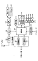
図6は、本発明を適用した携帯電話機1の内部の構成例を示すハードウェアブロック図である。
【0041】
制御部111は、メモリ117のROM(Read Only Memory)117Aに格納されている制御プログラムをRAM(Random Access Memory)117Bに展開し、展開した制御プログラムに従って、携帯電話機1の全体の動作を制御する。
【0042】
例えば、制御部111は、ユーザからの指示に基づいて、読出リスト情報を読み出すため等のプログラムを起動し、表示部13の表示範囲を変更する。そして、入力検出部115の回転検出部121により、回転入力部14に対する入力が検出されたとき(回転入力部14が回転されたとき)、制御部111は、DSP(Digital Signal Processor)を制御して、回転入力部14の回転量や回転方向等を算出し、表示部13の表示内容を変更する。回転入力部14に対する入力に応じて、表示部13の表示内容を変更する制御部111の処理については後に詳述する。
【0043】
RF(Radio Frequency)部112は、アンテナ11を介して、基地局との間で電波を送受信し、例えば、音声通話モード時において、アンテナ11で受信されたRF信号を増幅して周波数変換処理およびアナログディジタル変換処理等の所定の処理を施し、得られた音声データをDSP113に出力する。また、RF部112は、DSP113から音声データが供給されてきたとき、ディジタルアナログ変換処理、および周波数変換処理等の所定の処理を施し、得られた音声信号をアンテナ11から送信する。
【0044】
DSP113は、RF部112から供給されてきた音声データに対して、例えば、スペクトラム逆拡散処理を施し、得られたデータを音声コーデック114に出力する。また、DSP113は、音声コーデック114から供給されてきた音声データに対してスペクトラム拡散処理を施し、得られたデータをRF部112に出力する。また、DSP113は、制御部111による制御に基づいて、画像の表示を切り替えるための回転量の算出、回転方向の算出等の処理を行う。
【0045】
音声コーデック114は、マイクロフォン18により集音されたユーザの音声を音声データに変換し、それをDSP113に出力する。また、音声コーデック114は、DSP113から供給されてきた音声データをアナログ音声信号に変換し、対応する音声信号をスピーカ12から出力する。
【0046】
入力検出部115の回転検出部121には、図2のブラシ62A,62B、および62Cが接続されており、回転検出部121は、ブラシ62A、および62Bとスケール33との接触、非接触の状態を監視し、接触状態の変化に対応するパルスを制御部111に出力する。
【0047】
入力検出部115の押下検出部122には、図2の中央ボタン41、および周辺スイッチ42A乃至42Dが接続されており、押下検出部122は、これらのボタンが押下されたとき(回転入力部14の上面が内部方向に押下されたとき)、それを検出し、対応する信号を制御部111に出力する。
【0048】
制御部111には、必要に応じてドライブ210が接続され、磁気ディスク211、光ディスク212、光磁気ディスク213、或いは半導体メモリ214などが適宜装着され、それから読み出されたコンピュータプログラム(例えば、リスト読出部111a、カーソル位置決定部111b、グループ選択部14a等を実現するためのプログラム)が、必要に応じて制御部111にインストールされる。
【0049】
入力検出部116は、携帯電話機1に設けられている通話ボタン15、電源ボタン16、およびテンキー17等の他のボタンからの入力を検出し、対応する信号を制御部111に出力する。
【0050】
図7は、本発明の実施形態にかかる携帯電話機(携帯情報通信端末)1の機能ブロック図である。携帯電話機(携帯情報通信端末)1は、表示部13、グループ選択部14a、第一スクロール部(識別可能項目変更手段)14b、第二スクロール部(特定項目変更手段)14c、リスト情報読出部111a、カーソル位置決定部111b、メモリ117を備える。
【0051】
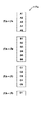
メモリ117は、リスト情報117aを記録する。リスト情報117aの一例を図8に示す。リスト情報117aは、個々の項目A1、A2、…、A5、B1、B2、…、B6、C1、C2、…、C5、D1、…を有する。個々の項目はグループに対応付けられている。例えば、項目A1、A2、…、A5はグループAに、項目B1、B2、…、B6はグループBに、項目C1、C2、…、C5はグループCに、項目D1、…はグループDに対応付けられている。しかも、個々の項目A1、A2、…は順番が付けられている。例えば、項目A1の次は項目A2、項目A2の次は、…、項目A5の次は項目B1、項目B1の次は項目B2、…、項目B6の次は項目C1、項目C1の次は項目C2、…、項目C5の次は項目D1、…となっている。なお、各グループの境界にはスペースが配置されているものとする。
【0052】
グループ選択部14aは、グループを選択する。グループ選択部14aは、ホルダ32、ダイヤル本体34、操作ダイヤル35、左ボタン42B、右ボタン42Dを有する。グループ選択部14aの操作ダイヤル35の左方を押し下げると左ボタン42Bを押すことになる。また、グループ選択部14aの操作ダイヤル35の右方を押し下げると、右ボタン42Dを押すことになる。左ボタン42Bを押すことは一つ前のグループを選択することに対応し、右ボタン42Dを押すことは一つ後のグループを選択することに対応する。ただし、グループはABCDEの順番であるものとする。例えば、グループCが選択されている場合に、左ボタン42Bを押せばグループBが、右ボタン42Dを押せばグループDが選択される。
【0053】
リスト情報読出部111aは、選択されたグループに対応し、選択されたグループにおける所定の順番にある特定項目から所定範囲内のリスト情報を読み出す。リスト情報の読み出しを図9を参照して説明する。
【0054】
図9はグループCが選択された場合のリスト情報の読み出し例を示している。グループCに対応する項目はC1、C2、…、C5である。ここで、所定の順番はグループ内の先頭であるとする。よって、特定項目117bはC1となる。また、所定範囲の始まりは特定項目から3番前(項目B5)であり、終わりは特定項目から4番後(項目C5)とする。よって、読み出された読出リスト情報117cは項目B5〜項目C5である。
【0055】
表示部13は、グループ表示部13a、リスト表示部13b、カーソル表示部(特定項目表示手段)13cを有する。表示部13の表示内容を図10を参照して説明する。
【0056】
グループ表示部13aは、選択されたグループを表示する。図10に示す例ではグループCが選択されている。なお、グループ表示部13aは横長にグループ名を表示する。このため、左ボタン42B(右ボタン42D)を押すことが一つ前(後)のグループを選択することに対応することがわかりやすい。
【0057】
リスト表示部13bは、リスト情報読出部111aが読み出した読出リスト情報117cを表示する。
【0058】
カーソル表示部(特定項目表示手段)13cは、特定項目(項目C1)にカーソルをあわせて、他の項目と識別可能にして表示する。
【0059】
カーソル位置決定部111bは、カーソル表示部13cが表示するカーソルの位置を決定する。図10の例でいえば、最上行から4行目をカーソルの位置とする。リスト情報読出部111aは、特定項目から3番前からリスト情報を読み出すため、カーソルは特定項目(項目C1)に重なることになる。
【0060】
第一スクロール部(識別可能項目変更手段)14bは、ホルダ32、ダイヤル本体34、操作ダイヤル35、上ボタン42A、下ボタン42Cを有する。グループ選択部14aの操作ダイヤル35の上方を押し下げると上ボタン42Aを押すことになる。また、グループ選択部14aの操作ダイヤル35の下方を押し下げると、下ボタン42Cを押すことになる。上ボタン42A(下ボタン42C)を押すことは、カーソルにより識別可能に表示される項目を一つ前(後)の順番の項目に変更することに対応する。すなわち、カーソル位置決定部111bに、カーソルの位置を1行上(下)に移動させることを指示する。これにより、カーソル表示部13cが表示するカーソルの位置が変更される。
【0061】
なお、カーソルにより識別可能に表示される項目がリスト表示部13bの上端(下端)に位置した場合は、カーソルにより識別可能に表示される項目が上端(下端)に位置し続けるように読出リスト情報117cを読み出す。
【0062】
また、グループ表示部13aは、カーソルにより識別可能に表示される項目が対応するグループを表示する。このグループは、リスト情報読出部111aから取得できる。
【0063】
第一スクロール部14bの動作による表示部13の表示内容の変化を図11を参照して説明する。まず、表示部13の表示内容が図11(a)に示すようなものであるとする。ここで、下ボタン42Cを押すと、カーソル位置決定部111bに、カーソルの位置を1行下に移動させることを指示する。これにより、カーソル表示部13cが表示するカーソルの位置が1行下にされる(図11(b)参照)。下ボタン42Cを押すことを繰り返せば、カーソル表示部13cが表示するカーソルの位置がリスト表示部13bの最終行になる(図11(c)参照)。ここまで、リスト表示部13bが表示する項目は一定であり(項目B5〜項目C5)、表示位置も一定である。
【0064】
図11(c)の状態で、さらに下ボタン42Cを押すと、項目C5の次の順番の項目D1をカーソルにより識別可能に表示することになる。しかし、項目D1が読出リスト117cには含まれていないので、項目D1をリスト表示部13bの下端(8行目)に含むように、リスト情報読出部111aが読出リスト117cを読み出す。すなわち、リスト情報読出部111aは、第一スクロール部14bから項目D1を受け、カーソル位置決定部111bからカーソルが下端(8行目)にあることを受ける。そして、項目D1が最終の順番になるように、項目D1から7番前(項目B6)までをリスト情報読出部111aが読み出す。そして、リスト情報読出部111aが読み出した読出リスト情報117cを表示する(図11(d)参照)。ここで、カーソルにより他の項目と識別可能に表示された項目に対応するグループがCからDに変化したので、グループ表示部13aもDグループを表示する。
【0065】
第二スクロール部(特定項目変更手段)14cは、スケール33、ダイヤル本体34、操作ダイヤル35、ブラシ62A、62B、62Cを有する。操作ダイヤル35を中央ボタン部材36を回転軸として回転させる。回転量および回転方向は先に説明したように、スケール33とブラシ62A、62B、62Cとの接触に基づき検出される。時計(反時計)回りに所定量(例えば30度)回転させることが、特定項目を一つ後(前)の順番の項目に変更することに対応する。
【0066】
なお、グループ表示部13aは、カーソルにより識別可能に表示される特定項目が対応するグループを表示する。このグループは、リスト情報読出部111aから取得できる。
【0067】
また、第一スクロール部14bと第二スクロール部14cとは操作ダイヤル35を共有しており、操作ダイヤル35への操作によりいずれが作動するかが決定される。操作ダイヤル35の上(下)方を押せば第一スクロール部14bが、操作ダイヤル35を回転すれば第二スクロール部14cが作動する。
【0068】
第二スクロール部14cの動作による表示部13の表示内容の変化を図12を参照して説明する。まず、表示部13の表示内容が図12(a)に示すようなものであるとする。ここで、操作ダイヤル35を反時計回りに30度回転させると、特定項目が項目C1から一つ前の項目B6に変更される。これにより、リスト情報読出部111aは、特定項目から3番前(項目B3)〜特定項目から4番後(項目C3)の読出リスト117cを読み出す。また、カーソルは特定項目B6に重なる(図12(b)参照)。ここで、リスト表示部13bに表示される項目は変更されるものの、特定項目の表示位置は上から4行目のままである。すなわち、リスト表示部13bは特定項目の表示位置を一定に保つ。ここで、カーソルにより他の項目と識別可能に表示された特定項目に対応するグループがCからBに変化したので、グループ表示部13aもBグループを表示する。
【0069】
次に、本発明の実施形態の動作を説明する。
【0070】
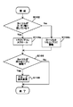
図13は、本発明の実施形態にかかる携帯電話機1の動作を示すフローチャートである。
【0071】
まず、入力検出部115が回転入力部14に入力があるか否かを判定する(S10)。回転入力部14に入力があれば(S10、Yes)、回転検出部121および押下検出部122により、入力が操作ダイヤル35の回転か、上(下)ボタン42A(C)の押下か、左(右)ボタン42B(D)の押下かが判定される(S12)。
【0072】
左(右)ボタン42B(D)の押下であれば(S12、左右)、グループ表示処理(S14)、上(下)ボタン42A(C)の押下であれば(S14、上下)、第一スクロール処理(S16)、回転であれば(S14、回転)、第二スクロール処理(S18)を行う。そして、回転入力部14への入力の有無の判定(S10)に戻る。
【0073】
なお、回転入力部14に入力がなければ(S10、No)、処理を終了する。
【0074】
図14は、グループ表示処理(S14)の処理の詳細を示すフローチャートである。まず、グループ選択部14aの左(右)ボタン42B(D)の押下によりグループが選択される(S142)。選択されたグループは、グループ選択部14aからグループ表示部13aに送られて表示される。そして、選択されたグループの先頭の項目がリスト表示部13bに表示されているか否かを、リスト情報読出部111aが判定する(S144)。
【0075】
選択されたグループの先頭の項目がリスト表示部13bに表示されているならば(S144、Yes)、リスト情報読出部111aは、選択されたグループの先頭の項目の位置をカーソル位置決定部111bに送る。カーソル位置決定部111bはこの位置をカーソルの位置とし、カーソル表示部13cがカーソルを選択されたグループの先頭の項目の位置に移動する(S146)。そして、処理を終了する。
【0076】
選択されたグループの先頭の項目(特定項目)がリスト表示部13bに表示されていないならば(S144、No)、リスト情報読出部111aは、特定項目に基づき読出リスト情報117cを読み出す(S148)。そして、リスト表示部13bは読出リスト情報117cを表示する。最後に、カーソル表示部13cが、特定項目にカーソルを移動させて(S149)、他の項目と識別可能にして表示する。そして、処理を終了する。
【0077】
図15は、第一スクロール処理(S16)の詳細を示すフローチャートである。まず、グループ選択部14aの上(下)ボタン42A(C)が押下される。すると、カーソルがリスト表示部13bの上(下)端に達しているか否かをリスト情報読出部111aが判定する(S162)。カーソルがリスト表示部13bの上(下)端に達しているならば(S162、Yes)(図11(c)参照)、カーソルにより識別可能に表示される項目が上端(下端)に位置し続けるようにリスト情報読出部111aが読出リスト情報117cを読み出す。これにより、表示される項目が1行上(下)にスクロールされることになる(S164a:図11(d)参照)。カーソルがリスト表示部13bの上(下)端に達していないならば(S162、No)(図11(a)参照)、カーソル位置決定部111bによりカーソルの位置を1行上(下)に移動させる(S164b:図11(b)参照)。
【0078】
S164a、bの処理後、リスト情報読出部111aはカーソルが別グループに移動したか否かを判定する(S166)。移動していないならば(S166、No)、処理を終了する。移動しているならば(S166、Yes)、リスト情報読出部111aは、カーソルの位置するグループをグループ表示部13aに送り、グループ表示を変更する(S168:図11(d)参照)。そして、処理を終了する。
【0079】
図16は、第二スクロール処理(S18)の詳細を示すフローチャートである。まず、グループ選択部14aの操作ダイヤル35が時計(反時計)回りに所定回転量(例、30度)回転される。これにより、特定項目が一つ後(前)の順番の項目に変更される。よって、リスト情報読出部111aが読み出す読出リスト情報117cも一つ後(前)にずれるので、リスト表示部13bにより表示される項目が1行上(下)にスクロールされることになる(S184:図12(b)参照)。
【0080】
表示される項目のスクロール(S184)の後、リスト情報読出部111aはカーソルが別グループに移動したか否かを判定する(S186)。移動していないならば(S186、No)、処理を終了する。移動しているならば(S186、Yes)、リスト情報読出部111aは、カーソルの位置するグループをグループ表示部13aに送り、グループ表示を変更する(S188:図12(b)参照)。そして、処理を終了する。
【0081】
本発明の実施形態によれば、リスト情報読出部111aが、選択されたグループにおける所定の順番(先頭)にある特定項目から所定範囲内(3番前〜4番後)の読出リスト情報117cを読み出す。これにより、所望のグループに表示範囲を変更することができ、長大なリスト情報117aを閲覧する際に便利である。
【0082】
しかも、特定項目から所定範囲内のリスト情報は、別々のグループに対応する項目が含まれていることが一般的である。例えば、グループCの先頭項目が特定項目ならば、グループBに対応する項目がリスト情報に含まれている。よって、別々のグループ(グループB、C)に対応する項目を同時に表示できる。
【0083】
さらに、グループを超えたスクロール(第一スクロール、第二スクロール)も可能なので、全項目を一覧することができ、全項目の個数も容易に把握できる。
【0084】
また、スクロールの形態(第一スクロール、第二スクロール)を、第一スクロール部14bと第二スクロール部14cとが共有する部材である操作ダイヤル35への操作により切り替えられるので便利である。例えば、表示させたい項目を第二スクロールにより表示させ、その後、第一スクロールによりカーソルをその項目に移動させるようにできる。
【0085】
なお、本発明の実施形態においては、入力デバイスとして回転入力部14を使用するようになっている。しかし、入力デバイスとしては周知のジョグダイヤルを用いてもよい。図17は、ジョグダイヤルを備えた携帯電話機1の斜視図である。
【0086】
携帯電話機1は、表示部13、ジョグダイヤル3、左キー4a、右キー4bを備える。
【0087】
ジョグダイヤル3は、回転および押下可能な操作素子である。図18は、ジョグダイヤル3の平面図および側面図である。ジョグダイヤル3は、(1)上に回転させる、(2)下に回転させる、(3)背後に向かって押す、の三種類の動作が可能である。
【0088】
ジョグダイヤル3を上下に回転させた場合の動作は、操作ダイヤル35の回転の際の動作と同様である。左キー4aおよび右キー4bを押したときの動作は、左(右)ボタン42B(D)の押下の際の動作と同様である。
【0089】
また、上記の実施形態は、以下のようにして実現できる。CPU、ハードディスク、フラッシュメモリ、メディア(フロッピーディスク、CD−ROM、メモリスティックなど)読み取り装置を備えたコンピュータのメディア読み取り装置に、上記の各部分(例えば、リスト情報読出部111a、カーソル位置決定部111b)を実現するプログラムを記録したメディアを読み取らせて、ハードディスク、フラッシュメモリなどにインストールする。このような方法でも、上記の機能を実現できる。
【0090】
【発明の効果】
本発明によれば、リスト情報読出手段が、選択されたグループにおける所定の順番にある特定項目から所定範囲内のリスト情報を読出リスト情報として読み出す。特定項目から所定範囲内のリスト情報は、別々のグループに対応する項目が含まれていることが一般的である。よって、別々のグループに対応する項目を同時に表示できる。
【図面の簡単な説明】
【図1】本発明を適用した携帯電話機1の外観の構成例を示す図である。
【図2】回転入力部14の分解斜視図である。
【図3】ホルダ32の裏面を示す斜視図である。
【図4】スケール33がダイヤル本体34に固定された状態を示す斜視図である。
【図5】回転入力部14の斜視図である。
【図6】本発明を適用した携帯電話機1の内部の構成例を示すハードウェアブロック図である。
【図7】本発明の実施形態にかかる携帯電話機(携帯情報通信端末)1の機能ブロック図である。
【図8】リスト情報117aの一例を示す図である。
【図9】リスト情報の読み出しを説明する図である。
【図10】表示部13の表示内容を説明する図である。
【図11】第一スクロール部14bの動作による表示部13の表示内容の変化を示す図である。
【図12】第二スクロール部14cの動作による表示部13の表示内容の変化を示す図である。
【図13】本発明の実施形態にかかる携帯電話機1の動作を示すフローチャートである。
【図14】グループ表示処理(S14)の処理の詳細を示すフローチャートである。
【図15】第一スクロール処理(S16)の詳細を示すフローチャートである。
【図16】第二スクロール処理(S18)の詳細を示すフローチャートである。
【図17】ジョグダイヤルを備えた携帯電話機1の斜視図である。
【図18】ジョグダイヤル3の平面図および側面図である。
【図19】従来技術におけるメニュー構造を採用した場合の情報の表示態様を示す図である。
【符号の説明】
1 携帯電話機(携帯情報通信端末)
13 表示部
13a グループ表示部
13b リスト表示部
13c カーソル表示部(特定項目表示手段)
14a グループ選択部
14b 第一スクロール部(識別可能項目変更手段)
14c 第二スクロール部(特定項目変更手段)
35 操作ダイヤル(共有部材)
111a リスト情報読出部
111b カーソル位置決定部
117 メモリ[0001]
TECHNICAL FIELD OF THE INVENTION
The present invention relates to display of a screen on a portable information communication terminal such as a mobile phone.
[0002]
[Prior art]
2. Description of the Related Art Conventionally, a portable information communication terminal such as a mobile phone displays information or the like obtained via the Internet on a screen. At this time, if the information amount is large and the information is displayed as it is, only a part of the information to be displayed may be displayed on the screen. Therefore, a menu structure is adopted so that information to be displayed can be displayed.
[0003]
A display mode of information when a menu structure according to the related art is adopted will be described with reference to FIG. First, a
[0004]
While there are ten pieces of information A1, A2, A3, B1, B2, B3, C1, C2, C3, and C4, only about four lines of information can be displayed on the
[0005]
[Problems to be solved by the invention]
However, when the menu structure is adopted, it is difficult to understand how many pieces of information are present. Selecting a menu item to display information and calculating the sum of the information (eg, 3 + 3 + 4 = 10) can be understood but takes time.
[0006]
Furthermore, information corresponding to different menu items cannot be displayed simultaneously. For example, information A3 and information B1 cannot be displayed simultaneously.
[0007]
As described above, when the menu structure is adopted, there is an inconvenience that information is separately displayed for each menu item.
[0008]
Therefore, an object of the present invention is to solve the inconvenience caused by displaying information separately for each menu item when a menu structure is adopted.
[0009]
[Means for Solving the Problems]
The present invention relates to a portable information communication terminal. A portable information communication terminal according to the present invention includes a list information recording unit, a group selection unit, and a list information reading unit.
[0010]
The list information recording means records list information in which individual items are associated with groups and the individual items are ordered. The group selection means selects a group. The list information reading means reads, as read list information, list information corresponding to the selected group and within a predetermined range from specific items in a predetermined order in the selected group.
[0011]
According to the invention configured as described above, the list information reading means reads list information within a predetermined range from specific items in a predetermined order in the selected group as read list information. The list information within a predetermined range from a specific item generally includes items corresponding to different groups. Therefore, items corresponding to different groups can be displayed simultaneously.
[0012]
BEST MODE FOR CARRYING OUT THE INVENTION
Hereinafter, embodiments of the present invention will be described with reference to the drawings.
[0013]
FIG. 1 is a diagram showing a configuration example of the appearance of a
[0014]
At substantially the center of the
[0015]
In the
[0016]
A speaker 12 and a
[0017]
In addition to the so-called straight type shown in FIG. 1, the
[0018]
2 to 5 show examples of the structure of the
[0019]
As shown in FIG. 2, the
[0020]
The
[0021]
The upward
[0022]
The
[0023]
On the upper surface of the
[0024]
Specifically, the radial position where the
[0025]
On the other hand, the brush (earth brush) 62C is arranged at a position where it is always in contact with the
[0026]
Therefore, rotation is performed based on the number of pulses generated in response to a change in the conduction state between the
[0027]
In addition, by arranging the
[0028]
Conversely, when the
[0029]
Therefore, the rotation direction of the
[0030]
[0031]
As shown in FIG. 3,
[0032]
The dial main
[0033]
A
[0034]
A
[0035]
A
[0036]
Further, a wavy click feeling
[0037]
A
[0038]
The
[0039]
In the
[0040]
FIG. 6 is a hardware block diagram showing an example of the internal configuration of the
[0041]
The
[0042]
For example, the
[0043]
An RF (Radio Frequency)
[0044]
The
[0045]
The
[0046]
The
[0047]
The center button 41 of FIG. 2 and the
[0048]
A drive 210 is connected to the
[0049]
Input detection section 116 detects an input from other buttons such as
[0050]
FIG. 7 is a functional block diagram of the mobile phone (portable information communication terminal) 1 according to the embodiment of the present invention. The mobile phone (portable information communication terminal) 1 includes a
[0051]
The
[0052]
The group selector 14a selects a group. The group selector 14a has a
[0053]
The list
[0054]
FIG. 9 shows an example of reading out the list information when the group C is selected. Items corresponding to the group C are C1, C2,..., C5. Here, it is assumed that the predetermined order is the head in the group. Therefore, the
[0055]
The
[0056]
The
[0057]
The
[0058]
The cursor display unit (specific item display means) 13c positions the cursor on the specific item (item C1) and displays the specific item so that it can be distinguished from other items.
[0059]
The cursor
[0060]
The first scroll section (identifiable item changing means) 14b has a
[0061]
When the item displayed identifiable by the cursor is located at the upper end (lower end) of the
[0062]
Further, the
[0063]
A change in the display content of the
[0064]
When the lower button 42C is further pressed in the state of FIG. 11C, the item D1 in the next order from the item C5 is displayed so as to be identifiable by the cursor. However, since the item D1 is not included in the
[0065]
The second scroll section (specific item changing means) 14c has a
[0066]
In addition, the
[0067]
Further, the
[0068]
A change in the display content of the
[0069]
Next, the operation of the embodiment of the present invention will be described.
[0070]
FIG. 13 is a flowchart illustrating an operation of the
[0071]
First, the input detection unit 115 determines whether there is an input to the rotation input unit 14 (S10). If there is an input to the rotation input unit 14 (S10, Yes), the
[0072]
If the left (right) button 42B (D) is pressed (S12, left and right), the group display processing (S14), if the up (down)
[0073]
If there is no input in the rotation input unit 14 (S10, No), the process ends.
[0074]
FIG. 14 is a flowchart showing details of the group display processing (S14). First, a group is selected by pressing the left (right) button 42B (D) of the group selection unit 14a (S142). The selected group is sent from the group selection unit 14a to the
[0075]
If the first item of the selected group is displayed on the
[0076]
If the first item (specific item) of the selected group is not displayed on the
[0077]
FIG. 15 is a flowchart showing details of the first scroll processing (S16). First, the upper (lower)
[0078]
After the processing of S164a, b, the list
[0079]
FIG. 16 is a flowchart showing details of the second scroll processing (S18). First, the
[0080]
After scrolling the displayed items (S184), the list
[0081]
According to the embodiment of the present invention, the list
[0082]
In addition, the list information within a predetermined range from the specific item generally includes items corresponding to different groups. For example, if the first item of the group C is a specific item, the item corresponding to the group B is included in the list information. Therefore, items corresponding to different groups (groups B and C) can be displayed simultaneously.
[0083]
Further, scrolling beyond the group (first scroll, second scroll) is also possible, so that all items can be listed and the number of all items can be easily grasped.
[0084]
Further, the scroll mode (first scroll, second scroll) can be conveniently switched by operating the
[0085]
In the embodiment of the present invention, the
[0086]
The
[0087]
The
[0088]
The operation when the
[0089]
Further, the above embodiment can be realized as follows. The above parts (for example, the list
[0090]
【The invention's effect】
According to the present invention, the list information reading means reads list information within a predetermined range from a specific item in a predetermined order in the selected group as read list information. The list information within a predetermined range from a specific item generally includes items corresponding to different groups. Therefore, items corresponding to different groups can be displayed simultaneously.
[Brief description of the drawings]
FIG. 1 is a diagram showing a configuration example of an appearance of a
FIG. 2 is an exploded perspective view of the
FIG. 3 is a perspective view showing a back surface of the
FIG. 4 is a perspective view showing a state in which the
FIG. 5 is a perspective view of the
FIG. 6 is a hardware block diagram showing an example of the internal configuration of the
FIG. 7 is a functional block diagram of a mobile phone (portable information communication terminal) 1 according to the embodiment of the present invention.
FIG. 8 is a diagram showing an example of
FIG. 9 is a diagram illustrating reading of list information.
FIG. 10 is a diagram for explaining display contents of a
FIG. 11 is a diagram showing a change in display content of a
FIG. 12 is a diagram illustrating a change in display content of a
FIG. 13 is a flowchart showing an operation of the
FIG. 14 is a flowchart illustrating details of a group display process (S14).
FIG. 15 is a flowchart illustrating details of a first scroll process (S16).
FIG. 16 is a flowchart showing details of a second scroll process (S18).
FIG. 17 is a perspective view of a
18 is a plan view and a side view of the
FIG. 19 is a diagram showing a display mode of information when a menu structure according to a conventional technique is adopted.
[Explanation of symbols]
1 mobile phone (portable information communication terminal)
13 Display
13a Group display section
13b List display section
13c cursor display section (specific item display means)
14a Group selection section
14b 1st scroll part (identifiable item changing means)
14c Second scroll part (specific item changing means)
35 Operation dial (shared member)
111a List information reading unit
111b Cursor position determination unit
117 memory
Claims (12)
前記グループを選択するグループ選択手段と、
選択されたグループに対応し、前記選択されたグループにおける所定の順番にある特定項目から所定範囲内のリスト情報を読出リスト情報として読み出すリスト情報読出手段と、
を備えた携帯情報通信端末。List information recording means for recording list information in which individual items are associated with a group and the individual items are ordered,
Group selection means for selecting the group,
List information reading means corresponding to the selected group and reading list information within a predetermined range from specific items in a predetermined order in the selected group as read list information;
Mobile information communication terminal equipped with.
前記リスト情報読出手段が読み出した読出リスト情報を表示するリスト表示手段と、
前記選択されたグループを表示するグループ表示手段と、
を備えた携帯情報通信端末。The mobile information communication terminal according to claim 1,
List display means for displaying the read list information read by the list information read means,
Group display means for displaying the selected group;
Mobile information communication terminal equipped with.
前記特定項目を他の項目と識別可能に表示する特定項目表示手段、
を備えた携帯情報通信端末。The mobile information communication terminal according to claim 2,
Specific item display means for displaying the specific item so as to be distinguishable from other items,
Mobile information communication terminal equipped with.
前記所定の順番はグループ内の先頭である携帯情報通信端末。The portable information communication terminal according to claim 1, wherein:
The mobile information communication terminal, wherein the predetermined order is a head of the group.
識別可能に表示される項目を変更する識別可能項目変更手段を備え、
前記リスト表示手段は表示する項目の位置を一定に保つ、
携帯情報通信端末。The portable information communication terminal according to claim 3 or 4,
An identifiable item changing means for changing an item displayed to be identifiable,
The list display means keeps the position of the item to be displayed constant,
Mobile information communication terminal.
前記識別可能に表示される項目が前記リスト表示手段の端部に位置する場合に、前記識別可能項目変更手段により識別可能に表示される項目が前記リスト表示手段の端部に位置し続けるように前記リスト情報読出手段が前記リスト情報を読み出す携帯情報通信端末。The portable information communication terminal according to claim 5, wherein
In the case where the item displayed identifiably is located at the end of the list display means, the item displayed identifiable by the identifiable item changing means is kept at the end of the list display means. A portable information communication terminal, wherein the list information reading means reads the list information.
前記特定項目を変更する特定項目変更手段を備え、
前記リスト表示手段は前記特定項目の表示位置を一定に保つ、
携帯情報通信端末。The portable information communication terminal according to claim 3 or 4,
Comprising a specific item changing means for changing the specific item,
The list display means keeps the display position of the specific item constant;
Mobile information communication terminal.
前記グループ表示手段は前記識別可能に表示される項目に対応するグループを表示する、
携帯情報通信端末。The portable information communication terminal according to claim 5 or 6,
The group display means displays a group corresponding to the item that is identifiably displayed,
Mobile information communication terminal.
前記グループ表示手段は前記特定項目に対応するグループを表示する、
携帯情報通信端末。The mobile information communication terminal according to claim 7,
The group display means displays a group corresponding to the specific item,
Mobile information communication terminal.
識別可能に表示される項目を変更する識別可能項目変更手段と、
前記特定項目を変更する特定項目変更手段と
を備え、
前記識別可能項目変更手段と前記特定項目変更手段とは共有部材を共有し、
前記共有部材に対する操作により、前記識別可能項目変更手段または前記特定項目変更手段のいずれを作動させるかが決定される、
携帯情報通信端末。The portable information communication terminal according to claim 3 or 4,
An identifiable item changing means for changing an item displayed to be identifiable;
A specific item changing means for changing the specific item,
The identifiable item changing means and the specific item changing means share a common member,
By operating the shared member, it is determined which of the identifiable item changing unit and the specific item changing unit is to be operated,
Mobile information communication terminal.
前記グループを選択するグループ選択処理と、
選択されたグループに対応し、前記選択されたグループにおける所定の順番にある特定項目から所定範囲内のリスト情報を読出リスト情報として読み出すリスト情報読出処理と、
をコンピュータに実行させるためのプログラム。List information recording processing for recording list information in which individual items are associated with groups and the individual items are ordered;
A group selection process for selecting the group;
List information reading processing for reading list information within a predetermined range from a specific item in a predetermined order in the selected group corresponding to the selected group as read list information;
A program for causing a computer to execute.
前記グループを選択するグループ選択処理と、
選択されたグループに対応し、前記選択されたグループにおける所定の順番にある特定項目から所定範囲内のリスト情報を読出リスト情報として読み出すリスト情報読出処理と、
をコンピュータに実行させるためのプログラムを記録したコンピュータによって読み取り可能な記録媒体。List information recording processing for recording list information in which individual items are associated with groups and the individual items are ordered;
A group selection process for selecting the group;
List information reading processing for reading list information within a predetermined range from a specific item in a predetermined order in the selected group corresponding to the selected group as read list information;
And a computer-readable recording medium recording a program for causing a computer to execute the program.
Priority Applications (6)
| Application Number | Priority Date | Filing Date | Title |
|---|---|---|---|
| JP2002179563A JP2004021893A (en) | 2002-06-20 | 2002-06-20 | Portable information communication terminal, program and recording medium recording program |
| EP03760930A EP1515221A4 (en) | 2002-06-20 | 2003-06-20 | Mobile information communication terminal, program, and recording medium containing the program |
| US10/487,161 US8694917B2 (en) | 2002-06-20 | 2003-06-20 | Mobile information communication terminal program and recording medium containing the program |
| KR1020047002423A KR101073714B1 (en) | 2002-06-20 | 2003-06-20 | Mobile information communication terminal program and recording medium containing the program |
| PCT/JP2003/007889 WO2004001571A1 (en) | 2002-06-20 | 2003-06-20 | Mobile information communication terminal, program, and recording medium containing the program |
| CNB038010488A CN1266574C (en) | 2002-06-20 | 2003-06-20 | Mobile information communication terminal, program, and recording medium containing the program |
Applications Claiming Priority (1)
| Application Number | Priority Date | Filing Date | Title |
|---|---|---|---|
| JP2002179563A JP2004021893A (en) | 2002-06-20 | 2002-06-20 | Portable information communication terminal, program and recording medium recording program |
Publications (2)
| Publication Number | Publication Date |
|---|---|
| JP2004021893A true JP2004021893A (en) | 2004-01-22 |
| JP2004021893A5 JP2004021893A5 (en) | 2005-07-21 |
Family
ID=29996571
Family Applications (1)
| Application Number | Title | Priority Date | Filing Date |
|---|---|---|---|
| JP2002179563A Pending JP2004021893A (en) | 2002-06-20 | 2002-06-20 | Portable information communication terminal, program and recording medium recording program |
Country Status (6)
| Country | Link |
|---|---|
| US (1) | US8694917B2 (en) |
| EP (1) | EP1515221A4 (en) |
| JP (1) | JP2004021893A (en) |
| KR (1) | KR101073714B1 (en) |
| CN (1) | CN1266574C (en) |
| WO (1) | WO2004001571A1 (en) |
Cited By (9)
| Publication number | Priority date | Publication date | Assignee | Title |
|---|---|---|---|---|
| JP2006033776A (en) * | 2004-07-22 | 2006-02-02 | Sony Corp | Electronic apparatus, display control method of electronic apparatus, and graphical user interface |
| JP2006323820A (en) * | 2005-05-16 | 2006-11-30 | Lg Electronics Inc | Mobile terminal with scrolling wheel device and function executing method using it |
| JP2007523421A (en) * | 2004-02-19 | 2007-08-16 | クゥアルコム・ケンブリッジ・リミテッド | Displaying menu items in the user interface |
| JP2007536604A (en) * | 2004-05-10 | 2007-12-13 | 松下電器産業株式会社 | User interface device, program, and recording medium |
| US7703043B2 (en) | 2004-07-12 | 2010-04-20 | Sony Corporation | Electronic apparatus, display controlling method for electronic apparatus and graphical user interface |
| JP2011107736A (en) * | 2009-09-29 | 2011-06-02 | Jvc Kenwood Holdings Inc | Multimedia device and screen display method |
| JP2012053561A (en) * | 2010-08-31 | 2012-03-15 | Honda Motor Co Ltd | Rotary input device |
| JP2016038672A (en) * | 2014-08-06 | 2016-03-22 | 角田 達雄 | Character string selection input apparatus and character string selection input program |
| WO2018147160A1 (en) * | 2017-02-13 | 2018-08-16 | パイオニア株式会社 | Display control device, display control method, and program for display control device |
Families Citing this family (29)
| Publication number | Priority date | Publication date | Assignee | Title |
|---|---|---|---|---|
| KR100594050B1 (en) * | 2005-05-17 | 2006-06-30 | 삼성전자주식회사 | Method for displaying menu screen in mobile communication terminal |
| US7404152B2 (en) | 2005-06-03 | 2008-07-22 | Research In Motion Limited | Displaying messages on handheld devices |
| ATE415653T1 (en) * | 2005-06-03 | 2008-12-15 | Research In Motion Ltd | NEWS DISPLAY ON PORTABLE DEVICES |
| JP4276640B2 (en) * | 2005-06-17 | 2009-06-10 | 株式会社ソニー・コンピュータエンタテインメント | Information processing apparatus, information processing apparatus control method, and information processing program |
| KR101078158B1 (en) * | 2006-01-13 | 2011-10-28 | 엘지전자 주식회사 | Jog dial and mobile terminal having the same |
| US9880702B2 (en) * | 2006-02-03 | 2018-01-30 | Yahoo Holdings, Inc. | Content structures and content navigation interfaces |
| US20070233714A1 (en) * | 2006-04-03 | 2007-10-04 | Sony Corporation | Reproducing apparatus, content selection method, and program |
| US7930650B2 (en) * | 2006-09-11 | 2011-04-19 | Apple Inc. | User interface with menu abstractions and content abstractions |
| JP4881219B2 (en) * | 2007-05-10 | 2012-02-22 | キヤノン株式会社 | Information processing apparatus and information processing method |
| JP2009163369A (en) * | 2007-12-28 | 2009-07-23 | Canon Inc | Image processor and control device for image processor |
| US8433376B2 (en) * | 2009-01-29 | 2013-04-30 | Darrel Self | Small form factor communication device |
| KR20110055088A (en) * | 2009-11-19 | 2011-05-25 | 삼성전자주식회사 | Operation method for display of portable device and apparatus using the same |
| US10482121B2 (en) * | 2011-04-28 | 2019-11-19 | Sony Interactive Entertainment LLC | User interface for accessing games |
| JP5866957B2 (en) * | 2011-10-17 | 2016-02-24 | ソニー株式会社 | Information processing apparatus, display control method, and program |
| JP5873390B2 (en) * | 2012-05-24 | 2016-03-01 | キヤノン株式会社 | Display control apparatus, control method therefor, program, and storage medium |
| US11237719B2 (en) | 2012-11-20 | 2022-02-01 | Samsung Electronics Company, Ltd. | Controlling remote electronic device with wearable electronic device |
| US9477313B2 (en) | 2012-11-20 | 2016-10-25 | Samsung Electronics Co., Ltd. | User gesture input to wearable electronic device involving outward-facing sensor of device |
| US10423214B2 (en) | 2012-11-20 | 2019-09-24 | Samsung Electronics Company, Ltd | Delegating processing from wearable electronic device |
| US8994827B2 (en) | 2012-11-20 | 2015-03-31 | Samsung Electronics Co., Ltd | Wearable electronic device |
| US11372536B2 (en) | 2012-11-20 | 2022-06-28 | Samsung Electronics Company, Ltd. | Transition and interaction model for wearable electronic device |
| US11157436B2 (en) | 2012-11-20 | 2021-10-26 | Samsung Electronics Company, Ltd. | Services associated with wearable electronic device |
| US10185416B2 (en) | 2012-11-20 | 2019-01-22 | Samsung Electronics Co., Ltd. | User gesture input to wearable electronic device involving movement of device |
| US10551928B2 (en) | 2012-11-20 | 2020-02-04 | Samsung Electronics Company, Ltd. | GUI transitions on wearable electronic device |
| JP5862900B2 (en) | 2013-03-26 | 2016-02-16 | 横河電機株式会社 | Transmitter |
| US10691332B2 (en) | 2014-02-28 | 2020-06-23 | Samsung Electronics Company, Ltd. | Text input on an interactive display |
| USD789917S1 (en) * | 2015-05-08 | 2017-06-20 | Samsung Electronics Co., Ltd. | Electronic device |
| AU201714647S (en) * | 2017-08-07 | 2017-09-22 | Arb Corp Ltd | A mount for a portable device |
| EP3783903A1 (en) * | 2018-04-27 | 2021-02-24 | Spotify AB | Media playback actions based on knob rotation |
| JP2022067846A (en) * | 2020-10-21 | 2022-05-09 | 京セラドキュメントソリューションズ株式会社 | Display device and image formation device |
Family Cites Families (21)
| Publication number | Priority date | Publication date | Assignee | Title |
|---|---|---|---|---|
| JP3234633B2 (en) | 1992-06-19 | 2001-12-04 | シャープ株式会社 | Information processing device |
| CA2095452C (en) | 1993-05-04 | 1997-03-18 | Phillip J. Beaudet | Dynamic hierarchical selection menu |
| JP3951193B2 (en) * | 1996-02-26 | 2007-08-01 | ソニー株式会社 | Communication terminal device |
| JP2957507B2 (en) | 1997-02-24 | 1999-10-04 | インターナショナル・ビジネス・マシーンズ・コーポレイション | Small information processing equipment |
| JPH11136336A (en) | 1997-10-27 | 1999-05-21 | Sony Corp | Electronic equipment |
| JPH11175215A (en) | 1997-12-09 | 1999-07-02 | Sharp Corp | Character inputting device, its method and medium storing character inputting device controlling program |
| US6121968A (en) * | 1998-06-17 | 2000-09-19 | Microsoft Corporation | Adaptive menus |
| JP2000022788A (en) | 1998-07-06 | 2000-01-21 | Japan Radio Co Ltd | Portable telephone set |
| JP3504151B2 (en) | 1998-08-18 | 2004-03-08 | シャープ株式会社 | Electronic dictionary search device and storage medium thereof |
| US7555721B2 (en) * | 1998-12-30 | 2009-06-30 | Aol Llc, A Delaware Limited Liability Company | Customized user interface |
| US6239803B1 (en) * | 1999-04-14 | 2001-05-29 | Stanley W. Driskell | Method to achieve least effort selection from an item list of arbitrary length |
| KR100460105B1 (en) * | 2000-02-22 | 2004-12-03 | 엘지전자 주식회사 | Method for searching a menu in a mobile communication terminal |
| US6734883B1 (en) * | 2000-05-25 | 2004-05-11 | International Business Machines Corporation | Spinlist graphical user interface control with preview and postview |
| JP2004511849A (en) * | 2000-09-22 | 2004-04-15 | バダルネー、ジアド | Means for a handheld functional device |
| JP2002141997A (en) | 2000-10-31 | 2002-05-17 | Sony Corp | Information processor, item display method and program storage medium |
| JP4655384B2 (en) * | 2001-02-28 | 2011-03-23 | ソニー株式会社 | Portable information terminal device, information processing method, program storage medium, and program |
| US6957397B1 (en) * | 2001-06-11 | 2005-10-18 | Palm, Inc. | Navigating through a menu of a handheld computer using a keyboard |
| US20030013483A1 (en) * | 2001-07-06 | 2003-01-16 | Ausems Michiel R. | User interface for handheld communication device |
| US6966037B2 (en) * | 2001-11-19 | 2005-11-15 | Nokia Corporation | Method and apparatus for scrollable cross-point navigation in a calendar user interface |
| US6934911B2 (en) * | 2002-01-25 | 2005-08-23 | Nokia Corporation | Grouping and displaying of contextual objects |
| US7856602B2 (en) * | 2005-04-20 | 2010-12-21 | Apple Inc. | Updatable menu items |
-
2002
- 2002-06-20 JP JP2002179563A patent/JP2004021893A/en active Pending
-
2003
- 2003-06-20 EP EP03760930A patent/EP1515221A4/en not_active Ceased
- 2003-06-20 KR KR1020047002423A patent/KR101073714B1/en not_active IP Right Cessation
- 2003-06-20 WO PCT/JP2003/007889 patent/WO2004001571A1/en active Application Filing
- 2003-06-20 US US10/487,161 patent/US8694917B2/en not_active Expired - Fee Related
- 2003-06-20 CN CNB038010488A patent/CN1266574C/en not_active Expired - Fee Related
Cited By (12)
| Publication number | Priority date | Publication date | Assignee | Title |
|---|---|---|---|---|
| JP2007523421A (en) * | 2004-02-19 | 2007-08-16 | クゥアルコム・ケンブリッジ・リミテッド | Displaying menu items in the user interface |
| JP2007536604A (en) * | 2004-05-10 | 2007-12-13 | 松下電器産業株式会社 | User interface device, program, and recording medium |
| JP4741511B2 (en) * | 2004-05-10 | 2011-08-03 | パナソニック株式会社 | User interface device, program, and recording medium |
| US7703043B2 (en) | 2004-07-12 | 2010-04-20 | Sony Corporation | Electronic apparatus, display controlling method for electronic apparatus and graphical user interface |
| JP2006033776A (en) * | 2004-07-22 | 2006-02-02 | Sony Corp | Electronic apparatus, display control method of electronic apparatus, and graphical user interface |
| US9918133B2 (en) | 2004-07-22 | 2018-03-13 | Saturn Licensing Llc | Electronic apparatus, display controlling method for electronic apparatus and graphical user interface |
| US10674216B2 (en) | 2004-07-22 | 2020-06-02 | Saturn Licensing Llc | Electronic apparatus, display controlling method for electronic apparatus and graphical user interface |
| JP2006323820A (en) * | 2005-05-16 | 2006-11-30 | Lg Electronics Inc | Mobile terminal with scrolling wheel device and function executing method using it |
| JP2011107736A (en) * | 2009-09-29 | 2011-06-02 | Jvc Kenwood Holdings Inc | Multimedia device and screen display method |
| JP2012053561A (en) * | 2010-08-31 | 2012-03-15 | Honda Motor Co Ltd | Rotary input device |
| JP2016038672A (en) * | 2014-08-06 | 2016-03-22 | 角田 達雄 | Character string selection input apparatus and character string selection input program |
| WO2018147160A1 (en) * | 2017-02-13 | 2018-08-16 | パイオニア株式会社 | Display control device, display control method, and program for display control device |
Also Published As
| Publication number | Publication date |
|---|---|
| CN1266574C (en) | 2006-07-26 |
| US8694917B2 (en) | 2014-04-08 |
| US20050037814A1 (en) | 2005-02-17 |
| EP1515221A1 (en) | 2005-03-16 |
| CN1556946A (en) | 2004-12-22 |
| KR101073714B1 (en) | 2011-10-13 |
| WO2004001571A1 (en) | 2003-12-31 |
| KR20050020738A (en) | 2005-03-04 |
| EP1515221A4 (en) | 2010-07-07 |
Similar Documents
| Publication | Publication Date | Title |
|---|---|---|
| JP2004021893A (en) | Portable information communication terminal, program and recording medium recording program | |
| JP4338364B2 (en) | Portable information communication terminal, program, and recording medium recording the program | |
| JP4074530B2 (en) | Portable information terminal device | |
| US20100281430A1 (en) | Mobile applications spin menu | |
| US7982712B2 (en) | Handheld wireless communication device | |
| CN101681226A (en) | Method, device, module, apparatus, and computer program for an input interface | |
| US20070254701A1 (en) | Handheld wireless communication device | |
| US20070254700A1 (en) | Handheld wireless communication device | |
| CN108132747A (en) | A kind of screen content switching method and dual-screen mobile terminal | |
| JP2002111813A (en) | Portable communication unit of radio communication system | |
| US20070254706A1 (en) | Handheld wireless communication device | |
| JP2004102566A (en) | Multiway operation switch and multiway input device | |
| US20070254705A1 (en) | Handheld wireless communication device | |
| JP2004334738A (en) | Input device | |
| US20070254690A1 (en) | Handheld wireless communication device | |
| JP2004062645A (en) | Personal digital assistant | |
| JP3992223B2 (en) | Portable information terminal and program | |
| JP4144186B2 (en) | Mobile terminal input system and mobile terminal input program | |
| RU2247423C2 (en) | User devices interface | |
| JP2002358155A (en) | Input device | |
| JP2004062647A (en) | Information terminal device | |
| KR20010036158A (en) | Apparatus for user interface for icon moving in handheld device and method thereof | |
| JP2001296960A (en) | Jog dial | |
| JP2004062695A (en) | Information terminal device and selection control program for use in the same | |
| KR100524734B1 (en) | Multi function side button assembly for |
Legal Events
| Date | Code | Title | Description |
|---|---|---|---|
| A521 | Request for written amendment filed |
Free format text: JAPANESE INTERMEDIATE CODE: A523 Effective date: 20041126 |
|
| A621 | Written request for application examination |
Free format text: JAPANESE INTERMEDIATE CODE: A621 Effective date: 20041126 |
|
| A131 | Notification of reasons for refusal |
Free format text: JAPANESE INTERMEDIATE CODE: A131 Effective date: 20070201 |
|
| A521 | Request for written amendment filed |
Free format text: JAPANESE INTERMEDIATE CODE: A523 Effective date: 20070319 |
|
| A02 | Decision of refusal |
Free format text: JAPANESE INTERMEDIATE CODE: A02 Effective date: 20070605 |
|
| A521 | Request for written amendment filed |
Free format text: JAPANESE INTERMEDIATE CODE: A523 Effective date: 20070731 |
|
| A911 | Transfer to examiner for re-examination before appeal (zenchi) |
Free format text: JAPANESE INTERMEDIATE CODE: A911 Effective date: 20070808 |
|
| A912 | Re-examination (zenchi) completed and case transferred to appeal board |
Free format text: JAPANESE INTERMEDIATE CODE: A912 Effective date: 20070928 |