【0001】
【産業上の利用分野】
本発明は流動層ボイラ等の流動層燃焼装置の伝熱管プロテクタの摩耗および破損の防止に好適なプロテクタ構造に関するものである。
【0002】
【従来の技術】
図1は流動層ボイラの全体概念図を示したものであり、上段流動層と下段流動層の二階建て方式となっていて、上段流動層はMBC(主燃焼炉)上段ベッドとCBC(再燃焼炉)ベッドから形成され、下段流動層はMBC(主燃焼炉)下段ベッドで構成される。伝熱管2は直管部と直管部を折り曲げて得られる曲がり管部からなり、直管部はMBC前壁あるいはCBC後壁を貫通して設けられ、流動媒体1が充填されたベッド内で分散板5から立直した数本のサポート7により支持されている。
【0003】
分散板5上の流動媒体1が充填されたベッドには、分散板5の下方に設けられ風箱3から分散板5の微細孔を経由して空気4が供給され、該空気4によって流動媒体1が流動化してベッド内に流動層が形成され、同時に分散板5に設けられた燃料供給装置(図示せず)から供給される燃料を前記流動層内で燃焼させる。燃料の燃焼で高温になった流動層中の伝熱管2内に流れる水が熱を吸収して蒸気を生成し、また燃焼ガス4aはベッド上から図示しない煙道に排出される。
【0004】
風箱3は幾つものセル3aに分割されていてボイラの起動時は特定のセル3aに熱風を供給し、該特定のセル3aの直上部の流動媒体1のみを流動化させる。このとき前記特定のセル3a以外のセル3aには空気は供給されないので、特定のセル3a以外のセル3aの直上部のベッド内の流動媒体1は流動を停止して静止層となっている。
【0005】
特定のセル3aが熱風によって十分加熱された状態で該セル3a上部の給炭装置から燃料が供給され、流動層内で燃焼が開始される。次に隣接するセル3aに空気を供給して、当該セル3a上の流動媒体1を流動させた上で当該流動層に燃料を供給して燃焼させ、次々と順次隣接セル3aへと火を移して行くことにより流動媒体1の流動による全体の伝熱面積をコントロールして負荷制御を行う。
【0006】
【発明が解決しようとする課題】
前記図1に示す流動層ボイラにおいて、CBCベッドを除くMBC上下段ベッドにおいて、ボイラの起動時に用いる特定のセル3aセル及びそれに隣接するセル3aの各直上部の流動層には伝熱管2がないか、あっても伝熱管2の曲がり管先端部(以下、ベンド部ということがある)が存在するのみであり、流動媒体1の流動速度は伝熱管2が存在する部分に比較して非常に早く、流動用の空気4が気泡となり成長し、流動媒体1の吹き抜け現象が生じる。このときの流動媒体1の持つ運動エネルギーは通常の流動時に比べて遙かに大きい。従って、従来技術ではベンド部の伝熱管2の摩耗による損破を防止するために、図4に示すようなプロテクタ8を設置していた。図4(a)にはベンド部の伝熱管2の側面図を示し、図4(b)は図4(a)の矢印A方向からの矢視図であり、図4(c)は図4(b)のB−B線矢視図である。
【0007】
図4に示すプロテクタ8は円筒を半割状にした構造を持ち、伝熱管2の側面を一対の半割れプロテクタ8で覆ったのち、この一対の半割れプロテクタ8の対向する端部同士を継ぎ板9で溶接する。図4(a)、図4(b)に示すように一対の半割れプロテクタ8の複数個を直列状に配置して伝熱管2のベンド部のプロテクタ構成を形成するが、ボイラの運転時間が所定時間以上となると、ベンド部のプロテクタ8の先端部分の外表面が流動媒体1の吹き抜け作用による摩耗のため摩滅し、あるいは継ぎ板9の溶接部が摩滅することにより、プロテクタ8の先端部分の外表面が捲れ上がる現象が頻繁に生じ、さらには露出した伝熱管2の減肉をも生じさせることがあった。
【0008】
このような現象の繰り返しによって伝熱管2に貫通孔があくと、チューブリーク発生の要因となる。また前記チューブリークの発生を防ぐために、定期検査ごとにプロテクタ8を再製作し、修復することは材料費、加工費及び取り付けのために生じる人件費が膨大となる問題がある。特にプロテクタ8の伝熱管2への取り付けに関しては、伝熱管2が炉幅方向に密に並んでいるために、プロテクタ8のセッティング及び継ぎ板9の溶接作業をする場合、隣接する伝熱管2を無理な外力によって撓ませて作業スペースを作る必要があり、伝熱管2の構造強度的健全性の面でも問題があった。
【0009】
次に、ボイラ停止時にMBC上段ベッド及びCBCベッドのメンテナンスを行う場合、図1に示す抜出管6を用いてMBC上段ベッド及びCBCベッドからMBC下段ベッドへ流動媒体1を落下させて抜き出しを行うが、この際、MBC下段ベッドも流動を停止しているため、MBC下段ベッド内の伝熱管2の上段側にある直管部は流動媒体1から露出しており、この上にMBC上段ベッド及びCBCベッドから流動媒体1が落下する構造となっている。
【0010】
前記流動媒体1の落下によりMBC下段ベッド内の伝熱管2が摩耗して損破するのを防ぐ目的で、従来技術では図5に示すように、伝熱管2の上段側の二段の直管部の流動媒体1の落下部位にプロテクタ8を設置している。図5(a)には直管部の伝熱管2の側面図を示し、図5(b)には図5(a)のA−A線矢視図を示す。
【0011】
また、図6には、図5に示すプロテクタ8を設けた伝熱管2の断面図を示すが、このプロテクタ8は図4に示すプロテクタ8と基本的に同一の構造であり、円筒を半割状にして得られる一対のプロテクタ8の端部同士を継ぎ板9で溶接して直管部に設置したものであり、MBC上段ベッド及びCBCベッドから落下してくる流動媒体1の衝突により図6に示すようなプロテクタ8の上面に減肉を生じさせる結果となり、プロテクタ8が摩滅した場合は伝熱管2を減肉させる要因となることが依然として問題点として残っている。
【0012】
このように、上記従来技術では伝熱管2の摩耗防止のためにプロテクタ8を設置したものであるが、プロテクタ8の摩耗防止対策が施されていなかった。
【0013】
そこで、本発明の課題は、流動層燃焼装置の伝熱管のプロテクタの摩耗を防止し、従来消耗品扱いであった当該部プロテクタを半永久的に使用可能とすることにある。
【0014】
【課題を解決するための手段】
本発明の上記課題は、次の構成により解決される。
請求項1記載の発明は、直管部と曲がり管部を備えた伝熱管を流動媒体充填部に設置し、該流動媒体を流動化させながら燃料を燃焼させる流動層を備えた流動層燃焼装置において、少なくとも伝熱管の曲がり管部の外表面をプロテクタで覆い、該プロテクタの管外を流れる流体に対して抵抗を与えるスタッドを複数個設け、かつ前記プロテクタの左右両側面に伝熱管の曲がり部の形状に沿ったU字型の丸鋼を設置した流動層燃焼装置である。
【0015】
請求項2記載の発明は、スタッドを伝熱管の軸方向に千鳥配置した請求項1記載の流動層燃焼装置である。
【0016】
請求項3記載の発明は、前記流動層は、上段流動層と下段流動層の二層からなり、上段流動層から下段流動層に流動媒体が抜き出し可能な構成を備え、下段流動層における上段流動層からの流動媒体の落下部位及びその近傍に設置された伝熱管の少なくとも最上段部の伝熱管には、その外表面を覆うプロテクタと、該プロテクタの上方表面に複数の丸鋼を伝熱管の軸方向に沿って設置した請求項1または2記載の流動層燃焼装置である。
本発明の流動層燃焼装置とはボイラ、ごみ焼却炉などである。
【0017】
【発明の効果】
請求項1記載の発明によれば、少なくとも伝熱管の曲がり管部の外表面に設けられたプロテクタにスタッドを複数個設けることにより、管外を流れる流体に対して抵抗を与え、その流動エネルギーを緩和することが可能となり、耐摩耗プロテクタの摩耗表面の流動媒体の流動速度を落とすことができ、プロテクタの摩耗による減肉、摩滅を防止することが可能となり、また、前記プロテクタの左右両側面に伝熱管の曲がり部の形状に沿ったU字型の丸鋼を設置することにより、隣接管間の隙間を塞ぐことが可能となり、流動媒体の吹き抜けで継ぎ板が摩耗、摩滅することを防止でき、プロテクタの捲れを防止することが可能となる。
【0018】
その結果、定期検査毎の伝熱管の肉盛り補修あるいはプロテクタ更新による製作加工費、取付作業費の諸経費を大幅に削減することが可能であり、同時にプロテクタの健全性を保持できることで、伝熱管損破事故を未然に防止することが可能となる。
【0019】
請求項2記載の発明によれば、スタッドが伝熱管の軸方向に千鳥配置されているので、請求項1記載の発明の効果に加えて、流動媒体の流動エネルギーをさらに緩和することが可能となり、プロテクタの摩耗による減肉、摩滅の防止効果が一層高くなる。
【0020】
請求項3記載の発明によれば、請求項1または2記載の発明の効果に加えて、下段流動層における上段流動層からの流動媒体の落下部位及びその近傍に設置された伝熱管の少なくとも最上段部の伝熱管にプロテクタと複数の丸鋼が設置されているので、上段ベッドから落下してくる流動媒体が丸鋼同士の間の谷部に堆積し、直接プロテクタへの衝突を避けることが可能となり、よってプロテクタの摩耗、摩滅を防止することが可能となる。
【0021】
【発明の実施の形態】
本発明の実施の形態を図面と共に説明する。
流動層ボイラは図1に示した通り、上段流動層はMBC(主燃焼炉)上段ベッドとCBC(再燃焼炉)ベッドから形成され、下段流動層はMBC(主燃焼炉)下段ベッドで構成されている。前記上段ベッドと下段ベッドでは伝熱管2は、その直管部が水平方向に設置され、直管部の先端にベンド部が設けられている。当該ベンド部は起動用風箱セル3aの直上あるいはその隣接部位のセル3a上に位置し、この部分には伝熱管直管部がないため、風箱3から供給される流動空気は気泡となって成長し、流動層表面まで吹き抜ける。
【0022】
伝熱管2のベンド部は、この環境下にさらされ、伝熱管2の直管部より非常に摩耗しやすいため、ベンド部に半割型の一対のプロテクタ8を継ぎ板9で連結し、伝熱管2の表面を覆う。
【0023】
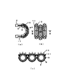
図2(図2(a)は伝熱管2の一部側面図を示し、図2(b)には図2(a)の矢印A方向からの矢視図であり、図2(c)は図2(b)のB−B線矢視図を示す。)に示す実施の形態において、伝熱管2のベンド部にプロテクタ8を設け、該プロテクタ8の外側表面に円柱形状のスタッド10を取り付ける。また、図2(b)に示すように伝熱管2の軸方向にスタッド10を千鳥配置する。これにより成長過程の気泡をスタッド10により細分することができ、同時にプロテクタ8の外表面での流動媒体1の通過速度を直管部における流動媒体1の通過速度と同程度に緩和させることができることを実試験で確認している。
【0024】
また、伝熱管2のベンド部におけるプロテクタ構造にさらに、隣接するプロテクタ8同士の隙間を塞ぐようにベンド部の曲がり管形状に沿った長いU字型の丸鋼11を一対以上取り付けることができる。
【0025】
図2に示す構成では、流動層ボイラの炉幅方向に並ぶ伝熱管2のベンド部はスタッド10を取り付けたプロテクタ8を設置しても隣接管との間にわずかな隙間を生じ、この隙間に集中して流動媒体1が流れ込む現象が生じる。前記わずかな隙間が存在すると圧力損失を生じ、流動媒体の運動エネルギーが速度エネルギーに変換され、高速でこの隙間を通り過ぎるため、当該ベンド部表面と同様に左右両側面も過酷な摩耗条件にさらされることになる。この隙間を丸鋼11で埋めることにより流動媒体1の高速通過を阻害することが可能となる。これにより当該ベンド部に設けたプロテクタ8の左右側面に取り付けてある継ぎ板9の健全性が保たれ、プロテクタ8の捲れや脱落を防止することができる。
【0026】
また、流動層ボイラの運転を停止させた後にメンテナンスあるいはボイラ内部の点検を行う場合、ボイラ内から流動媒体1を取り除く必要があるが、この際に上段ベッドの流動媒体1は抜出管6から直接下段ベッドへ落下させるため、流動媒体1が下段ベッドの伝熱管2を直撃することから極端な摩耗が予想される。
【0027】
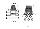
そこで、図3(図3(a)は伝熱管部分の側面図、図3(b)は図3(a)のA−A線断面矢視図)に示すように、伝熱管2の直管部に一対の半割れプロテクタ8を継ぎ板9で溶接接続して伝熱管2の直管部を覆い、プロテクタ8の上半分表面の管軸方向に任意の長さで複数の丸鋼12を並列に配置して取り付ける。これにより、上段ベッドから落下してくる流動媒体1を積極的に隣接する丸鋼12同士の間に堆積させることができ、流動媒体1が直接プロテクタ8の表面に接触することを防止する。こうしてプロテクタ8が摩耗、摩滅することはなくなり、伝熱管2自体の損傷も防げる。
【図面の簡単な説明】
【図1】流動層ボイラの全体概念図を示す。
【図2】図2(a)は伝熱管2の一部側面図を示し、図2(b)には図2(a)の矢印A方向からの矢視図であり、図2(c)は図2(b)のB−B線矢視図を示す。
【図3】図3(a)は伝熱管部分の側面図、図3(b)は図3(a)のA−A線断面矢視図を示す。
【図4】図4(a)は従来技術のベンド部の伝熱管2の側面図を示し、図4(b)は図4(a)の矢印A方向からの矢視図であり、図4(c)は図4(b)のB−B線矢視図を示す。
【図5】図5(a)は従来技術の直管部の伝熱管2の側面図を示し、図5(b)には図5(a)のA−A線矢視図を示す。
【図6】図5に示すプロテクタ8を設けた伝熱管2の断面図を示す。
【符号の説明】
1 流動媒体 2 伝熱管
3 風箱 3a 起動用風箱セル
4 空気 4a 燃焼ガス
5 分散板 6 抜出管
7 サポート 8 プロテクタ
9 継ぎ板 10 スタッド
11、12 丸鋼 13 摩耗部位
14 プロテクタ捲れ状態[0001]
[Industrial applications]
The present invention relates to a protector structure suitable for preventing wear and breakage of a heat transfer tube protector of a fluidized bed combustion device such as a fluidized bed boiler.
[0002]
[Prior art]
FIG. 1 is a schematic diagram showing the overall concept of a fluidized-bed boiler, which has a two-story system consisting of an upper fluidized bed and a lower fluidized bed. The upper fluidized bed consists of an MBC (main combustion furnace) upper bed and a CBC (reburning). Furnace bed) and the lower fluidized bed is composed of an MBC (main combustion furnace) lower bed. The heat transfer tube 2 includes a straight tube portion and a bent tube portion obtained by bending the straight tube portion. The straight tube portion is provided through the front wall of the MBC or the rear wall of the CBC, and is provided in a bed filled with the fluid medium 1. It is supported by several supports 7 standing upright from the dispersion plate 5.
[0003]
The bed filled with the fluid medium 1 on the dispersing plate 5 is supplied with air 4 from the wind box 3 provided below the dispersing plate 5 via the fine holes of the dispersing plate 5. 1 is fluidized to form a fluidized bed in the bed, and at the same time, fuel supplied from a fuel supply device (not shown) provided on the dispersion plate 5 is burned in the fluidized bed. Water flowing in the heat transfer tube 2 in the fluidized bed, which has become hot due to the combustion of the fuel, absorbs heat to generate steam, and the combustion gas 4a is discharged from the bed to a flue (not shown).
[0004]
The wind box 3 is divided into a number of cells 3a. When the boiler is started, hot air is supplied to a specific cell 3a to fluidize only the fluid medium 1 immediately above the specific cell 3a. At this time, since air is not supplied to the cells 3a other than the specific cells 3a, the flowing medium 1 in the bed immediately above the cells 3a other than the specific cells 3a stops flowing and becomes a stationary layer.
[0005]
Fuel is supplied from the coal supply device above the cell 3a in a state where the specific cell 3a is sufficiently heated by the hot air, and combustion is started in the fluidized bed. Next, air is supplied to the adjacent cells 3a to cause the fluidized medium 1 on the cells 3a to flow, and then fuel is supplied to the fluidized beds and burned, and the fire is sequentially transferred to the adjacent cells 3a. As a result, load control is performed by controlling the entire heat transfer area due to the flow of the fluid medium 1.
[0006]
[Problems to be solved by the invention]
In the fluidized bed boiler shown in FIG. 1, in the upper and lower beds of the MBC except the CBC bed, the heat transfer tube 2 is not provided in the fluidized bed immediately above each of the specific cell 3a used when starting the boiler and the cell 3a adjacent thereto. However, even if there is only a bent tube tip portion (hereinafter sometimes referred to as a bend portion) of the heat transfer tube 2, the flow speed of the fluid medium 1 is much higher than that of the portion where the heat transfer tube 2 exists. Swiftly, the flowing air 4 grows into bubbles and grows, and the flowing-through phenomenon of the flowing medium 1 occurs. At this time, the kinetic energy of the fluid medium 1 is much larger than that of the normal fluid. Therefore, in the prior art, a protector 8 as shown in FIG. 4 was installed in order to prevent the heat transfer tube 2 in the bend portion from being damaged by wear. 4A is a side view of the heat transfer tube 2 at the bend portion, FIG. 4B is a view from the direction of arrow A in FIG. 4A, and FIG. FIG. 3B is a view taken along line BB of FIG.
[0007]
The protector 8 shown in FIG. 4 has a structure in which a cylinder is formed in a half-shape. After covering the side surface of the heat transfer tube 2 with a pair of half-break protectors 8, the opposite ends of the pair of half-break protectors 8 are joined. Weld with plate 9. As shown in FIGS. 4 (a) and 4 (b), a plurality of a pair of half-break protectors 8 are arranged in series to form a protector configuration at a bend portion of the heat transfer tube 2, but the operation time of the boiler is reduced. When the predetermined time or more is reached, the outer surface of the tip portion of the protector 8 in the bend portion is worn out due to wear due to the blow-through action of the fluid medium 1 or the welded portion of the joint plate 9 is worn out. A phenomenon that the outer surface is curled up frequently occurs, and further, the thickness of the exposed heat transfer tube 2 may be reduced.
[0008]
If a through-hole is formed in the heat transfer tube 2 due to the repetition of such a phenomenon, it causes a tube leak. Reproducing and repairing the protector 8 for each periodic inspection in order to prevent the occurrence of the tube leak has a problem in that the material cost, the processing cost, and the labor cost for installation are enormous. In particular, when the protector 8 is attached to the heat transfer tube 2, since the heat transfer tubes 2 are densely arranged in the furnace width direction, when performing the setting work of the protector 8 and the welding work of the joint plate 9, the adjacent heat transfer tubes 2 are connected. It is necessary to bend by an unreasonable external force to create a work space, and there is also a problem in terms of the structural strength and soundness of the heat transfer tube 2.
[0009]
Next, when the maintenance of the MBC upper bed and the CBC bed is performed when the boiler is stopped, the fluid medium 1 is dropped from the MBC upper bed and the CBC bed to the MBC lower bed using the extraction pipe 6 shown in FIG. However, at this time, since the lower bed of the MBC also stops flowing, the straight pipe section on the upper side of the heat transfer tube 2 in the lower bed of the MBC is exposed from the fluid medium 1, and the upper bed of the MBC and The structure is such that the fluid medium 1 falls from the CBC bed.
[0010]
In order to prevent the heat transfer tube 2 in the lower bed of the MBC from being worn out and damaged by the drop of the fluid medium 1, in the prior art, as shown in FIG. The protector 8 is installed at the part where the fluid medium 1 falls. FIG. 5A shows a side view of the heat transfer tube 2 of the straight pipe portion, and FIG. 5B shows a view taken along line AA of FIG. 5A.
[0011]
FIG. 6 shows a cross-sectional view of the heat transfer tube 2 provided with the protector 8 shown in FIG. 5, and this protector 8 has basically the same structure as the protector 8 shown in FIG. The end portions of a pair of protectors 8 obtained in the form of a pipe are welded together with a connecting plate 9 and installed in a straight pipe portion. FIG. 6 shows the collision of the fluid medium 1 falling from the MBC upper bed and the CBC bed. As a result, the upper surface of the protector 8 is reduced in thickness as shown in FIG. 1, and when the protector 8 is worn out, it becomes a factor of reducing the thickness of the heat transfer tube 2 as a problem.
[0012]
As described above, the protector 8 is provided to prevent the wear of the heat transfer tube 2 in the above-described related art, but no measures are taken to prevent the protector 8 from being worn.
[0013]
Therefore, an object of the present invention is to prevent wear of a protector of a heat transfer tube of a fluidized-bed combustion device, and to make it possible to semipermanently use the protector, which has conventionally been treated as a consumable.
[0014]
[Means for Solving the Problems]
The above object of the present invention is solved by the following configuration.
The invention according to claim 1 is a fluidized bed combustion apparatus having a fluidized bed in which a heat transfer tube having a straight tube portion and a bent tube portion is installed in a fluidized medium filling portion and fuel is burned while fluidizing the fluidized medium. , At least the outer surface of the bent tube portion of the heat transfer tube is covered with a protector, a plurality of studs are provided to provide resistance to the fluid flowing outside the protector tube, and the bent portions of the heat transfer tube are provided on both left and right side surfaces of the protector. This is a fluidized bed combustion apparatus in which a U-shaped round bar is installed along the shape of a circle.
[0015]
The invention according to claim 2 is the fluidized bed combustion apparatus according to claim 1, wherein the studs are staggered in the axial direction of the heat transfer tube.
[0016]
According to a third aspect of the present invention, the fluidized bed is composed of two layers, an upper fluidized bed and a lower fluidized bed, and has a configuration in which a fluid medium can be extracted from the upper fluidized bed to the lower fluidized bed. At least the uppermost heat transfer tube of the heat transfer tube installed near the drop site of the fluid medium from the bed and the vicinity thereof has a protector covering the outer surface thereof, and a plurality of round steel bars on the upper surface of the protector. 3. The fluidized bed combustion apparatus according to claim 1, wherein the apparatus is installed along an axial direction.
The fluidized bed combustion device of the present invention is a boiler, a refuse incinerator or the like.
[0017]
【The invention's effect】
According to the first aspect of the present invention, by providing a plurality of studs on at least the protector provided on the outer surface of the bent tube portion of the heat transfer tube, resistance is given to the fluid flowing outside the tube, and the flow energy is provided. It is possible to reduce the flow rate of the flowing medium on the wear surface of the wear-resistant protector, and it is possible to prevent wall loss and wear due to wear of the protector. By installing a U-shaped round steel along the shape of the bent part of the heat transfer tube, it is possible to close the gap between adjacent tubes, and it is possible to prevent the joint plate from being worn and worn by the flowing medium blow-through In addition, it is possible to prevent the protector from being turned over.
[0018]
As a result, it is possible to drastically reduce the production and installation costs and cost of installation work by repairing the overlay of the heat transfer tube or updating the protector at each periodic inspection, and at the same time, maintaining the soundness of the heat transfer tube. Damage accidents can be prevented beforehand.
[0019]
According to the second aspect of the present invention, the studs are staggered in the axial direction of the heat transfer tube. In addition to the effect of the first aspect, the flow energy of the fluid medium can be further reduced. In addition, the effect of preventing wall thinning and abrasion due to wear of the protector is further enhanced.
[0020]
According to the third aspect of the present invention, in addition to the effects of the first or second aspect, at least the most part of the heat transfer tube installed in the lower fluidized bed at the location where the fluid medium falls from the upper fluidized bed and in the vicinity thereof. Since the protector and multiple round bars are installed in the upper heat transfer tube, the flowing medium falling from the upper bed accumulates in the valley between the round bars, and it is possible to avoid collision with the protector directly. Thus, wear and abrasion of the protector can be prevented.
[0021]
BEST MODE FOR CARRYING OUT THE INVENTION
An embodiment of the present invention will be described with reference to the drawings.
As shown in FIG. 1, the fluidized bed boiler has an upper fluidized bed composed of an MBC (main combustion furnace) upper bed and a CBC (reburning furnace) bed, and a lower fluidized bed composed of an MBC (main combustion furnace) lower bed. ing. In the upper bed and the lower bed, the heat transfer tube 2 has a straight tube portion installed in a horizontal direction, and a bend portion is provided at a tip of the straight tube portion. The bend portion is located immediately above the start-up wind box cell 3a or on the cell 3a adjacent thereto, and since there is no heat transfer tube straight portion in this portion, the flowing air supplied from the wind box 3 becomes bubbles. Grows and blows through to the surface of the fluidized bed.
[0022]
Since the bend portion of the heat transfer tube 2 is exposed to this environment and is much more easily worn than the straight tube portion of the heat transfer tube 2, a pair of half-type protectors 8 are connected to the bend portion by a connecting plate 9, and the heat transfer tube is connected to the bend portion. The surface of the heat tube 2 is covered.
[0023]
2 (FIG. 2 (a) is a partial side view of the heat transfer tube 2, FIG. 2 (b) is a view from the direction of arrow A in FIG. 2 (a), and FIG. In the embodiment shown in FIG. 2B, the protector 8 is provided at the bend portion of the heat transfer tube 2 and the cylindrical stud 10 is attached to the outer surface of the protector 8. . Further, as shown in FIG. 2B, the studs 10 are staggered in the axial direction of the heat transfer tube 2. As a result, the bubbles in the growth process can be subdivided by the studs 10, and at the same time, the passing speed of the flowing medium 1 on the outer surface of the protector 8 can be reduced to the same level as the passing speed of the flowing medium 1 in the straight pipe portion. Has been confirmed in actual tests.
[0024]
Further, more than one pair of long U-shaped round bars 11 along the bent pipe shape of the bend portion can be attached to the protector structure at the bend portion of the heat transfer tube 2 so as to close the gap between the adjacent protectors 8.
[0025]
In the configuration shown in FIG. 2, the bend portions of the heat transfer tubes 2 arranged in the furnace width direction of the fluidized-bed boiler have a slight gap between adjacent tubes even if the protector 8 to which the stud 10 is attached is formed. A phenomenon occurs in which the fluid medium 1 flows in a concentrated manner. When the small gap exists, a pressure loss occurs, the kinetic energy of the fluid medium is converted into velocity energy, and passes through the gap at a high speed, so that the left and right side surfaces as well as the bend surface are exposed to severe wear conditions. Will be. By filling the gap with the round bar 11, it is possible to prevent the fluid medium 1 from passing at high speed. Accordingly, the soundness of the joint plates 9 attached to the left and right side surfaces of the protector 8 provided in the bend portion is maintained, and the protector 8 can be prevented from being turned or dropped.
[0026]
When maintenance or inspection inside the boiler is performed after the operation of the fluidized bed boiler is stopped, it is necessary to remove the fluidized medium 1 from the inside of the boiler. Since the fluid medium 1 directly falls on the lower bed, the fluid medium 1 directly hits the heat transfer tube 2 of the lower bed, so that extreme wear is expected.
[0027]
Therefore, as shown in FIG. 3 (FIG. 3 (a) is a side view of the heat transfer tube portion, and FIG. 3 (b) is a sectional view taken along line AA of FIG. 3 (a)). A pair of half-split protectors 8 are connected by welding with a joint plate 9 to cover the straight pipe portion of the heat transfer tube 2, and a plurality of round bars 12 are arranged in parallel in an arbitrary length in the pipe axis direction on the upper half surface of the protector 8. And attach it. Accordingly, the fluid medium 1 falling from the upper bed can be positively deposited between the adjacent round bars 12, and the fluid medium 1 is prevented from directly contacting the surface of the protector 8. Thus, the protector 8 is not worn or worn away, and the heat transfer tube 2 itself can be prevented from being damaged.
[Brief description of the drawings]
FIG. 1 shows an overall conceptual diagram of a fluidized bed boiler.
2 (a) is a partial side view of the heat transfer tube 2, and FIG. 2 (b) is a view from the direction of arrow A in FIG. 2 (a), and FIG. 2 (c). 2 shows a view taken along the line BB in FIG. 2 (b).
3 (a) is a side view of a heat transfer tube portion, and FIG. 3 (b) is a sectional view taken along line AA of FIG. 3 (a).
4 (a) is a side view of a heat transfer tube 2 of a conventional bend portion, and FIG. 4 (b) is a view from the direction of arrow A in FIG. 4 (a). FIG. 4C is a view taken along line BB of FIG.
5 (a) is a side view of a conventional heat transfer tube 2 having a straight pipe portion, and FIG. 5 (b) is a view taken along line AA of FIG. 5 (a).
FIG. 6 is a sectional view of the heat transfer tube 2 provided with the protector 8 shown in FIG.
[Explanation of symbols]
DESCRIPTION OF SYMBOLS 1 Fluid medium 2 Heat transfer tube 3 Wind box 3a Start-up wind cell 4 Air 4a Combustion gas 5 Dispersion plate 6 Extraction tube 7 Support 8 Protector 9 Splicing plate 10 Stud 11, 12 Round steel 13 Wear part 14 Protector turned state