JP2004019190A - Closure mechanism for door - Google Patents

Closure mechanism for door Download PDF

Info

Publication number
JP2004019190A
JP2004019190A JP2002173686A JP2002173686A JP2004019190A JP 2004019190 A JP2004019190 A JP 2004019190A JP 2002173686 A JP2002173686 A JP 2002173686A JP 2002173686 A JP2002173686 A JP 2002173686A JP 2004019190 A JP2004019190 A JP 2004019190A
Authority
JP
Japan
Prior art keywords
door
push
hook member
pull handle
engagement
Prior art date
Legal status (The legal status is an assumption and is not a legal conclusion. Google has not performed a legal analysis and makes no representation as to the accuracy of the status listed.)
Granted
Application number
JP2002173686A
Other languages
Japanese (ja)
Other versions
JP3951172B2 (en
Inventor
Satoru Hara
原 悟
Current Assignee (The listed assignees may be inaccurate. Google has not performed a legal analysis and makes no representation or warranty as to the accuracy of the list.)
Howa Machinery Ltd
Original Assignee
Howa Machinery Ltd
Priority date (The priority date is an assumption and is not a legal conclusion. Google has not performed a legal analysis and makes no representation as to the accuracy of the date listed.)
Filing date
Publication date
Application filed by Howa Machinery Ltd filed Critical Howa Machinery Ltd
Priority to JP2002173686A priority Critical patent/JP3951172B2/en
Publication of JP2004019190A publication Critical patent/JP2004019190A/en
Application granted granted Critical
Publication of JP3951172B2 publication Critical patent/JP3951172B2/en
Anticipated expiration legal-status Critical
Expired - Fee Related legal-status Critical Current

Links

Images

Abstract

<P>PROBLEM TO BE SOLVED: To provide a closure mechanism for door which can make a usually closed door in opened state without rotating a handle and can make the usually closed door in a state of being pushed to the door frame. <P>SOLUTION: A latch mechanism 4 comprising a hook member 6 turnably supported on a door frame 2 and an engage member 7 turnably installed on a door 3 is so formed that an engagement part 7a provided in the engagement member 7 by the usual closure of the door 3 engages with the hook member 6, and the latch mechanism 4 is disengaged by operating a pushing-drawing handle 5 installed on the door 3, and the door 3 is brought into a pressing state to the door frame 2 through the latch mechanism 4 by the operation of the pushing-drawing handle 5. <P>COPYRIGHT: (C)2004,JPO

Description

【0001】
【発明の属する技術分野】
本発明は、扉枠と、その扉枠に開閉自在に蝶着された扉との間に介在されたラッチ機構を、扉に設けた操作手段を操作することにより解除し、また、その操作手段の操作により前記ラッチ機構を介して扉を扉枠に押付状態とする扉の閉鎖機構に関する。
【0002】
【従来の技術】
上記した扉の閉鎖機構として、特開2001−132304号公報のクレモンロック装置が知られている。そのクレモンロック装置は、扉に設置したラッチボルトと固定枠体(扉枠)に設置した受金とから成るラッチ機構を介して、扉を閉鎖位置に錠止(扉の通常閉鎖)することができる。そして、扉が閉鎖位置に錠止された状態において、扉に設けたハンドル(ドアノブ)を解錠方向に回転すると、扉を開放状態とすることができる。また、扉が閉鎖位置に錠止された状態において、前記ハンドルを施錠方向(解錠方向とは逆方向)に回転すると、扉を固定枠体(扉枠)に押付状態とすることができる。
【0003】
【発明が解決しようとする課題】
上記のクレモンロック装置では、通常閉鎖の扉を開放する場合や、通常閉鎖の扉を扉枠に押付状態とする場合には、扉に設けたハンドルを握って解錠(施錠)方向に回転しなければならない。そのために、ハンドルを回転させることが困難な者(例えば手の不自由な者や握力が低下した老人等)においては、通常閉鎖の扉を開放したり、通常閉鎖の扉を扉枠に押付状態とすることが容易ではない。また、健常者であっても、両手が使えない場合には、ハンドルを握って回転させることが出来ない。そこで、本発明の課題は、ハンドルを回転させることなく、通常閉鎖の扉を開放状態とし、また、通常閉鎖の扉を扉枠に押付状態とすることができる扉の閉鎖機構を提供することにある。
【0004】
【課題を解決するための手段】
上記課題解決のため、本願では、扉枠と、その扉枠に開閉自在に蝶着された扉との間に介在されたラッチ機構を、扉に設けた操作手段を操作することにより解除し、また、その操作手段の操作により前記ラッチ機構を介して扉を扉枠に押付状態とする扉の閉鎖機構において、上記操作手段を、扉に設けた押し引きハンドルとした。その押し引きハンドルは、扉に所定角度揺動するように取り付けてある。そして、扉枠にフック部材を回動自在に支持し、そのフック部材の先端が扉側に突出するようにフック部材を付勢し、扉には上記フック部材と係脱する係合部を備えた係合部材を回動可能に設けてラッチ機構を構成し、扉の通常閉鎖により係合部材の係合部がフック部材と係合するようにした。
【0005】
前記フック部材の回動軸線と係合部材の回動軸線とが平行であり、扉にはフック部材を押し出す押し出し部材を備え、押し引きハンドルの操作により上記押し出し部材がフック部材と係合部材との係合を解除して扉を開放可能とし、また、押し引きハンドルの操作で、扉を扉枠に押し付けるように係合部材をフック部材に対して回転移動させるように押し引きハンドルと係合部材とを連繋した。
【0006】
具体的に、扉にフック部材の回動軸線と平行に支持軸を設け、その支持軸に係合部材と押し引きハンドルを取り付けるカム体を揺動自在に支持して、押し引きハンドルを前記支持軸を揺動中心として中立位置とその両側で所定角度揺動した2つの揺動端位置とに揺動するようにし、扉の通常閉鎖時に係止部材とフック部材とが係合している状態において、中立位置にある前記押し引きハンドルを前記一方の揺動端位置としたときには、カム体に設けた動作カムと係合部材とが係合せず押し出し部材がフック部材を押し出し、他方の揺動端位置としたときには、カム体に設けた動作カムと係合部材とが係合して扉を扉枠に押し付けるように係合部材をフック部材に対して回転移動させるように構成した。
【0007】
更に、フック部材の回動軸線と係合部材の回動軸線とが直角を成して配置され、その係合部材のフック側面には、フック部材と係脱する係合部と、押し引きハンドルの操作で係合部材が回転した時にフック部材を押し出してフック部材と係合部材との係合を解除する解除部分と、フック部材と係合部との係合状態において押し引きハンドルの操作で係合部材が前記と逆に回転した時に、フック部材を介して扉を扉枠に押し付ける押し付け面とを備えた。前記押し引きハンドルを中立位置とその両側で所定角度揺動した2つの揺動端位置とに揺動するように扉に取り付け、その揺動により係合部材が回転して解除部分がフック部材を押し出す押し出し角度位置と押し付け面がフック部材を介して扉を扉枠に押し付ける押し付け角度位置とに揺動するように連繋した。
【0008】
【発明の実施の形態】
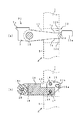
実施の形態について図面を参照して説明する。図1〜5に示す扉の閉鎖装置1は、扉枠2と、その扉枠2に開閉自在に蝶着された扉3との間に介在されたラッチ機構4を、扉3に設けた押し引きハンドル5を操作することにより解除し、また、その押し引きハンドル5の操作により前記ラッチ機構4を介して扉3を扉枠2に押付状態とするものである。前記ラッチ機構4は、扉3の戸先部分の上下方向中間に設けてあり、扉枠2(竪枠2a)に回動自在に支持されたフック部材6と、扉3に回動可能に設けられた係合部材7とから成り、扉3の通常閉鎖(図1の状態)により係合部材7に備えた係合部7aがフック部材6と係合するようになっている。
【0009】
竪枠2aに回動自在に支持されたフック部材6の先端6aが扉3側に突出し、かつ、扉3の開扉方向にフック部材6はバネ部材8によって付勢されている。扉3に取り付けられたケース下板9aには、前記フック部材6の回動軸線と平行に支持軸10が設けられている。その支持軸10には、フック部材6と係脱する係合部7aを備えた係合部材7とカム体11が夫々別々に揺動自在に支持されている。カム体11に押し引きハンドル5を一体に取り付けたことから、押し引きハンドル5は、支持軸10を揺動中心として中立位置Aとその両側で所定角度揺動した2つの揺動端位置B,Cとに揺動する。
【0010】
前記カム体11の下部には、2つの突起部12a,12bから成る動作カム12が設けられている。突起部12a,12b間に、係合部材7の後部が所定の隙間を持って配置されている。第1突起部12aは、押し引きハンドル5が中立位置Aにある状態(図6)において、通常の係止位置P1にある係合部材側面7bに当接するように形成されている。第2突起部12bは、押し引きハンドル5が一方の揺動端位置(解錠位置)Bにある状態(図7)において、通常の係止位置P1にある係合部材側面7cに当接するように形成されている。
【0011】
押し引きハンドル5を中立位置Aから一方の揺動端位置Bに揺動させた場合では、第1、第2突起部12a,12bにより、通常の係止位置P1にある係合部材7は回動しない。そして、一方の揺動端位置Bから中立位置Aに揺動させた場合でも、第1、第2突起部12a,12bにより、通常の係止位置P1にある係合部材7は回動しない。次に、押し引きハンドル5を中立位置Aから他方の揺動端位置(扉押付位置)Cに揺動させた場合では、第1突起部12aにより、通常の係止位置P1にある係合部材側面7bが押されて、係合部材7は押付位置P2へと回動する(図8)。また、押付位置P2にある係合部材7に対して押し引きハンドル5を他方の揺動端位置Cから中立位置Aに揺動させた場合では、第1、第2突起部12a,12bにより、押付位置P2にある係合部材7は回動しないが、一方の揺動端位置Bまで揺動させた場合では、第2突起部12bにより、係合部材7は回動して通常の係止位置P1に戻る(図7)。
【0012】
ケース後板9bには、複数のプランジャ13a,13bが取り付けてある。そして、支持軸10に支持された係合部材7の後面とカム体11の後面に、前記プランジャ13a,13bが嵌まり込む溝7d,11aが形成されている。一方のプランジャ13aは、押し引きハンドル5が他方の揺動端位置Cに揺動されて、押付位置P2に回動した係合部材7の溝7dに嵌まり込むように配置されている(図8)。もう一方13bは、押し引きハンドル5が中立位置Aにある状態のカム体11の溝11aに嵌まり込むように配置されている(図3)。また、一方のプランジャ13aの押付力は、押付位置P2に回動した係合部材7をその位置に弾性的に保持するように設定されている。もう一方のプランジャ13bの押付力は、押し引きハンドル5を用いて扉3の開閉を行う時に、中立位置Aにある押し引きハンドル5が揺動しないように弾性的に保持するように設定されている。
【0013】
前記ケース上板9cには、支持軸10と平行に第1軸部材14が設けられている。その第1軸部材14には、三角形状の作動カム15が揺動自在に支持されている。作動カム15には第1長孔15aと支持孔15bが形成されており、第1長孔15aには、カム体11の上部に設けた突起部11bが係合している。ケース上板9cとケース中間板9dとの間には、先端にローラ部材16aを備えた押し出し部材16が配置されており、その押し出し部材16の後端部には第2軸部材17が嵌め込まれている。第2軸部材17の一方の端部は、ケース上板9cに設けた第1長孔18に係合し、もう一方の端部は、作動カム15の支持孔15bを貫通してケース中間板9dに設けた第2長孔19に係合している。また、前記ローラ部材16aを保持している第3軸部材20の一方の端部は、ケース上板9cに設けた第3長孔21に係合し、もう一方の端部は、ケース中間板9dに設けた第4長孔22に係合している。
【0014】
このことから、図7に示すように、押し引きハンドル5を中立位置Aから一方の揺動端位置Bに揺動すると、カム体11の突起部11bを介して作動カム15が揺動し、作動カム15の揺動により第2軸部材17が第1,2長孔18,19に沿って扉3の戸先方向に向けて移動する。これにより、押し出し部材16は第3,4長孔21,22に沿って扉3の戸先方向に移動する。次に、図8に示すように、押し引きハンドル5を中立位置Aから他方の揺動端位置Cに揺動すると、カム体11の突起部11bを介して作動カム15が揺動し、作動カム15の揺動により第2軸部材17が第1,2長孔18,19に沿って扉3の吊元方向に向けて移動する。そして、押し出し部材16は第3,4長孔21,22に沿って扉3の吊元方向に移動する。尚、本実施形態では、押し出し部材16の扉3の戸先方向への移動量を、ローラ部材16a側面が扉3の端面3aと略同一位置となるように設定してある。
【0015】
上記のように構成されたラッチ機構4を備えた扉3の閉鎖装置1の動作について説明する。扉3が扉枠2から開放されている時には、竪枠2aのフック部材6はバネ部材8によって先端6aが扉3側に突出している。扉3に設けた押し引きハンドル5は、プランジャ13bによって中立位置Aに保持されている。また、係合部材7は、通常の係止位置P1にある。この状態において、扉3を閉鎖回転させる。図9に示すように、扉3が閉鎖位置に近づくと、扉3の端面3a及び押し出し部材16のローラ部材16aによって、フック部材6が竪枠2a内側に押し付けられる。その後、図3に示すように、扉3が閉鎖位置に移動すると、押し付けられていたフック部材6がバネ部材8によって扉3側に突出し、フック部材6の先端6aが係合部材7の係合部7aに係合することで、扉3の通常閉鎖が行われる。また、従来のラッチボルトが受金に摺動しながら係合する時に発生する音に比べて、係合部材7がフック部材6を押し付けながら係合する時に発生する音が小さいものとなる。
【0016】
先ず、扉3の通常閉鎖状態から扉3を開放させる場合について説明する。図10に示すように、中立位置Aにある押し引きハンドル5を一方の揺動端位置Bに揺動することで、カム体11を回動させる。カム体11の回動により、作動カム15を介して押し出し部材16が扉3の戸先方向に移動する。すると、押し出し部材16に備えたローラ部材16aによって、フック部材6が竪枠2a内側に押し付けられ、フック部材6と係合部材7との係合が解除される。また、カム体11が回動しても動作カム12と係合部材7とが係合せず、通常の係止位置P1にある係合部材7は回動しない。その後、一方の揺動端位置Bにある押し引きハンドル5を、扉3の開扉方向に引く(押す)ことで、扉3を開放させることができる。尚、フック部材6と係合部材7との係合を解除した後、押し引きハンドル5を中立位置Aに戻し、その状態で扉3を引く(押す)ことを行ってもよい。
【0017】
次に、扉3の通常閉鎖状態から扉3を扉枠2に押し付ける場合について説明する。図11に示すように、中立位置Aにある押し引きハンドル5を他方の揺動端位置Cに揺動することで、カム体11を回動させる。カム体11の回動により、作動カム15を介して押し出し部材16が扉3の吊元方向に移動する。そして、カム体11の回動により、動作カム12と係合部材7とが係合して、扉3を扉枠2に設けたパッキン部材23に押し付けるように、係合部材7をフック部材6に対して回転移動させる。係合部材7はプランジャ13aによってその位置P2に保持されるので、扉3を扉枠2に押付状態とすることができる。従って、ハンドルを回転させることが困難な者であっても、押し引きハンドル5を揺動(押し引き)することで、通常閉鎖の扉3を開放させることや、通常閉鎖の扉3を扉枠2に押付状態とすることが可能となる。
【0018】
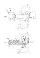
次に、別の実施形態について説明する。図12に示す扉3の閉鎖装置1は、上記と同様に、ラッチ機構30を、扉3に設けた押し引きハンドル5を操作することにより解除し、また、その押し引きハンドル5の操作により前記ラッチ機構30を介して扉3を扉枠2に押付状態とするものである。ラッチ機構30は、扉3の戸先部分の上部に設けてあり、扉枠2(上枠2b)に回動自在に支持されたフック部材31と、扉3の戸先上部に回動可能に設けられた係合部材32とから成り、扉3の通常閉鎖により係合部材32がフック部材31と係合するようになっている。
【0019】
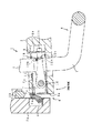
上枠2bに回動自在に支持されたフック部材31の先端31aが扉3側(下側)に突出し、かつ、扉3の開扉方向にバネ部材33によって付勢されている。扉3の戸先部分の上下方向中間に取り付けられたケース34の下板34aには、前記フック部材31の回動軸線と直角に支持軸35が設けられている。その支持軸35に押し引きハンドル5を取り付けるカム体36が揺動自在に支持されている。その揺動自在のカム体36を介して押し引きハンドル5は、支持軸35を揺動中心として中立位置Aとその両側で所定角度揺動した2つの揺動端位置B,Cとに揺動する。カム体36の上面には位置決め部材37が設置してある。その位置決め部材37には複数の切欠溝37a,37bが形成してある。そして、ケース34にはプランジャ38が取り付けてあり、前記一方の溝37aに嵌まり込むと、カム体36を介して押し引きハンドル5が中立位置Aに弾性的に保持される{図15(a)}。もう一方の溝37bに嵌まり込むと、カム体36を介して押し引きハンドル5が他方の揺動端位置Cに弾性的に保持される{図15(c)}。
【0020】
ケース34には軸部材39が回動自在に配置されており、軸部材39の下端部には溝39aが形成されている。その溝39aに係合する動作カム40がカム体36の上部に設けられている。押し引きハンドル5を中立位置Aから一方の揺動端位置Bに揺動させた場合では、動作カム40によって軸部材28は回転する{図15(b)}。次に、押し引きハンドル5を中立位置Aから他方の揺動端位置Cに揺動させた場合では、動作カム40によって軸部材39は前記と逆方向に回転する{図15(c)}。この軸部材39の先端には係合部材32が取り付けてある。このことにより、押し引きハンドル5の操作により、係合部材32をフック部材31の回動軸線と直交する軸線回りに回動させることができる。
【0021】
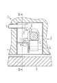
図17に示すように、係合部材32のフック側面には、フック部材31と係脱する係合部32aと、押し引きハンドル5の操作で係合部材32が回転した時にフック部材31を押し出してフック部材31と係合部材32との係合を解除する解除部分32bと、フック部材31と係合部32aとの係合状態において押し引きハンドル5の操作で係合部材32が前記と逆に回転した時に、フック部材31を介して扉3を上枠2bに押し付ける押し付け面32cとを備えている。前記係合部材32と軸部材39との取り付け位置関係は、押し引きハンドル5が一方の揺動端位置Bに揺動する場合には、係合部材32が回転して解除部分32bがフック部材31を押し出す押し出し角度位置Dに揺動するようにしてあり、押し引きハンドル5が他方の揺動端位置Cに揺動する場合には、係合部材32が回転して押し付け面32cがフック部材31を介して扉3を上枠2bに押し付ける押し付け角度位置Eに揺動するようにしてある。
【0022】
前記ラッチ機構30を備えた扉3の閉鎖装置1の動作について説明する。扉3が扉枠2から開放されている時には、上枠2bのフック部材31はバネ部材33によって先端31aが扉3側に突出している。扉3に設けた押し引きハンドル5は、プランジャ38によって中立位置Aに保持されている。この状態において、扉3を閉鎖回転させる。図18に示すように、扉3が閉鎖位置に近づくと、扉3の端面3b及び係合部材32によって、フック部材31が上枠2b内側に押し上げられる。その後、図16に示すように、扉3が閉鎖位置に移動すると、押し上げられていたフック部材31がバネ部材33によって扉3側(下側)に突出し、フック部材31の先端31aが係合部材32の係合部32aに係合することで、扉3の通常閉鎖が行われる。
【0023】
先ず、扉3の通常閉鎖状態から扉3を開放させる場合について説明する。図19に示すように、中立位置Aにある押し引きハンドル5を一方の揺動端位置Bに揺動することで、カム体36を回動させる。カム体36の回動により、軸部材39を介して係合部材32を押し出し角度位置Dに回転させる。すると、係合部材32の解除部分32bによってフック部材31が上枠2bに向けて押し上げられ、フック部材31と係合部材32との係合が解除される。その後、一方の揺動端位置Bにある押し引きハンドル5を、扉3の開扉方向に引く(押す)ことで、扉3を開放させることができる。
【0024】
次に、扉3の通常閉鎖状態から扉3を扉枠2に押し付ける場合について説明する。図21に示すように、中立位置Aにある押し引きハンドル5を他方の揺動端位置Cに揺動することで、カム体36を回動させる。カム体36の回動により、軸部材39を介して係合部材32を押し付け角度位置Eに回転させる。すると、係合部材32が、扉3を扉枠2に設けたパッキン部材23を押し付けるようにフック部材31に対して移動する。係合部材32はプランジャ38によってその位置Eに保持されるので、扉3を扉枠2に押付状態とすることができる。従って、ハンドルを回転させることが困難な者であっても、押し引きハンドル5を揺動(押し引き)することで、通常閉鎖の扉3を開放させることや、通常閉鎖の扉3を扉枠2に押付状態とすることが可能となる。尚、ラッチ機構30を扉3の戸先部分の上部に設けた扉3の閉鎖装置1について説明したが、ラッチ機構30を扉3の戸先部分の下部に設けてもよい。また、ラッチ機構30を扉3の戸先部分の上下部に夫々設けることで、1個所で扉3を扉枠2に押し付けることより押付力が増すことになる。更に、上述した実施形態のラッチ機構4を組み込むことで、扉3を扉枠2に押し付ける押付力がより増すことになる。
【0025】
【発明の効果】
以上のように本願では、扉に設けた押し引きハンドルの操作により、扉のラッチの開放と、ラッチを介して扉を扉枠に押し付ける動作を行うことができ、従来のように、ドアノブを握ってこれらの動作を行うものと比較して、握力の劣る老人等にとって、非常に操作しやすいという利点がある。
【図面の簡単な説明】
【図1】本発明の閉鎖装置を備えた扉枠に開閉自在に蝶着された扉である。
【図2】図1のP部の詳細図である。
【図3】図2のIII−III線断面図である。
【図4】図2のIV−IV線断面図である。
【図5】図2のV−V線断面図である。
【図6】押し引きハンドル(カム体)と係合部材及び押し出し部材との関係を示す図である。
【図7】押し引きハンドル(カム体)と係合部材及び押し出し部材との関係を示す図である。
【図8】押し引きハンドル(カム体)と係合部材及び押し出し部材との関係を示す図である。
【図9】扉を閉鎖回転させた状態を示す図である。
【図10】通常閉鎖状態から扉を開放させる状態を示す図である。
【図11】通常閉鎖状態から扉を扉枠に押し付ける状態を示す図である。
【図12】別の実施形態を示す図である。
【図13】図12のQ部の詳細図である。
【図14】図13のXIV―XIV線断面図である。
【図15】押し引きハンドル(カム体)と軸部材との関係を示す図である。
【図16】図12のXVI−XVI線断面図である。
【図17】図16のXVII−XVII線断面図である。
【図18】扉を閉鎖回転させた状態を示す図である。
【図19】通常閉鎖状態から扉を開放させる状態を示す図である。
【図20】図19のXX−XX線断面図である。
【図21】通常閉鎖状態から扉を扉枠に押し付ける状態を示す図である。
【図22】図21のXXII−XXII線断面図である。
【符号の説明】
1  閉鎖装置
2  扉枠
3  扉
4,30 ラッチ機構
5  押し引きハンドル
6,31 フック部材
6a,31a 先端
7,32 係合部材
7a,32a 係合部
10  支持軸
11  カム体
12  動作カム
16  押し出し部材
32b 解除部分
32c 押し付け面
A  中立位置
B  一方の揺動端位置
C  他方の揺動端位置
D  押し出し角度位置
E  押し付け角度位置
[0001]
TECHNICAL FIELD OF THE INVENTION
According to the present invention, a latch mechanism interposed between a door frame and a door hinged to the door frame so as to be opened and closed is released by operating an operating means provided on the door, and The present invention relates to a door closing mechanism for pressing the door against the door frame via the latch mechanism by the operation of (1).
[0002]
[Prior art]
As a door closing mechanism described above, there is known a clemon lock device disclosed in JP-A-2001-132304. The clemon lock device can lock the door at the closed position (normally closing the door) via a latch mechanism including a latch bolt installed on the door and a receiver installed on the fixed frame (door frame). it can. When the handle (door knob) provided on the door is rotated in the unlocking direction in a state where the door is locked at the closed position, the door can be opened. When the handle is rotated in the locking direction (the direction opposite to the unlocking direction) in a state where the door is locked in the closed position, the door can be pressed against the fixed frame (door frame).
[0003]
[Problems to be solved by the invention]
In the above-described clemon lock device, when the normally closed door is opened or the normally closed door is pressed against the door frame, the handle provided on the door is gripped and the door is rotated in the unlocking (locking) direction. There must be. Therefore, for those who have difficulty in turning the handle (for example, the handicapped or the elderly with reduced grip strength), the normally closed door is opened or the normally closed door is pressed against the door frame. It is not easy. In addition, even if it is a healthy person, if both hands cannot be used, it is not possible to hold and rotate the handle. Therefore, an object of the present invention is to provide a door closing mechanism capable of setting a normally closed door to an open state without rotating a handle and pressing the normally closed door against a door frame. is there.
[0004]
[Means for Solving the Problems]
In order to solve the above-mentioned problem, in the present application, a latch mechanism interposed between a door frame and a door hinged to the door frame so as to be opened and closed is released by operating an operating means provided on the door, Further, in the door closing mechanism in which the door is pressed against the door frame via the latch mechanism by operating the operating means, the operating means is a push-pull handle provided on the door. The push-pull handle is attached to the door so as to swing at a predetermined angle. Then, the hook member is rotatably supported by the door frame, the hook member is biased so that the tip of the hook member protrudes toward the door, and the door includes an engaging portion that engages with and disengages from the hook member. The engaging member is provided rotatably to constitute a latch mechanism, and the engaging portion of the engaging member is engaged with the hook member when the door is normally closed.
[0005]
The rotation axis of the hook member and the rotation axis of the engagement member are parallel to each other, and the door is provided with an extruding member for extruding the hook member. And the door can be opened by releasing the engagement of the push-pull handle, and the push-pull handle is engaged with the push-pull handle to rotate the engaging member with respect to the hook member so as to press the door against the door frame. The members were connected.
[0006]
Specifically, a support shaft is provided on the door in parallel with the rotation axis of the hook member, and a cam body on which the engaging member and the push / pull handle are mounted is swingably supported on the support shaft, and the push / pull handle is supported. A state where the locking member and the hook member are engaged when the door is normally closed when the shaft is swung between a neutral position and two swing end positions which are swung by a predetermined angle on both sides of the shaft. In the above, when the push / pull handle in the neutral position is set to the one swing end position, the operating cam provided on the cam body and the engaging member do not engage with each other, and the pushing member pushes out the hook member, and the other swinging position. When in the end position, the operation cam provided on the cam body is engaged with the engagement member to rotate the engagement member relative to the hook member such that the door is pressed against the door frame.
[0007]
Further, the rotation axis of the hook member and the rotation axis of the engagement member are arranged at a right angle, and the hook side surface of the engagement member has an engagement portion for engaging and disengaging the hook member, and a push-pull handle. When the engaging member is rotated by the operation described above, the hook member is pushed out to release the engagement between the hook member and the engaging member, and the push / pull handle is operated in the engaged state between the hook member and the engaging portion. A pressing surface for pressing the door against the door frame via the hook member when the engaging member rotates in the opposite direction. The push / pull handle is attached to the door so as to swing between a neutral position and two swing end positions which swing at a predetermined angle on both sides of the push / pull handle. The extruding angle position and the pressing surface are connected so as to swing to the pressing angle position for pressing the door against the door frame via the hook member.
[0008]
BEST MODE FOR CARRYING OUT THE INVENTION
Embodiments will be described with reference to the drawings. A door closing device 1 shown in FIGS. 1 to 5 includes a door frame 2 and a latch mechanism 4 interposed between the door frame 2 and a door 3 hinged to the door frame 2 so as to be openable and closable. The door 3 is released by operating the pull handle 5, and the door 3 is pressed against the door frame 2 via the latch mechanism 4 by operating the push handle 5. The latch mechanism 4 is provided at an intermediate position in the up-down direction of the door tip portion of the door 3, and is provided rotatably on the door 3 with a hook member 6 rotatably supported by the door frame 2 (vertical frame 2a). The engaging portion 7a provided on the engaging member 7 is engaged with the hook member 6 when the door 3 is normally closed (the state shown in FIG. 1).
[0009]
The tip 6a of the hook member 6 rotatably supported by the vertical frame 2a protrudes toward the door 3, and the hook member 6 is urged by a spring member 8 in the opening direction of the door 3. A support shaft 10 is provided on the case lower plate 9 a attached to the door 3 in parallel with the rotation axis of the hook member 6. On the support shaft 10, an engaging member 7 having an engaging portion 7a engaging and disengaging from the hook member 6 and a cam body 11 are separately swingably supported. Since the push / pull handle 5 is integrally attached to the cam body 11, the push / pull handle 5 is pivoted about the support shaft 10 at the neutral position A and at two swing end positions B, which swing at a predetermined angle on both sides thereof. Swing with C.
[0010]
An operation cam 12 including two protrusions 12a and 12b is provided below the cam body 11. The rear part of the engaging member 7 is arranged with a predetermined gap between the protrusions 12a and 12b. The first protrusion 12a is formed so as to come into contact with the engaging member side surface 7b at the normal locking position P1 when the push-pull handle 5 is at the neutral position A (FIG. 6). When the push / pull handle 5 is in the one swing end position (unlocked position) B (FIG. 7), the second protrusion 12b abuts on the engaging member side surface 7c at the normal locking position P1. Is formed.
[0011]
When the push / pull handle 5 is swung from the neutral position A to one of the swing end positions B, the first and second protrusions 12a and 12b rotate the engagement member 7 at the normal engagement position P1. Does not work. Then, even when swinging from one swing end position B to the neutral position A, the first and second projections 12a and 12b do not rotate the engaging member 7 at the normal locking position P1. Next, when the push / pull handle 5 is swung from the neutral position A to the other swing end position (door pressing position) C, the first protrusion 12a causes the engagement member in the normal engagement position P1. The side surface 7b is pushed, and the engaging member 7 rotates to the pushing position P2 (FIG. 8). When the push / pull handle 5 is swung from the other swing end position C to the neutral position A with respect to the engaging member 7 at the pressing position P2, the first and second protrusions 12a and 12b cause The engaging member 7 at the pressing position P2 does not rotate, but when the engaging member 7 is swung to the one swing end position B, the engaging member 7 is turned by the second protrusion 12b to perform normal locking. It returns to position P1 (FIG. 7).
[0012]
A plurality of plungers 13a and 13b are attached to the case rear plate 9b. Grooves 7d and 11a into which the plungers 13a and 13b fit are formed on the rear surface of the engaging member 7 supported by the support shaft 10 and the rear surface of the cam body 11. The one plunger 13a is arranged so that the push-pull handle 5 is swung to the other swing end position C and fitted into the groove 7d of the engaging member 7 rotated to the pressing position P2 (FIG. 8). The other 13b is disposed so as to fit into the groove 11a of the cam body 11 in a state where the push-pull handle 5 is at the neutral position A (FIG. 3). The pressing force of one plunger 13a is set so as to elastically hold the engaging member 7 rotated to the pressing position P2 at that position. The pressing force of the other plunger 13b is set such that when the door 3 is opened and closed using the push / pull handle 5, the push / pull handle 5 at the neutral position A is elastically held so as not to swing. I have.
[0013]
A first shaft member 14 is provided on the case upper plate 9c in parallel with the support shaft 10. On the first shaft member 14, a triangular operating cam 15 is swingably supported. A first elongated hole 15a and a support hole 15b are formed in the operation cam 15, and a projection 11b provided on an upper portion of the cam body 11 is engaged with the first elongated hole 15a. An extruding member 16 having a roller member 16a at the tip is disposed between the case upper plate 9c and the case intermediate plate 9d, and a second shaft member 17 is fitted into the rear end of the extruding member 16. ing. One end of the second shaft member 17 engages with a first elongated hole 18 provided in the case upper plate 9c, and the other end thereof penetrates through the support hole 15b of the operation cam 15 and a case intermediate plate. 9d is engaged with the second long hole 19 provided in 9d. One end of the third shaft member 20 holding the roller member 16a is engaged with a third elongated hole 21 provided in the case upper plate 9c, and the other end is connected to the case intermediate plate. It is engaged with the fourth long hole 22 provided in 9d.
[0014]
From this, as shown in FIG. 7, when the push / pull handle 5 is swung from the neutral position A to one of the swing end positions B, the operation cam 15 swings via the protrusion 11b of the cam body 11, and The swing of the operation cam 15 causes the second shaft member 17 to move toward the door tip of the door 3 along the first and second long holes 18 and 19. As a result, the extruding member 16 moves along the third and fourth long holes 21 and 22 toward the door tip of the door 3. Next, as shown in FIG. 8, when the push / pull handle 5 is swung from the neutral position A to the other swing end position C, the operating cam 15 swings via the protrusion 11b of the cam body 11, and the operating cam 15 swings. The swing of the cam 15 causes the second shaft member 17 to move in the hanging direction of the door 3 along the first and second long holes 18 and 19. Then, the extruding member 16 moves in the hanging direction of the door 3 along the third and fourth long holes 21 and 22. In the present embodiment, the amount of movement of the pushing member 16 in the door tip direction of the door 3 is set such that the side surface of the roller member 16a is substantially at the same position as the end surface 3a of the door 3.
[0015]
The operation of the closing device 1 for the door 3 having the latch mechanism 4 configured as described above will be described. When the door 3 is opened from the door frame 2, the tip 6 a of the hook member 6 of the vertical frame 2 a projects toward the door 3 by the spring member 8. The push / pull handle 5 provided on the door 3 is held at the neutral position A by the plunger 13b. Further, the engagement member 7 is at the normal locking position P1. In this state, the door 3 is closed and rotated. As shown in FIG. 9, when the door 3 approaches the closed position, the hook member 6 is pressed against the inside of the vertical frame 2a by the end face 3a of the door 3 and the roller member 16a of the pushing member 16. Thereafter, as shown in FIG. 3, when the door 3 is moved to the closed position, the pressed hook member 6 protrudes toward the door 3 by the spring member 8, and the tip 6a of the hook member 6 engages with the engaging member 7. The normal closing of the door 3 is performed by engaging with the part 7a. Also, the noise generated when the engagement member 7 engages while pressing the hook member 6 is smaller than the noise generated when the conventional latch bolt engages while sliding on the receiving metal.
[0016]
First, a case where the door 3 is opened from the normally closed state of the door 3 will be described. As shown in FIG. 10, the cam body 11 is rotated by swinging the push / pull handle 5 at the neutral position A to one swing end position B. By the rotation of the cam body 11, the pushing member 16 moves toward the door tip of the door 3 via the operation cam 15. Then, the hook member 6 is pressed against the inside of the vertical frame 2a by the roller member 16a provided on the pushing member 16, and the engagement between the hook member 6 and the engaging member 7 is released. Further, even if the cam body 11 rotates, the operation cam 12 and the engaging member 7 do not engage with each other, and the engaging member 7 at the normal locking position P1 does not rotate. Thereafter, the door 3 can be opened by pulling (pushing) the push-pull handle 5 at the one swing end position B in the opening direction of the door 3. After the engagement between the hook member 6 and the engaging member 7 is released, the push / pull handle 5 may be returned to the neutral position A, and the door 3 may be pulled (pushed) in this state.
[0017]
Next, a case where the door 3 is pressed against the door frame 2 from the normally closed state of the door 3 will be described. As shown in FIG. 11, the cam body 11 is rotated by swinging the push / pull handle 5 at the neutral position A to the other swing end position C. By the rotation of the cam body 11, the pushing member 16 moves in the hanging direction of the door 3 via the operation cam 15. The rotation of the cam body 11 causes the operation cam 12 and the engaging member 7 to engage with each other, and the engaging member 7 is moved to the hook member 6 so that the door 3 is pressed against the packing member 23 provided on the door frame 2. To rotate. Since the engaging member 7 is held at the position P2 by the plunger 13a, the door 3 can be pressed against the door frame 2. Therefore, even if it is difficult for the person to rotate the handle, the normally closed door 3 can be opened by swinging (pushing and pulling) the push / pull handle 5, or the normally closed door 3 can be moved to the door frame. 2 can be pressed.
[0018]
Next, another embodiment will be described. The door closing device 1 shown in FIG. 12 releases the latch mechanism 30 by operating the push / pull handle 5 provided on the door 3 and operates the push / pull handle 5 in the same manner as described above. The door 3 is pressed against the door frame 2 via the latch mechanism 30. The latch mechanism 30 is provided above the door portion of the door 3, and is rotatably supported on the hook member 31 rotatably supported by the door frame 2 (upper frame 2 b) and the upper portion of the door top of the door 3. An engaging member 32 is provided, and the engaging member 32 is engaged with the hook member 31 when the door 3 is normally closed.
[0019]
The tip 31a of the hook member 31 rotatably supported by the upper frame 2b projects toward the door 3 (downward), and is urged by a spring member 33 in the door opening direction of the door 3. A support shaft 35 is provided on the lower plate 34a of the case 34 attached to the middle of the door 3 in the up-down direction of the door 3 at right angles to the rotation axis of the hook member 31. A cam body 36 to which the push-pull handle 5 is attached is supported on the support shaft 35 in a swingable manner. The push-pull handle 5 swings through the swingable cam body 36 between a neutral position A and two swing end positions B and C which have swung by a predetermined angle on both sides of the support shaft 35 about the swing center. I do. A positioning member 37 is provided on the upper surface of the cam body 36. The positioning member 37 is formed with a plurality of notches 37a and 37b. A plunger 38 is attached to the case 34, and when the plunger 38 is fitted into the one groove 37a, the push-pull handle 5 is elastically held at the neutral position A via the cam body 36. )}. When fitted into the other groove 37b, the push / pull handle 5 is elastically held at the other swing end position C via the cam body 36 (FIG. 15C).
[0020]
A shaft member 39 is rotatably arranged in the case 34, and a groove 39 a is formed in a lower end portion of the shaft member 39. An operation cam 40 that engages with the groove 39a is provided at an upper portion of the cam body 36. When the push / pull handle 5 is swung from the neutral position A to one of the swing end positions B, the shaft member 28 is rotated by the operation cam 40 (FIG. 15B). Next, when the push-pull handle 5 is swung from the neutral position A to the other swing end position C, the shaft member 39 is rotated in the opposite direction by the operation cam 40 (FIG. 15C). The engaging member 32 is attached to the tip of the shaft member 39. Thus, the operation of the push-pull handle 5 allows the engagement member 32 to be rotated around an axis orthogonal to the rotation axis of the hook member 31.
[0021]
As shown in FIG. 17, on the hook side surface of the engaging member 32, an engaging portion 32 a that engages with and disengages from the hook member 31, and the hook member 31 is pushed out when the engaging member 32 is rotated by operating the push / pull handle 5. The engaging member 32 is disengaged by operating the push / pull handle 5 in a state in which the hook member 31 and the engaging portion 32a are engaged with each other. And a pressing surface 32c for pressing the door 3 against the upper frame 2b via the hook member 31 when the door 3 is rotated. The mounting positional relationship between the engaging member 32 and the shaft member 39 is such that when the push / pull handle 5 swings to one swing end position B, the engaging member 32 rotates and the release portion 32b is hooked. When the push / pull handle 5 swings to the other swing end position C, the engaging member 32 rotates to push the pressing surface 32c to the hook member 32. The door 3 is swung to a pressing angle position E for pressing the door 3 against the upper frame 2b via 31.
[0022]
The operation of the closing device 1 for the door 3 including the latch mechanism 30 will be described. When the door 3 is opened from the door frame 2, the tip end 31 a of the hook member 31 of the upper frame 2 b projects toward the door 3 by the spring member 33. The push / pull handle 5 provided on the door 3 is held at a neutral position A by a plunger 38. In this state, the door 3 is closed and rotated. As shown in FIG. 18, when the door 3 approaches the closed position, the hook member 31 is pushed up into the upper frame 2b by the end face 3b of the door 3 and the engaging member 32. Thereafter, as shown in FIG. 16, when the door 3 moves to the closed position, the hook member 31 that has been pushed up protrudes toward the door 3 (downward) by the spring member 33, and the tip 31 a of the hook member 31 is engaged with the engaging member. The normal closing of the door 3 is performed by engaging with the engagement part 32a of 32.
[0023]
First, a case where the door 3 is opened from the normally closed state of the door 3 will be described. As shown in FIG. 19, the cam body 36 is rotated by swinging the push / pull handle 5 at the neutral position A to one swing end position B. By the rotation of the cam body 36, the engagement member 32 is rotated to the pushing angular position D via the shaft member 39. Then, the hook member 31 is pushed up toward the upper frame 2b by the release portion 32b of the engagement member 32, and the engagement between the hook member 31 and the engagement member 32 is released. Thereafter, the door 3 can be opened by pulling (pushing) the push-pull handle 5 at the one swing end position B in the opening direction of the door 3.
[0024]
Next, a case where the door 3 is pressed against the door frame 2 from the normally closed state of the door 3 will be described. As shown in FIG. 21, the push-pull handle 5 at the neutral position A is swung to the other swing end position C, whereby the cam body 36 is rotated. The rotation of the cam body 36 pushes the engagement member 32 via the shaft member 39 to rotate to the angular position E. Then, the engaging member 32 moves with respect to the hook member 31 such that the door 3 presses the packing member 23 provided on the door frame 2. Since the engaging member 32 is held at the position E by the plunger 38, the door 3 can be pressed against the door frame 2. Therefore, even if it is difficult for the person to rotate the handle, the normally closed door 3 can be opened by swinging (pushing and pulling) the push / pull handle 5, or the normally closed door 3 can be moved to the door frame. 2 can be pressed. Although the closing device 1 for the door 3 in which the latch mechanism 30 is provided above the door portion of the door 3 has been described, the latch mechanism 30 may be provided below the door portion of the door 3. Further, by providing the latch mechanism 30 at the upper and lower portions of the door tip portion of the door 3, the pressing force is increased by pressing the door 3 against the door frame 2 at one location. Further, by incorporating the latch mechanism 4 of the above-described embodiment, the pressing force for pressing the door 3 against the door frame 2 is further increased.
[0025]
【The invention's effect】
As described above, in the present application, by operating the push / pull handle provided on the door, the operation of opening the latch of the door and pressing the door against the door frame via the latch can be performed. As compared with those performing these operations, there is an advantage that the operation is very easy for an elderly person or the like who has poor grip strength.
[Brief description of the drawings]
FIG. 1 is a door hinged to a door frame provided with a closing device of the present invention so as to be openable and closable.
FIG. 2 is a detailed view of a portion P in FIG. 1;
FIG. 3 is a sectional view taken along line III-III of FIG. 2;
FIG. 4 is a sectional view taken along line IV-IV of FIG. 2;
FIG. 5 is a sectional view taken along line VV of FIG. 2;
FIG. 6 is a diagram showing a relationship between a push / pull handle (cam body), an engaging member, and a pushing member.
FIG. 7 is a diagram showing a relationship between a push-pull handle (cam body), an engaging member, and a pushing member.
FIG. 8 is a diagram showing a relationship between a push / pull handle (cam body), an engaging member, and a pushing member.
FIG. 9 is a diagram showing a state where the door is closed and rotated.
FIG. 10 is a diagram showing a state in which a door is opened from a normally closed state.
FIG. 11 is a diagram showing a state where the door is pressed against the door frame from the normally closed state.
FIG. 12 is a diagram showing another embodiment.
FIG. 13 is a detailed view of a part Q in FIG. 12;
14 is a sectional view taken along line XIV-XIV of FIG.
FIG. 15 is a diagram showing a relationship between a push-pull handle (cam body) and a shaft member.
FIG. 16 is a sectional view taken along line XVI-XVI in FIG. 12;
17 is a sectional view taken along line XVII-XVII in FIG.
FIG. 18 is a view showing a state where the door is closed and rotated.
FIG. 19 is a diagram illustrating a state in which a door is opened from a normally closed state.
20 is a sectional view taken along line XX-XX in FIG.
FIG. 21 is a diagram illustrating a state where the door is pressed against the door frame from the normally closed state.
FIG. 22 is a sectional view taken along line XXII-XXII in FIG. 21;
[Explanation of symbols]
DESCRIPTION OF SYMBOLS 1 Closing device 2 Door frame 3 Door 4, 30 Latch mechanism 5 Push-pull handle 6, 31 Hook member 6a, 31a Tip 7, 32 Engaging member 7a, 32a Engaging part 10 Support shaft 11 Cam body 12 Operation cam 16 Pushing member 32b Release portion 32c Pressing surface A Neutral position B One swinging end position C The other swinging end position D Pushing angle position E Pushing angle position

Claims (7)

扉枠と、その扉枠に開閉自在に蝶着された扉との間に介在されたラッチ機構を、扉に設けた操作手段を操作することにより解除し、また、その操作手段の操作により前記ラッチ機構を介して扉を扉枠に押付状態とする扉の閉鎖機構において、上記操作手段を、扉に設けた押し引きハンドルとしたことを特徴とする扉の閉鎖機構。The latch mechanism interposed between the door frame and the door hinged to the door frame so that the door frame can be opened and closed is released by operating the operating means provided on the door. A door closing mechanism in which a door is pressed against a door frame via a latch mechanism, wherein the operating means is a push-pull handle provided on the door. 押し引きハンドルは、扉に所定角度揺動するように取り付けてあることを特徴とする請求項1記載の扉の閉鎖機構。The door closing mechanism according to claim 1, wherein the push / pull handle is attached to the door so as to swing at a predetermined angle. 扉枠にフック部材を回動自在に支持し、そのフック部材の先端が扉側に突出するようにフック部材を付勢し、扉には上記フック部材と係脱する係合部を備えた係合部材を回動可能に設けてラッチ機構を構成し、扉の通常閉鎖により係合部材の係合部がフック部材と係合するようにしたことを特徴とする請求項1または2記載の扉の閉鎖装置。A hook member rotatably supported by the door frame, the hook member is biased such that the tip of the hook member protrudes toward the door, and the door includes an engaging portion that is engaged with and disengaged from the hook member. 3. The door according to claim 1, wherein the latch member is constituted by rotatably providing the joining member, and the engaging portion of the engaging member is engaged with the hook member when the door is normally closed. Closing device. フック部材の回動軸線と係合部材の回動軸線とが平行であり、扉にはフック部材を押し出す押し出し部材を備え、押し引きハンドルの操作により上記押し出し部材がフック部材と係合部材との係合を解除して扉を開放可能とし、また、押し引きハンドルの操作で、扉を扉枠に押し付けるように係合部材をフック部材に対して回転移動させるように押し引きハンドルと係合部材とを連繋したことを特徴とする請求項3記載の扉の閉鎖装置。The rotation axis of the hook member and the rotation axis of the engagement member are parallel to each other, and the door includes an extrusion member for extruding the hook member, and the operation of the push-pull handle causes the extrusion member to move between the hook member and the engagement member. The push / pull handle and the engagement member are released so that the door can be opened by releasing the engagement, and the push / pull handle is operated to rotate the engagement member relative to the hook member so as to press the door against the door frame. 4. The door closing device according to claim 3, wherein 扉にフック部材の回動軸線と平行に支持軸を設け、その支持軸に係合部材と押し引きハンドルを取り付けるカム体を揺動自在に支持して、押し引きハンドルを前記支持軸を揺動中心として中立位置とその両側で所定角度揺動した2つの揺動端位置とに揺動するようにし、扉の通常閉鎖時に係止部材とフック部材とが係合している状態において、中立位置にある前記押し引きハンドルを前記一方の揺動端位置としたときには、カム体に設けた動作カムと係合部材とが係合せず押し出し部材がフック部材を押し出し、他方の揺動端位置としたときには、カム体に設けた動作カムと係合部材とが係合して扉を扉枠に押し付けるように係合部材をフック部材に対して回転移動させるように構成したことを特徴とする請求項4記載の扉の閉鎖装置。A support shaft is provided on the door in parallel with the rotation axis of the hook member, and a cam body on which the engaging member and the push / pull handle are mounted is swingably supported on the support shaft, and the push / pull handle swings the support shaft. The center is pivoted between a neutral position and two pivot end positions pivoted at a predetermined angle on both sides thereof. When the locking member and the hook member are engaged when the door is normally closed, the neutral position is established. When the push / pull handle is located at the one swing end position, the operating cam provided on the cam body and the engaging member do not engage with each other, and the pushing member pushes out the hook member, thereby setting the other swing end position. The operating member provided on the cam body and the engaging member may be engaged with each other to rotate the engaging member relative to the hook member so as to press the door against the door frame. 4. The door closing device according to 4. フック部材の回動軸線と係合部材の回動軸線とが直角を成して配置され、その係合部材のフック側面には、フック部材と係脱する係合部と、押し引きハンドルの操作で係合部材が回転した時にフック部材を押し出してフック部材と係合部材との係合を解除する解除部分と、フック部材と係合部との係合状態において押し引きハンドルの操作で係合部材が前記と逆に回転した時に、フック部材を介して扉を扉枠に押し付ける押し付け面とを備えたことを特徴とする請求項3記載の扉の閉鎖装置。The rotation axis of the hook member and the rotation axis of the engagement member are arranged at a right angle, and on the hook side surface of the engagement member, an engagement portion that engages with and disengages from the hook member; A release portion that pushes out the hook member when the engagement member is rotated to release the engagement between the hook member and the engagement member, and engages by operating the push-pull handle in the engagement state between the hook member and the engagement portion 4. The door closing device according to claim 3, further comprising a pressing surface that presses the door against the door frame via the hook member when the member rotates in the opposite direction. 押し引きハンドルを中立位置とその両側で所定角度揺動した2つの揺動端位置とに揺動するように扉に取り付け、その揺動により係合部材が回転して解除部分がフック部材を押し出す押し出し角度位置と押し付け面がフック部材を介して扉を扉枠に押し付ける押し付け角度位置とに揺動するように連繋してあることを特徴とする請求項6記載の扉の閉鎖装置。The push / pull handle is attached to the door so as to swing between a neutral position and two swing end positions swinging at predetermined angles on both sides of the push handle, and the swing causes the engagement member to rotate and the release portion pushes the hook member. 7. The door closing device according to claim 6, wherein the push-out angle position and the pressing surface are connected to each other via a hook member so as to swing to a push-angle position for pressing the door against the door frame.
JP2002173686A 2002-06-14 2002-06-14 Door closing mechanism Expired - Fee Related JP3951172B2 (en)

Priority Applications (1)

Application Number Priority Date Filing Date Title
JP2002173686A JP3951172B2 (en) 2002-06-14 2002-06-14 Door closing mechanism

Applications Claiming Priority (1)

Application Number Priority Date Filing Date Title
JP2002173686A JP3951172B2 (en) 2002-06-14 2002-06-14 Door closing mechanism

Publications (2)

Publication Number Publication Date
JP2004019190A true JP2004019190A (en) 2004-01-22
JP3951172B2 JP3951172B2 (en) 2007-08-01

Family

ID=31172845

Family Applications (1)

Application Number Title Priority Date Filing Date
JP2002173686A Expired - Fee Related JP3951172B2 (en) 2002-06-14 2002-06-14 Door closing mechanism

Country Status (1)

Country Link
JP (1) JP3951172B2 (en)

Cited By (2)

* Cited by examiner, † Cited by third party
Publication number Priority date Publication date Assignee Title
JP2019510897A (en) * 2016-03-03 2019-04-18 ダン ラズ エルティーディー. Latch configuration with handle
CN112338872A (en) * 2019-08-08 2021-02-09 湾流航空航天公司 Fuel drain joint tool

Cited By (3)

* Cited by examiner, † Cited by third party
Publication number Priority date Publication date Assignee Title
JP2019510897A (en) * 2016-03-03 2019-04-18 ダン ラズ エルティーディー. Latch configuration with handle
JP7046371B2 (en) 2016-03-03 2022-04-04 ダン ラズ エルティーディー. Latch configuration with handle
CN112338872A (en) * 2019-08-08 2021-02-09 湾流航空航天公司 Fuel drain joint tool

Also Published As

Publication number Publication date
JP3951172B2 (en) 2007-08-01

Similar Documents

Publication Publication Date Title
JP3147332B2 (en) Latch device for hatched vehicle back door
US6848728B2 (en) Window fastener
JP2004019190A (en) Closure mechanism for door
JP3569960B2 (en) Vending machine door lock device
JP3340207B2 (en) Latch lock
JP4081749B2 (en) Door device
JP4161306B2 (en) Door closing device
JP3753001B2 (en) Shutter locking device
JP3085878B2 (en) Double door locking device
JPH0649778Y2 (en) Lever type handle for opening and closing
JP2524824Y2 (en) Casement control device for casement windows
JP2004143819A (en) Lock device for double sliding doors
JP3733927B2 (en) Door opening and closing device for audio / video equipment
JP2523420Y2 (en) Smoke extinguisher
JP4044677B2 (en) Inner window lock device
JPH0639034Y2 (en) Latch mechanism for smoke exhaust window
JP3149367B2 (en) Latch device for hatched vehicle back door
JPH11192837A (en) Window locking device
JP4064197B2 (en) Door structure
JPH0247713Y2 (en)
JPH0754528A (en) Door lock device for vehicle
JP3963992B2 (en) Locking device for thumb turn shaft in lock
JPH0321417Y2 (en)
JP3140973B2 (en) Vehicle lock device
KR100662107B1 (en) Lever device for door

Legal Events

Date Code Title Description
A621 Written request for application examination

Free format text: JAPANESE INTERMEDIATE CODE: A621

Effective date: 20041201

A977 Report on retrieval

Free format text: JAPANESE INTERMEDIATE CODE: A971007

Effective date: 20060901

A131 Notification of reasons for refusal

Free format text: JAPANESE INTERMEDIATE CODE: A131

Effective date: 20061225

A521 Written amendment

Free format text: JAPANESE INTERMEDIATE CODE: A523

Effective date: 20070221

TRDD Decision of grant or rejection written
A01 Written decision to grant a patent or to grant a registration (utility model)

Free format text: JAPANESE INTERMEDIATE CODE: A01

Effective date: 20070329

A61 First payment of annual fees (during grant procedure)

Effective date: 20070411

Free format text: JAPANESE INTERMEDIATE CODE: A61

R150 Certificate of patent (=grant) or registration of utility model

Free format text: JAPANESE INTERMEDIATE CODE: R150

LAPS Cancellation because of no payment of annual fees