JP2004018348A - Ozone and negative ion generator - Google Patents
Ozone and negative ion generator Download PDFInfo
- Publication number
- JP2004018348A JP2004018348A JP2002178924A JP2002178924A JP2004018348A JP 2004018348 A JP2004018348 A JP 2004018348A JP 2002178924 A JP2002178924 A JP 2002178924A JP 2002178924 A JP2002178924 A JP 2002178924A JP 2004018348 A JP2004018348 A JP 2004018348A
- Authority
- JP
- Japan
- Prior art keywords
- electrode
- ozone
- needle electrode
- needle
- holder
- Prior art date
- Legal status (The legal status is an assumption and is not a legal conclusion. Google has not performed a legal analysis and makes no representation as to the accuracy of the status listed.)
- Pending
Links
- CBENFWSGALASAD-UHFFFAOYSA-N Ozone Chemical compound [O-][O+]=O CBENFWSGALASAD-UHFFFAOYSA-N 0.000 title claims abstract description 47
- 150000002500 ions Chemical class 0.000 title claims abstract description 46
- 238000009434 installation Methods 0.000 claims description 4
- 238000005452 bending Methods 0.000 claims description 3
- 230000035876 healing Effects 0.000 abstract description 5
- 235000019645 odor Nutrition 0.000 description 7
- 239000000758 substrate Substances 0.000 description 5
- 241000208125 Nicotiana Species 0.000 description 4
- 235000002637 Nicotiana tabacum Nutrition 0.000 description 4
- 230000000694 effects Effects 0.000 description 3
- 230000001877 deodorizing effect Effects 0.000 description 2
- JVTAAEKCZFNVCJ-UHFFFAOYSA-N lactic acid Chemical compound CC(O)C(O)=O JVTAAEKCZFNVCJ-UHFFFAOYSA-N 0.000 description 2
- WABPQHHGFIMREM-UHFFFAOYSA-N lead(0) Chemical compound [Pb] WABPQHHGFIMREM-UHFFFAOYSA-N 0.000 description 2
- 239000002184 metal Substances 0.000 description 2
- 239000011347 resin Substances 0.000 description 2
- 229920005989 resin Polymers 0.000 description 2
- 239000008280 blood Substances 0.000 description 1
- 210000004369 blood Anatomy 0.000 description 1
- 210000004556 brain Anatomy 0.000 description 1
- 239000003990 capacitor Substances 0.000 description 1
- 238000010586 diagram Methods 0.000 description 1
- 230000005684 electric field Effects 0.000 description 1
- 230000003631 expected effect Effects 0.000 description 1
- 238000002474 experimental method Methods 0.000 description 1
- 235000014655 lactic acid Nutrition 0.000 description 1
- 239000004310 lactic acid Substances 0.000 description 1
- 238000004519 manufacturing process Methods 0.000 description 1
- 238000005259 measurement Methods 0.000 description 1
- 238000000465 moulding Methods 0.000 description 1
- 210000005037 parasympathetic nerve Anatomy 0.000 description 1
- 229910001220 stainless steel Inorganic materials 0.000 description 1
- 239000010935 stainless steel Substances 0.000 description 1
- 239000002699 waste material Substances 0.000 description 1
Images


Landscapes
- Oxygen, Ozone, And Oxides In General (AREA)
- Disinfection, Sterilisation Or Deodorisation Of Air (AREA)
Abstract
Description
【0001】
【発明の属する技術分野】
本発明は、オゾンおよびマイナスイオン発生装置に係り、特にオゾンを含むマイナスイオンと、オゾンを殆ど含まないマイナスイオンの双方を選択的且つ効率的に発生させる装置に係る。
【0002】
【従来の技術】
マイナスイオンが、平常時とか心身共にリラックスしている時に働く副交感神経を刺激して癒し効果を与え、或いはリラックスした状態で生じる脳波の周波数成分であるα波の割合を増加させて癒し効果を与え、乳酸値、血糖値を下げ、疲労感を取り除くなどの効果があることが知られており、一方、マイナスイオンと共にオゾンが室内のペット臭、カラオケボックスや喫茶店でのたばこ臭、老廃物の臭いなどの脱臭に効果があることが知られている。
【0003】
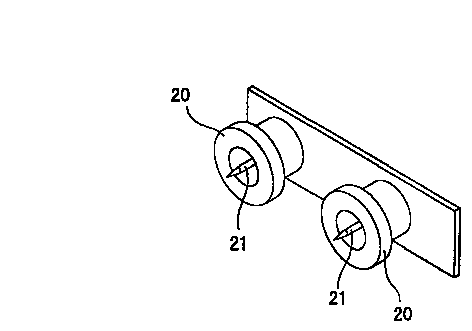
従来、マイナスイオンとオゾンの双方を発生させる装置として、図4に示すように、円筒状金属製電極20と、この円筒電極の中央部に当該円筒電極に対向配置された針電極21とを有し、両電極間に高電圧を印加し、コロナ放電を起こさせるようにしたものが提案されている。
【0004】
この従来装置はマイナスイオンと共に高濃度のオゾンが発生するため、ペット臭、たばこ臭除去などの利用目的には有効である。一方、この従来装置によって、オゾン量の少ないマイナスイオンをも発生させる試みがなされ、例えば、連続運転から間欠運転への変更、円筒電極と針電極との間の対向距離増大などの対応がなされたが、期待される効果を得られるには至っていない。即ち、この従来装置は、ペット臭、たばこ臭などの除去を伴う場合にのみに利用が限定され、上記のような癒し効果を与えるためだけの利用には不向きである。
【0005】
また、特開平6−181087号には、マイナスイオンとオゾンの双方を発生させる他の従来装置として、空間ギャップを介して配置した放電電極及び対向電極と、両電極間に交流電圧を印加する交流高電圧発生回路とを有する電界装置が示されている。この従来装置は、マイナスイオン及びオゾン発生の選択的切り替えのために、印加する交流電圧に関して、マイナスイオン発生のための最適電位と、オゾン発生のための最適電位との切り換えで行うか、または上記の空間ギャップに関して、マイナスイオンを発生させる最適な長さと、オゾンを発生させる最適な長さとの切り換えで行うようにしている。しかし、電位の切り換えで行う場合には、交流高電圧の電圧値をコンデンサで行っており、そのため交流電圧回路が複雑化し、電子部品点数が多くなるという問題があり、またギャップ長さ切り換えで行う場合には、長さ変更のための機械的手段が必要になり、そのため装置が大型化するという問題がある。
【0006】
【発明が解決しようとする課題】
そこで本発明は、ペット臭、たばこ臭などの除去作用と、癒し効果付与作用の双方を一台の装置でもたらし得るようにするために、オゾンを含むマイナスイオンと、オゾンを含まないマイナスイオンとの選択的切り換えを、簡単な装置と簡単な切り換え操作によって行えるようにすることを目的としたものである。
【0007】
【課題を解決するための手段】
上記目的を達成するために、本発明のうち請求項1に記載の発明は、保持体に支持された少なくとも1本の針電極と、同じく前記保持体に支持されたアース電極とを有し、前記針電極とアース電極間に高電圧を印加して針電極尖端部においてコロナ放電を生起させ、このコロナ放電によりオゾンおよびマイナスイオンを発生させる装置において、
前記針電極は、陰極として直流の高電圧が印加されるように接続され、
前記アース電極はその本体部が、前記針電極の軸線に対して直交もしくは略直交する方向へ延び且つ前記針電極に対して一定の間隔をおいて配置された棒状体として形成され、
前記アース電極の前記本体部は、その前記保持体からの距離が前記針電極尖端の前記保持体からの距離と略同様の距離、もしくはそれより大きくなるように選択的に設置されることを特徴とする。
【0008】
前記アース電極本体部の前記保持体からの距離が前記針電極尖端の前記保持体からの距離と略同様である場合には、針電極尖端においてコロナ放電により発生するマイナスイオンは殆どオゾンを含まないものになる。これは、放射されるマイナスイオンが殆どアース電極に衝突することなく装置から飛び出していくことによるものである。一方、前記アース電極本体部の前記保持体からの距離が前記針電極尖端の前記保持体からの距離より大きくなる場合には、放射されるマイナスイオンの一部がアース電極と衝突し、その衝突によってオゾンが発生する。
【0009】
請求項1に記載の発明によれば、オゾンとマイナスイオンの発生比率の変更は、直流高電圧の電圧値、および針電極とアース電極との間の間隔は一定に、上記保持体からアース電極本体部および針電極尖端までの距離、すなわち針電極尖端とアース電極本体部との間の距離を単に変更するだけで達成可能である。
【0010】
請求項2に記載の発明は、上記アース電極が、アース電極本来の作用を果たす中央の本体部と、この本体部に対して略直角に折り曲げて形成された両端の脚部とを有するように略コの字状に形成され、
両端の脚部が保持体に設けたソケットに着脱可能に結合され、
上記の選択的設置が、脚部長さの異なるアース電極を保持体に対して付け替えることによって行われることを特徴とする。
【0011】
請求項2に記載の発明によれば、保持体に対してアース電極を適当なものに差し替えるという簡単な操作で、オゾンとマイナスイオンの発生比率を所望のものに簡単に切り換えられる。
【0012】
請求項3に記載の発明は、上記の選択的設置が、針電極に対してアース電極を針電極軸線方向へ移動させることによって行われることを特徴とする。
【0013】
請求項3に記載の発明によれば、オゾンとマイナスイオンの発生比率の切り換えを、装置外部から摘みなどを操作することによって簡単に行うことができ、微調整も可能となる。
【0014】
請求項4に記載の発明は、一つのアース電極に対して複数の針電極が設けてあることを特徴としている。
【0015】
請求項4に記載の発明によれば、複数の針電極を配置して多量のオゾンおよびマイナスイオンを発生させるようにした装置においても、オゾンとマイナスイオンの発生比率の切り換えは、1つのアース電極の交換または調節を行うだけでよい。
【0016】
【発明の実施の形態】
以下、本発明の実施形態の例を図面に基づいて説明する。
【0017】
図面において、図1は本発明によるオゾンおよびマイナスイオン発生装置の第1の実施形態を示す斜視図であって、図中1は針電極、2はアース電極である。図には2本の並列の針電極と、これら針電極に対向する1つのアース電極が示されている。
【0018】
針電極1は、例えば1〜1.5mm径のまっすぐな金属体であって、基端は保持体としての絶縁性基板3に固定され、反対側の自由端は尖端1aとして形成されている。基板3への針電極の1の固定は、基板3に設けたソケット端子4(図2参照)に針電極の基端を差し込むことによって行われる。ソケット端子4は高圧リード線5を介して高電圧源(図示せず)に接続され、陰極として直流の高電圧が印加される。印加される電圧は、例えばDC−2kV〜5kV程度である。
【0019】
針電極1の下方に所定の間隔(図2の縦方向距離V)を置いて配置されたアース電極2は、例えば1〜1.5mm径のステンレス製の棒を略コの字状に折り曲げて、アース電極本来の作用を行う中央の本体部2aと、この本体部に対して直角に折り曲げて形成される両端の互いに平行な脚部2bとを有するように構成になされている。両端の脚部2aは基板3に設けたソケット端子(例えば、ICソケット)6(図2参照)に差込み、引き抜き可能に、或いは装着、脱着可能に取り付けられ、ソケット端子6はグランド線或いは接地線7に接続されている。
【0020】
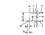
アース電極2の本体部2aは針電極1に対し次のような配置関係をもたらすように決められる。即ち、アース電極本体部2aは、前記針電極1の軸線に対して直交もしくは略直交する方向へ延び且つ前記針電極に対して一定の間隔をおいて配置されている。更に、前記アース電極本体部2aは、前記基板3の基準平面3aからアース電極本体部2aもしくはアース電極本体部軸線までの距離が,基準平面3aから針電極の尖端1aまでの距離と略同様の距離か、それより大きくなるように選択的に設置される。換言すれば、針電極1の軸線方向におけるアース電極本体部2aの位置は、針電極1の尖端1aを含み、針電極1の軸線にほぼ直交し且つ上記基準平面3aに平行な面(図2中、S1)と、前記アース電極2の軸線を含み前記針電極尖端包含面S1に平行な面(図2中、S2)とが一致する場合と、アース電極本体部2aの方が基準平面3aから見て針電極尖端1aより先方へ突出して、両面S1,S2の間に横方向距離Hがもたらされる場合とが選択的にもたらされるように決められる。一致する場合(即ち横方向距離Hがゼロの場合)は、オゾンを殆ど含まないマイナスイオンを発生させるときの位置関係であり、横方向距離Hをもたらす場合はオゾンを含むマイナスイオンを発生させるときの位置関係である。容易に理解され得るように、横方向距離Hの大きさに従って発生するオゾンの量も変化する。
【0021】
一方、針電極1に対するアース電極本体部2aの縦方向距離Vは、上記の横方向距離Hがゼロの場合にオゾンの発生量が最小で、横方向距離Hを変化させたときに、即ちアース電極本体部2aを横方向距離Hが変化する方向へ移動させたときに、オゾン発生量の調整が可能な最適位置を実験により求めている。縦方向距離Vは例えば15〜20mmである。この縦方向距離Vは本実施の形態では固定的であるが、場合によっては変更可能にしてもよい。
【0022】
本実施形態によれば、上記の横方向距離Hの選択、即ちマイナスイオンとオゾンの発生比率の選択は、針電極1を固定的に設けると共に、アース電極2を適合するものに付け替えることによって達成される。しかし、針電極1を取り替えることによっても、発生比率の選択は可能である。針電極1が複数個設けてある場合には、全体の針電極に対して1つの共通のアース電極を交換することで済むので、アース電極交換の方が有利である。
【0023】
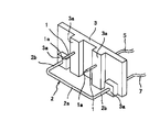
図3に斜視図で示す第2実施形態の場合、第1実施形態の場合と同様の針電極1及びコの字状アース電極2が、それらの基部および脚部2bをインサートモールディングにより樹脂製保持体3内に埋め込むことにより一体的になされ、保持体3を含めて全体的に1つの交換ユニットとして構成されている。この場合、針電極1の基部およびアース電極2の脚部は樹脂製保持体3の反対側面から突出しており、針電極基部からの突出部は高圧リード線5を介して高電圧源(図示せず)に接続され、アース電極脚部からの突出部はグランド線7に接続されている。この実施形態の場合、保持体3の同一平面内にある基準平面3aから針電極1の尖端1aまでの距離と、前記基準平面3aから前記アース電極本体部2aもしくはアース電極本体部軸線までの距離が同様のものと、前記アース電極本体部2aもしくはアース電極本体部軸線までの距離の方が長く、横方向距離Hを有するものとが製作され、更に横方向距離Hが異なるものが数種類製作される。これら各ユニットは、オゾンの発生量が使用目的に適合するように適宜交換される。
【0024】
上記の2つの実施形態にて説明された本発明のオゾンおよびマイナスイオン発生装置は、高電圧発生装置と共に例えばケース内に収容され、更にオゾンおよびマイナスイオン発生装置近傍にファンを設けることにより、例えば空気清浄装置として利用される。
【0025】
【実施例】
上記の実施形態において、針電極1の径が1.5mm、アース電極2の径が1.0mm、縦方向距離Vが16mm、印加直流電圧が−5kVの場合に、横方向距離Hを変化させ針電極尖端1a近傍のオゾン濃度を測定した結果が表1に示され、マイナスイオンの発生量を測定した結果が表2に示されている。また、両結果を線図にて表したものが表3に示されている。
【0026】
【表1】
【表2】
【表3】
上記の測定結果から明らかなように、横方向距離Hがゼロに近いところではオゾンの発生量は少なく、横方向距離Hの値が大きくなるに従いオゾン量は増加する。マイナスイオンの発生量は横方向距離Hの変化にかかわらず略一定である。
【0030】
【発明の効果】
このように本発明によれば、マイナスイオンを発生させて、森林、滝などの自然界と同等のマイナスイオン環境を作り出す場合と、オゾンをも同時に発生させて脱臭効果も得ようとする場合との変更が、針電極とアース電極本体部との間の横方向距離を変えるだけで容易に実現可能となり、例えば住宅や店舗などの各部屋毎に、マイナスイオンのみが必要な場合と、マイナスイオンに加えてオゾンも発生させる場合との使い分けが容易にでき、更にオゾンの発生量も目的に合わせて容易に変更できるなどの効果が得られる。しかも、構造が簡単であるので、製作コストも比較的低くできるという効果も併せて得られる。
【図面の簡単な説明】
【図1】本発明によるオゾンおよびマイナスイオン発生装置の1実施形態を示す概略斜視図である。
【図2】図1の装置の側面図である。
【図3】本発明の他の実施形態を示す概略斜視図である。
【図4】従来のオゾンおよびマイナスイオン発生装置の概略斜視図である。
【符号の説明】
1・・・針電極
1a・・・針電極尖端部
2・・・アース電極
2a・・・アース電極本体部
3・・・保持体
4・・・ソケット端子
5・・・高圧リード線
6・・・ソケット端子
7・・・グランド線
H・・・横方向距離
V・・・縦方向距離[0001]
TECHNICAL FIELD OF THE INVENTION
The present invention relates to a device for generating ozone and negative ions, and more particularly to a device for selectively and efficiently generating both negative ions containing ozone and negative ions containing almost no ozone.
[0002]
[Prior art]
Negative ions stimulate the parasympathetic nerves that work during normal times or when the body and mind are relaxed, giving a healing effect, or increasing the proportion of alpha waves, which are the frequency components of brain waves generated in a relaxed state, to give a healing effect It is known that it has the effect of lowering lactic acid and blood sugar levels and eliminating fatigue, while ozone along with negative ions can smell pets indoors, tobacco in karaoke boxes and coffee shops, and waste odors. It is known that it is effective in deodorizing such as.
[0003]
Conventionally, as a device for generating both negative ions and ozone, as shown in FIG. 4, there is provided a
[0004]
This conventional device generates ozone at a high concentration together with negative ions, and is effective for purposes such as pet odor and tobacco odor removal. On the other hand, with this conventional apparatus, an attempt was made to generate negative ions having a small amount of ozone, and for example, measures such as changing from continuous operation to intermittent operation and increasing the facing distance between the cylindrical electrode and the needle electrode were taken. However, the expected effects have not been achieved. That is, the use of this conventional device is limited only to the case where removal of pet odor, tobacco odor and the like is involved, and is not suitable for use only for providing the above-mentioned healing effect.
[0005]
Japanese Patent Application Laid-Open No. 6-181087 discloses another conventional device for generating both negative ions and ozone, which includes a discharge electrode and a counter electrode disposed through a space gap, and an AC device for applying an AC voltage between the two electrodes. An electric field device having a high voltage generation circuit is shown. In this conventional apparatus, in order to selectively switch between the generation of negative ions and ozone, the alternating voltage to be applied is switched between an optimum potential for generating negative ions and an optimum potential for generating ozone, or The spatial gap is switched between an optimum length for generating negative ions and an optimum length for generating ozone. However, in the case of performing the switching by changing the potential, the voltage value of the AC high voltage is performed by the capacitor. Therefore, there is a problem that the AC voltage circuit is complicated and the number of electronic components increases, and the switching is performed by switching the gap length. In such a case, a mechanical means for changing the length is required, so that there is a problem that the apparatus becomes large.
[0006]
[Problems to be solved by the invention]
Accordingly, the present invention provides an ozone-containing negative ion and an ozone-free negative ion so that both a pet odor and a tobacco odor removing action and a healing effect imparting action can be provided by a single device. The purpose of the present invention is to make it possible to perform selective switching by simple apparatus and simple switching operation.
[0007]
[Means for Solving the Problems]
In order to achieve the above object, the invention according to
The needle electrode is connected such that a high DC voltage is applied as a cathode,
The earth electrode is formed as a rod-shaped body whose main body portion extends in a direction orthogonal or substantially orthogonal to the axis of the needle electrode and is arranged at a constant interval from the needle electrode.
The main body of the ground electrode is selectively installed such that the distance from the holder to the tip of the needle electrode is substantially the same as or larger than the distance from the holder to the tip of the needle electrode. And
[0008]
When the distance of the ground electrode main body from the holder is substantially the same as the distance of the needle electrode tip from the holder, negative ions generated by corona discharge at the needle electrode tip contain almost no ozone. Become something. This is because the emitted negative ions fly out of the device almost without colliding with the ground electrode. On the other hand, when the distance of the ground electrode main body from the holder is larger than the distance of the tip of the needle electrode from the holder, a part of the emitted negative ions collide with the ground electrode, and the collision occurs. Generates ozone.
[0009]
According to the first aspect of the present invention, the generation ratio of ozone and negative ions is changed by changing the voltage value of the DC high voltage and the distance between the needle electrode and the ground electrode from the holder to the ground electrode. This can be achieved simply by changing the distance between the main body and the needle electrode tip, that is, the distance between the needle electrode tip and the ground electrode main body.
[0010]
According to a second aspect of the present invention, the earth electrode has a central main body that functions as an earth electrode and legs at both ends formed by bending the main body substantially at right angles to the main body. It is formed in a substantially U shape,
The legs at both ends are detachably connected to the socket provided on the holder,
The above-mentioned selective installation is characterized in that ground electrodes having different leg lengths are replaced with respect to the holder.
[0011]
According to the second aspect of the present invention, the generation ratio of ozone and negative ions can be easily switched to a desired one by a simple operation of replacing the earth electrode with an appropriate one for the holder.
[0012]
The invention described in
[0013]
According to the third aspect of the present invention, switching of the generation ratio of ozone and negative ions can be easily performed by operating a knob or the like from the outside of the apparatus, and fine adjustment can be performed.
[0014]
The invention described in
[0015]
According to the fourth aspect of the present invention, even in a device in which a plurality of needle electrodes are arranged to generate a large amount of ozone and negative ions, switching of the generation ratio of ozone and negative ions is performed by one earth electrode. All that is required is to exchange or adjust.
[0016]
BEST MODE FOR CARRYING OUT THE INVENTION
Hereinafter, embodiments of the present invention will be described with reference to the drawings.
[0017]
In the drawings, FIG. 1 is a perspective view showing a first embodiment of an ozone and negative ion generator according to the present invention, in which 1 is a needle electrode, and 2 is a ground electrode. The figure shows two parallel needle electrodes and one ground electrode facing these needle electrodes.
[0018]
The
[0019]
The
[0020]
The
[0021]
On the other hand, the vertical distance V of the ground electrode
[0022]
According to the present embodiment, the selection of the above-mentioned lateral distance H, that is, the selection of the generation ratio of negative ions and ozone is achieved by fixedly providing the
[0023]
In the case of the second embodiment shown in a perspective view in FIG. 3, the
[0024]
The ozone and negative ion generator of the present invention described in the above two embodiments is housed in, for example, a case together with the high voltage generator, and further provided with a fan in the vicinity of the ozone and negative ion generator. Used as an air purifier.
[0025]
【Example】
In the above embodiment, when the diameter of the
[0026]
[Table 1]
[Table 2]
[Table 3]
As is clear from the above measurement results, the amount of generated ozone is small where the horizontal distance H is close to zero, and the ozone amount increases as the value of the horizontal distance H increases. The amount of generated negative ions is substantially constant regardless of the change in the horizontal distance H.
[0030]
【The invention's effect】
As described above, according to the present invention, the case where the negative ions are generated to create a negative ion environment equivalent to the natural world such as forests and waterfalls, and the case where the ozone is also generated simultaneously to obtain the deodorizing effect. The change can be easily realized only by changing the lateral distance between the needle electrode and the ground electrode main body.For example, in each room such as a house or a store, when only negative ions are required, there are cases where only negative ions are required. In addition, it is easy to use ozone more easily, and the amount of ozone can be easily changed according to the purpose. In addition, since the structure is simple, the effect that the manufacturing cost can be relatively reduced can be obtained.
[Brief description of the drawings]
FIG. 1 is a schematic perspective view showing one embodiment of an ozone and negative ion generator according to the present invention.
FIG. 2 is a side view of the apparatus of FIG.
FIG. 3 is a schematic perspective view showing another embodiment of the present invention.
FIG. 4 is a schematic perspective view of a conventional ozone and negative ion generator.
[Explanation of symbols]
DESCRIPTION OF
Claims (4)
前記針電極は、陰極として直流の高電圧が印加されるように接続され、
前記アース電極はその本体部が、前記針電極の軸線に対して直交もしくは略直交する方向へ延び且つ前記針電極に対して一定の間隔をおいて配置された棒状体として形成され、
前記アース電極の前記本体部は、その前記保持体からの距離が前記針電極の尖端の前記保持体からの距離と略同様の距離、もしくはそれより大きくなるように選択的に設置される、
ことを特徴とするオゾンおよびマイナスイオン発生装置。At least one needle electrode supported by the holder and an earth electrode also supported by the holder, and a high voltage is applied between the needle electrode and the ground electrode to generate a corona discharge at the tip of the needle electrode. In the device that generates ozone and negative ions by this corona discharge,
The needle electrode is connected such that a high DC voltage is applied as a cathode,
The earth electrode is formed as a rod-shaped body whose main body portion extends in a direction orthogonal or substantially orthogonal to the axis of the needle electrode and is arranged at a constant interval from the needle electrode.
The main body of the ground electrode is selectively installed such that the distance of the needle electrode from the holder is substantially the same as or greater than the distance of the point of the needle electrode from the holder,
An ozone and negative ion generator characterized by the above-mentioned.
両端の脚部が保持体に設けたソケットに着脱可能に結合され、
上記の選択的設置が、脚部長さの異なるアース電極を保持体に対して付け替えることによって行われる、
ことを特徴とする請求項1に記載のオゾンおよびマイナスイオン発生装置。The earth electrode is formed in a substantially U-shape so as to have a central main body part that performs the essential function of the earth electrode, and legs at both ends formed by bending the main body part at substantially right angles,
The legs at both ends are detachably connected to the socket provided on the holder,
The above-mentioned selective installation is performed by replacing a ground electrode having a different leg length with the holder.
The ozone and negative ion generator according to claim 1, characterized in that:
を特徴とする請求項1に記載のオゾンおよびマイナスイオン発生装置。The selective installation is performed by moving the ground electrode relative to the needle electrode in the needle electrode axial direction,
The ozone and negative ion generator according to claim 1, characterized in that:
Priority Applications (1)
| Application Number | Priority Date | Filing Date | Title |
|---|---|---|---|
| JP2002178924A JP2004018348A (en) | 2002-06-19 | 2002-06-19 | Ozone and negative ion generator |
Applications Claiming Priority (1)
| Application Number | Priority Date | Filing Date | Title |
|---|---|---|---|
| JP2002178924A JP2004018348A (en) | 2002-06-19 | 2002-06-19 | Ozone and negative ion generator |
Publications (1)
| Publication Number | Publication Date |
|---|---|
| JP2004018348A true JP2004018348A (en) | 2004-01-22 |
Family
ID=31176505
Family Applications (1)
| Application Number | Title | Priority Date | Filing Date |
|---|---|---|---|
| JP2002178924A Pending JP2004018348A (en) | 2002-06-19 | 2002-06-19 | Ozone and negative ion generator |
Country Status (1)
| Country | Link |
|---|---|
| JP (1) | JP2004018348A (en) |
Cited By (10)
| Publication number | Priority date | Publication date | Assignee | Title |
|---|---|---|---|---|
| JP2006210311A (en) * | 2004-12-28 | 2006-08-10 | Murata Mfg Co Ltd | Ion generation component, ion generation unit, and ion generation device |
| JP2008053000A (en) * | 2006-08-23 | 2008-03-06 | Sharp Corp | Discharge electrode, induction electrode, ion generation element, ion generator, and electric apparatus |
| JP2011018616A (en) * | 2009-07-10 | 2011-01-27 | Sharp Corp | Ion generating element, ion generator, and electric apparatus |
| WO2011092755A1 (en) | 2010-01-26 | 2011-08-04 | Katano Akio | Ion/ozone wind generation device and method |
| CZ303615B6 (en) * | 2011-11-14 | 2013-01-09 | Ceské vysoké ucení technické v Praze Fakulta elektrotechnická | Acoustic resonator combined with electrical discharges |
| JP2013084536A (en) * | 2011-04-06 | 2013-05-09 | Panasonic Corp | Active species emission unit and active species emission device employing the same |
| WO2014184984A1 (en) | 2013-05-13 | 2014-11-20 | 株式会社 片野工業 | Ion/ozone wind generation device and method |
| KR20140135345A (en) * | 2013-05-16 | 2014-11-26 | 한국델파이주식회사 | Ionizer with Unitary Structure and Air Conditioning Apparatus for Vehicle Using the Same |
| KR20170003574A (en) | 2014-05-12 | 2017-01-09 | 가타노 고교 가부시키가이샤 | Ion/ozone wind generation device and method |
| KR20180110078A (en) | 2016-03-30 | 2018-10-08 | 가타노 고교 가부시키가이샤 | Ion wind generator |
-
2002
- 2002-06-19 JP JP2002178924A patent/JP2004018348A/en active Pending
Cited By (15)
| Publication number | Priority date | Publication date | Assignee | Title |
|---|---|---|---|---|
| JP2006210311A (en) * | 2004-12-28 | 2006-08-10 | Murata Mfg Co Ltd | Ion generation component, ion generation unit, and ion generation device |
| JP2008053000A (en) * | 2006-08-23 | 2008-03-06 | Sharp Corp | Discharge electrode, induction electrode, ion generation element, ion generator, and electric apparatus |
| JP2011018616A (en) * | 2009-07-10 | 2011-01-27 | Sharp Corp | Ion generating element, ion generator, and electric apparatus |
| US8373963B2 (en) | 2010-01-26 | 2013-02-12 | Akio Katano | Ion/ozone wind generation device and method |
| WO2011092755A1 (en) | 2010-01-26 | 2011-08-04 | Katano Akio | Ion/ozone wind generation device and method |
| JP2013084536A (en) * | 2011-04-06 | 2013-05-09 | Panasonic Corp | Active species emission unit and active species emission device employing the same |
| CZ303615B6 (en) * | 2011-11-14 | 2013-01-09 | Ceské vysoké ucení technické v Praze Fakulta elektrotechnická | Acoustic resonator combined with electrical discharges |
| WO2014184984A1 (en) | 2013-05-13 | 2014-11-20 | 株式会社 片野工業 | Ion/ozone wind generation device and method |
| KR20160025506A (en) | 2013-05-13 | 2016-03-08 | 가타노 고교 가부시키가이샤 | Ion/ozone wind generation device and method |
| US9620936B2 (en) | 2013-05-13 | 2017-04-11 | Katano Kogyo Co., Ltd. | Ion/ozone wind generation device and method |
| KR20140135345A (en) * | 2013-05-16 | 2014-11-26 | 한국델파이주식회사 | Ionizer with Unitary Structure and Air Conditioning Apparatus for Vehicle Using the Same |
| KR101684363B1 (en) * | 2013-05-16 | 2016-12-08 | 이래오토모티브시스템 주식회사 | Ionizer with Unitary Structure and Air Conditioning Apparatus for Vehicle Using the Same |
| KR20170003574A (en) | 2014-05-12 | 2017-01-09 | 가타노 고교 가부시키가이샤 | Ion/ozone wind generation device and method |
| KR20180110078A (en) | 2016-03-30 | 2018-10-08 | 가타노 고교 가부시키가이샤 | Ion wind generator |
| US10870100B2 (en) | 2016-03-30 | 2020-12-22 | Katano Kogyo Co., Ltd. | Ion wind generation device |
Similar Documents
| Publication | Publication Date | Title |
|---|---|---|
| AU2004244900B2 (en) | Discharge apparatus and air purifying apparatus | |
| JP5000855B2 (en) | Plasma discharge treated water generator, plasma discharge water, plant growth promoting liquid, cosmetic water, industrial ozone cleaning water, medical ozone sterilizing water, and medical ozone treatment water | |
| US7517505B2 (en) | Electro-kinetic air transporter and conditioner devices with 3/2 configuration having driver electrodes | |
| US6585935B1 (en) | Electro-kinetic ion emitting footwear sanitizer | |
| KR101645492B1 (en) | Portable ion generater | |
| KR100901986B1 (en) | Ion generator and method for controlling amount of ozone generated in the same | |
| JP2004018348A (en) | Ozone and negative ion generator | |
| JP2008542998A (en) | Wide area static electricity neutralization apparatus and method | |
| JP2005329236A (en) | Negative ion generator using carbon fiber | |
| CN106969441B (en) | Air conditioner and anion generating device thereof | |
| ATE365390T1 (en) | ION GENERATOR UNIT | |
| KR101117248B1 (en) | ceramic electrode structure for generating ion and ion generation apparatus | |
| JP2002319470A (en) | Ion generation control method, ion generating element, and air conditioner equipped with it | |
| JP4774498B2 (en) | Negative ion generator | |
| JP2005218748A (en) | Discharge device and air purification device | |
| JP2014121424A (en) | Discharge unit and air cleaner using the same | |
| JP2004192993A (en) | Negative ion generating device, manufacturing method and air cleaner thereof, air conditioning equipment | |
| JP3017146B2 (en) | Ozone generator | |
| US20060051259A1 (en) | Ozone generator | |
| JP3028457U (en) | Air purifier | |
| KR101112210B1 (en) | Ion generating drive apparatus using single electrode | |
| JP2004349145A (en) | Ion generator and electric apparatus with ion generator | |
| JP2000082567A (en) | Ozone generator | |
| KR101606798B1 (en) | Ion generator | |
| JP3971643B2 (en) | Negative ion generator |