【0001】
【発明の属する技術分野】
本発明は、小型の概略円筒状でくし歯構造を持つモーターのヨーク部、端子を持ったボビン巻線部を組んだ状態のインサート部品を射出成形用金型内に挿入し、封止成形するための射出成形方法に関するものである。
【0002】
【従来の技術】
端子部を持ったボビン巻線を内包するインサート部品を封止成形する方法としては、ボビン巻線を射出成形時の溶融樹脂の流れ込みで断線しないように、出来るだけ低い射出圧力で成形できる流動性に優れる成形材料を選定するのが普通であるが、樹脂の流動性が優れるため端子部への樹脂漏れによる付着が大きな問題となる。端子部に樹脂が付着した場合、樹脂を取り除く必要があるが、手作業で行なうとリード線を断線させたり、端子部を曲げたりする等のトラブルが発生するとともに当然コストも上がる原因となってしまう。
【0003】
端子部への樹脂付着の対策としては、特開平7−142278号公報に開示されている様に、リード線を被覆材によって被覆し、被覆部を金型でクランプすることにより溶融樹脂がもれることを防止する方法が知られているが、リード線径が0.08mm以下の細線では充分な肉厚の被覆は難しく、この技術を適用することは困難である。
【0004】
また、図6に示すようにリード線部を弾性体33で押さえることにより溶融樹脂の漏れを防止する方法も用いられているが、溶融樹脂の流れを弾性体で直接受けるため、高い射出圧力と高温により弾性体が徐々に破断され、溶融樹脂が端子部にもれることを長期間にわたり防止するのは難しい。またあまり硬い弾性体ではリード線を押しつぶし変形させることもあり、使用できる硬さには限界がある。
【0005】
その他の方法としては、リード線部をエポキシやシリコンーン樹脂で成形前に固める方法もあるが、工程が増えるためコストアップになる。また樹脂を塗布する時に端子部にも付着する危険性がある。
【0006】
【発明が解決しようとする課題】
以上説明したように、ボビン巻線を内包するインサート部品を封止成形する方法において、端子部へ溶融樹脂が漏れることを防止するために、リード線部を弾性体で押さえると、リード線の変形、断線が発生しやすい。また弾性体が溶融樹脂により徐々に破断され、長時間の連続ショットにおいては頻繁に弾性体の交換が必要となる。また破断された弾性体のカスが成形品に混ざり込んでしまうこともある。
【0007】
また、リード線部にシリコーン樹脂などを塗布する方法では工数が増えコストアップになり、また端子部に樹脂が付着するなどの問題がある。
【0008】
従って、本発明は上述した課題に鑑みてなされたものであり、その目的は、ボビン巻線を有する部品をインサート成形する場合に、端子部分に樹脂が回りこむことを防止できるようにすることである。
【0009】
【課題を解決するための手段】
上述した課題を解決し、目的を達成するために、本発明に係わる射出成形方法は、コイルが巻かれたボビンのつば部を延長し、該つば部の端部に接続端子を設け、該接続端子に前記ボビンから引き出された巻き線の端部を接続したインサート部材の周囲に樹脂材料を射出して、該樹脂材料により前記コイルの周囲を覆うための射出成形方法であって、前記ボビンのつば部面上に配置された前記巻き線に対応する金型面に、前記巻線の線径+0.02mm以下の深さの溝を形成した金型を用いて成形を行うことを特徴としている。
【0010】
また、この発明に係わる射出成形方法において、前記金型の前記溝の先端部分の位置に、射出された樹脂材料が前記接続端子に付着するのを防止するための樹脂溜りを形成することを特徴としている。
【0011】
また、この発明に係わる射出成形方法において、前記樹脂溜り内の樹脂材料が前記接続端子に付着するのを防止するために、前記樹脂溜りに隣接した位置で、前記接続端子を挟み込む弾性部材を前記金型に設けることを特徴としている。
【0012】
また、本発明に係わる射出成形方法は、コイルが巻かれたボビンのつば部を延長し、該つば部の端部に接続端子を設け、該接続端子に前記ボビンから引き出された巻き線の端部を接続したインサート部材の周囲に樹脂材料を射出して、該樹脂材料により前記コイルの周囲を覆うための射出成形方法であって、前記ボビンのつば部面上に、前記巻き線を収容するための、前記巻線の線径+0.02mm以下の深さの溝を形成することを特徴としている。
【0013】
【発明の実施の形態】
以下、本発明の好適な一実施形態について説明する。
【0014】
まず、一実施形態の概要について説明する。
【0015】
本実施形態では、ボビン巻線部つば形状の延長上に端子圧入部が形成されたコイルボビンにおいて、巻線部から端子部に接続されたリード線が平面状に形成されたつば面を引き回されている場合、リード線部に相対する金型面にリード線径+0.02mm以下でリード線を潰さない深さ寸法で溝を構成する。このとき、リード線径は0.08mm以下であり、溝深さは0.1mm以下とし、その溝長さはモータ外形寸法部から端子圧入面近傍まで設ける。これにより溶融樹脂は0.1mm以下の溝部に進入しにくくなる。また溝の長さによっては溶融樹脂は溝部の外まで出てこない。また溝部が短く溶融樹脂が漏れてくる場合においては、端子部の圧入部面から端子のプリント基板等の接合部などに、必要個所の下まで漏れてきた溶融樹脂の樹脂溜り空間を形成し、端子必要個所は耐熱性のある弾性材で型締め力を利用して圧縮変形させ保持する。これによりリード線部を直接弾性体で押さえないことによりリード線のつぶれ断線をなくすことが出来る。また溝部から漏れてきた溶融樹脂も樹脂溜り部で樹脂圧が低下し、樹脂温度も下がるため、端子部を保持した弾性体に与えるダメージを最小限にすることが出来る。またリード線が引き回される溝部を金型側でなくボビンつば部側に設けてもよい。
【0016】
以下、一実施形態について具体的に説明する。
【0017】
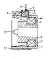
図1は、本発明の一実施形態に係わる封止成形後のコイルを内包したインサート部品の断面図である。
【0018】
図1において、1はくし歯形状10を持つ外側磁極であり、コイル3を挟み込むように内側磁極2が外側磁極1に固定されている。コイル3はボビン4に巻かれておりボビンつば部4aから端子圧入部7が形成されている。リード線5はコイル3からボビンつば部4aの延長上の、端子圧入部7の平面部上面を引き回され端子6の根元に巻き付けられリード線部巻き付け部9を形成している。11は封止樹脂を示す。8は端子6の根元部に設けられた樹脂溜り部に成形時に漏れた樹脂を示す。
【0019】
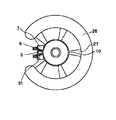
図2は図1に示されるインサート部品をモーターとして組んだ状態を示す図である。
【0020】
図2において、12は軸受け部、13はシャフト、14はマグネットを示す。
【0021】
図3は、図1に示されるインサート部品を成形するための射出成形用金型の一部を示す断面図である。
【0022】
図3において、20は固定側型板を示し、21は可動側型板を示す。射出成形機から射出された溶融樹脂は一次スプール25、ランナー26を介しゲート27を通過してインサート部品が挿入されているキャビティ内に高温、高圧で注入される。19はランナーを突出すエジェクターピンである。22はインサート部品の内側磁極2の内径部をガイドするセンターピンである。23はインサート部品を突出すためのスリーブ、24はくし歯10の内径寸法を決めるための内周駒である。
【0023】
図4は、図3の端子6の近傍を拡大した図である。
【0024】
図4において、コイル3より引き出されたリード線5はボビン4のつば面4aから端子圧入部7の平面上を引き回され、端子圧入部7に圧入された端子6の根元に巻き付けられ、9で示す形状でハンダ付けされている。このとき、固定側型板20のリード線5に相対する部分に溝28が設けられている。
【0025】
本実施形態では、線径0.06mmであり、溝の深さは、線径+0.01mmの0.07mmとした。
【0026】
このとき、封止樹脂(射出される樹脂)としては、成形時の圧力で線径0.06mmのリード線が断線しないように非常に流動性に優れた液晶ポリマーを使用した。実験型に深さ0.07mm、幅0.3mmの溝を設け、この材料で射出圧力50MPa(樹脂圧換算)で成形したところ、流動長は2mmとなった。また0.1mmの溝深さでは流動長は10mmを超えた。
【0027】
本実施形態では、先に述べたように、溝深さ0.07mm、溝幅0.3mm、溝長さは0.5mmであり、溶融樹脂が溝を通過し端子部にまで漏れてくることが予想された。
【0028】
そのため、本実施形態では端子部6の巻線が巻き付けられた根元部9に、体積として0.2mm3の樹脂溜り部8を設けた。この樹脂溜り部8の体積によれば、溝断面積0.07mm×0.3mm=0.021mm2で計算すると、流動長約10mmに相当する樹脂が溜められる。このとき、端子部6を断熱性のある可動側弾性体29、固定側弾性体30で型締めを利用して締め付けることにより、基板などの接合に使う部分への樹脂付着を防止することができる。当然樹脂溜り部8で溶融樹脂圧は低下し、また樹脂温度も低下するため、弾性体29,30へのダメージは極めて小さく抑えられる。。
【0029】
また0.1mmより大きい溝深さでは、溶融樹脂は多量に溝を通過するため、樹脂溜りの容量を越えてしまう危険性がある。
【0030】
図5は他の実施形態の金型を上面から見た図である。ランナー26を通過した溶融樹脂は、くし歯10に対向する位置に設けられたゲート27を介してキャビティに注入される。7は端子圧入部であり、5はリード線、6は端子である。この実施形態では、リード線5に相対する金型面を平面として、端子圧入部7に溝31を設けてリード線5を引き回している。
【0031】
以上説明したように、上記の実施形態では、ボビンつば部からの延長上に端子圧入部、端子を持ったボビン巻線を内包するモーター用インサート部品を射出成形金型内で封止成形する方法において、端子部に射出時に溶融樹脂が付着することを防止するために、ボビンつば部、端子圧入部リード線引き回し部を平面とし、リード線部に対向する金型面にリード線径+0.02mm以下の深さの溝部を設ける。このとき、封止樹脂(射出される樹脂)としてリード線の断線を防止するために流動性に優れた液晶ポリマーなどの材料を選定する必要があるため、溝深さは0.1mmが限界であり、線径としては0.08mm以下の場合に適用される。
【0032】
またその溝幅は、巻線時のバラツキを考慮して決定する。この非常に浅い溝の働きにより射出成形時に溶融樹脂は溝に進入しにくくなり、かつ進入しても急激に冷却されるためその流動長はごくわずかになる。
【0033】
使用樹脂材料、溝の長さによっては溝を通過し端子部まで溶融樹脂が進入することがある。この場合には、端子部の使用しない巻線巻き付け部近傍に進入してくる樹脂材料の量を上回る樹脂溜り部を設け、さらに端子の基板等との接合部に樹脂が付着しないように、耐熱性のある弾性体を用いて、端子使用部を型締め力により弾性体を圧縮変形させて覆い、溶融樹脂の侵入を防ぐ。樹脂溜り部を設けることにより樹脂の圧力は低下し、樹脂温度も下がるために、端子を覆った弾性体を押しのけて溶融樹脂が進入してくることはない。
【0034】
これにより弾性体の溶融樹脂によるダメージを最小にでき、成形ショット数を大幅に伸ばすことが出来る。
【0035】
またリード線部を直接弾性体で押さえることが無いため、リード線のつぶれ、断線をなくすことが出来る。
【0036】
さらに端子圧入部に封止樹脂層が形成されることにより、端子の抜け強度の向上がはかれる。
【0037】
また、他の実施形態では、金型面を平面にし、ボビン側にリード線が引き回される溝形状を設けることにより、同様の効果が得られる。
【0038】
【発明の効果】
以上説明したように、本発明によれば、ボビン巻線を有する部品をインサート成形する場合に、端子部分に樹脂が回りこむことを防止できる。
【図面の簡単な説明】
【図1】本発明の一実施形態に係わる封止成形後のコイルを内包したインサート部品の断面図である。
【図2】図1に示されるインサート部品をモーターに組んだ状態を示す図である。
【図3】図1に示されるインサート部品を成形するための射出成形用金型の一部を示す断面図である。
【図4】図3の端子の近傍を拡大した図である。
【図5】他の実施形態の金型を上面から見た図である。
【図6】従来の金型の断面図である。
【符号の説明】
1 外側磁極
2 内側磁極
3 コイル
4 ボビン
4a ボビンつば部
5 リード線
6 端子
7 端子圧入部
8 樹脂溜り部
9 リード線巻き付け部
10 くし歯
11 封止樹脂
12 軸受け
13 シャフト
14 マグネット
19 エジェクターピン
20 固定側型板
21 可動側型板
22 センターピン
23 スリーブ
24 内周駒
25 スプール
26 ランナー
27 ゲート
28 金型溝
29 可動側弾性体
30 固定側弾性体
31 リード線用溝
32 端子部空間[0001]
TECHNICAL FIELD OF THE INVENTION
According to the present invention, a small yoke portion of a motor having a substantially cylindrical comb-shaped structure and an insert part in a state where a bobbin winding portion having a terminal is assembled are inserted into an injection mold and sealed and molded. And an injection molding method for the same.
[0002]
[Prior art]
As a method of sealing and molding insert parts containing bobbin windings with terminals, the bobbin windings can be molded with the lowest possible injection pressure so that they do not break due to the flow of molten resin during injection molding. It is common to select a molding material that is excellent in resin, but adhesion of the resin to the terminal portion due to leakage of the resin becomes a serious problem because of the excellent fluidity of the resin. If resin adheres to the terminals, it is necessary to remove the resin.However, if it is performed manually, troubles such as breakage of the lead wires and bending of the terminals will occur, and naturally the cost will increase. I will.
[0003]
As a countermeasure against resin adhesion to the terminal portion, as disclosed in JP-A-7-142278, molten resin leaks by coating a lead wire with a coating material and clamping the coating portion with a mold. However, it is difficult to apply a sufficient thickness to a thin wire having a lead wire diameter of 0.08 mm or less, and it is difficult to apply this technique.
[0004]
As shown in FIG. 6, a method of preventing leakage of the molten resin by pressing the lead wire portion with an elastic body 33 is also used. However, since the flow of the molten resin is directly received by the elastic body, a high injection pressure and It is difficult to prevent the elastic body from being gradually broken by the high temperature and the molten resin from leaking to the terminal portion for a long time. In addition, if the elastic body is too hard, the lead wire may be crushed and deformed, and there is a limit to the usable hardness.
[0005]
As another method, there is a method in which the lead wire portion is hardened with epoxy or silicone resin before molding, but the number of steps is increased and the cost is increased. In addition, there is a risk that the resin may adhere to the terminals when the resin is applied.
[0006]
[Problems to be solved by the invention]
As described above, in the method of sealing and molding the insert part including the bobbin winding, in order to prevent the molten resin from leaking to the terminal portion, when the lead wire portion is pressed by an elastic body, the lead wire is deformed. , Disconnection is likely to occur. In addition, the elastic body is gradually broken by the molten resin, and it is necessary to frequently replace the elastic body in a long continuous shot. In addition, the broken elastic body residue may be mixed into the molded product.
[0007]
In addition, the method of applying a silicone resin or the like to the lead wire portion has a problem that the number of steps increases and the cost increases, and that the resin adheres to the terminal portion.
[0008]
Therefore, the present invention has been made in view of the above-described problems, and an object of the present invention is to prevent a resin from flowing around a terminal portion when insert molding a component having a bobbin winding. is there.
[0009]
[Means for Solving the Problems]
In order to solve the above-described problems and achieve the object, an injection molding method according to the present invention extends a collar portion of a bobbin around which a coil is wound, provides a connection terminal at an end of the collar portion, and performs the connection. An injection molding method for injecting a resin material around an insert member connecting an end of a winding drawn out from the bobbin to a terminal and covering the periphery of the coil with the resin material, It is characterized in that molding is performed using a mold in which a groove having a depth equal to or less than the wire diameter of the winding + 0.02 mm is formed on a mold surface corresponding to the winding wire arranged on the flange portion surface. .
[0010]
Further, in the injection molding method according to the present invention, a resin reservoir for preventing the injected resin material from adhering to the connection terminal is formed at a position of a tip portion of the groove of the mold. And
[0011]
Further, in the injection molding method according to the present invention, in order to prevent a resin material in the resin reservoir from adhering to the connection terminal, an elastic member sandwiching the connection terminal at a position adjacent to the resin reservoir is provided. It is characterized by being provided in a mold.
[0012]
In addition, the injection molding method according to the present invention is characterized in that the collar portion of the bobbin around which the coil is wound is extended, a connection terminal is provided at an end of the collar portion, and the connection terminal is provided at the end of the winding drawn out from the bobbin. An injection molding method for injecting a resin material around an insert member connecting the parts and covering the periphery of the coil with the resin material, wherein the winding is accommodated on a flange portion surface of the bobbin. For this purpose, a groove having a depth equal to or less than the wire diameter of the winding + 0.02 mm is formed.
[0013]
BEST MODE FOR CARRYING OUT THE INVENTION
Hereinafter, a preferred embodiment of the present invention will be described.
[0014]
First, an outline of an embodiment will be described.
[0015]
In the present embodiment, in the coil bobbin in which the terminal press-fit portion is formed on the extension of the bobbin winding portion brim shape, the lead wire connected to the terminal portion from the winding portion is routed around the brim surface formed in a planar shape. In this case, a groove is formed on the die surface opposite to the lead wire portion with a lead wire diameter of +0.02 mm or less and a depth dimension that does not crush the lead wire. At this time, the lead wire diameter is 0.08 mm or less, the groove depth is 0.1 mm or less, and the groove length is provided from the outer dimensions of the motor to the vicinity of the terminal press-fitting surface. This makes it difficult for the molten resin to enter the groove of 0.1 mm or less. Further, depending on the length of the groove, the molten resin does not come out of the groove. Also, in the case where the groove portion is short and the molten resin leaks, a resin pool space of the molten resin leaking from the press-fit portion surface of the terminal portion to a joint portion of the terminal printed circuit board or the like to below the required portion is formed, A necessary portion of the terminal is made of a heat-resistant elastic material, and is compressed and deformed using a mold clamping force and held. Thus, the lead wire portion is not directly pressed by the elastic body, so that the lead wire can be prevented from being broken and broken. Further, the molten resin leaked from the groove also reduces the resin pressure in the resin reservoir and lowers the resin temperature, so that damage to the elastic body holding the terminal can be minimized. Further, the groove for leading the lead wire may be provided on the bobbin flange instead of the mold.
[0016]
Hereinafter, one embodiment is specifically described.
[0017]
FIG. 1 is a cross-sectional view of an insert component including a coil after sealing and molding according to an embodiment of the present invention.
[0018]
In FIG. 1, reference numeral 1 denotes an outer magnetic pole having a comb tooth shape 10, and an inner magnetic pole 2 is fixed to the outer magnetic pole 1 so as to sandwich the coil 3. The coil 3 is wound around a bobbin 4, and a terminal press-fitting portion 7 is formed from the bobbin flange 4a. The lead wire 5 is routed from the coil 3 on the flat upper surface of the terminal press-fitting portion 7 on the extension of the bobbin flange portion 4a and wound around the root of the terminal 6 to form a lead wire winding portion 9. Reference numeral 11 denotes a sealing resin. Reference numeral 8 denotes a resin leaked during molding in a resin reservoir provided at the base of the terminal 6.
[0019]
FIG. 2 is a view showing a state where the insert parts shown in FIG. 1 are assembled as a motor.
[0020]
In FIG. 2, reference numeral 12 denotes a bearing, 13 denotes a shaft, and 14 denotes a magnet.
[0021]
FIG. 3 is a sectional view showing a part of an injection molding die for molding the insert part shown in FIG.
[0022]
In FIG. 3, reference numeral 20 denotes a fixed-side template, and 21 denotes a movable-side template. The molten resin injected from the injection molding machine passes through a gate 27 via a primary spool 25 and a runner 26 and is injected at a high temperature and a high pressure into a cavity in which an insert component is inserted. 19 is an ejector pin for projecting the runner. Reference numeral 22 denotes a center pin for guiding the inner diameter of the inner magnetic pole 2 of the insert part. Reference numeral 23 denotes a sleeve for projecting the insert part, and reference numeral 24 denotes an inner peripheral piece for determining the inner diameter of the comb tooth 10.
[0023]
FIG. 4 is an enlarged view of the vicinity of the terminal 6 in FIG.
[0024]
In FIG. 4, the lead wire 5 drawn out from the coil 3 is routed from the flange surface 4a of the bobbin 4 on the plane of the terminal press-fitting portion 7, and is wound around the base of the terminal 6 press-fitted into the terminal press-fit portion 7. It is soldered in the shape shown by. At this time, a groove 28 is provided in a portion of the fixed side template 20 facing the lead wire 5.
[0025]
In the present embodiment, the wire diameter is 0.06 mm, and the depth of the groove is 0.07 mm, which is (wire diameter + 0.01 mm).
[0026]
At this time, as a sealing resin (resin to be injected), a liquid crystal polymer having an extremely excellent fluidity was used so that a lead wire having a wire diameter of 0.06 mm was not broken by a pressure during molding. When a groove having a depth of 0.07 mm and a width of 0.3 mm was provided in the experimental mold, and the material was molded at an injection pressure of 50 MPa (converted to resin pressure), the flow length was 2 mm. At a groove depth of 0.1 mm, the flow length exceeded 10 mm.
[0027]
In the present embodiment, as described above, the groove depth is 0.07 mm, the groove width is 0.3 mm, and the groove length is 0.5 mm, and the molten resin passes through the groove and leaks to the terminal portion. Was expected.
[0028]
Therefore, in the present embodiment, the resin reservoir 8 having a volume of 0.2 mm 3 is provided at the base 9 around which the winding of the terminal 6 is wound. According to the volume of the resin reservoir 8, a resin corresponding to a flow length of about 10 mm is stored when the groove sectional area is calculated as 0.07 mm × 0.3 mm = 0.021 mm 2 . At this time, by adhering the terminal portion 6 with the movable-side elastic body 29 and the fixed-side elastic body 30 having heat insulation by using mold clamping, it is possible to prevent resin from adhering to a portion used for bonding such as a substrate. . Naturally, the molten resin pressure is reduced in the resin reservoir 8 and the resin temperature is also reduced, so that damage to the elastic bodies 29 and 30 can be suppressed to a very small level. .
[0029]
If the groove depth is larger than 0.1 mm, a large amount of the molten resin passes through the groove, and there is a risk of exceeding the capacity of the resin reservoir.
[0030]
FIG. 5 is a diagram of a mold according to another embodiment as viewed from above. The molten resin that has passed through the runner 26 is injected into the cavity via a gate 27 provided at a position facing the comb teeth 10. Reference numeral 7 denotes a terminal press-fit portion, reference numeral 5 denotes a lead wire, and reference numeral 6 denotes a terminal. In this embodiment, the lead wire 5 is routed by providing a groove 31 in the terminal press-fitting portion 7 with the mold surface facing the lead wire 5 as a plane.
[0031]
As described above, in the above-described embodiment, a method for sealingly molding a motor insert component including a bobbin winding having a terminal press-fit portion and a terminal on an extension from a bobbin flange portion in an injection molding die. In order to prevent the molten resin from adhering to the terminal portion during injection, the bobbin flange portion, the terminal press-fitting portion and the lead wire routing portion are made flat, and the mold surface facing the lead wire portion has a lead wire diameter of +0.02 mm. A groove having the following depth is provided. At this time, since it is necessary to select a material such as a liquid crystal polymer having excellent fluidity as a sealing resin (a resin to be injected) in order to prevent disconnection of the lead wire, the groove depth is limited to 0.1 mm. Yes, it is applied when the wire diameter is 0.08 mm or less.
[0032]
The groove width is determined in consideration of variations at the time of winding. The function of this very shallow groove makes it difficult for the molten resin to enter the groove during injection molding, and even when it enters, the molten resin is rapidly cooled, so that its flow length is very small.
[0033]
Depending on the resin material used and the length of the groove, the molten resin may pass through the groove and enter the terminal. In this case, provide a resin reservoir that exceeds the amount of the resin material entering the vicinity of the unused portion of the winding around the terminal portion. Using a flexible elastic body, the terminal use portion is covered by compressing and deforming the elastic body by a mold clamping force to prevent intrusion of molten resin. By providing the resin reservoir, the pressure of the resin is reduced and the temperature of the resin is also reduced, so that the molten resin does not enter the terminal by pushing the elastic body covering the terminals.
[0034]
Thereby, the damage of the elastic body due to the molten resin can be minimized, and the number of molding shots can be greatly increased.
[0035]
Further, since the lead wire portion is not directly pressed by the elastic body, the lead wire can be prevented from being broken or broken.
[0036]
Further, by forming the sealing resin layer in the terminal press-fitting portion, it is possible to improve the terminal pull-out strength.
[0037]
In another embodiment, the same effect can be obtained by making the mold surface flat and providing a groove shape on the bobbin side where the lead wire is routed.
[0038]
【The invention's effect】
As described above, according to the present invention, when a component having a bobbin winding is insert-molded, it is possible to prevent the resin from flowing around the terminal portion.
[Brief description of the drawings]
FIG. 1 is a cross-sectional view of an insert component including a coil after sealing and molding according to an embodiment of the present invention.
FIG. 2 is a view showing a state where the insert part shown in FIG. 1 is assembled to a motor.
FIG. 3 is a sectional view showing a part of an injection mold for molding the insert part shown in FIG. 1;
FIG. 4 is an enlarged view of the vicinity of a terminal in FIG. 3;
FIG. 5 is a view of a mold according to another embodiment as viewed from above.
FIG. 6 is a sectional view of a conventional mold.
[Explanation of symbols]
REFERENCE SIGNS LIST 1 outer magnetic pole 2 inner magnetic pole 3 coil 4 bobbin 4a bobbin flange 5 lead wire 6 terminal 7 terminal press-fitting portion 8 resin reservoir 9 lead wire winding portion 10 comb tooth 11 sealing resin 12 bearing 13 shaft 14 magnet 19 ejector pin 20 fixed Side template 21 Movable template 22 Center pin 23 Sleeve 24 Inner circumference piece 25 Spool 26 Runner 27 Gate 28 Mold groove 29 Movable elastic body 30 Fixed elastic body 31 Lead wire groove 32 Terminal space