JP2004016341A - Mattress device - Google Patents
Mattress device Download PDFInfo
- Publication number
- JP2004016341A JP2004016341A JP2002172806A JP2002172806A JP2004016341A JP 2004016341 A JP2004016341 A JP 2004016341A JP 2002172806 A JP2002172806 A JP 2002172806A JP 2002172806 A JP2002172806 A JP 2002172806A JP 2004016341 A JP2004016341 A JP 2004016341A
- Authority
- JP
- Japan
- Prior art keywords
- spring structure
- elastic
- elastic body
- elastic member
- mattress device
- Prior art date
- Legal status (The legal status is an assumption and is not a legal conclusion. Google has not performed a legal analysis and makes no representation as to the accuracy of the status listed.)
- Pending
Links
Images


Abstract
Description
【0001】
【発明の属する技術分野】
この発明は周辺部を硬くして実効使用面積の拡大を図るようにしたマットレス装置に関する。
【0002】
【従来の技術】
一般に、マットレス装置はスプリング構体を有し、このスプリング構体の上下面に平板状の弾性材を積層し、この積層体を、布地を袋状に縫製した外装体によって被覆して構成されている。
【0003】
上記スプリング構体は、複数のコイル状のばねを行列状に配置し、隣り合うばねの上端面及び下端面をそれぞれヘリカル線で連結して形成されている。また、ばねとしては、1本の線材によって複数のコイル部が軸線をほぼ平行にして連続して形成された、いわゆる連続ばねが用いられることがあり、その場合、複数の連続ばねを並設し、隣り合う連続ばねのコイル部の上端と下端とをヘリカル線によって連結して形成されたものもある。
【0004】
いずれの構成のスプリング構体を用いた場合でも、スプリング構体は、ばね相互の連結度合が少ない周辺部が他の部分に比べて柔らかくなるため、周辺部を有効に使用することができず、マットレス装置の実効使用面積が小さくなるということがあった。
【0005】
スプリング構体の実効使用面積の拡大を図るため、本件出願人は特開昭49−120772号公報に示されるマットレス装置を提案した。この公報に示されたマットレス装置は、外周面に遮蔽シートが設けられたスプリング構体を金型内に収容し、このスプリング構体の外周面に弾性体を発泡成形する。それによって、この弾性体により上記スプリング構体の周辺部、つまりマットレス装置の周辺部を補強するようにしている。
【0006】
【発明が解決しようとする課題】
スプリング構体の外周面に弾性体を発泡成形するには、上記金型をスプリング構体が収容できる大きさにしなければならない。そのため、大きな金型が必要となり、コストアップを招くということがある。しかも、弾性体を発泡成形するためには発泡成形作業を伴うから、生産性が低下するということがある。
【0007】
一方、最近ではマットレス装置のリサイクルが要望されている。マットレス装置をリサイクルするためには、金属部分、合成樹脂部分、布地部分等、マットレス装置を使用されている材料ごとに分けることが必要となる。
【0008】
しかしながら、スプリング構体の外周面に弾性体を発泡成形すると、リサイクル時に上記弾性体をスプリング構体から剥離する作業に多くの手間が掛かるから、リサイクルに不向きである。
【0009】
この発明は、スプリング構体の周縁部の補強を容易に行うことができるようにしたマットレス装置を提供することにある。
【0010】
【課題を解決するための手段】
請求項1の発明は、コイル部を有するばねによって形成されたスプリング構体と、
このスプリング構体の外周面に設けられた第1の弾性材と、
この第1の弾性材の内周面に設けられ上記スプリング構体の周辺部に位置するコイル部のピッチ間に入り込んだ補強凸部と、
上記スプリング構体と第1の弾性材とがなす上面と下面とに設けられた第2の弾性材と、
上記第1、第2の弾性材を被覆した外装体と、
を具備したことを特徴とするマットレス装置にある。
【0011】
請求項2の発明は、上記スプリング構体の上下面の周縁部には枠線が設けられ、上記第1の弾性材の上面と下面とには上記枠線が入り込む凹部が設けられていることを特徴とする請求項1記載のマットレス装置にある。
【0012】
請求項3の発明は、上記第2の弾性材の周辺部は、上記第1の弾性材の上面と下面とに接着固定され、上記第1の弾性材には、この第1の弾性材の内面と外面とに貫通した通気孔が形成されていることを特徴とする請求項1記載のマットレス装置にある。
【0013】
請求項4の発明は、上記第2の弾性材の周辺部は、上記第1の弾性材の上面と下面とに接着固定され、これら第1の弾性材と第2の弾性材との接着面には一端部が上記外装体に固定されたフランジ布の他端部が一体的に接着固定されていることを特徴とする請求項1記載のマットレス装置にある。
【0014】
請求項5の発明は、上記第1の弾性体と上記補強凸部とは、上記スプリング構体の厚さ方向に対して硬さを変化させたことを特徴とする請求項1記載のマットレス装置にある。
【0015】
この発明によれば、スプリング構体の周辺部に設けられた第1の弾性材の内周面に補強凸部を設け、この補強凸部をスプリング構体の周辺部に位置するコイル部のピッチ間に入り込ませたから、この補強凸部によって上記コイル部が補強され、スプリング構体の周辺部を硬くすることができる。
【0016】
【発明の実施の形態】
以下、図面を参照しながらこの発明の一実施の形態を説明する。
【0017】
図1乃至図3に示すこの発明のマットレス装置はスプリング構体1を備えている。このスプリング構体1は複数のばね2によって形成されている。このばね2は、1本の線材によって軸線をほぼ平行にして所定間隔で離間した複数のコイル部3を有し、隣り合うコイル部3の上端と下端とはそれぞれ上部連結杆4と下部連結杆5とによって連結されている。なお、ばね2は、隣り合うコイル部3の中途部を互いに絡み合わせている。
【0018】
上記スプリング構体1は複数の上記ばね2を並設し、並設されたばね2のコイル部3の上面と下面とを、それぞれヘリカル線6によって連結して構成されている。それによって、スプリング構体1は所定の厚さを有する矩形板状をなしていて、その上下面の周縁部にはそれぞれ枠線7がクリップ8によって取着されている。
【0019】
上記スプリング構体1の外周面には、比較的硬いウレタンフォームなどによって形成された第1の弾性体11が全周にわたって設けられている。この実施の形態では、軟質ウレタンフォームを粉砕したチップを主原料として、これにウレタン接着剤を混合してプレス成形したクッション材を使用しており、その硬さはプレス圧の調整により行なっている。
【0020】
上記第1の弾性体11は断面矩形状の角柱状であって、高さ寸法は上記スプリング構体1の高さ寸法よりもわずかに大きく設定されている。この第1の弾性体11はスプリング構体1の各辺に対応する長さの4つの部分に分割形成され、両端面は45度の角度の傾斜面に形成されている。
【0021】
上記第1の弾性体11の内周面には、補強部材15が一側面を接着固定して設けられている。この補強部材15の他側面には、断面三角形状をなした複数、この実施の形態では3つの補強凸部12が上下方向に所定間隔で設けられている。
【0022】
上記補強部材15は第1の弾性体11と同様、4つの部分に分割され、分割された各部分の長手方向の両端面は45度の斜面に形成されている。
【0023】
そして、内面に補強部材15が設けられた4つの第1の弾性体11は、それぞれスプリング構体1の外周面に設けられ、隣り合う長手方向両端面を乾燥時に硬化する接着剤によって接着固定して設けられている。
【0024】
第1の弾性体11の上面と下面とには、それぞれ内周面に開放した凹部13が形成され、さらに第1の弾性体11には、その内周面と外周面とを連通する複数の通気孔14が穿設されている。
【0025】
そして、第1の弾性体11は、内周面に設けられた補強凸部12をスプリング構体1の周辺部に位置するコイル部3のピッチ間に嵌め込み、上面と下面に形成された凹部13に上下面の周縁部に設けられた枠線7を嵌め込んで上記スプリング構体11の周辺部に設けられている。
【0026】
上記補強凸部12はコイル部3のピッチ間の断面形状よりもわずかに大きく形成されている。それによって、補強凸部12をコイル部3のピッチ間にはめ込むと、この補強凸部12が弾性的に圧縮変形し、コイル部3を形成する線材に弾性的に密着するから、コイル部3が補強凸部12によって確実に補強される。
【0027】
なお、上記補強凸部12は第1の弾性体11と別体に形成して接着固定したが、第1の弾性体11と一体成形してもよい。
【0028】
図1と図2に示すように、上記スプリング構体1の上面と下面とには、比較的硬質のフェルトによってスプリング構体1の上下面とほぼ同じ大きさに形成された第1の保護シート16が積層されている。この第1の保護シート16には、上記スプリング構体1の上下面と第1の弾性体11の上下面とがなす面積とほぼ同じ大きさに形成された第2の保護シート17が積層されている。この第2の保護シート17は上記第1の保護シート16よりも柔らかなフェルトによって形成されている。
【0029】
上記第2の保護シート17には低反発ウレタンフォームによってこの第2の保護シート17とほぼ同じ大きさの矩形板状に形成された第2の弾性体18が積層されている。上下一対の第2の弾性体18の内面周辺部は、上記第2の保護シート17を介して上記第1の弾性体11の上面と下面とにそれぞれ接着固定されている。
【0030】
第2の弾性体18と第1の弾性体11とを接着固定する前に、図2に示すように、第1の弾性体11の上面に周方向に所定間隔で複数の帯状のフランジ布19の一端部を接着剤によって仮止めしておく。そして、第1の弾性体11の上面に第2の保護シート17を介して上記第2の弾性体18を接着固定すると、上記フランジ布19の一端部が一体的に固定される。
【0031】
上記第1の弾性体11の外周面と、上記第2の弾性体18の外面とは外装体21によって被覆されている。この外装体21は、第1の弾性体11の外周面を被覆したまち地22と、上記第2の弾性体18の外面を被覆した一対の鏡地23とからなる。まち地22の上下端部は、一対の鏡地23の周辺部にテープ24によって縫合され、この縫合部分に上記フランジ布19の他端部が一体に縫合されている。
【0032】
それによって、外装体21はフランジ布19を介してスプリング構体1に保持されるため、スプリング構体1に対してずれ動くのが防止されている。
【0033】
なお、上記鏡地23は表地25と裏地26との間に薄いウレタンフォームなどの弾性シート27を設け、これら三者を一体的にキルティングして形成されている。
【0034】
このように構成されたマットレス装置によれば、スプリング構体1の周辺部に設けられる第1の弾性体11の内周面に、スプリング構体1の周辺部に位置するばね2のコイル部3のピッチ間に弾性的に密着状態で入り込む補強凸部12を設けるようにした。
【0035】
そのため、スプリング構体1の周辺部に位置するコイル部3は、上記補強凸部12によって補強されるから、その周辺部を他の部分とほぼ同じ硬さにして使用することが可能となる。つまり、マットレス装置の周辺部を有効に使用することができるから、このマットレス装置の実効使用面積を拡大することができる。
【0036】
スプリング構体1の周辺部に設けられた第1の弾性体11の上下面には、スプリング構体1の上下面に設けられた第2の弾性体18の内面の周辺部が接着固定されている。つまり、第1の弾性体11と第2の弾性体18とは一体化されている。
【0037】
そのため、スプリング構体1が荷重を受けて圧縮変形しても、上記第1の弾性体11がスプリング構体1の周辺部から外れることがないから、第1の弾性体11の内面に設けられた補強凸部12がコイル部3のピッチ間から外れることもない。したがって、上記補強凸部12によるスプリング構体1の周辺部に位置するコイル部3の補強状態を確実に維持することができる。
【0038】
内周面に補強部材15が接着固定された第1の弾性体11は、補強部材15とともに4つの部分に分割され、45度の傾斜面に形成された長手方向の両端面を乾燥時に硬化する接着剤によって接着固定してスプリング構体1の外周面に設けられている。
【0039】
そのため、スプリング構体1の周辺部は、第1の弾性体11と補強部材15とによって補強され、しかも4つの部分に分割された第1の弾性体11と補強部材15とを接着固定した接着剤の硬さによっても補強されるから、スプリング構体1の横揺れを防止することができる。
【0040】
上記第1の弾性体11は、上下面が第2の弾性体18の内面周辺部に接着固定されているが、スプリング構体1に対しては内面に設けられた補強凸部12をコイル部3に挟んでいるだけである。
【0041】
そのため、第1の弾性体11は、第2の弾性体18との接着箇所を剥離すれば、スプリング構体1と簡単に分離することができるから、リサイクル時にマットレス装置を材料ごとに分ける作業が容易となる。
【0042】
上記第1の弾性体11には、この内面と外面とを貫通する通気孔14が形成されている。そのため、第1の弾性体11の上下面に、第2の弾性体18の内面周辺部を接着固定しても、これら弾性体11,18によって形成された空間部、つまりスプリング構体1が密閉されることがないから、荷重を受けたスプリング構体1は円滑に弾性変形するとともに、内部に湿気がこもってスプリング構体1が早期に発錆するのを防止できる。
【0043】
上記第1の弾性体11の上面と、第2の弾性体18の内面周辺部との接着箇所にフランジ布19の一端部を挟み込み、この他端部を外装体21に縫合した。そのため、上記外装体21がスプリング構体1に対してずれ動くことがないから、マットレス装置の外観形状や性能を良好に維持することができる。
【0044】
第1の弾性体11の上下面には、内周面側に開放した凹部13を形成し、この凹部13にスプリング構体1の上下面の周縁部に設けられた枠線7を位置させるようにした。
【0045】
そのため、上記枠線7が第1の弾性体11の上下面に突出することがないから、上記枠線7の硬さがマットレス装置に仰臥した利用者に伝わり難くなり、寝心地を損なうのを防止できる。
【0046】
この発明は上記一実施の形態に限定されるものでなく、たとえばスプリング構体はコイルスプリングを行列状に配置して構成したものであってもよく、要はコイル部を有するばねによって形成されていればよい。
【0047】
上記第1の弾性体と補強凸部を形成する補強部材とを、スプリング構体の厚さ方向に対して複数に分割し、分割されたそれぞれを硬さの異なる弾性材料で形成し、接着固定するようにしてもよい。それによって、スプリング構体の上下いずれの面を利用するかによって、利用者に与える使用感覚を変えることができる。
【0048】
【発明の効果】
以上のようにこの発明によれば、スプリング構体の周辺部に設けられた第1の弾性材の内周面に補強凸部を設け、この補強凸部をスプリング構体の周辺部に位置するコイル部のピッチ間に入り込ませるようにした。
【0049】
そのため、上記補強凸部によってスプリング構体の周辺部に位置するコイル部を補強できるから、マットレス装置の実行使用面積を拡大することができる。
【図面の簡単な説明】
【図1】この発明の一実施の形態に係るマットレス装置の一部分を示す断面図。
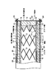
【図2】マットレス装置の一部を破断して内部を示した斜視図。
【図3】ばねと第1の弾性体との一部分を示す斜視図。
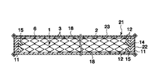
【図4】マットレス装置全体の断面図。
【符号の説明】
1…スプリング構体
2…ばね
3…コイル部
7…枠線
11…第1の弾性体
12…補強凸部
13…凹部
14…通気孔
18…第2の弾性体
21…外装体[0001]
TECHNICAL FIELD OF THE INVENTION
BACKGROUND OF THE
[0002]
[Prior art]
In general, a mattress device has a spring structure, and a flat elastic material is laminated on the upper and lower surfaces of the spring structure, and the laminated body is covered with an exterior body obtained by sewing a fabric into a bag shape.
[0003]
The spring assembly is formed by arranging a plurality of coiled springs in a matrix and connecting the upper end surface and the lower end surface of adjacent springs with helical lines. Further, as the spring, a so-called continuous spring in which a plurality of coil portions are continuously formed with a single wire rod with their axes substantially parallel to each other may be used. In this case, a plurality of continuous springs are arranged in parallel. There is also one formed by connecting the upper end and the lower end of a coil portion of an adjacent continuous spring by a helical wire.
[0004]
Regardless of the configuration of the spring structure used, the periphery of the spring structure, in which the degree of connection between the springs is small, is softer than the other parts, and the periphery cannot be used effectively. May have a reduced effective use area.
[0005]
In order to increase the effective use area of the spring structure, the present applicant has proposed a mattress device disclosed in Japanese Patent Application Laid-Open No. 49-120772. In the mattress device disclosed in this publication, a spring structure provided with a shielding sheet on an outer peripheral surface is housed in a mold, and an elastic body is foam-formed on the outer peripheral surface of the spring structure. Thereby, the periphery of the spring structure, that is, the periphery of the mattress device is reinforced by the elastic body.
[0006]
[Problems to be solved by the invention]
In order to foam the elastic body on the outer peripheral surface of the spring structure, the mold must be large enough to accommodate the spring structure. For this reason, a large mold is required, which may lead to an increase in cost. In addition, since foam molding of the elastic body involves a foam molding operation, productivity may be reduced.
[0007]
On the other hand, recently, there is a demand for recycling of the mattress device. In order to recycle the mattress device, it is necessary to separate the mattress device for each material used, such as a metal portion, a synthetic resin portion, and a fabric portion.
[0008]
However, if the elastic body is foam-molded on the outer peripheral surface of the spring structure, it takes much time and effort to separate the elastic body from the spring structure at the time of recycling, which is not suitable for recycling.
[0009]
SUMMARY OF THE INVENTION It is an object of the present invention to provide a mattress device which can easily reinforce a peripheral portion of a spring structure.
[0010]
[Means for Solving the Problems]
The invention according to
A first elastic member provided on an outer peripheral surface of the spring structure;
A reinforcing projection provided on the inner peripheral surface of the first elastic member and entering between the pitches of the coil portions located at the periphery of the spring structure;
A second elastic member provided on an upper surface and a lower surface formed by the spring structure and the first elastic member;
An exterior body coated with the first and second elastic members,
A mattress device comprising:
[0011]
According to a second aspect of the present invention, a frame line is provided at a peripheral portion of upper and lower surfaces of the spring structure, and a concave portion into which the frame line enters is provided at an upper surface and a lower surface of the first elastic member. The mattress device according to
[0012]
According to a third aspect of the present invention, the peripheral portion of the second elastic member is bonded and fixed to an upper surface and a lower surface of the first elastic member, and the first elastic member is provided with the first elastic member. 2. The mattress device according to
[0013]
According to a fourth aspect of the present invention, the peripheral portion of the second elastic member is adhered and fixed to an upper surface and a lower surface of the first elastic member, and a bonding surface between the first elastic member and the second elastic member. 2. The mattress device according to
[0014]
According to a fifth aspect of the present invention, in the mattress device according to the first aspect, the first elastic body and the reinforcing protrusion have different hardnesses in a thickness direction of the spring structure. is there.
[0015]
According to the present invention, the reinforcing protrusion is provided on the inner peripheral surface of the first elastic member provided on the peripheral portion of the spring structure, and the reinforcing protrusion is provided between the pitches of the coil portions located on the peripheral portion of the spring structure. Since the coil portion is inserted, the coil portion is reinforced by the reinforcing protrusion, and the peripheral portion of the spring structure can be hardened.
[0016]
BEST MODE FOR CARRYING OUT THE INVENTION
Hereinafter, an embodiment of the present invention will be described with reference to the drawings.
[0017]
The mattress device of the present invention shown in FIGS. 1 to 3 includes a
[0018]
The
[0019]
On the outer peripheral surface of the
[0020]
The first
[0021]
On the inner peripheral surface of the first
[0022]
The reinforcing
[0023]
The four first
[0024]
The upper surface and the lower surface of the first
[0025]
Then, the first
[0026]
The reinforcing
[0027]
The reinforcing
[0028]
As shown in FIGS. 1 and 2, a first
[0029]
On the second
[0030]
Before the second
[0031]
The outer peripheral surface of the first
[0032]
As a result, the
[0033]
The
[0034]
According to the mattress device configured as described above, the pitch of the
[0035]
Therefore, since the
[0036]
A peripheral portion of an inner surface of a second
[0037]
For this reason, even if the
[0038]
The first
[0039]
Therefore, the peripheral portion of the
[0040]
The upper and lower surfaces of the first
[0041]
Therefore, the first
[0042]
The first
[0043]
One end of the
[0044]
On the upper and lower surfaces of the first
[0045]
Therefore, since the
[0046]
The present invention is not limited to the above-described embodiment. For example, the spring structure may be configured by arranging coil springs in a matrix, and in other words, the spring structure may be formed by a spring having a coil portion. Just fine.
[0047]
The first elastic body and the reinforcing member forming the reinforcing projection are divided into a plurality of parts in the thickness direction of the spring structure, and each of the divided parts is formed of an elastic material having a different hardness, and is adhesively fixed. You may do so. This makes it possible to change the feeling of use given to the user depending on whether the upper or lower surface of the spring structure is used.
[0048]
【The invention's effect】
As described above, according to the present invention, the reinforcing protrusion is provided on the inner peripheral surface of the first elastic member provided on the peripheral portion of the spring structure, and the reinforcing protrusion is located on the peripheral portion of the spring structure. Between the pitches.
[0049]
Therefore, the coil portion located in the peripheral portion of the spring structure can be reinforced by the reinforcing protrusion, so that the effective use area of the mattress device can be increased.
[Brief description of the drawings]
FIG. 1 is a sectional view showing a part of a mattress device according to an embodiment of the present invention.
FIG. 2 is a perspective view showing the inside of the mattress device with a part broken away.
FIG. 3 is a perspective view showing a part of a spring and a first elastic body.
FIG. 4 is a cross-sectional view of the entire mattress device.
[Explanation of symbols]
DESCRIPTION OF
Claims (5)
このスプリング構体の外周面に設けられた第1の弾性材と、
この第1の弾性材の内周面に設けられ上記スプリング構体の周辺部に位置するコイル部のピッチ間に入り込んだ補強凸部と、
上記スプリング構体と第1の弾性材とがなす上面と下面とに設けられた第2の弾性材と、
上記第1、第2の弾性材を被覆した外装体と、
を具備したことを特徴とするマットレス装置。A spring structure formed by a spring having a coil portion;
A first elastic member provided on an outer peripheral surface of the spring structure;
A reinforcing projection provided on the inner peripheral surface of the first elastic member and entering between the pitches of the coil portions located at the periphery of the spring structure;
A second elastic member provided on an upper surface and a lower surface formed by the spring structure and the first elastic member;
An exterior body coated with the first and second elastic members,
A mattress device comprising:
Priority Applications (1)
| Application Number | Priority Date | Filing Date | Title |
|---|---|---|---|
| JP2002172806A JP2004016341A (en) | 2002-06-13 | 2002-06-13 | Mattress device |
Applications Claiming Priority (1)
| Application Number | Priority Date | Filing Date | Title |
|---|---|---|---|
| JP2002172806A JP2004016341A (en) | 2002-06-13 | 2002-06-13 | Mattress device |
Publications (1)
| Publication Number | Publication Date |
|---|---|
| JP2004016341A true JP2004016341A (en) | 2004-01-22 |
Family
ID=31172266
Family Applications (1)
| Application Number | Title | Priority Date | Filing Date |
|---|---|---|---|
| JP2002172806A Pending JP2004016341A (en) | 2002-06-13 | 2002-06-13 | Mattress device |
Country Status (1)
| Country | Link |
|---|---|
| JP (1) | JP2004016341A (en) |
Cited By (6)
| Publication number | Priority date | Publication date | Assignee | Title |
|---|---|---|---|---|
| KR20050043593A (en) * | 2004-04-16 | 2005-05-11 | 이헌수 | Spring assembly of mattress |
| JP2008307120A (en) * | 2007-06-12 | 2008-12-25 | France Bed Co Ltd | Mattress device and method of recycling mattress device |
| KR101559748B1 (en) * | 2008-01-18 | 2015-10-13 | 실리 테크놀로지 엘엘씨 | Innerspring dampening inserts |
| JP2017072338A (en) * | 2015-10-09 | 2017-04-13 | 星朋商工株式会社 | Mounting base of outdoor machine for air conditioning |
| JP2020528803A (en) * | 2017-07-28 | 2020-10-01 | パープル イノベーション,エルエルシー | Mattresses with spacer cloth and related methods |
| JP2022049348A (en) * | 2020-09-16 | 2022-03-29 | フランスベッド株式会社 | Mattress and manufacturing method of the same |
-
2002
- 2002-06-13 JP JP2002172806A patent/JP2004016341A/en active Pending
Cited By (8)
| Publication number | Priority date | Publication date | Assignee | Title |
|---|---|---|---|---|
| KR20050043593A (en) * | 2004-04-16 | 2005-05-11 | 이헌수 | Spring assembly of mattress |
| JP2008307120A (en) * | 2007-06-12 | 2008-12-25 | France Bed Co Ltd | Mattress device and method of recycling mattress device |
| KR101559748B1 (en) * | 2008-01-18 | 2015-10-13 | 실리 테크놀로지 엘엘씨 | Innerspring dampening inserts |
| JP2017072338A (en) * | 2015-10-09 | 2017-04-13 | 星朋商工株式会社 | Mounting base of outdoor machine for air conditioning |
| JP2020528803A (en) * | 2017-07-28 | 2020-10-01 | パープル イノベーション,エルエルシー | Mattresses with spacer cloth and related methods |
| US11602227B2 (en) | 2017-07-28 | 2023-03-14 | Purple Innovation, Llc | Mattresses including spacer fabric and related methods |
| JP2022049348A (en) * | 2020-09-16 | 2022-03-29 | フランスベッド株式会社 | Mattress and manufacturing method of the same |
| JP7282724B2 (en) | 2020-09-16 | 2023-05-29 | フランスベッド株式会社 | Mattress and manufacturing method thereof |
Similar Documents
| Publication | Publication Date | Title |
|---|---|---|
| US7823980B2 (en) | Pieces for skin members of vehicular seats and methods of manufacturing the same | |
| US5138730A (en) | Mattress having core material between protective plates | |
| CN108928273B (en) | Vehicle seat | |
| JP2004016341A (en) | Mattress device | |
| EP0807505B1 (en) | Method for manufacturing a multi-layered different hardness seat equipped with surface skin | |
| JP2002336086A (en) | Bed mattress and its production method | |
| JPH11244098A (en) | Mattress for bed | |
| JP2006262959A (en) | Trim cover of seat | |
| US11958392B2 (en) | Seat pad manufacturing method | |
| JP4815079B2 (en) | Cushion device | |
| JP4541775B2 (en) | Seat pad | |
| JP2005199936A (en) | Cushion pad | |
| JP3977993B2 (en) | Cushion device | |
| JP2535120Y2 (en) | Automotive interior goods | |
| JP2003038303A (en) | Cushion device | |
| JP3243275B2 (en) | Adhesive structure of interior bonded parts | |
| JPH038118Y2 (en) | ||
| JPH0130120Y2 (en) | ||
| JPH0396429A (en) | Forming method of door lining | |
| JPH05138782A (en) | Sheet for vehicles | |
| JPH054798Y2 (en) | ||
| JP2000135147A (en) | Covering structure of seat | |
| JPS6384906A (en) | Monolithically molded sheet and its manufacture | |
| JPH04109987A (en) | Integrally foamed seat | |
| JPH0321938Y2 (en) |
Legal Events
| Date | Code | Title | Description |
|---|---|---|---|
| A621 | Written request for application examination |
Free format text: JAPANESE INTERMEDIATE CODE: A621 Effective date: 20050302 |
|
| A977 | Report on retrieval |
Free format text: JAPANESE INTERMEDIATE CODE: A971007 Effective date: 20070925 |
|
| A131 | Notification of reasons for refusal |
Free format text: JAPANESE INTERMEDIATE CODE: A131 Effective date: 20071002 |
|
| A521 | Written amendment |
Free format text: JAPANESE INTERMEDIATE CODE: A523 Effective date: 20071128 |
|
| A02 | Decision of refusal |
Effective date: 20080115 Free format text: JAPANESE INTERMEDIATE CODE: A02 |
|
| A521 | Written amendment |
Free format text: JAPANESE INTERMEDIATE CODE: A523 Effective date: 20080313 |
|
| A911 | Transfer of reconsideration by examiner before appeal (zenchi) |
Effective date: 20080507 Free format text: JAPANESE INTERMEDIATE CODE: A911 |
|
| A912 | Removal of reconsideration by examiner before appeal (zenchi) |
Effective date: 20080606 Free format text: JAPANESE INTERMEDIATE CODE: A912 |