JP2004015973A - Metal three-dimensionally formed object and its producing method - Google Patents
Metal three-dimensionally formed object and its producing method Download PDFInfo
- Publication number
- JP2004015973A JP2004015973A JP2002169692A JP2002169692A JP2004015973A JP 2004015973 A JP2004015973 A JP 2004015973A JP 2002169692 A JP2002169692 A JP 2002169692A JP 2002169692 A JP2002169692 A JP 2002169692A JP 2004015973 A JP2004015973 A JP 2004015973A
- Authority
- JP
- Japan
- Prior art keywords
- metal
- shaped
- veneers
- punching
- dimensional
- Prior art date
- Legal status (The legal status is an assumption and is not a legal conclusion. Google has not performed a legal analysis and makes no representation as to the accuracy of the status listed.)
- Withdrawn
Links
Images


Abstract
Description
【0001】
【発明の属する技術分野】
本発明は、金属で内部が詰まった金属製部材や金属製置物等の断面形状が部分によって異なる金属製立体形状物とその製造方法に関するものである。
【0002】
【従来の技術】
従来、金属で内部が詰まった金属製部材や金属製置物は、金属材料を型に流し込む鋳物工程で成形したり、金属ブロックからフライス盤等による切削工程で最終的な製品を得ている。
【0003】
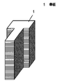
また、金属で内部が詰まった金属製部材の内、金属板から打抜いた金属単板を積層、接合するトランスやモーター等に使用される積層鉄芯の場合は、断面形状を部分によって変える必要がない単純立体形状であるため、図5の積層鉄芯の斜視図に示すように、例えば、形状が全て一定のT字状に打抜いた単板1を必要枚数積層し接着することにより積層鉄芯を得ていた。
【0004】
【発明が解決しようとする課題】
しかしながら、上記従来の方法により断面形状が部分によって異なる金属製立体形状物を製造するには、鋳物工程や切削工程を要するため、製作に時間がかかるという問題があったり、また、積層鉄芯の場合、断面形状が任意の位置にて異なる複雑な金属製立体形状物である必要性がなく、従って、形状が同一な金属単板を積層しており、そのような積層鉄芯から、断面形状が部分によって異なる金属製立体形状物を得ることを想定することはできなかった。
【0005】
本発明は上記の課題を解決するもので、断面形状が任意の位置にて異なる複雑な金属製立体形状物とその製造方法を提供することを目的とするものである。
【0006】
【課題を解決するための手段】
上記の課題を解決するために、本発明は、形状の異なる金属単板を積層、接着した断面形状が部分によって異なる金属製立体形状物とする。よって鋳物工程や切削工程を要することなく、断面形状が任意の位置にて異なる複雑な金属製立体形状物が得られるものである。
【0007】
【発明の実施の形態】
本発明の請求項1に記載の発明は、形状の異なる金属単板を積層、接着した断面形状が部分によって異なる金属製立体形状物であり、形状の異なる金属単板を積層することにより、任意の位置の断面形状が異なる複雑な金属製立体形状物が得られるという作用を有する。
【0008】
本発明の請求項2に記載の発明は、プレス金型で金属板から単板を打抜く工程に間欠的に形状の異なる単板を打抜く工程を入れ、打抜いた単板を同一プレス金型内において順次積層、接着することにより断面形状が部分によって異なる金属製立体形状物を得る金属製立体形状物の製造方法であり、間欠的に形状の異なる単板を打抜く工程を入れることにより、プレス金型内に積層される打抜いた単板の積層体は任意の位置の断面形状が異なる複雑な金属製立体形状物になるという作用を有する。
【0009】
以下、本発明の実施の形態について図面を参照しながら説明する。
【0010】
(実施の形態1)
図1(a)は本発明の実施の形態1における金属製立体形状物の斜視図、図1(b)、(c)、(d)は図1(a)に示す金属製立体形状物を構成する金属単板の斜視図、図2は図1(b)、(c)、(d)に示す金属単板の製造工程図であり、図1(a)に示す金属製立体形状物は上部から順に図1(b)に示すT字状の単板2を所定枚数、図1(c)に示すT字状の横部分先端一部3が削除された単板4を所定枚数、図1(b)に示すT字状の単板2を所定枚数、図1(d)に示すT字状の縦部分先端5が削除された単板6を所定枚数、図1(b)に示すT字状の単板2を所定枚数、図1(c)に示すT字状の横部分先端一部3が削除された単板4を所定枚数、図1(b)に示すT字状の単板2を所定枚数を積層し、接着して構成されており、両側面7には図1(c)に示すT字状の横部分先端一部3が削除された単板4を積層したことによる四角穴8が形成され、前面9には図1(d)に示すT字状の縦部分先端5が削除された単板6を積層したことによる切欠部10が形成されることになる。
【0011】
上記単板2、4、6を得るには、図2の製造工程図に示すように、順送金型により、帯状鉄板11から最終的に打抜く予定のT字状の単板2のT字状の横部分先端一部3を間欠的に打抜く第1工程と、最終的に打抜く予定のT字状の単板2のT字状の縦部分先端5を間欠的に打抜く第2工程と、最終的にT字状の単板2を打抜く第3工程とから得られる。
【0012】
例えば、図1(a)に示すような断面形状が部分によって異なる金属製立体形状物は、第1工程および第2工程において、T字状の横部分先端一部3およびT字状の縦部分先端5を打抜かないで第3工程において打抜いて得られたT字状の単板2を所定枚数最上部に積層し、その下に第1工程においてT字状の横部分先端一部3を打抜き、第2工程においてT字状の縦部分先端5を打抜かないで、第3工程において打抜いて得られたT字状の単板4を所定枚数積層するという具合に、T字状の横部分先端一部3およびT字状の縦部分先端5の打抜きを間欠的に行う第1工程および第2工程と最終的にT字状の単板を打抜く第3工程とを、金属製立体形状物に応じて、適宜、組合わせ、得られた単板2、4、6を積層、接着することにより得られる。
【0013】
なお、上記実施の形態1における金属単板の製造工程図では、T字状の横部分先端一部3およびT字状の縦部分先端5の打抜きを間欠的に行う第1工程および第2工程を最終的にT字状の単板2を打抜く第3工程の前に入れたが、第1工程および第2工程を第3工程と別の金型で行うのであれば、第3工程で最終のT字状の単板2を打抜いた後に、別の金型でT字状の横部分先端一部3およびT字状の縦部分先端5を打抜いても同様に図1(a)に示すような断面形状が部分によって異なる金属製立体形状物を得ることができる。
【0014】
(実施の形態2)
図3は本発明の実施の形態2における金属製立体形状物の斜視図、図4は図3の金属製立体形状物を構成する金属単板の製造工程図であり、図3に示す金属製立体形状物は金属で詰まった形状物12の内部に円筒空間13を形成した構成であり、形状物12を構成する金属単板は帯状鉄板14から順送金型により、間欠的に円板15を打抜き、その後で、円板15を含む四角形状単板16を打抜く。
【0015】
図3に示す金属製立体形状物は、上記のように、順送金型により得た円板15に相当する円孔のない四角形状単板16を所定枚数積層し、その下に円板15に相当する円孔のある四角形状単板16を所定枚数積層し、その下に円板15に相当する円孔のない四角形状単板16を所定枚数積層することにより、切削工程では得られない内部に円筒空間13のある形状物12を得ることができる。
【0016】
【発明の効果】
以上のように、本発明の金属製立体形状物とその製造方法によれば、鋳物工程や切削工程を要することなく、プレス工程により短い製作時間で断面形状が任意の位置にて異なる複雑な金属製立体形状物を得ることができるという効果がある。
【図面の簡単な説明】
【図1】(a)本発明の実施の形態1における金属製立体形状物の斜視図
(b)(a)に示す金属製立体形状物を構成する金属単板の斜視図
(c)(a)に示す金属製立体形状物を構成する金属単板の斜視図
(d)(a)に示す金属製立体形状物を構成する金属単板の斜視図
【図2】図1(b)、(c)、(d)に示す金属単板の製造工程図
【図3】本発明の実施の形態2における金属製立体形状物の斜視図
【図4】図3の金属製立体形状物を構成する金属単板の製造工程図
【図5】従来の積層鉄芯の斜視図
【符号の説明】
1,2,4,6 単板
3 T字状の横部分先端一部
5 T字状の縦部分先端
7 両側面
8 四角穴
9 前面
10 切欠部
11,14 帯状鉄板
12 形状物
13 円筒空間
15 円板
16 四角形状単板[0001]
TECHNICAL FIELD OF THE INVENTION
The present invention relates to a three-dimensional metal object whose cross-sectional shape is different depending on a portion, such as a metal member or a metal object whose inside is clogged with metal, and a method of manufacturing the same.
[0002]
[Prior art]
2. Description of the Related Art Conventionally, a metal member or a metal object whose inside is clogged with metal is formed by a casting process of pouring a metal material into a mold, or a final process is performed by a cutting process of a metal block using a milling machine or the like.
[0003]
In the case of laminated iron cores used for transformers, motors, etc., which are used for transformers, motors, etc., for laminating and joining single metal plates punched from a metal plate, the cross-sectional shape must be changed depending on the part As shown in the perspective view of the laminated iron core in FIG. 5, for example, the required number of
[0004]
[Problems to be solved by the invention]
However, in order to produce a three-dimensional metal product having a different cross-sectional shape depending on a portion by the above-described conventional method, a casting process or a cutting process is required. In this case, there is no need for a complicated three-dimensional metal object having a different cross-sectional shape at an arbitrary position, and thus, a single metal plate having the same shape is laminated. Could not expect to obtain three-dimensional metal objects different from part to part.
[0005]
An object of the present invention is to solve the above-mentioned problems, and an object of the present invention is to provide a complicated three-dimensional metal product having a different cross-sectional shape at an arbitrary position and a method of manufacturing the same.
[0006]
[Means for Solving the Problems]
In order to solve the above-mentioned problems, the present invention provides a three-dimensional metal product in which cross-sectional shapes obtained by laminating and bonding metal single plates having different shapes are different depending on portions. Therefore, it is possible to obtain a complicated three-dimensional metal product having a different cross-sectional shape at an arbitrary position without requiring a casting process or a cutting process.
[0007]
BEST MODE FOR CARRYING OUT THE INVENTION
The invention according to
[0008]
The invention according to
[0009]
Hereinafter, embodiments of the present invention will be described with reference to the drawings.
[0010]
(Embodiment 1)
FIG. 1A is a perspective view of a metal three-dimensional object according to the first embodiment of the present invention, and FIGS. 1B, 1C, and 1D show the metal three-dimensional object shown in FIG. FIG. 2 is a perspective view of the metal veneer to be constituted, FIG. 2 is a manufacturing process diagram of the metal veneer shown in FIGS. 1 (b), (c), and (d), and the three-dimensional metal product shown in FIG. A predetermined number of T-
[0011]
In order to obtain the
[0012]
For example, as shown in FIG. 1 (a), a three-dimensional metal product having a different cross-sectional shape depending on a portion has a T-shaped horizontal
[0013]
In the manufacturing process diagram of the metal veneer according to the first embodiment, the first step and the second step of intermittently punching the T-shaped
[0014]
(Embodiment 2)
FIG. 3 is a perspective view of a metal three-dimensional object according to
[0015]
As described above, the metal three-dimensional object shown in FIG. 3 is formed by laminating a predetermined number of square
[0016]
【The invention's effect】
As described above, according to the three-dimensional metal product of the present invention and the method of manufacturing the same, a complicated metal having a different cross-sectional shape at an arbitrary position in a short manufacturing time by a pressing process without a casting process or a cutting process. There is an effect that it is possible to obtain a three-dimensional product made of a material.
[Brief description of the drawings]
FIG. 1 (a) is a perspective view of a metal three-dimensional object according to
1, 2, 4, 6 Veneer 3 T-shaped horizontal portion tip part 5 T-shaped
Claims (2)
Priority Applications (1)
| Application Number | Priority Date | Filing Date | Title |
|---|---|---|---|
| JP2002169692A JP2004015973A (en) | 2002-06-11 | 2002-06-11 | Metal three-dimensionally formed object and its producing method |
Applications Claiming Priority (1)
| Application Number | Priority Date | Filing Date | Title |
|---|---|---|---|
| JP2002169692A JP2004015973A (en) | 2002-06-11 | 2002-06-11 | Metal three-dimensionally formed object and its producing method |
Publications (1)
| Publication Number | Publication Date |
|---|---|
| JP2004015973A true JP2004015973A (en) | 2004-01-15 |
Family
ID=30436174
Family Applications (1)
| Application Number | Title | Priority Date | Filing Date |
|---|---|---|---|
| JP2002169692A Withdrawn JP2004015973A (en) | 2002-06-11 | 2002-06-11 | Metal three-dimensionally formed object and its producing method |
Country Status (1)
| Country | Link |
|---|---|
| JP (1) | JP2004015973A (en) |
Cited By (1)
| Publication number | Priority date | Publication date | Assignee | Title |
|---|---|---|---|---|
| CN113275459A (en) * | 2021-07-22 | 2021-08-20 | 宁波震裕科技股份有限公司 | Manufacturing process of step type iron core |
-
2002
- 2002-06-11 JP JP2002169692A patent/JP2004015973A/en not_active Withdrawn
Cited By (2)
| Publication number | Priority date | Publication date | Assignee | Title |
|---|---|---|---|---|
| CN113275459A (en) * | 2021-07-22 | 2021-08-20 | 宁波震裕科技股份有限公司 | Manufacturing process of step type iron core |
| CN113275459B (en) * | 2021-07-22 | 2021-09-14 | 宁波震裕科技股份有限公司 | Manufacturing process of step type iron core |
Similar Documents
| Publication | Publication Date | Title |
|---|---|---|
| JPH0521050B2 (en) | ||
| JP2004015973A (en) | Metal three-dimensionally formed object and its producing method | |
| KR101990696B1 (en) | Apparatus for Manufacturing Laminated Core by Adhesion with Easy Separation of Cores | |
| JP2572669B2 (en) | Press die manufacturing method | |
| JP3776052B2 (en) | Laminated iron core | |
| JP3565692B2 (en) | Manufacturing method of perforated floor panel | |
| JP3004417U (en) | Bobbin shaped core | |
| JPS5925563Y2 (en) | Iron core forming equipment | |
| JP2579430B2 (en) | Die for forming object | |
| JP2001277058A (en) | Compound plate working method including laser beam machining and pressing | |
| JP2009136621A (en) | Jigsaw puzzle and its manufacturing method | |
| JPS6041712Y2 (en) | Iron core forming equipment | |
| JPH05138442A (en) | Method for forming laminated body of sendust alloy thin plate and parts thereof | |
| JPH04306374A (en) | Key with inside keyway and manufacture thereof | |
| JPS5968812A (en) | Manufacture of magnetic head core | |
| JPH09136121A (en) | Bend machining die structure body | |
| JPS6235802A (en) | Cold hydrostatic pressing molding method | |
| JPH01309751A (en) | Manufacture of metallic mold | |
| JPH0711931Y2 (en) | Formwork for flat plate block with pattern | |
| JPH0553735U (en) | Die for press working | |
| JPS60137528A (en) | Minute joining system of pressed product | |
| JPS63114203A (en) | Manufacture of laminated magnetic core | |
| JPH0628242Y2 (en) | Demon tile molding equipment | |
| JPH04319034A (en) | Manufacture of inner groove key | |
| JPH09141364A (en) | Production of thin-walled seamless ring and thin-walled seamless ring |
Legal Events
| Date | Code | Title | Description |
|---|---|---|---|
| RD03 | Notification of appointment of power of attorney |
Effective date: 20041119 Free format text: JAPANESE INTERMEDIATE CODE: A7423 |
|
| RD04 | Notification of resignation of power of attorney |
Free format text: JAPANESE INTERMEDIATE CODE: A7424 Effective date: 20050221 |
|
| A621 | Written request for application examination |
Effective date: 20050317 Free format text: JAPANESE INTERMEDIATE CODE: A621 |
|
| RD01 | Notification of change of attorney |
Effective date: 20050707 Free format text: JAPANESE INTERMEDIATE CODE: A7421 |
|
| A977 | Report on retrieval |
Effective date: 20060719 Free format text: JAPANESE INTERMEDIATE CODE: A971007 |
|
| A761 | Written withdrawal of application |
Free format text: JAPANESE INTERMEDIATE CODE: A761 Effective date: 20061101 |