JP2004015831A - Remote controller control system for devices connected to bus and program storage medium - Google Patents
Remote controller control system for devices connected to bus and program storage medium Download PDFInfo
- Publication number
- JP2004015831A JP2004015831A JP2003325037A JP2003325037A JP2004015831A JP 2004015831 A JP2004015831 A JP 2004015831A JP 2003325037 A JP2003325037 A JP 2003325037A JP 2003325037 A JP2003325037 A JP 2003325037A JP 2004015831 A JP2004015831 A JP 2004015831A
- Authority
- JP
- Japan
- Prior art keywords
- key code
- remote controller
- controller
- bus
- key
- Prior art date
- Legal status (The legal status is an assumption and is not a legal conclusion. Google has not performed a legal analysis and makes no representation as to the accuracy of the status listed.)
- Pending
Links
Images


Abstract
Description
本発明は、バスに接続された機器をリモートコントローラによって制御するバス接続機器のリモコン制御システム及びプログラム記録媒体に関するものである。 The present invention relates to a remote control system for a bus-connected device that controls a device connected to a bus by a remote controller, and a program recording medium.
バスに接続された複数の機器をリモートコントローラを用いて制御するバス接続機器のリモコン制御システムがある。 リ モ コ ン There is a remote control system for bus-connected devices that controls a plurality of devices connected to the bus using a remote controller.
以下、このリモコン制御システムについて、図15を参照して説明する。 Hereinafter, this remote control system will be described with reference to FIG.
図15は、このバス接続機器のリモコン制御システムのコントローラ50とターゲット22の構成を示したものである。
FIG. 15 shows a configuration of the
バス1には、STB(セットトップボックス:衛星放送受信器)、VTR、TVなど複数台の機器が接続されている。このうち1台がコントローラ50の機能を兼ねている。また、バス1に接続されている複数台のうちいずれか一つの機器がコントローラ50によって制御されるターゲット22である。
A plurality of devices such as an STB (set top box: satellite receiver), VTR, and TV are connected to the bus 1. One of them also functions as the
例えば、STBがコントローラ50の機能を兼ねており、ターゲット22がVTRであるとする。
{For example, it is assumed that the STB also functions as the
コントローラ50は、リモートコントローラ(図示せず)から送られてくる指示を表すキーコードを受信し、この指示に基づいてターゲット22を制御する機器である。
The
ターゲット22は、コントローラ50から送られてくる指示を実行する機器である。
The
コントローラ50は、リモコン受信部16、コード選択部15、命令実行部17、デジタルI/F51、GUI情報取得部13、表示部14から構成される。
The
また、ターゲット22は、デジタルI/F23、キーコード検出部24、命令実行部25、GUI情報出力部26から構成される。
The
コントローラ50を構成するリモコン受信部16は、リモートコントローラから送られてくるキーコードを受信する手段である。
The remote
コード選択部15は、リモートコントローラから送られてくるキーコードの内容によって、そのキーコードを命令実行部17に送るかそれともデジタルI/F51に送るかを決定する手段である。
The
命令実行部17は、リモートコントローラで指示された命令を実行する手段である。コントローラ50は、STBの機能を兼ねているので、命令実行部17で実行される命令は、受信するチャンネルの切り替え、STBの主電源のオンオフ、音量の調節などSTBを制御する命令である。
The
デジタルI/F51は、AVデータを他の機器とやりとりすることに加えて、ターゲット22を制御するキーコードをターゲット22に送り、また、ターゲット22からGUI情報を受け取る手段である。
The digital I /
GUI情報取得部13は、デジタルI/F51から、ターゲット22の機能を制御するためのGUI情報を取得する手段である。
The 情報 GUI
表示部14は、GUI情報をSTBに接続されているモニタにOSD(On Screen Display)出力する手段である。
The
また、ターゲット22を構成するデジタルI/F23は、AVデータを他の機器とやりとりすることに加えて、コントローラ50にGUI情報を送り、コントローラ50からの指示を表すキーコードを受け取る手段である。
The digital I /
キーコード検出部24は、デジタルI/F23から送られてくるキーコードを検出し、動作命令を表すキーコードであれば命令実行部25に送り、GUI更新命令であればGUI情報出力部26に送る手段である。
The key
命令実行部25は、キーコードで表される命令を実行する手段である。ターゲット22は、VTRであるので、命令実行部25が実行する命令は、再生開始、再生終了、録画開始、録画終了などの命令のようにVTRを制御する命令である。
The
GUI情報出力部26は、GUI更新命令に従ってGUI情報をデジタルI/F23に出力する手段である。
The GUI
次に、このようなバス接続機器のリモコン制御システムの動作について説明する。 Next, the operation of the remote control system for such a bus-connected device will be described.
ターゲット22のGUI情報出力部26は、自らを制御するのに必要なGUI情報をデジタルI/F23に出力する。
The GUI
デジタルI/F23は、このGUI情報をバス1を介して、コントローラ50のデジタルI/F51に送る。
The digital I /
デジタルI/F51は、受信したGUI情報をGUI情報取得部13に送る。
The digital I /
GUI情報取得部13は、GUI情報を表示部14に送り、表示部14はGUI情報をOSD出力する。
The GUI
このようにして、ターゲット22を制御するためのGUIがコントローラ50を兼ねるSTBのモニタに表示される。
に し て In this way, the GUI for controlling the
ユーザは、このモニタのGUI画面を見ながら、リモートコントローラを操作する。 The user operates the remote controller while viewing the GUI screen of this monitor.
ユーザがリモートコントローラの操作キーを操作したとする。そうすると、リモートコントローラは、対応するキーコードをリモコン受信部16に送出する。
と す る It is assumed that the user operates the operation keys of the remote controller. Then, the remote controller sends the corresponding key code to
リモコン受信部16は、リモートコントローラから送られてきたキーコードを受信する。
(4) The
コード選択部15は、キーコードが自機器あてのキーコードである場合、命令実行部17にそのキーコードを送り、他機器を制御するキーコードである場合、デジタルI/F51にそのキーコードを送る。
If the key code is a key code addressed to the own device, the
例えば、受信チャンネルを変更するキーコードは自機器あてのキーコードであり、再生を開始するキーコードは他機器を制御するキーコードである。 For example, the key code for changing the receiving channel is a key code for the own device, and the key code for starting reproduction is a key code for controlling another device.
リモートコントローラから受信チャンネルを変更するキーコードが送られてきたとする。 と す る It is assumed that a key code for changing the reception channel has been sent from the remote controller.
この場合、コード選択部15は、受信チャンネルを変更するキーコードを命令実行部17に送り、命令実行部17は、コントローラ50の機能を兼ねているSTBの受信チャンネルを変更する。
In this case, the
また、リモートコントローラから再生を開始するキーコードが送られてきたとする。 と す る Also, assume that a key code for starting playback is sent from the remote controller.
この場合、コード選択部15は、再生を開始するキーコードをデジタルI/F51に送り、デジタルI/F51は、このキーコードをバス1を介してターゲット22に送る。
In this case, the
ターゲット22のデジタルI/F23は、このキーコードを受け取り、キーコード検出部24に渡す。
The digital I /
キーコード検出部24は、キーコードを検出し、このキーコードがVTRを制御するキーコードであるので、命令実行部25に送る。
(4) The key
命令実行部25は、VTRの再生を開始する。
(4) The
コントローラ50は、このようにターゲット22を制御する際、リモートコントローラのキーコードの内容を理解する必要がなくターゲット22へキーコードの転送を行うだけでよい。
When controlling the
また、ユーザがSTBのモニタに表示されているGUI画面を見ながら、サブメニューを表示するようリモートコントローラを操作したとする。 と す る Further, it is assumed that the user operates the remote controller to display a submenu while looking at the GUI screen displayed on the monitor of the STB.
そうすると、リモートコントローラはそのキーコードを送出する。 Then, the remote controller sends out the key code.
リモコン受信部16は、リモートコントローラから送られてくるキーコードを受信する。
(4) The
コード選択部15は、キーコードが他機器を制御するキーコードであることを判別し、キーコードをデジタルI/F51に送る。
The
デジタルI/F51は、バス1を介して、キーコードをターゲット22に送る。
The digital I /
デジタルI/F23は、キーコードを受信し、キーコード検出部24に送る。
The digital I /
キーコード検出部24は、キーコードを検出し、このキーコードがGUIを更新する命令であるので、GUI情報出力部26に送る。
The key
GUI情報出力部26は、対応するGUI情報をデジタルI/F23に出力する。
The GUI
デジタルI/F23は、GUI情報をバス1を介してコントローラ50に送る。
The digital I /
デジタルI/F51は、GUI情報を受信し、GUI情報取得部13に送る。
The digital I /
GUI情報取得部13は、GUI情報を表示部13に出力し、表示部14は、GUI情報をSTBに接続されているモニタにOSD出力する。
(4) The GUI
このようにしてGUI画面が更新される。ユーザは、更新されたGUI画面を見ながら、リモートコントローラで操作を継続して行う。 よ う The GUI screen is updated in this way. The user continues to operate the remote controller while viewing the updated GUI screen.
このようなバス接続機器のリモコン制御システムでは、一つのリモートコントローラによって、バスに接続されているターゲットやコントローラを兼ねる機器を制御することが出来る。 In such a remote control system for a bus-connected device, a single remote controller can control a target connected to the bus and a device also serving as a controller.
しかしながら、バス上にいろいろな機器がつながれると、上記バス接続機器のリモコン制御システムでは、どの機器にキーコードを送るかを決める手法がない。すなわち、被制御機器を切り替える手法がないという課題がある。 However, when various devices are connected to the bus, the remote control system for the bus-connected devices does not have a method of determining which device sends the key code. That is, there is a problem that there is no method for switching the controlled device.
また、リモートコントローラにはキーがあるが、いろいろな機器を操作するためにはキーの数が限られている。すなわち、リモートコントローラにキーの数が限られており、リモートコントローラで操作出来る機能が限られてしまうという課題がある。 Although remote controllers have keys, the number of keys is limited to operate various devices. That is, there is a problem that the number of keys is limited in the remote controller, and the functions that can be operated by the remote controller are limited.
また、バス上にいろいろな機器がつながれると、リモートコントローラでどの機器を操作しているのかを常に意識しておく必要がある。そうでないと、例えば、アンプから音が出ているのに、テレビの音を調節してしまったりする場合が起こりうる。すなわち、被制御機器をユーザに意識させることなく、制御できないという課題がある。 と Also, when various devices are connected on the bus, it is necessary to always be aware of which device is being operated by the remote controller. Otherwise, for example, the sound of the television may be adjusted while the sound is being output from the amplifier. That is, there is a problem that the controlled device cannot be controlled without making the user aware of the device.
本発明は、バス上にいろいろな機器がつながれると、どの機器を被制御機器にするかを切り替える手法がないという課題を考慮し、バス上にいろいろな機器がつながれている場合、どの機器を被制御機器にするかを切り替える手法を持つバス接続機器のリモコン制御システム及びプログラム記録媒体を提供することを目的とする。 The present invention takes into consideration the problem that when various devices are connected on the bus, there is no method of switching which device is to be the controlled device, and when various devices are connected on the bus, An object of the present invention is to provide a remote control system and a program recording medium for a bus-connected device having a method of switching whether to be a controlled device.
また、本発明は、バス上にいろいろな機器がつながれると、リモートコントローラのキーの数が限られており、リモートコントローラで操作出来る機能が限られてしまうという課題を考慮し、バス上にいろいろな機器がつながれると、リモートコントローラのキーの数が限られていても、リモートコントローラで操作出来る機能が限られないバス接続機器のリモコン制御システム及びプログラム記録媒体を提供することを目的とする。 In addition, the present invention takes into account the problem that when various devices are connected on the bus, the number of keys on the remote controller is limited, and the functions that can be operated by the remote controller are limited. It is an object of the present invention to provide a remote control system and a program recording medium for a bus-connected device in which functions that can be operated by the remote controller are not limited even when the number of keys of the remote controller is limited when the various devices are connected.
また、本発明は被制御機器をユーザに意識させることなく、制御できないという課題を考慮し、被制御機器をユーザに意識させることなく、制御することが出来るバス接続機器のリモコン制御システム及びプログラム記録媒体を提供することを目的とする。 In addition, the present invention considers the problem that a controlled device cannot be controlled without being conscious of the user, and a remote control system and a program recording device for a bus-connected device that can control the controlled device without being conscious of the user. The purpose is to provide a medium.
上述した課題を解決するために、第1の本発明は、バスと、
前記バスに接続された複数個の機器と、
前記複数個の機器のうちいずれか一つの機器を制御するリモートコントローラとを備え、
前記複数個の機器のうちいずれか一つの機器が、前記リモートコントローラによって制御されるコントローラとしての機能を有し、
前記複数個の機器のうち、全部または二つ以上の機器が前記リモートコントローラによって制御される被制御機器であり、
前記コントローラを兼ねる機器は、前記リモートコントローラからの指示を前記被制御機器に伝えるものであり、
前記コントローラは、前記リモートコントローラから送られてくる指示を表すキーコードを前記被制御機器に送ることを特徴とするバス接続機器のリモコン制御システムである。
In order to solve the above-described problem, a first present invention provides a bus,
A plurality of devices connected to the bus,
A remote controller for controlling any one of the plurality of devices,
Any one of the plurality of devices has a function as a controller controlled by the remote controller,
Among the plurality of devices, all or two or more devices are controlled devices controlled by the remote controller,
The device also serving as the controller is for transmitting an instruction from the remote controller to the controlled device,
The controller is a remote control system for a bus-connected device, wherein the controller sends a key code indicating an instruction sent from the remote controller to the controlled device.
また、第2の本発明は、前記コントローラは、前記キーコードを前記被制御機器に送る前に、各機器を調べておいて、前記キーコードを処理する機能を持つ機器のみに前記被制御機器として前記キーコードを送ることを特徴とする第1の本発明のバス接続機器のリモコン制御システムである。 Further, in the second invention, the controller checks each device before sending the key code to the controlled device, and checks the controlled device only for a device having a function of processing the key code. The first aspect of the present invention is a remote control system for a bus-connected device according to the present invention, wherein the key code is transmitted.
また、第3の本発明は、前記キーコードは、電源を入れる及び切ることであり、
前記コントローラが電源を切るキーコードを送る前に、前記コントローラは、各機器が電源が入っているか切れているかを調べておいて、前記電源を切るキーコードを電源が入っている前記機器に送って電源を切り、
その後、電源を入れる際に、前記調べておいた電源が入っていた機器のみ電源を入れるキーコードを送ることを特徴とする第2の本発明のバス接続機器のリモコン制御システムである。
In a third aspect of the present invention, the key code is to turn on and off power.
Before the controller sends a key code to turn off the power, the controller checks whether each device is turned on or off, and sends the key code to turn off the power to the device that is turned on. Power off,
After that, when the power is turned on, a key code for turning on the power is sent only to the device that has been turned on, and the remote control control system for a bus-connected device according to the second aspect of the present invention is provided.
また、第4の本発明は、前記バスは、IEEE1394バスであることを特徴とする第1〜3の本発明のいずれかのバス接続機器のリモコン制御システムである。 A fourth invention is the remote control system for a bus-connected device according to any one of the first to third inventions, wherein the bus is an IEEE 1394 bus.
また、第5の本発明は、第1〜4の本発明のいずれかのバス接続機器のリモコン制御システムのリモートコントローラ、コントローラ、被制御機器、バスに接続されている複数の機器の機能をコンピュータにより実行させるためのプログラムを記録した、コンピュータにより読み取り可能なことを特徴とするプログラム記録媒体である。 According to a fifth aspect of the present invention, there is provided a remote controller for a remote control system for a bus-connected device according to any one of the first to fourth aspects of the present invention. A program recording medium which records a program to be executed by a computer and is readable by a computer.
本発明は、バス上にいろいろな機器がつながれている場合、どの機器を被制御機器にするかを切り替える手法を持つバス接続機器のリモコン制御システム及びプログラム記録媒体を提供することが出来る。 According to the present invention, it is possible to provide a remote control system for a bus-connected device and a program recording medium having a method of switching which device is a controlled device when various devices are connected to a bus.
また、本発明は、バス上にいろいろな機器がつながれると、リモートコントローラのキーの数が限られていても、リモートコントローラで操作出来る機能が限られないバス接続機器のリモコン制御システム及びプログラム記録媒体を提供することが出来る。 Further, the present invention provides a remote control system and a program recording system for a bus-connected device in which, when various devices are connected to a bus, even if the number of keys on the remote controller is limited, the functions that can be operated by the remote controller are not limited. A medium can be provided.
また、本発明は、被制御機器をユーザに意識させることなく、制御することが出来るバス接続機器のリモコン制御システム及びプログラム記録媒体を提供することが出来る。 The present invention can also provide a remote control system for a bus-connected device and a program recording medium that can control a controlled device without making the user conscious of the device.
以下に、本発明の実施の形態について図面を参照して説明する。 Hereinafter, embodiments of the present invention will be described with reference to the drawings.
(第1の実施の形態)
まず、第1の実施の形態について説明する。
(First Embodiment)
First, a first embodiment will be described.
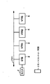
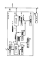
図1に、本実施の形態のバス接続機器のリモコン制御システムの構成を示す。 FIG. 1 shows a configuration of a remote control system for a bus-connected device according to the present embodiment.
バス1にSTB2、VTR1(3)、VTR2(4)、VTR3(5)が接続されている。また、これらのバス1に接続された機器を制御するリモートコントローラ30がある。 STSTB2, VTR1 (3), VTR2 (4), VTR3 (5) are connected to the bus 1. Further, there is a remote controller 30 for controlling devices connected to the bus 1.
バス1は、IEEE1394−1995に記述されているIEEE standard for High performance Serial Busであり、機器間でAVデータやコマンドをやりとりするものである。 The bus 1 is an IEEE standard for High High performance Serial Bus described in IEEE 1394-1995, and is used for exchanging AV data and commands between devices.
STB2は、セットトップボックス(衛星放送受信器)であり、衛星放送を受信して、モニタに表示したり、受信したAVデータをバス1を介して、他の機器へ転送したり、また、他の機器から送られてきたAVデータをモニタに表示したりする機器である。
VTR1(3)、VTR2(4)、VTR3(5)は、AVデータを記録再生するビデオテープレコーダである。 VTR1 (3), VTR2 (4), VTR3 (5) are video tape recorders for recording and reproducing AV data.
STB2、VTR1(3)、VTR2(4)、VTR3(5)は、IEEE1394においてAV信号を伝送するためのSpecifications of Digital Interface for consumer Electronic Equipment(通称AVプロトコル)と、機器の制御コマンドを送るためのAV/C command transaction setに基づいて、バス1を介して、AVデータやコマンドのやりとりを行う。 The STB2, VTR1 (3), VTR2 (4), and VTR3 (5) transmit Specifications of Digital Digital Interface for Consumer Electronic Equipment and a device control command for transmitting AV signals in IEEE1394. AV data and commands are exchanged via the bus 1 based on AV / C \ command \ transaction \ set.
リモートコントローラ30は、バス1に接続されている機器であるSTB2、VTR1(3)、VTR2(4)、VTR3(5)を操作する手段である。 (4) The remote controller 30 is means for operating the devices connected to the bus 1 such as STB2, VTR1 (3), VTR2 (4), and VTR3 (5).
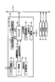
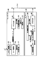
図2に各機器の構成のうち、コントローラ6の構成を示す。コントローラ6は、リモートコントローラ30からの指示に基づいて、バス1に接続されている機器を制御する機器である。本実施の形態ではSTB2がコントローラ6の機能を兼ねている。
FIG. 2 shows the configuration of the
コントローラ6は、デジタルI/F10、転送先記憶手段11、バス構成記憶手段12、GUI情報取得部13、表示部14、コード選択部15、リモコン受信部16、命令実行部17から構成される。
The
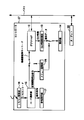
また、図3にSTB2の構成のうち、コントローラ6以外の部分を示す。STB2は、デジタルI/F10、チューナ18、デスクランブラ19、トランスポートデコーダ20、AVデコーダ21から構成される。また、STB2には、アンテナ3、モニタ7が接続されている。
FIG. 3 shows a portion of the configuration of the
図4にターゲット22の構成を示す。ターゲット22は、VTR1(3)、VTR2(4)、VTR3(5)のうち、リモートコントローラ30から送られてくるキーコードを処理する部分であり、そのうちいずれか一つがコントローラ6によって制御される被制御機器である。
FIG. 4 shows the configuration of the
ターゲット22は、デジタルI/F23、キーコード検出部24、命令実行部25、GUI情報出力部26から構成される。
The
コントローラ6を構成するデジタルI/F10は、AVデータを他の機器とやりとりすることに加えて、ターゲット22を制御するキーコードをターゲット22に送り、また、ターゲット22からGUI情報を受け取り、バスリセット検出時に機器構成をバス構成記憶手段12に記憶させ、キーコードを転送する転送先を転送先記憶手段11に記憶させる手段である。
The digital I /
転送先記憶手段11は、リモートコントローラ30から送られてきたキーコードのうち他機器を制御するキーコードの転送先を記憶する手段である。他機器制御コードは、転送先記憶手段11に記憶されている転送先に転送される。
The transfer
バス構成記憶手段12は、機器構成を記憶する手段である。
The bus
GUI情報取得部13は、デジタルI/F10から、ターゲット22の機能を制御するためのGUI情報を取得する手段である。
The 情報 GUI
表示部14は、GUI情報をSTB2に接続されているモニタ7にOSD(On Screen Display)出力する手段である。
The
コード選択部15は、リモートコントローラ30から送られてくるキーコードの内容によって、そのキーコードを命令実行部17に送るかそれともデジタルI/F10に送るかを決定する手段である。
The
リモコン受信部16は、リモートコントローラ30から送られてくるキーコードを受信する手段である。
The
命令実行部17は、リモートコントローラ30で指示された命令を実行する手段である。STB2はコントローラ6の機能を兼ねているので、命令実行部17で実行される命令は、受信するチャンネルの切り替え、STB2の主電源のオンオフ、音量の調節などSTB2を制御する命令である。
The
また、STB2を構成するデジタルI/F10は、コントローラ6のインターフェースの機能を兼ねており、AVデータをやり取りする手段である。
The digital I /
チューナ18は、放送局から送られてくる放送波を受信し、復調する手段である。
The
デスクランブラ19は、復調されたAVデータが放送用に暗号化されている場合は、暗号を解読する手段である。
The
なお、AVデータはMPEG2トランスポートストリームとして送られてくるものとする。ここで、MPEGとはMotion Picture Expert Groupの略であり、MPEG2は、ISO/IECにおける規格番号13818の規格である。 Note that the AV data is sent as an MPEG2 transport stream. Here, MPEG is an abbreviation of Motion Picture Expert Group, and MPEG2 is a standard of standard number 13818 in ISO / IEC.
トランスポートデコーダ20は、MPEG2トランスポートストリームを分離する手段である。
The
AVデコーダ21は、分離された圧縮されているAVデータを伸長し、アナログ信号に変換する手段である。
The
アンテナ3は、放送波を電気信号に変換する手段である。またモニタ7は、AVデータを表示し、また被制御機器から送られてくるGUI情報を表示する手段である。
The
また、ターゲット22を構成するデジタルI/F23は、AVデータを他の機器とやりとりすることに加えて、コントローラ50にGUI情報を送り、コントローラ50からの指示を表すキーコードを受け取る手段である。
The digital I /
キーコード検出部24は、デジタルI/F23から送られてくるキーコードを検出し、動作命令を表すキーコードであれば命令実行部25に送り、GUI更新命令であればGUI情報出力部26に送る手段である。
The key
命令実行部25は、キーコードで表される命令を実行する手段である。ターゲット22は、VTRであるので、命令実行部25が実行する命令は、再生開始、再生終了、録画開始、録画終了などの命令のようにVTRを制御する命令である。
The
GUI情報出力部26は、GUI更新命令に従ってGUI情報をデジタルI/F23に出力する手段である。
The GUI
次に、このような本実施の形態の動作を説明する。 Next, the operation of the present embodiment will be described.
デジタルI/F10は、バスリセット検出時にバス1に接続している機器の構成を調べ、各機器の名称とノード番号をバス構成記憶手段12に記憶させる。
The digital I /
今、STB2が63チャンネルとBroadcast in connectionを張っているとする。そして、VTR1(3)が、63チャンネルとBroadcast out connectionを張っているとする。すなわち、VTR1(3)が再生したAVデータは、STB2に入力され、STB2のモニタ7に出力されているとする。
と す る Now, suppose that STB2 has Broadcast in connection with 63 channels. Then, it is assumed that the VTR 1 (3) has Broadcast \ out \ connection with 63 channels. That is, it is assumed that the AV data reproduced by the VTR 1 (3) is input to the
デジタルI/F10は、一定の時間毎例えば1分間に一回毎に63チャンネルにBroadcast out connectionを張っている機器を調べ、その機器の名称とノード番号を転送先記憶手段11に記憶させる。現在、VTR1(3)が63チャンネルとBroadcast out connectionを張っているので、VTR1(3)の名称とノード番号が転送先記憶手段11に記憶されている。
The digital I /
ただし、リモートコントローラ30による被制御機器の切り替えが行われた時は、63チャンネルとBroadcast out connectionを張っている機器が被制御機器以外の機器に変更されても、リモートコントローラ30による被制御機器の切り替えが行われてから3分間の間、デジタルI/F10は、被制御機器のノード番号と機器の名称を転送先記憶手段11に記憶したままにする。この点については後述する。
However, when switching of the controlled device by the remote controller 30 is performed, even if the device having Broadcast {out} connection with 63 channels is changed to a device other than the controlled device, the controlled device of the controlled device by the remote controller 30 is changed. For three minutes after the switching is performed, the digital I /
Broadcast out connectionは、他の機器によって切断することが可能である。すなわち、ユーザがVTR2(4)の操作パネルにある再生キーを押した場合、VTR2(4)は、VTR1(3)が張っているBroadcast out connectionを切断し、自分自身がBroadcast out connectionを63チャンネルに張る。デジタルI/F10は、前回調べてから1分間経過したときに、63チャンネルにBroadcast out connectionを張っている機器を調べ、VTR2(4)の名称とノード番号を転送先記憶手段11に記憶させる。
\ Broadcast \ out \ connection can be disconnected by another device. That is, when the user presses the play key on the operation panel of the VTR 2 (4), the VTR 2 (4) disconnects the Broadcast \ out \ connection on the VTR 1 (3), and the Broadcast \ out \ connection changes to 63 channels. Stretch. When one minute has passed since the last check, the digital I /
63チャンネルにBroadcast out connectionを張っている機器がVTR1(3)であるとする。転送先記憶手段11に記憶されている機器の名称は、デジタルI/F10を介して、GUI取得部13に送られ、表示部14でOSD出力される。その結果、図5に示すようにモニタ7の画面の右上にVTR1(3)の名称である「VTR1」が表示される。
It is assumed that the device having Broadcast out connection on channel 63 is VTR1 (3). The device name stored in the transfer
転送先記憶手段11に記憶されている機器は、リモートコントローラ30の制御対象となる。
(4) The devices stored in the transfer
以下、リモートコントローラ30によって、転送先記憶手段11に記憶されている機器が制御される動作について説明する。
Hereinafter, an operation in which the device stored in the transfer
すなわち、VTR1(3)の名称とノード番号が、転送先記憶手段11に記憶されている場合に、ユーザがリモートコントローラ30の早送り再生キーを押すと、リモートコントローラ30は、早送り再生を指示するキーコードを送出する。
That is, when the name of the VTR 1 (3) and the node number are stored in the transfer
リモコン受信部16は、このキーコードを受信し、コード選択部15にキーコードを送る。
(4) The
コード選択部15は、自らを制御するキーコードか、他機器を制御するキーコードかを判定する。そして自らを制御するキーコードは命令実行部17に送り、他機器を制御するキーコードはデジタルI/F10に送る。ちなみに、自らを制御するキーコードが命令実行部17に送られると、命令実行部17は、このキーコードの指示内容を実行する。例えばSTB2のチューナ18の受信チャンネルを変更するなどの命令を実行する。
The
今リモートコントローラから送られてきた早送り再生を指示するキーコードは他機器を制御するキーコードであるので、コード選択部15は、このキーコードをデジタルI/F10に送る。
Since the key code for instructing fast-forward playback sent from the remote controller is a key code for controlling another device, the
デジタルI/F10は、転送先記憶手段11に記憶されている機器の名称とノード番号を参照し、コード選択部15から送られてきたキーコードを転送先記憶手段11に記憶されているノード番号の機器に転送する。すなわち、前述したように、VTR1(3)にこのキーコードが転送される。このように、コントローラ6は、リモートコントローラ30から送られてくるキーコードを被制御機器に転送する。
The digital I /
VTR1(3)は、ターゲット22としてこのキーコードを受信する。すなわち、デジタルI/F23は、このキーコードを受信し、キーコード検出部24に送る。
$ VTR1 (3) receives this key code as
キーコード検出部24がキーコードを判別する。キーコードがGUI更新命令であれば、GUI情報出力部26にキーコードを送る。キーコードが動作命令であれば、命令実行部25にキーコードを送る。今送られてきたキーコードは早送り再生を指示するキーコードであるので、キーコード検出部24は、命令実行部25にキーコードを送る。
(4) The key
命令実行部25は、早送り再生を実行する。
(4) The
このように、リモートコントローラ30によって、VTR1(3)を早送り再生するよう制御することが出来る。 As described above, the remote controller 30 can control the VTR 1 (3) to perform fast forward reproduction.
つまり、ディフォルトとして、リモートコントローラ30の被制御対象となる機器は、63チャンネルにBroadcast out connectionを張っている機器である。 In other words, as a default, the device to be controlled by the remote controller 30 is a device having Broadcast \ out \ connection on 63 channels.
また、リモートコントローラ30は、VTR1(3)がディフォルトとして被制御対象となっているので、早送り再生だけでなく、再生、スチル、巻き戻し再生、記録、記録ポーズ、停止、早送り、巻き戻しなど自由にVTR1(3)を制御することが出来る。 Further, since the VTR 1 (3) is controlled as a default, the remote controller 30 can freely perform not only fast forward playback but also playback, still, rewind playback, recording, recording pause, stop, fast forward, and rewind. VTR1 (3) can be controlled.
以上、リモートコントローラ30によって、転送先記憶手段11に記憶されている機器が制御される動作について説明した。
The operation in which the device stored in the transfer
次に、ユーザがVTR3(5)に記録されているAVデータを再生しようとしたとする。この場合、前述したように、VTR3(5)の操作パネルの再生キーを押してもVTR3(5)を再生することは可能である。ここではこれとは別の方法について説明する。 Next, suppose that the user tries to reproduce the AV data recorded on the VTR 3 (5). In this case, as described above, it is possible to reproduce the VTR 3 (5) even by pressing the reproduction key on the operation panel of the VTR 3 (5). Here, another method will be described.
すなわち、リモートコントローラ30を用いて、リモートコントローラ30の制御の対象となる機器を切り替える動作について説明する。 {That is, an operation of switching a device to be controlled by the remote controller 30 using the remote controller 30 will be described.
ユーザがVTR3(5)に記録されているAVデータを再生しようとした時点で、モニタ7の画面には、図5のように右上に「VTR1」という文字が表示されている。すなわち、VTR1(3)がリモートコントローラ30の制御の対象となっている。 (5) When the user attempts to reproduce the AV data recorded on the VTR 3 (5), the character "VTR1" is displayed on the upper right of the screen of the monitor 7 as shown in FIG. That is, the VTR 1 (3) is controlled by the remote controller 30.
そこで、ユーザは、リモートコントローラ30の機器切り替えキーを押す。 Therefore, the user presses the device switching key of the remote controller 30.
そうすると、リモートコントローラ30は、機器切り替えを指示するキーコードを送出する。 Then, the remote controller 30 sends out a key code for instructing device switching.
リモコン受信部16は、リモートコントローラ30から送られてきたキーコードを受信し、コード選択部15に送る。
The
コード選択部15は、キーコードを判別する。すなわち、送られてきたキーコードが転送先を変更するキーコードであるので、デジタルI/F10にそのキーコードを送る。
The
デジタルI/F10は、転送先記憶手段11に記憶されている機器の名称とノード番号を参照する。そして、バス構成手段12に記憶されているノード番号で、転送先記憶手段11に記憶されていたノード番号の次に番号が大きいノード番号とそのノード番号の機器の名称を転送先記憶手段11に記憶させる。転送先記憶手段11に記憶されていたノード番号より番号が大きいノード番号がない場合は、最も番号が小さいノード番号とそのノード番号の機器の名称を転送先記憶手段11に記憶させる。このようにして新たに転送先記憶手段11に記憶された機器の名称がVTR2(4)を表す「VTR2」であったとする。
The digital I /
さらに、デジタルI/F10は、新たに転送先記憶手段11に記憶された機器の名称を含むGUI情報をGUI情報取得部13に送る。
(4) Further, the digital I /
GUI情報取得部13はGUI情報を表示部14に出力する。
(4) The GUI
表示部14は、モニタ7にOSD出力する。
(4) The
その結果、図5のようにモニタ7の画面の右上に「VTR1」と表示されていたのが、切り替わり「VTR2」と表示される。このようにして、リモートコントローラ30の制御の対象となる機器を、VTR1(3)からVTR2(4)に切り替えることが出来る。 (5) As a result, what is displayed as “VTR1” at the upper right of the screen of the monitor 7 as shown in FIG. 5 is switched to “VTR2”. In this way, the device to be controlled by the remote controller 30 can be switched from the VTR 1 (3) to the VTR 2 (4).
STB2、VTR1(3)、VTR2(4)、VTR3(5)の名称がそれぞれ「STB」、「VTR1」、「VTR2」、「VTR3」であり、ノード番号がこの順に増加しているとする。 Assume that the names of STB2, VTR1 (3), VTR2 (4), and VTR3 (5) are “STB”, “VTR1”, “VTR2”, and “VTR3”, respectively, and the node numbers are increasing in this order.
そうすると、以上の説明と同様にして、さらにユーザが、リモートコントローラ30の機器切り替えキーを押すと、リモートコントローラ30の制御の対象となる機器がVTR2(4)からVTR3(5)に切り替わり、モニタ7の画面の右上には「VTR3」と表示される。 Then, similarly to the above description, when the user further presses the device switching key of the remote controller 30, the device to be controlled by the remote controller 30 is switched from the VTR 2 (4) to the VTR 3 (5), and the monitor 7 "VTR3" is displayed in the upper right corner of the screen.
ユーザが、リモートコントローラ30の機器切り替えキーを次々と押すと、リモートコントローラ30の制御の対象となる機器は、VTR1(3)、VTR2(4)、VTR3(5)、STB2、VTR1(3)・・・のように機器のノード番号順に切り替わっていく。 When the user successively presses the device switching key of the remote controller 30, the devices to be controlled by the remote controller 30 are VTR1 (3), VTR2 (4), VTR3 (5), STB2, VTR1 (3). Switching is performed in the order of the device node numbers as in.
従って、ユーザは、リモートコントローラ30の機器切り替えキーを次々と押して、制御の対象となる機器がVTR3(5)になったときに機器切り替えキーを押すことを止めれば、VTR3(5)をリモートコントローラ30の制御対象とすることが出来る。 Therefore, if the user presses the device switching key of the remote controller 30 one after another and stops pressing the device switching key when the device to be controlled becomes the VTR 3 (5), the VTR 3 (5) can be controlled by the remote controller. There can be 30 controlled objects.
ここで、リモートコントローラ30の再生キーを押せば、上述した動作と同様にして、VTR3(5)に記録されているAVデータを再生することが出来る。ただし、VTR3(5)はAVデータを再生するキーコードを受信すると、63チャンネルにBroadcast out connectionを張るものとする。 Here, if the reproduction key of the remote controller 30 is pressed, the AV data recorded on the VTR 3 (5) can be reproduced in the same manner as the above-described operation. However, when the VTR 3 (5) receives the key code for reproducing the AV data, the VTR 3 (5) sets Broadcast \ out \ connection to channel 63.
また、前述したように、リモートコントローラ30によって、制御の対象となる機器を変更してから3分間の間、デジタルI/F10は、リモートコントローラ30によって別の機器を制御対象として切り替えない限り、転送先記憶手段11に記憶されている被制御機器の名称とノード番号を書き替えない。すなわち、3分間の間は、別の機器の操作パネルを操作することによって、リモートコントローラ30の制御の対象となっている機器以外の機器が63チャンネルとBroadcast out connectionを張ったとしても、リモートコントローラ30の制御の対象は変更されない。
Also, as described above, for three minutes after the device to be controlled is changed by the remote controller 30, the digital I /
また、ユーザがリモートコントローラ30のGUI画面を表示する指示を行うためのメニューキーを押すと、リモートコントローラ30は、GUIを表示する指示を示すキーコードを発信する。 When the user presses a menu key for giving an instruction to display the GUI screen of the remote controller 30, the remote controller 30 transmits a key code indicating the instruction to display the GUI.
リモコン受信部16は、このキーコードを受信し、コード選択部15に送る。
(4) The
コード選択部15は、このキーコードをデジタルI/F10に送る。
The
デジタルI/F10は、転送先記憶手段11に記憶されているノード番号の機器にこのキーコードを送る。この機器がVTR3(5)であったとする。
The digital I /
そうするとVTR3(5)は、ターゲット22としてデジタルI/F23でこのキーコードを受信する。
Then, the VTR 3 (5) receives the key code as the
デジタルI/F23は、受信したキーコードをキーコード検出部24に送る。
The digital I /
キーコード検出部24は、キーコードがGUI更新命令であるので、このキーコードをGUI情報出力部26に送る。
Since the key code is a GUI update command, the key
GUI情報出力部26は、自らを制御するためのGUI情報をデジタルI/F23に出力する。
The GUI
デジタルI/F23は、GUI情報をコントローラ6に送出する。
The digital I /
コントローラ6のデジタルI/F10はGUI情報を受信する。
(4) The digital I /
GUI情報取得部13は、デジタルI/F10が受信したGUI情報を取得し、表示部14に送る。
The GUI
表示部14は、GUI情報をモニタ7にOSD出力する。
The
ユーザは、モニタ7に表示されているGUI情報を見ながらリモートコントローラ30を操作する。 (4) The user operates the remote controller 30 while viewing the GUI information displayed on the monitor 7.
また、ユーザがモニタ7に表示されているGUI情報を見ながらリモートコントローラ30を操作することによってGUI情報を更新する必要がある場合がある。例えば、録画をするか再生をするかを選択する場面で、モニタ7に表示されているGUI画面の選択項目が「録画」、「再生」となっているとする。再生を行うために「再生」を選択すると、今度は通常の速度で再生するか早送りで再生を行うかを決めるためのGUI画面があるとする。 (4) In some cases, the user needs to update the GUI information by operating the remote controller 30 while viewing the GUI information displayed on the monitor 7. For example, it is assumed that the selection items on the GUI screen displayed on the monitor 7 are “recording” and “reproduction” in a scene of selecting whether to perform recording or reproduction. When "playback" is selected to perform playback, it is assumed that there is a GUI screen for determining whether to perform playback at normal speed or fast forward.
このような場合、リモートコントローラ30は、「再生」に対応するキーコードを送出し、コントローラ6はこのキーコードを例えばVTR1(3)に送る。VTR1(3)はターゲット22としてキーコード検出部24でこのキーコードがGUI更新命令か動作命令かどうかを判断する。この判断のためにキーコード検出部24は、現在モニタ7に表示しているGUI情報をも利用して判断する。そして、キーコードをGUI情報出力部26に送り、GUI情報出力部26は、通常の再生か早送り再生を行うかを決定するGUI情報を出力する。
In such a case, the remote controller 30 sends out a key code corresponding to “play”, and the
このような、GUI情報をコントローラ6のモニタ7に表示して、被制御機器を制御する場合については第4の実施の形態で詳述する。
(4) The case where such GUI information is displayed on the monitor 7 of the
このように、リモートコントローラ30によって、制御の対象となる機器を自由に切り替えることが出来るので、一つのリモートコントローラを用いるだけで、バス1に接続されている複数の機器を容易に制御することが出来る。 As described above, since the devices to be controlled can be freely switched by the remote controller 30, it is possible to easily control a plurality of devices connected to the bus 1 by using only one remote controller. I can do it.
なお、本実施の形態では、コントローラ6(STB2)は63チャンネルとBroadcast in connectionを張っており、63チャンネルとBroadcast out connectionを張っている機器を、ディフォルトとしてリモートコントローラ30の制御の対象とするとして説明したが、これに限らない。コントローラ6(STB2)とPoint to Point connectionを張っており、コントローラ6(STB2)にAVデータを送っている機器をディフォルトとしてリモートコントローラ30の制御の対象としても構わない。 In the present embodiment, the controller 6 (STB2) has a Broadcast in connection with 63 channels, and a device with a Broadcast out connection with 63 channels is set as a control target of the remote controller 30 as a default. Although explained, it is not limited to this. A point-to-point connection is established with the controller 6 (STB2), and a device that is transmitting AV data to the controller 6 (STB2) may be set as a default and controlled by the remote controller 30.
さらに、本実施の形態では、STB2がコントローラ30の機能を兼ねているとして説明したが、これに限らない。VTR1(3)、VTR2(4)、VTR3(5)などSTB2以外のいずれか一台の機器がコントローラ20の機能を兼ねていても構わない。
{Furthermore, in the present embodiment, the
さらに、本実施の形態では、バス1にSTB2、VTR1(3)、VTR2(4)、VTR3(5)が接続されているとして説明したがこれに限らない。ハードディスク装置、アンプ、テレビなど、これ以外の機器が接続されていてもよく、またバスに接続されている機器の台数を問わない。要するにバスに複数の機器が接続されていさえすればよい。 {Furthermore, in the present embodiment, the STB2, VTR1 (3), VTR2 (4), and VTR3 (5) are described as being connected to the bus 1, but the present invention is not limited to this. Other devices such as a hard disk device, an amplifier, and a television may be connected, and the number of devices connected to the bus is not limited. In short, all that is required is that a plurality of devices be connected to the bus.
さらに、本実施の形態では、被制御機器を示すために機器の名称を表示するとして説明したが、これに限らない。機器を表すアイコンを表示しても構わないし、アイコンと機器の名称を同時に表示しても構わない。 Further, in the present embodiment, the description has been given assuming that the name of the device is displayed to indicate the controlled device, but the present invention is not limited to this. An icon representing the device may be displayed, or the icon and the name of the device may be displayed at the same time.
なお、本実施の形態の機器の名称またはアイコンは本発明の機器を特定する情報の例である。 Note that the names or icons of the devices of the present embodiment are examples of information for specifying the devices of the present invention.
さらに、本実施の形態では、モニタ7は1画面で表示するとして説明したが、これに限らない。モニタ7がマルチ画面表示する場合は、STB2に複数の機器からAVデータが送られてくることになるが、モニタ7の予め決められた画面に表示している機器をディフォルトとしてリモートコントローラ30の被制御機器とすればよい。あるいは、モニタ7がマルチ画面表示する場合は、マルチ画面のうち音声をメインスピーカに出力する画面に表示している機器をディフォルトとしてリモートコントローラ30の被制御機器とすればよい。
Further, in the present embodiment, the monitor 7 is described as being displayed on one screen, but the present invention is not limited to this. When the monitor 7 performs multi-screen display, AV data is sent from a plurality of devices to the
(第2の実施の形態)
次に、第2の実施の形態について説明する。
(Second embodiment)
Next, a second embodiment will be described.
本実施の形態の形態では、リモートコントローラからの指示に従って制御の対象となる機器を切り替える場合について説明する。 In this embodiment, a case will be described in which a device to be controlled is switched according to an instruction from a remote controller.
本実施の形態の構成は第1の実施の形態と同一である。 構成 The configuration of the present embodiment is the same as that of the first embodiment.
すなわち図1に、本実施の形態のバス接続機器のリモコン制御システムの構成を示す。図2にコントローラ6の構成を示す。また、図3にSTB2の構成のうち、コントローラ6以外の部分を示す。また、図4にターゲット22の構成を示す。
FIG. 1 shows the configuration of a remote control system for a bus-connected device according to the present embodiment. FIG. 2 shows the configuration of the
次に、このような本実施の形態の動作を第1の実施の形態との相違点を中心に説明する。 Next, the operation of the present embodiment will be described focusing on differences from the first embodiment.
コントローラ6のデジタルI/F10は、バスリセット検出時にバス1に接続している機器の構成を調べ、各機器の名称とノード番号をバス構成記憶手段12に記憶させる。
The digital I /
また、ディフォルトとして、リモートコントローラ30の制御対象となる機器は、第1の実施の形態と同様に63チャンネルにBroadcast out connectionを張っている機器である。 As a default, a device to be controlled by the remote controller 30 is a device having Broadcast \ out \ connection on 63 channels as in the first embodiment.
ユーザがVTR3(5)に記録されているAVデータを再生しようとした時点で、モニタ7の画面には、図5のように右上に「VTR1」という文字が表示されている。すなわち、VTR1(3)がリモートコントローラ30の制御の対象となっている。 (5) When the user attempts to reproduce the AV data recorded on the VTR 3 (5), the character "VTR1" is displayed on the upper right of the screen of the monitor 7 as shown in FIG. That is, the VTR 1 (3) is controlled by the remote controller 30.
そこで、ユーザは、リモートコントローラ30の機器切り替えキーを押す。 Therefore, the user presses the device switching key of the remote controller 30.
そうすると、リモートコントローラ30は、機器切り替えを指示するキーコードを送出する。 Then, the remote controller 30 sends out a key code for instructing device switching.
リモコン受信部16は、リモートコントローラ30から送られてきたキーコードを受信し、コード選択部15に送る。
The
コード選択部15は、キーコードを判別する。すなわち、送られてきたキーコードが転送先を変更するキーコードであるので、デジタルI/F10にそのキーコードを送る。
The
すると、デジタルI/F10は、バス構成記憶手段12に記憶されている機器の名称とノード番号を参照する。第1の実施の形態と同様に、STB2、VTR1(3)、VTR2(4)、VTR3(5)の名称がそれぞれ「STB」、「VTR1」、「VTR2」、「VTR3」であり、かつノード番号がこの順に増加しているとする。
Then, the digital I /
さらに、デジタルI/F10は、これらの機器の名称とノード番号のリストを機器構成一覧として、GUI情報取得部13に出力する。
(4) Further, the digital I /
GUI情報取得部13は、機器構成一覧からGUI情報を作成し、表示部14に渡す。
The GUI
表示部14は、GUI情報をモニタ7へOSD出力する。
The
このようにしてモニタ7に表示されたGUI画面は、図6のようになる。すなわち、画面右上に機器の名称がノード番号の若い順に表示されている。そして「VTR1」の部分は点滅して表示されている。 (6) The GUI screen displayed on the monitor 7 in this manner is as shown in FIG. That is, device names are displayed in the upper right of the screen in ascending order of node number. "VTR1" is displayed blinking.
このことは、VTR1(3)がリモートコントローラ30の制御の対象となる次候補であるとする。 は It is assumed that VTR1 (3) is the next candidate to be controlled by the remote controller 30.
この状態で、リモートコントローラ30の確定キーを押せばVTR1(3)がリモートコントローラ30の制御の対象として確定する。 (4) In this state, if the confirmation key of the remote controller 30 is pressed, the VTR 1 (3) is determined as a target to be controlled by the remote controller 30.
リモートコントローラ30の機器切り替えキーまたはカーソル移動キーを押すことにより、次候補を変更することが出来る。 (4) The next candidate can be changed by pressing the device switching key or the cursor movement key of the remote controller 30.
すなわち、機器切り替えキーまたはカーソル移動キーを押して、次候補をVTR3(5)にする。図6の画面では、「VTR3」が点滅して表示されるようになる。 That is, the device switching key or the cursor movement key is pressed, and the next candidate is set to VTR3 (5). On the screen of FIG. 6, "VTR3" is displayed blinking.
この状態で、リモートコントローラ30の確定キーを押すと、VTR3(5)がリモートコントローラ30の制御の対象となる。 で In this state, when the enter key of the remote controller 30 is pressed, the VTR 3 (5) is controlled by the remote controller 30.
すなわち、デジタルI/F10は、転送先記憶手段11にはVTR3(5)の機器の名称である「VTR3」とノード番号を記憶させる。それとともに、モニタ7の画面の右上に「VTR3」の文字が表示される。
That is, the digital I /
ユーザが、リモートコントローラ30の再生キーを押せば、VTR3(5)に記録されているAVデータを再生することが出来る。 (4) When the user presses the reproduction key of the remote controller 30, the AV data recorded on the VTR 3 (5) can be reproduced.
このように本実施の形態では機器構成一覧を表示し、この一覧から機器を選択することによって被制御機器を切り替えることが出来る。 As described above, in the present embodiment, the device configuration list is displayed, and the controlled device can be switched by selecting the device from the list.
なお、本実施の形態では、機器構成一覧として機器の名称を表示するとして説明したが、これに限らない。各機器を表すアイコンを表示しても構わないし、アイコンと機器の名称を同時に表示しても構わない。 In the present embodiment, the description has been given assuming that the names of the devices are displayed as the device configuration list. An icon representing each device may be displayed, or the icon and the name of the device may be displayed simultaneously.
さらに、本実施の形態では、被制御機器を示すために機器の名称を表示するとして説明したが、これに限らない。各機器を表すアイコンを表示しても構わないし、アイコンと機器の名称を同時に表示しても構わない。 Further, in the present embodiment, the description has been given assuming that the name of the device is displayed to indicate the controlled device, but the present invention is not limited to this. An icon representing each device may be displayed, or the icon and the name of the device may be displayed simultaneously.
なお、本実施の形態の機器の名称またはアイコンは本発明の機器を特定する情報の例である。 Note that the names or icons of the devices of the present embodiment are examples of information for specifying the devices of the present invention.
さらに本実施の形態では、機器構成一覧の機器はノード番号順に並べれているとして説明したがこれに限らない。機器をアルファベット順、あいうえお順に並べても構わないし、記録再生装置、テレビなど機器を機能毎に分類して並べても構わない。 Further, in the present embodiment, the devices in the device configuration list are described as being arranged in the order of the node numbers, but the present invention is not limited to this. The devices may be arranged in alphabetical order or in order, or devices such as recording / reproducing devices and televisions may be classified and arranged according to functions.
(第3の実施の形態)
次に、第3の実施の形態について説明する。
(Third embodiment)
Next, a third embodiment will be described.
本実施の形態の形態では、リモートコントローラからの指示に従って制御の対象となる機器を切り替える場合について説明する。 In this embodiment, a case will be described in which a device to be controlled is switched according to an instruction from a remote controller.
本実施の形態の構成は第1の実施の形態と同一である。 構成 The configuration of the present embodiment is the same as that of the first embodiment.
すなわち図1に、本実施の形態のバス接続機器のリモコン制御システムの構成を示す。図2にコントローラ6の構成を示す。また、図3にSTB2の構成のうち、コントローラ6以外の部分を示す。また、図4にターゲット22の構成を示す。
FIG. 1 shows the configuration of a remote control system for a bus-connected device according to the present embodiment. FIG. 2 shows the configuration of the
次に、このような本実施の形態の動作を第1の実施の形態との相違点を中心に説明する。 Next, the operation of the present embodiment will be described focusing on differences from the first embodiment.
コントローラ6のデジタルI/F10は、バスリセット検出時にバス1に接続している機器の構成を調べ、各機器の名称とノード番号をバス構成記憶手段12に記憶させる。
The digital I /
また、ディフォルトとして、リモートコントローラ30の制御対象となる機器は、第1の実施の形態と同様に63チャンネルにBroadcast out connectionを張っている機器である。 As a default, a device to be controlled by the remote controller 30 is a device having Broadcast \ out \ connection on 63 channels as in the first embodiment.
ユーザがVTR3(5)に記録されているAVデータを再生しようとした時点で、モニタ7の画面には、図5のように右上に「VTR1」という文字が表示されている。すなわち、VTR1(3)がリモートコントローラ30の制御の対象となっている。 (5) When the user attempts to reproduce the AV data recorded on the VTR 3 (5), the character "VTR1" is displayed on the upper right of the screen of the monitor 7 as shown in FIG. That is, the VTR 1 (3) is controlled by the remote controller 30.
そこで、ユーザは、リモートコントローラ30の機器切り替えキーを押す。 Therefore, the user presses the device switching key of the remote controller 30.
そうすると、リモートコントローラ30は、機器切り替えを指示するキーコードを送出する。 Then, the remote controller 30 sends out a key code for instructing device switching.
リモコン受信部16は、リモートコントローラ30から送られてきたキーコードを受信し、コード選択部15に送る。
The
コード選択部15は、キーコードを判別する。すなわち、送られてきたキーコードが転送先を変更するキーコードであるので、デジタルI/F10にそのキーコードを送る。
The
すると、デジタルI/F10は、バス構成記憶手段12に記憶されている機器の名称とノード番号を参照する。第1の実施の形態と同様に、STB2、VTR1(3)、VTR2(4)、VTR3(5)の名称がそれぞれ「STB」、「VTR1」、「VTR2」、「VTR3」であり、かつノード番号がこの順に増加しているとする。
Then, the digital I /
さらに、デジタルI/F10は、これらの機器の名称とノード番号のリストを機器構成一覧として、GUI情報取得部13に出力する。
(4) Further, the digital I /
GUI情報取得部13は、機器構成一覧からGUI情報を作成し、表示部14に渡す。
The GUI
表示部14は、GUI情報をモニタ7へOSD出力する。
The
このようにしてモニタ7に表示されたGUI画面は、図5から図7に切り替わる。すなわち、「VTR1」が「VTR2」に入れ替わり、かつ「VTR2」が点滅して表示される。 (5) The GUI screen displayed on the monitor 7 in this way switches from FIG. 5 to FIG. That is, “VTR1” is replaced with “VTR2”, and “VTR2” is displayed blinking.
このことは、VTR2(4)がリモートコントローラ30の制御の対象となる次候補であることを示している。 This indicates that the VTR 2 (4) is the next candidate to be controlled by the remote controller 30.
この状態で、リモートコントローラ30の確定キーを押せばVTR2(4)がリモートコントローラ30の制御の対象として確定する。 (4) In this state, if the decision key of the remote controller 30 is pressed, the VTR 2 (4) is decided as an object to be controlled by the remote controller 30.
リモートコントローラ30の機器切り替えキーまたはカーソル移動キーを押すことにより、次候補を変更することが出来る。 (4) The next candidate can be changed by pressing the device switching key or the cursor movement key of the remote controller 30.
すなわち、機器切り替えキーまたはカーソル移動キーを押して、次候補をVTR3(5)にする。モニタ7の画面の右上には「VTR3」が点滅して表示される。 That is, the device switching key or the cursor movement key is pressed, and the next candidate is set to VTR3 (5). “VTR3” is displayed blinking on the upper right of the screen of the monitor 7.
この状態で、リモートコントローラ30の確定キーを押すと、VTR3(5)がリモートコントローラ30の制御の対象となる。 で In this state, when the enter key of the remote controller 30 is pressed, the VTR 3 (5) is controlled by the remote controller 30.
すなわち、デジタルI/F10は、転送先記憶手段11にはVTR3(5)の機器の名称である「VTR3」とノード番号を記憶させる。それとともに、モニタ7の画面の右上に「VTR3」の文字が点滅しないで表示される。
That is, the digital I /
ユーザが、リモートコントローラ30の再生キーを押せば、VTR3(5)に記録されているAVデータを再生することが出来る。 (4) When the user presses the reproduction key of the remote controller 30, the AV data recorded on the VTR 3 (5) can be reproduced.
このように本実施の形態では機器構成一覧のうち被制御機器となる次候補を表示し、確定キーを押すことによって、次候補となっている機器を被制御機器とすることが出来る。 As described above, in this embodiment, the next candidate to be a controlled device in the device configuration list is displayed, and the device that is the next candidate can be set as the controlled device by pressing the enter key.
なお、本実施の形態では、機器の名称を表示するとして説明したが、これに限らない。各機器を表すアイコンを表示しても構わないし、アイコンと機器の名称を同時に表示しても構わない。 In the present embodiment, the description has been given assuming that the names of the devices are displayed, but the present invention is not limited to this. An icon representing each device may be displayed, or the icon and the name of the device may be displayed simultaneously.
なお、本実施の形態の機器の名称またはアイコンは本発明の機器を特定する情報の例である。 Note that the names or icons of the devices of the present embodiment are examples of information for specifying the devices of the present invention.
さらに本実施の形態では、機器構成一覧の機器はノード番号順に並べれているとして説明したがこれに限らない。機器をアルファベット順、あいうえお順に並べても構わないし、記録再生装置、テレビなど機器を機能毎に分類して並べても構わない。 Further, in the present embodiment, the devices in the device configuration list are described as being arranged in the order of the node numbers, but the present invention is not limited to this. The devices may be arranged in alphabetical order or in order, or devices such as recording / reproducing devices and televisions may be classified and arranged according to functions.
(第4の実施の形態)
次に、第4の実施の形態について説明する。
(Fourth embodiment)
Next, a fourth embodiment will be described.
リモートコントローラは通常ユーザが携帯して操作するため、大きさは携帯できる大きさに限られる。このため、リモートコントローラの操作キーの数も限られてしまう。また家庭内のAVネットワークなどでは、バスに接続される機器が一つのメーカの機器に限定されるのでは不便である。ユーザは、テレビはA社、VTRはB社というようにメーカの異なった機器をバスに接続する。 通常 Since a remote controller is usually carried by a user, the size of the remote controller is limited to a portable size. For this reason, the number of operation keys of the remote controller is also limited. In addition, in a home AV network or the like, it is inconvenient if devices connected to the bus are limited to devices of one manufacturer. The user connects devices of different manufacturers to the bus, such as a television company A and a VTR company B.
本実施の形態では、バス上にメーカの異なった機器が接続されており、標準化されていないメーカ独自の機能を制御する場合について説明する。 In this embodiment, a case will be described in which devices of different manufacturers are connected to a bus and non-standardized functions unique to the manufacturer are controlled.
図8に、本実施の形態のバス接続機器のリモコン制御システムの構成を示す。本実施の形態では、バス1にSTB2とD−VHS31、TV38が接続されている。
FIG. 8 shows a configuration of a remote control system for a bus-connected device according to the present embodiment. In the present embodiment, the
図3にSTB2の構成のうち、コントローラ以外の部分を示す。図3は、第1の実施の形態と同一である。
FIG. 3 shows a part of the configuration of the
図4にターゲットの構成を示す。図4も第1の実施の形態と同一である。 Fig. 4 shows the structure of the target. FIG. 4 is the same as in the first embodiment.
また、図9にSTB2が兼ねているコントローラ27の構成を示す。
FIG. 9 shows the configuration of the
コントローラ27で第1の実施の形態のコントローラ6との相違点は、メニュー制御部28を備える点である。
The difference between the
メニュー制御部28は、規格などで予め定義されている機能であるが、リモートコントローラ30のキー数の制限によりリモートコントローラから直接制御できない機能を制御するためのGUI情報を作成、制御する手段である。
The
図10にリモートコントローラ30のうち本実施の形態に関係があるキーの構成を示す。 FIG. 10 shows the configuration of keys of the remote controller 30 related to the present embodiment.
上34は、GUI画面でカーソルを上へ移動するキーである。下35は、GUI画面でカーソルを下へ移動するキーである。右36は、GUI画面でカーソルを右へ移動するキーである。左37は、GUI画面でカーソルを左へ移動するキーである。セレクト33は、GUI画面でカーソルが位置している項目の選択を確定するキーである。メニュー32は、機能一覧のGUIを表示するキーである。
$ Up 34 is a key for moving the cursor upward on the GUI screen. The lower 35 is a key for moving a cursor downward on the GUI screen. The right 36 is a key for moving the cursor to the right on the GUI screen. The left 37 is a key for moving the cursor to the left on the GUI screen. The select 33 is a key for confirming the selection of the item where the cursor is located on the GUI screen. The
次に、このような本実施の形態の動作を第1の実施の形態との相違点を中心に説明する。 Next, the operation of the present embodiment will be described focusing on differences from the first embodiment.
本実施の形態では、視聴者がD−VHS31にSTB2が受信したAVデータをデジタル入力するか、D−VHS31に直接接続されているケーブルからアナログ信号を入力するかを切り替える設定をする動作について説明する。
In the present embodiment, an operation will be described in which the viewer sets to switch between digital input of AV data received by the
そして、デジタル入力とアナログ入力を切り替える機能は、標準化されている機能ではなく、D−VHS31を製造しているメーカ独自の機能であるとする。 The function of switching between digital input and analog input is not a standardized function but a function unique to the manufacturer of the D-VHS31.
視聴者は、リモートコントローラ30を操作して、D−VHS31をリモートコントローラ30の制御の対象に切り替える。この動作は第1の実施の形態と同一である。
The viewer operates the remote controller 30 to switch the D-
そして、リモートコントローラ30のメニュー32を押す。
Then, the
そうすると、リモートコントローラ30はキーコードを送出し、コントローラ27のリモコン受信部16で受信された後、コード選択部15に渡される。
Then, the remote controller 30 sends out the key code, and the key code is received by the remote
コード選択部15は、このキーコードを解釈し、他機器を制御するコードであるので、デジタルI/F10に送る。
The
デジタルI/F10は、D−VHS31にこのキーコードを転送する。
The digital I /
D−VHS31はターゲット22として機能し、デジタルI/F23はこのキーコードを受信し、キーコード検出部24に出力する。
The D-
キーコード検出部24は、送られてきたキーコードがGUIを更新する命令であると解釈し、GUI情報出力部26に送る。
The key
GUI情報出力部26は、この時点でD−VHS31を制御するためのGUI情報を出力していないので、D−VHS31を制御するための機能の一覧が記載されているGUI情報をデジタルI/F23に出力する。
Since the GUI
デジタルI/F23は、このGUI情報をコントローラ27に送る。
The digital I /
コントローラ27のデジタルI/F10は、GUI情報を受信する。
(4) The digital I /
GUI情報取得部13は、GUI情報を取得し、表示用データを作成し、表示部14に送る。
The GUI
表示部14は、モニタ7にGUI情報をOSD出力する。
The
このようにして、モニタ7にはD−VHS31を制御するための機能の一覧が表示される。
に し て In this way, a list of functions for controlling the D-
視聴者は、上34、下35、右36、左37のキーを操作して、「入力切り替え」の項目にカーソルを移動させる。ここで、セレクト33を押すと、「入力切り替え」の選択が確定する。 (4) The viewer operates the up 34, down 35, right 36, and left 37 keys to move the cursor to the item of “input switching”. Here, when the select 33 is pressed, the selection of “input switching” is determined.
リモートコントローラ30は、キーコードをコントローラ27に送出し、コントローラ27は、このキーコードをD−VHS31に転送する。
(4) The remote controller 30 sends the key code to the
D−VHS31はターゲット22として、デジタルI/F23がこのキーコードを受信し、キーコード検出部24に渡す。
In the D-
キーコード検出部24は、キーコードをGUI情報出力部26に出力し、GUI情報出力部26は、現在出力しているGUI情報と、入力されたキーコードを解析し、選択されたのが「入力切り替え」の項目であることを知る。
The key
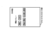
そこで、GUI情報出力部26は、図11のようなGUI画面を作成するためのGUI情報を出力し、デジタルI/F23がコントローラ27にこのGUI情報を送る。
Then, the GUI
コントローラ27は、図11のようなGUI画面をモニタ7に表示する。
(4) The
視聴者は、リモートコントローラ30の右36、左37を押して、「デジタル」、「アナログ」のいずれかにカーソルを移動させる。今「デジタル」にカーソルが移動しているとする。ここで、セレクト33を押すと「デジタル」が選択され、確定したことになる。 The viewer presses the right 36 and left 37 of the remote controller 30 to move the cursor to either “digital” or “analog”. Suppose now that the cursor is moving to “digital”. Here, pressing the select 33 selects "digital" and is confirmed.
リモートコントローラ30は、キーコードを送出し、コントローラ27は、キーコードを受信した後、D−VHS31に転送する。
(4) The remote controller 30 sends out the key code, and the
D−VHS31は、ターゲット22として、キーコードを受信する。キーコードは、デジタルI/F23からキーコード検出部24を経て、GUI情報出力部26に渡される。GUI情報出力部26は、図11の画面を作成するGUI情報がモニタ7に表示されていることをもとに送られてきたキーコードを解釈し、「デジタル」が選択確定したことを知る。GUI情報出力部26は、デジタル入力に切り替えるキーコードをデジタルI/F23に送り、デジタルI/F23は、このキーコードをキーコード検出部24に送る。
The D-
さらに、キーコード検出部24は、このキーコードを命令実行部25に送る。
{Furthermore, the key
命令実行部25は、デジタル入力に切り替える処理を実行する。
(4) The
このようにして、デジタル入力とアナログ入力を切り替える機能など、標準化されている機能ではなく、D−VHS31を製造しているメーカ独自の機能であっても、リモートコントローラ30から制御することが出来る。
In this manner, the remote controller 30 can control not only a standardized function such as a function of switching between digital input and analog input but also a function unique to the manufacturer of the D-
(第5の実施の形態)
次に、第5の実施の形態について説明する。
(Fifth embodiment)
Next, a fifth embodiment will be described.
本実施の形態では、標準化されている機能であるがリモートコントローラに実装できるキー数に制限があるため、リモートコントローラに対応するキーがないため直接操作出来ない機能を制御する場合について説明する。 In the present embodiment, a case will be described in which a function that cannot be directly operated because there is no key corresponding to the remote controller is limited because the number of keys that can be mounted on the remote controller is a standardized function.
本実施の形態の構成は第4の実施の形態と同一であるので記述を省略する。 構成 The configuration of the present embodiment is the same as that of the fourth embodiment, and a description thereof will be omitted.
次に、このような本実施の形態の動作を第4の実施の形態との相違点を中心に説明する。 Next, the operation of the present embodiment will be described focusing on differences from the fourth embodiment.
本実施の形態では、、視聴者がリモートコントローラ30を操作して、TV38の音声を主音声から副音声に切り替える動作について説明する。
In the present embodiment, an operation in which the viewer operates the remote controller 30 to switch the sound of the
そして、TV38の主音声と副音声を切り替える機能は、標準化されている機能ではあるが、リモートコントローラ30のキー数の制限により、リモートコントローラに対応するキーがないため直接操作出来ない機能であるとする。
The function of switching the main sound and the sub sound of the
視聴者は、リモートコントローラ30を操作して、TV38をリモートコントローラ30の制御の対象に切り替える。この動作は第1の実施の形態と同一である。
The viewer operates the remote controller 30 to switch the
そして、リモートコントローラ30のメニュー32を押す。
Then, the
そうすると、リモートコントローラ30はキーコードを送出し、キーコードは、コントローラ27のリモコン受信部16で受信された後、コード選択部15に渡される。
Then, the remote controller 30 sends out the key code, and the key code is received by the
コード選択部15は、このキーコードを、リモートコントローラ30のキーにない機能である拡張機能を呼び出す命令であると解釈する。すなわち、このキーコードをメニュー制御部28に送る。
The
メニュー制御部28は、標準化されているがリモートコントローラ30からは直接制御できない機能の一覧を記載したGUI情報を作成し、表示部14に出力する。
The
表示部14は、モニタ7にGUI情報をOSD出力する。
The
このようにして、モニタ7にはTV38を制御するための機能の一覧が表示される。
一 覧 In this way, a list of functions for controlling the
視聴者は、上34、下35、右36、左37のキーを操作して、「音声切り替え」の項目にカーソルを移動させる。ここで、セレクト33を押すと、「音声切り替え」の選択が確定する。 (4) The viewer operates the up 34, down 35, right 36, and left 37 keys to move the cursor to the item of "voice switching". Here, when the select 33 is pressed, the selection of “voice switching” is confirmed.
リモートコントローラ30は、キーコードをコントローラ27に送出し、コントローラ27は、このキーコードをリモコン受信部16から、コード選択部15を経て、メニュー制御部28に渡す。
The remote controller 30 sends the key code to the
メニュー制御部28は、現在出力しているGUI情報と、入力されたキーコードを解析し、選択されたのが「音声切り替え」の項目であることを知る。
(4) The
そこで、メニュー制御部28は、図12のようなGUI画面を作成するためのGUI情報を表示部14に出力する。
Then, the
表示部14は、図12のようなGUI画面をモニタ7に表示する。
The
視聴者は、リモートコントローラ30の右36、左37を押して、「主音声」から「副音声」にカーソルを移動させる。ここで、セレクト33を押すと「副音声」が選択され、確定したことになる。 The viewer presses the right 36 and left 37 of the remote controller 30 to move the cursor from “main sound” to “sub sound”. Here, when the select 33 is pressed, the “sub-audio” is selected and determined.
リモートコントローラ30は、キーコードを送出し、リモコン受信部16は、キーコードを受信する。コード選択部15は、キーコードをメニュー制御部28に送る。メニュー制御部28は、図12の画面を作成するGUI情報がモニタ7に表示されていることをもとに送られてきたキーコードを解釈し、「副音声」が選択されたことを知る。
(4) The remote controller 30 sends out the key code, and the remote
従って、メニュー制御部28は、副音声に切り替えるキーコードをデジタルI/F10に送る。
Therefore, the
デジタルI/F10は、このキーコードをTV38に送る。
The digital I /
第4の実施の形態と同様にして、TV38の命令実行部25は、音声を副音声に切り替える処理を行う。
命令 In the same manner as in the fourth embodiment, the
このようにして、主音声と副音声を切り替える機能など、標準化されているがリモートコントローラ30から直接操作できない機能については、コントローラ27が作成したGUI画面を操作することによって、コントローラ27が対応するキーコードを生成して、被制御機器に送ることによって、リモートコントローラ30から制御することが出来る。
In this manner, for functions that are standardized but cannot be directly operated from the remote controller 30, such as a function for switching between the main sound and the sub sound, the key corresponding to the key corresponding to the key by operating the GUI screen created by the
(第6の実施の形態)
次に、第6の実施の形態について説明する。
(Sixth embodiment)
Next, a sixth embodiment will be described.
本実施の形態では、リモートコントローラにキーはあるが、キーコードが標準化されていない機能をリモートコントローラで制御する場合について説明する。 In the present embodiment, a case will be described in which a function is provided with a key provided in the remote controller but a key code is not standardized by the remote controller.
本実施の形態の構成は、第4の実施の形態と、以下の点を除いて同一である。 構成 The configuration of the present embodiment is the same as the fourth embodiment except for the following points.
すなわち、図13に本実施の形態のコントローラ39を示す。コントローラ39は、第4の実施の形態のコントローラ27に加えて、キーコード対応表42を備えている。
FIG. 13 shows the
また、リモートコントローラ30の2画面41は2画面表示するためのキーである。 The two screens 41 of the remote controller 30 are keys for displaying two screens.
キーコード対応表42は、標準化されていない機能について各メーカが使用しているキーコードを対応つけた表であり、ICカードなどの半導体メモリに記録されているものである。 The key code correspondence table 42 is a table in which key codes used by manufacturers are associated with non-standardized functions, and are recorded in a semiconductor memory such as an IC card.
次に、このような本実施の形態の動作を説明する。 Next, the operation of the present embodiment will be described.
本実施の形態では、TV28を2画面表示する場合の動作を説明する。
In the present embodiment, an operation when the
なお、2画面表示する機能は、リモートコントローラ30に操作キーはあるが、キーコードは標準化されていない機能であるとする。 Note that the function of displaying two screens is a function in which the remote controller 30 has operation keys but key codes are not standardized.
コントローラ39は、標準化されていない機能について、メーカがどのようなキーコードを使用しているかを知るためのキーコード対応表42を保持している。キーコード対応表42は、コントローラ39を兼ねているSTB2を工場から出荷する時に予めICカードに記憶させておく。
The
またリモートコントローラ30を取り替えたために、キーの数やキーが表す機能が変更になった場合、新しいリモートコントローラに対応するキーコード対応表42をメーカのサービス店がICカードに記憶させることも出来る。 If the number of keys or the function represented by the key is changed due to the replacement of the remote controller 30, the service code store corresponding to the new remote controller can store the key code correspondence table 42 in the IC card.
今、TV38がリモートコントローラ30の制御の対象となっているとする。
と す る It is assumed that the
視聴者は、TV38を2画面表示するために、リモートコントローラ30の2画面41を押す。
The viewer presses the two screens 41 of the remote controller 30 to display the
そうすると、リモートコントローラ30は、2画面表示するキーコードを送出する。 Then, the remote controller 30 transmits a key code for displaying two screens.
コントローラ39のリモコン受信部16は、このキーコードを受信し、コード選択部15に渡す。
The remote
前述したように、2画面表示するためのキーコードは標準化されていない。すなわち、AというメーカとBというメーカで2画面表示するためのキーコードが異なっている。 キ ー As mentioned above, the key code for displaying two screens is not standardized. That is, the maker A and the maker B have different key codes for two-screen display.
コード選択部15は、デジタルI/F10にTV38のメーカを調べるよう命じる。
The
デジタルI/F10は、バス1を介してTV38のメーカを調べ、コード選択部15に通知する。TV28のメーカがAであったとする。
The digital I /
そうすると、コード選択部15は、キーコード対応表42から、Aというメーカの2画面表示のキーコード取り出し、他機器制御コードとしてデジタルI/F10に送る。
Then, the
デジタルI/F10は、このキーコードをTV38に送る。
The digital I /
TV38は、Aというメーカであり、送られてきたキーコードは自社のキーコードであるので、2画面切り替え処理を実行することが出来る。
The
このように、リモートコントローラ30にキーはあるが、キーコードが標準化されていない機能についても、被制御機器のメーカを調べ、そのメーカのキーコードを送ることによって、リモートコントローラ30で制御することが出来る。 As described above, even for a function in which the remote controller 30 has a key but a key code is not standardized, it is possible to control the remote controller 30 by checking the maker of the controlled device and transmitting the maker's key code. I can do it.
(第7の実施の形態)
次に、第7の実施の形態について説明する。
(Seventh embodiment)
Next, a seventh embodiment will be described.
本実施の形態では、リモートコントローラにキーはあるが、キーコードが標準化されていない機能をリモートコントローラで制御する場合について説明する。 In the present embodiment, a case will be described in which a function is provided with a key provided in the remote controller but a key code is not standardized by the remote controller.
本実施の形態の構成は、第6の実施の形態と同一である。 構成 The configuration of the present embodiment is the same as that of the sixth embodiment.
次に、このような本実施の形態の動作を第6の実施の形態との相違点に限って説明する。 Next, the operation of the present embodiment will be described only with respect to differences from the sixth embodiment.
本実施の形態でも、TV28を2画面表示する場合の動作を説明する。
で も Also in this embodiment, the operation when the
第6の実施の形態と同様にしてリモートコントローラ30は、2画面表示するキーコードを送出する。 (4) As in the sixth embodiment, the remote controller 30 sends a key code for displaying two screens.
コントローラ39のリモコン受信部16は、このキーコードを受信し、コード選択部15に渡す。
The remote
コード選択部15は、第6の実施の形態とは異なり、このキーコードをまずデジタルI/F10に送る。
Different from the sixth embodiment, the
デジタルI/F10は、このキーコードをTV38に転送する。
The digital I /
TV38は、このキーコードを受信する。たまたまこのキーコードがTV38のメーカと一致した場合は、TV38は2画面表示を実行することが出来る。
$
メーカが一致しないときは、TV38は、キーコードが送られてくるコマンドのベンダーユニークIDが自社のメーカでないので、キーコードを実行することが出来ないことをコントローラ29に通知する。
If the manufacturers do not match, the
コントローラ39のデジタルI/F10は、この通知を受信する。そしてデジタルI/F10は、コード選択部15にメーカが違うことを通知する。
(4) The digital I /
ここで、コード選択部15は、デジタルI/F10にTV38のメーカを調べるように命じる。
Here, the
これ以降の動作は第6の実施の形態と同様であるので、説明を省略する。 (4) The subsequent operation is the same as in the sixth embodiment, and a description thereof will not be repeated.
このように、リモートコントローラ30にキーはあるが、キーコードが標準化されていない機能についても、被制御機器のメーカを調べ、そのメーカのキーコードを送ることによって、リモートコントローラ30で制御することが出来る。 As described above, even for a function in which the remote controller 30 has a key but a key code is not standardized, it is possible to control the remote controller 30 by checking the maker of the controlled device and transmitting the maker's key code. I can do it.
(第8の実施の形態)
次に、第8の実施の形態について説明する。
(Eighth embodiment)
Next, an eighth embodiment will be described.
本実施の形態では、リモートコントローラにキーはあるが、キーコードが標準化されていない機能をリモートコントローラで制御する場合について説明する。 In the present embodiment, a case will be described in which a function is provided with a key provided in the remote controller but a key code is not standardized by the remote controller.
本実施の形態の構成は、第6の実施の形態と同一である。 構成 The configuration of the present embodiment is the same as that of the sixth embodiment.
次に、このような本実施の形態の動作を第6の実施の形態との相違点に限って説明する。 Next, the operation of the present embodiment will be described only with respect to differences from the sixth embodiment.
本実施の形態でも、TV28を2画面表示する場合の動作を説明する。
で も Also in this embodiment, the operation when the
第6の実施の形態と同様にしてリモートコントローラ30は、2画面表示するキーコードを送出する。 (4) As in the sixth embodiment, the remote controller 30 sends a key code for displaying two screens.
コントローラ39のリモコン受信部16は、このキーコードを受信し、コード選択部15に渡す。
The remote
コード選択部15は、このキーコードをまずデジタルI/F10に送る。
The
デジタルI/F10は、このキーコードをTV38に転送する。
The digital I /
TV38は、このキーコードを受信する。たまたまこのキーコードがTV38のメーカと一致した場合は、TV38は2画面表示を実行することが出来る。
$
メーカが一致しないときは、TV38は、キーコードが送られてくるコマンドのベンダーユニークIDが自社のメーカでないので、キーコードを実行することが出来ないことをコントローラ29に通知する。
If the manufacturers do not match, the
コントローラ39のデジタルI/F10は、この通知を受信する。そしてデジタルI/F10は、コード選択部15にメーカが違うことを通知する。
(4) The digital I /
そこで、コード選択部15は、キーコード対応表42から、別のメーカの2画面表示のキーコード取り出し、他機器制御コードとしてデジタルI/F10に送る。
Then, the
デジタルI/F10は、このキーコードをTV38に送る。
The digital I /
TV38は、送られてきたキーコードは自社のキーコードである場合、2画面切り替え処理を実行することが出来る。自社のキーコードでない場合は処理を実行することが出来ない。TV38は、2画面切り替えの処理が実行できたか出来なかったかをコントローラ39に通知する。
The
以下同様にして、コントローラ39、TV38が2画面切り替えが実行出来るまで、知っている限りのメーカの2画面切り替えのキーコードをTV38に送る。うまくいけば、TV38が2画面切り替えを実行出来る。
Similarly, the
このように、リモートコントローラ30にキーはあるが、キーコードが標準化されていない機能についても、コントローラ39が知っている限りのメーカのキーコードをTV38に手あたり次第送ることによって、リモートコントローラ30でTV38を制御することが出来る。
As described above, even if the remote controller 30 has a key but the key code is not standardized, the key code of the maker as long as the
(第9の実施の形態)
次に、第9の実施の形態について説明する。
(Ninth embodiment)
Next, a ninth embodiment will be described.
第1〜8の実施の形態では、リモートコントローラの制御の対象となっている機器は1台であった。これに対して、本実施の形態では、リモートコントローラがバスに接続されているすべての機器を同時に制御する場合について説明する。 In the first to eighth embodiments, the number of devices controlled by the remote controller is one. On the other hand, in the present embodiment, a case will be described in which the remote controller simultaneously controls all devices connected to the bus.
本実施の形態の構成は、第1の実施の形態と同一である。 構成 The configuration of the present embodiment is the same as that of the first embodiment.
ただし、バス構成記憶手段12は、第1の実施の形態と同様にバス1に接続されている機器の名称とノード番号を記憶することに加えて、電源オンオフなどバス1に接続している機器を一斉に制御する機能に関する状態をも記憶する。 However, the bus configuration storage means 12 stores the names and node numbers of the devices connected to the bus 1 as well as the devices connected to the bus 1 such as power on / off, as in the first embodiment. Also, the state relating to the function of simultaneously controlling is stored.
また、リモートコントローラ30には、第1の実施の形態で説明したキーに加えて、バス1に接続している全ての機器の電源を一斉にオンまたはオフにする全電源オン・オフキーがある。また、現在制御の対象となっている機器の電源をオンまたはオフにする電源オン・オフキーがある。ただし、本実施の形態の電源のオン・オフは、ターゲット22やコントローラ6以外の部分の電源をオン・オフするものであるとする。すなわち、STB2の電源をオフにすると、図3に示す部分の電源がオフになるだけで、図2のコントローラ6の機能は電源がオンになったままである。
The remote controller 30 has an all power on / off key for simultaneously turning on or off the power of all the devices connected to the bus 1 in addition to the keys described in the first embodiment. In addition, there is a power on / off key for turning on or off the power of the device currently being controlled. However, the turning on / off of the power supply in the present embodiment is to turn on / off the power of parts other than the
次に、このような本実施の形態の動作を第1の実施の形態との相違点を中心に説明する。 Next, the operation of the present embodiment will be described focusing on differences from the first embodiment.
リモートコントローラ30の電源オン・オフキーを押すことによって、第1の実施の形態と同様にして、現在制御の対象となっている機器の電源を入れたり、切ったりすることが出来る。 By pressing the power on / off key of the remote controller 30, it is possible to turn on / off the power of the device currently being controlled in the same manner as in the first embodiment.
このようにして、STB2とVTR1(3)の電源が入っているとする。そして、VTR2(4)とVTR3(4)の電源が切れているとする。 と す る It is assumed that STB2 and VTR1 (3) are powered on in this way. Then, it is assumed that the power of VTR2 (4) and VTR3 (4) is turned off.
ここで、ユーザがリモートコントローラ30の全電源オン・オフキーを押したとする。 Here, it is assumed that the user has pressed all power on / off keys of the remote controller 30.
そうすると、リモートコントローラ30は、全電源を入れるかまたは切るかを切り替える機能を指示するキーコードを送出する。 Then, the remote controller 30 sends out a key code for instructing a function of switching on / off all the power.
コントローラ6のリモコン受信部16は、このキーコードを受信し、コード選択部15に送る。
(4) The
コード選択部15は、このキーコードをデジタルI/F10に送る。
The
デジタルI/F10は、バス1に接続している全ての機器に電源が入っているかそれとも切れているかを問い合わせる。
(4) The digital I /
STB2とVTR1(3)は、この問い合わせを受けて、電源が入っているという答えを返す。 STB2 and VTR1 (3) receive this inquiry and return an answer that the power is on.
VTR2(4)とVTR3(5)は、この問い合わせを受けて、電源がきれているという答えを返す。 @ VTR2 (4) and VTR3 (5) receive this inquiry and return an answer that the power is off.
デジタルI/F10は、各機器から送られてきた答えをバス構成記憶手段12に記させる。すなわち、STB2とVTR1(3)は電源が入っており、VTR2(4)とVTR3(5)は電源が切れていることを記憶する。
(4) The digital I /
次に、デジタルI/F10は、電源が入っている機器に電源を切ることを指示するキーコードを送る。すなわち、STB2とVTR1にこのキーコードを送る。
Next, the digital I /
VTR1はこのキーコードを受信し、自らの電源を切る。 The VTR 1 receives this key code and turns off its power.
また、STB2については、デジタルI/F10が、このキーコードをコード選択部15に送り、コード選択部15は、命令実行部17にこのキーコードを送る。命令実行部17は、図3に示す部分の電源を切る。
For the
このようにして、リモートコントローラ30の全電源オン・オフキーを押すことによりバス1に接続している全ての電源を切ることが出来る。 In this way, all the power supplies connected to the bus 1 can be turned off by pressing all power on / off keys of the remote controller 30.
さらに、ユーザがリモートコントローラ30の全電源オン・オフキーをもう一度押したとする。 と す る Further, it is assumed that the user presses the all power on / off key of the remote controller 30 again.
そうすると、リモートコントローラ30は、全電源を入れるかまたは切るかを切り替える機能を指示するキーコードを送出する。 Then, the remote controller 30 sends out a key code for instructing a function of switching on / off all the power.
コントローラ6のリモコン受信部16は、このキーコードを受信し、コード選択部15に送る。
(4) The
コード選択部15は、このキーコードをデジタルI/F10に送る。
The
デジタルI/F10は、バス構成記憶手段12に記憶されている機器の状態を調べる。そして、バス1に接続している機器を一斉に電源切る前の状態を知る。すなわち、STB2とVTR1(3)は電源が入っていて、VTR2(4)とVTR3(5)は電源が切れていたことを知る。
The digital I /
次に、デジタルI/F10は、一斉に電源を切る前に電源が入っている機器に電源を入れることを指示するキーコードを送る。すなわち、STB2とVTR1にこのキーコードを送る。
Next, the digital I /
VTR1はこのキーコードを受信し、自らの電源を入れる。 $ The VTR 1 receives this key code and turns on its power.
また、STB2については、デジタルI/F10が、このキーコードをコード選択部15に送り、コード選択部15は、命令実行部17にこのキーコードを送る。命令実行部17は、図3に示す部分の電源を入れる。
{Digital I /
このようにして、リモートコントローラ30の全電源オン・オフキーを押すことによりバス1に接続している機器全ての電源を、一斉に電源を切る前の状態に復元することが出来る。 In this way, by pressing all power on / off keys of the remote controller 30, the power of all the devices connected to the bus 1 can be restored to the state before the power was turned off all at once.
このように、本実施の形態によればリモートコントローラ30の制御の対象となっている機器を意識しなくてもバス1に接続されている機器をリモートコントローラ30で制御することが出来る。 As described above, according to the present embodiment, the devices connected to the bus 1 can be controlled by the remote controller 30 without being conscious of the devices to be controlled by the remote controller 30.
また、バス1に接続している機器の電源を一斉に切ることが出来、また一斉に電源を切る前の状態にリモートコントローラ30の一回のキー操作で戻すことが出来るので、簡単に複数の機器を制御することが出来る。 In addition, since the power of the devices connected to the bus 1 can be turned off all at once, and the state before the power can be turned off all at once can be returned by one key operation of the remote controller 30, so that a plurality of devices can be easily operated. Equipment can be controlled.
(第10の実施の形態)
次に、第10の実施の形態について説明する。
(Tenth embodiment)
Next, a tenth embodiment will be described.
本実施の形態では、リモートコントローラから送られてくる指示を示すキーコードがバスに接続している機器のうち1台だけしかインプレメント(Implement)していない場合にその機器を自動的にリモートコントローラの制御の対象とする場合について説明する。 In the present embodiment, when only one of the devices connected to the bus has a key code indicating an instruction sent from the remote controller, the device is automatically controlled by the remote controller. Will be described.
本実施の形態の構成は、第1の実施の形態と同一である。 構成 The configuration of the present embodiment is the same as that of the first embodiment.
ただし、バス構成記憶手段12は、第1の実施の形態と同様にバス1に接続されている機器の名称とノード番号を記憶することに加えて、機器がインプレメントしている機能を表すキーコードの一覧をも記憶する。
However, the bus
また、リモートコントローラ30には、第1の実施の形態で説明したキーに加えて、音量を調節するボリュームキーがある。そして、音量を調節することが出来るのはSTB2のみであるとする。 The remote controller 30 has a volume key for adjusting the volume in addition to the keys described in the first embodiment. It is assumed that the volume can be adjusted only by STB2.
次に、このような本実施の形態の動作を第1の実施の形態との相違点を中心に説明する。 Next, the operation of the present embodiment will be described focusing on differences from the first embodiment.
リモートコントローラ30のボリュームキーを調節すると、リモートコントローラ30は、音量を上げるまたは下げる指示を示すキーコードを送出する。 When the volume key of the remote controller 30 is adjusted, the remote controller 30 sends out a key code indicating an instruction to increase or decrease the volume.
コントローラ6のリモコン受信部16は、このキーコードを受信し、コード選択部15に送る。
(4) The
コード選択部15は、このキーコードをデジタルI/F10に送る。
The
デジタルI/F10は、このキーコードをリモートコントローラ30の制御の対象となっている機器に転送する前に、バス構成記憶手段12を調べる。
The digital I /
そうすると、リモートコントローラ30の制御の対象となっている機器はこのキーコードに対応する機能をインプレメントしていないことが解る。さらに、STB2だけがこのキーコードをインプレメントしていることが解る。 Then, it is understood that the device controlled by the remote controller 30 does not implement the function corresponding to the key code. Further, it can be seen that only STB2 implements this key code.
デジタルI/F10は、このキーコードをコード選択部15に送る。
The digital I /
コード選択部15は、命令実行部17にこのキーコードを送る。命令実行部17は、音量を上げるまたは下げる処理を実行する。
The
このようにして、バス1に接続している機器のうち1台しかインプレメントしていない機能を指示するキーコードが、リモートコントローラ30から送られてきた場合には、自動的にその機能をインプレメントしている機器にキーコードを送る。 In this manner, when a key code indicating a function in which only one of the devices connected to the bus 1 is implemented is transmitted from the remote controller 30, the function is automatically implemented. Send the key code to the device that
このように、本実施の形態によればリモートコントローラ30の制御の対象となっている機器を意識しなくてもバス1に接続されている機器をリモートコントローラ30で制御することが出来る。 As described above, according to the present embodiment, the devices connected to the bus 1 can be controlled by the remote controller 30 without being conscious of the devices to be controlled by the remote controller 30.
(第11の実施の形態)
次に、第11の実施の形態について説明する。
(Eleventh embodiment)
Next, an eleventh embodiment will be described.
第4、5の実施の形態において、GUI情報を表示する必要が生じた場合、GUI情報をコントローラの機能を兼ねている機器に接続されているモニタに表示した。第4の実施の形態では、GUI情報を被制御機器が作成した。また第5の実施の形態ではGUI情報をコントローラ27が作成した。
In the fourth and fifth embodiments, when it is necessary to display GUI information, the GUI information is displayed on a monitor connected to a device that also functions as a controller. In the fourth embodiment, the GUI information is created by the controlled device. In the fifth embodiment, the GUI information is created by the
本実施の形態では、コントローラまたは被制御機器が作成したGUI情報をリモートコントローラに表示する場合について説明する。 In this embodiment, a case will be described in which GUI information created by a controller or a controlled device is displayed on a remote controller.
本実施の形態の構成は、第4の実施の形態のリモートコントローラ30を図14に示すリモートコントローラ43で置き換えた以外は、第4の実施の形態の構成と同一である。 構成 The configuration of the present embodiment is the same as the configuration of the fourth embodiment except that the remote controller 30 of the fourth embodiment is replaced with a remote controller 43 shown in FIG.
リモートコントローラ43は、操作面がタッチパネルになっており、操作面はGUI情報を表示するディスプレイを兼ねている。 The remote controller 43 has a touch panel on the operation surface, and the operation surface also serves as a display for displaying GUI information.
次に、このような本実施の形態の動作を説明する。 Next, the operation of the present embodiment will be described.
GUI情報は、コントローラ27などで作成されるかまたはリモートコントローラ43の制御の対象となっている機器で作成されるかいずれかである。
The GUI information is either created by the
GUI情報がコントローラ27で作成された場合は、コントローラ27は、そのGUI情報を保持する。
When the GUI information is created by the
また、GUI情報が被制御機器で作成された場合は、コントローラ27は、そのGUI情報を被制御機器から受け取り保持する。
If the GUI information is created by the controlled device, the
そして、GUI情報をリモートコントローラ43に送る。 送 る Then, the GUI information is sent to the remote controller 43.
リモートコントローラ43は、GUI情報を受け取る。 (4) The remote controller 43 receives the GUI information.
GUI情報は、画面のレイアウトを行い、キーとして機能する領域を定義し、キーとして機能する領域が指示された場合にどのようなキーコードを送出するかを記述したものである。 The $ GUI information lays out a screen, defines an area functioning as a key, and describes what key code is to be transmitted when the area functioning as a key is specified.
リモートコントローラ43は、自らのディスプレイにGUI画面を表示する。図14は、D−VHS31の再生を制御するGUI画面である。視聴者が例えば、表示されている再生キーをタッチすれば、GUI情報に定義されている再生に対応するキーコードがリモートコントローラ43から送出される。
(4) The remote controller 43 displays a GUI screen on its own display. FIG. 14 is a GUI screen for controlling the reproduction of the D-
コントローラ27は、リモートコントローラ43から送出されたキーコードを受信し、被制御機器であるD−VHS31に送る。
(4) The
このように本実施の形態によれば、GUI情報をリモートコントローラ43に表示させることが出来るので、家庭内のAVネットワークなどにおいて、コントローラ27とは別の部屋にある機器を制御する場合などモニタ7を見ることが出来なくても、リモートコントローラ43によって機器を制御することが出来る。
As described above, according to the present embodiment, the GUI information can be displayed on the remote controller 43. Therefore, in a home AV network or the like, the monitor 7 is used for controlling equipment in a room separate from the
(第12の実施の形態)
次に、第12の実施の形態について説明する。
(Twelfth embodiment)
Next, a twelfth embodiment will be described.
第4、5の実施の形態において、GUI情報を表示する必要が生じた場合、GUI情報をコントローラの機能を兼ねている機器に接続されているモニタに表示した。第4の実施の形態では、GUI情報を被制御機器が作成した。また第5の実施の形態ではGUI情報をコントローラ27が作成した。
In the fourth and fifth embodiments, when it is necessary to display GUI information, the GUI information is displayed on a monitor connected to a device that also functions as a controller. In the fourth embodiment, the GUI information is created by the controlled device. In the fifth embodiment, the GUI information is created by the
本実施の形態では、コントローラまたは被制御機器が作成したGUI情報をバスに接続している機器のモニタに表示する場合について説明する。 In this embodiment, a case will be described in which GUI information created by a controller or a controlled device is displayed on a monitor of a device connected to a bus.
本実施の形態の構成は、第4の実施の形態と同一である。 構成 The configuration of the present embodiment is the same as that of the fourth embodiment.
次に、このような本実施の形態の動作を説明する。 Next, the operation of the present embodiment will be described.
GUI情報はTV38のモニタに表示され、D−VHS31が被制御機器になっているとする。
It is assumed that the GUI information is displayed on the monitor of the
GUI情報は、コントローラ27などで作成されるかまたはリモートコントローラ30の制御の対象となっている機器で作成されるかいずれかである。
The GUI information is either created by the
GUI情報がコントローラ27で作成された場合は、コントローラ27は、そのGUI情報を保持する。
When the GUI information is created by the
また、GUI情報が被制御機器で作成された場合は、コントローラ27は、そのGUI情報を被制御機器から受け取り保持する。
If the GUI information is created by the controlled device, the
そして、GUI情報をTV38に送る。
送 る Then, send the GUI information to the
TV38は、GUI情報を受け取り自らのモニタに表示する。
The
GUI情報は、画面のレイアウトを行い、キーとして機能する領域を定義し、キーとして機能する領域が指示された場合にどのようなキーコードを送出するかを記述したものである。 The $ GUI information lays out a screen, defines an area functioning as a key, and describes what key code is to be transmitted when the area functioning as a key is specified.
コントローラ27は、リモートコントローラ30から送出されたキーコードを受信する。
The
このキーコードが被制御機器であるD−VHS31の機能を制御するキーコードである場合は、このキーコードをD−VHS31に送る。そして、D−VHS31は個のキーコードが指示する機能を実行する。
If this key code is a key code for controlling the function of the D-
このキーコードが被制御機器が作成したGUI情報の更新を指示するものである場合、コントローラ27は、このキーコードをD−VHS31に送る。そして、D−VHS31は、GUI情報を更新し、コントローラ27に送る。コントローラ27は更新されたGUI情報をTV38に送り、TV38は、更新されたGUI情報を表示する。
If the key code instructs updating of the GUI information created by the controlled device, the
このキーコードがコントローラ27が作成したGUI情報の更新を指示するものである場合、コントローラ27はGUI情報を更新し、更新したGUI情報をTV38に送る。TV38は、更新されたGUI情報を表示する。
(4) If the key code instructs to update the GUI information created by the
このように本実施の形態によれば、GUI情報をバス1に接続されている機器のモニタに表示することが出来る。 As described above, according to the present embodiment, GUI information can be displayed on a monitor of a device connected to the bus 1.
なお、本実施の形態のリモートコントローラの制御の対象となっている機器は本発明の被制御機器の例である。 The device controlled by the remote controller according to the present embodiment is an example of the controlled device of the present invention.
さらに、本発明のバス接続機器のリモコン制御システムのコントローラ、リモートコントローラ、被制御機器、バスに接続された複数個の機器の全部または一部の機能の全部または一部をハードウェアによって実現しても構わないし、コンピュータのプログラムを実行することによってソフトウェア的に実現しても構わない。 Further, all or some of the functions of all or some of the controllers, remote controllers, controlled devices, and a plurality of devices connected to the bus of the remote control control system for bus-connected devices of the present invention are implemented by hardware. Alternatively, it may be realized by software by executing a computer program.
さらに、本発明のバス接続機器のリモコン制御システムのコントローラ、リモートコントローラ、被制御機器、バスに接続された複数個の機器の全部または一部の、全部または一部の機能をコンピュータにより実行させるためのプログラムを記録したことを特徴とするプログラム記録媒体も本発明に属する。 Further, the present invention allows a computer to execute all or a part of functions of all or a part of a controller, a remote controller, a controlled apparatus, and a plurality of devices connected to a bus in a remote control system for a bus-connected device of the present invention. A program recording medium characterized by recording the above program also belongs to the present invention.
1 バス
2 STB
3 VTR1
4 VTR2
5 VTR3
6 コントローラ
7 モニタ7
10 デジタルI/F
11 転送先記憶手段
12 バス構成記憶手段
13 GUI情報取得部
14 表示部
15 コード選択部
16 リモコン受信部
17 命令実行部
22 ターゲット
23 デジタルI/F
24 キーコード検出部
25 命令実行部
26 GUI情報出力部
28 メニュー制御部
30 リモートコントローラ
31 D−VHS
32 メニュー
33 セレクト
34 上
35 下
36 右
37 左
38 TV
39 コントローラ
42 キーコード対応表
43 リモートコントローラ
50 コントローラ
51 デジタルI/F
1
3 VTR1
4 VTR2
5 VTR3
6 Controller 7 Monitor 7
10 Digital I / F
24 Key
32 Menu 33 Select 34 Upper 35 Lower 36 Right 37
39
Claims (5)
前記バスに接続された複数個の機器と、
前記複数個の機器のうちいずれか一つの機器を制御するリモートコントローラとを備え、
前記複数個の機器のうちいずれか一つの機器が、前記リモートコントローラによって制御されるコントローラとしての機能を有し、
前記複数個の機器のうち、全部または二つ以上の機器が前記リモートコントローラによって制御される被制御機器であり、
前記コントローラを兼ねる機器は、前記リモートコントローラからの指示を前記被制御機器に伝えるものであり、
前記コントローラは、前記リモートコントローラから送られてくる指示を表すキーコードを前記被制御機器に送ることを特徴とするバス接続機器のリモコン制御システム。 Bus and
A plurality of devices connected to the bus,
A remote controller for controlling any one of the plurality of devices,
Any one of the plurality of devices has a function as a controller controlled by the remote controller,
Among the plurality of devices, all or two or more devices are controlled devices controlled by the remote controller,
The device also serving as the controller is for transmitting an instruction from the remote controller to the controlled device,
The remote controller control system for a bus-connected device, wherein the controller sends a key code indicating an instruction sent from the remote controller to the controlled device.
前記コントローラが電源を切るキーコードを送る前に、前記コントローラは、各機器が電源が入っているか切れているかを調べておいて、前記電源を切るキーコードを電源が入っている前記機器に送って電源を切り、
その後、電源を入れる際に、前記調べておいた電源が入っていた機器のみ電源を入れるキーコードを送ることを特徴とする請求項2記載のバス接続機器のリモコン制御システム。 The key code is to turn on and off,
Before the controller sends a key code to turn off the power, the controller checks whether each device is turned on or off, and sends the key code to turn off the power to the device that is turned on. Power off,
3. The remote control system for a bus-connected device according to claim 2, wherein when the power is turned on, a key code for turning on the power is sent only to the device that has been turned on.
Priority Applications (1)
| Application Number | Priority Date | Filing Date | Title |
|---|---|---|---|
| JP2003325037A JP2004015831A (en) | 2003-09-17 | 2003-09-17 | Remote controller control system for devices connected to bus and program storage medium |
Applications Claiming Priority (1)
| Application Number | Priority Date | Filing Date | Title |
|---|---|---|---|
| JP2003325037A JP2004015831A (en) | 2003-09-17 | 2003-09-17 | Remote controller control system for devices connected to bus and program storage medium |
Related Parent Applications (1)
| Application Number | Title | Priority Date | Filing Date |
|---|---|---|---|
| JP32336599A Division JP3818804B2 (en) | 1999-11-12 | 1999-11-12 | Remote control system for bus connection device and program recording medium |
Publications (1)
| Publication Number | Publication Date |
|---|---|
| JP2004015831A true JP2004015831A (en) | 2004-01-15 |
Family
ID=30439072
Family Applications (1)
| Application Number | Title | Priority Date | Filing Date |
|---|---|---|---|
| JP2003325037A Pending JP2004015831A (en) | 2003-09-17 | 2003-09-17 | Remote controller control system for devices connected to bus and program storage medium |
Country Status (1)
| Country | Link |
|---|---|
| JP (1) | JP2004015831A (en) |
Cited By (2)
| Publication number | Priority date | Publication date | Assignee | Title |
|---|---|---|---|---|
| JP2008048137A (en) * | 2006-08-15 | 2008-02-28 | Sony Corp | Transmission system, video input apparatus and transmission method |
| US9442474B2 (en) | 2006-09-13 | 2016-09-13 | Savant Systems, Llc | Location-aware operation based on bluetooth positioning within a structure |
-
2003
- 2003-09-17 JP JP2003325037A patent/JP2004015831A/en active Pending
Cited By (3)
| Publication number | Priority date | Publication date | Assignee | Title |
|---|---|---|---|---|
| JP2008048137A (en) * | 2006-08-15 | 2008-02-28 | Sony Corp | Transmission system, video input apparatus and transmission method |
| US9442474B2 (en) | 2006-09-13 | 2016-09-13 | Savant Systems, Llc | Location-aware operation based on bluetooth positioning within a structure |
| US9541910B2 (en) | 2006-09-13 | 2017-01-10 | Savant Systems, Llc | Remote control unit for a programmable multimedia controller |
Similar Documents
| Publication | Publication Date | Title |
|---|---|---|
| US7554614B2 (en) | Remote control system | |
| US7386742B2 (en) | Method and apparatus for controlling power to a first and second circuit based on an operational mode and connecting state of an information processing apparatus | |
| US8732751B2 (en) | Audio video system, control apparatus, output apparatus, and program | |
| JP2008301298A (en) | Information input/output apparatus and information input/output method | |
| US11012733B2 (en) | Device controller, computer readable storage medium, and remote control system | |
| US20050120383A1 (en) | System for saving settings of an audiovisual system | |
| JP2008301232A (en) | Television receiving unit and apparatus control method | |
| JP2008085703A (en) | Display unit | |
| JP3818804B2 (en) | Remote control system for bus connection device and program recording medium | |
| JP2003018495A (en) | Digital broadcasting receiver and digital broadcasting reception method | |
| WO2012172850A1 (en) | Device operating system, display device, and operating device | |
| JP4774642B2 (en) | Device-to-device control apparatus and method | |
| KR101300949B1 (en) | Control method of external A/V devices connected to Display | |
| JP2009135846A (en) | Video display system | |
| JP2004015831A (en) | Remote controller control system for devices connected to bus and program storage medium | |
| JP2002281569A (en) | Remote control system, reproducing device, information storage device, reproduced data transmitting method and remote controller | |
| JP4013937B2 (en) | Digital television receiver connected to IEEE 1394 serial bus, and controller device connected to IEEE 1394 serial bus | |
| JP4143675B1 (en) | Remote control system and command transfer method | |
| JP5878559B2 (en) | Transmission device, reception device, and transmission / reception method | |
| KR101018483B1 (en) | Digital broadcasting receiver and digital device system | |
| JP2005340968A (en) | Av apparatus | |
| JP2008219932A (en) | Remote control system and command transfer method | |
| JP5294552B2 (en) | Video display device, recording / playback device | |
| JP2001309335A (en) | Video viewing system and video terminal device | |
| JP5736639B2 (en) | Recording equipment |