JP2004015143A - Hand-over method in mobile communication system and router used for the mobile communication system - Google Patents
Hand-over method in mobile communication system and router used for the mobile communication system Download PDFInfo
- Publication number
- JP2004015143A JP2004015143A JP2002162421A JP2002162421A JP2004015143A JP 2004015143 A JP2004015143 A JP 2004015143A JP 2002162421 A JP2002162421 A JP 2002162421A JP 2002162421 A JP2002162421 A JP 2002162421A JP 2004015143 A JP2004015143 A JP 2004015143A
- Authority
- JP
- Japan
- Prior art keywords
- router
- address
- mobile terminal
- router device
- packet
- Prior art date
- Legal status (The legal status is an assumption and is not a legal conclusion. Google has not performed a legal analysis and makes no representation as to the accuracy of the status listed.)
- Pending
Links
- 238000010295 mobile communication Methods 0.000 title claims abstract description 14
- 238000000034 method Methods 0.000 title claims description 135
- 238000004891 communication Methods 0.000 claims abstract description 94
- 230000005540 biological transmission Effects 0.000 claims description 4
- 238000012546 transfer Methods 0.000 abstract description 18
- 238000010586 diagram Methods 0.000 description 41
- 230000008569 process Effects 0.000 description 21
- 239000003795 chemical substances by application Substances 0.000 description 12
- 230000015654 memory Effects 0.000 description 11
- 230000003139 buffering effect Effects 0.000 description 10
- 230000004044 response Effects 0.000 description 10
- 238000012545 processing Methods 0.000 description 7
- 238000005516 engineering process Methods 0.000 description 4
- 230000002159 abnormal effect Effects 0.000 description 3
- 230000004913 activation Effects 0.000 description 3
- 230000005641 tunneling Effects 0.000 description 3
- 238000013459 approach Methods 0.000 description 2
- 238000007630 basic procedure Methods 0.000 description 2
- 230000006870 function Effects 0.000 description 2
- 230000009189 diving Effects 0.000 description 1
- 230000000694 effects Effects 0.000 description 1
- 239000002360 explosive Substances 0.000 description 1
- 238000009448 modified atmosphere packaging Methods 0.000 description 1
- 238000012544 monitoring process Methods 0.000 description 1
- 235000019837 monoammonium phosphate Nutrition 0.000 description 1
- 238000005457 optimization Methods 0.000 description 1
- 230000007704 transition Effects 0.000 description 1
Images


Classifications
-
- H—ELECTRICITY
- H04—ELECTRIC COMMUNICATION TECHNIQUE
- H04L—TRANSMISSION OF DIGITAL INFORMATION, e.g. TELEGRAPHIC COMMUNICATION
- H04L61/00—Network arrangements, protocols or services for addressing or naming
- H04L61/50—Address allocation
- H04L61/5084—Providing for device mobility
-
- H—ELECTRICITY
- H04—ELECTRIC COMMUNICATION TECHNIQUE
- H04W—WIRELESS COMMUNICATION NETWORKS
- H04W36/00—Hand-off or reselection arrangements
- H04W36/0005—Control or signalling for completing the hand-off
- H04W36/0011—Control or signalling for completing the hand-off for data sessions of end-to-end connection
- H04W36/0019—Control or signalling for completing the hand-off for data sessions of end-to-end connection adapted for mobile IP [MIP]
-
- H—ELECTRICITY
- H04—ELECTRIC COMMUNICATION TECHNIQUE
- H04W—WIRELESS COMMUNICATION NETWORKS
- H04W36/00—Hand-off or reselection arrangements
- H04W36/02—Buffering or recovering information during reselection ; Modification of the traffic flow during hand-off
-
- H—ELECTRICITY
- H04—ELECTRIC COMMUNICATION TECHNIQUE
- H04W—WIRELESS COMMUNICATION NETWORKS
- H04W80/00—Wireless network protocols or protocol adaptations to wireless operation
- H04W80/04—Network layer protocols, e.g. mobile IP [Internet Protocol]
-
- H—ELECTRICITY
- H04—ELECTRIC COMMUNICATION TECHNIQUE
- H04W—WIRELESS COMMUNICATION NETWORKS
- H04W88/00—Devices specially adapted for wireless communication networks, e.g. terminals, base stations or access point devices
- H04W88/005—Data network PoA devices
Abstract
Description
【0001】
【発明の属する技術分野】
本発明は、移動通信システムにおけるハンドオーバ方法および移動通信システムにおいて使用されるルータ装置に係わり、特に、移動通信サービスを提供するIPネットワークにおけるハンドオーバ方法およびそのためのルータ装置に係わる。
【0002】
【従来の技術】
近年、インターネット及び携帯電話の爆発的な普及により、モバイルユーザをインターネットに接続するアクセスシステムの多様化が進んできている。一例としては、現在では、GPRS(General Packet Radio System)やPDC−P(Personal Digital Cellular−mobilePacket communication system)等の第2世代移動通信網、UMTS(Universal Mobile TelecommunicationSystem)等の第3世代移動通信網、無線LAN、Bluetooth等の小規模無線アクセス網などが実用化されている。また、将来的には、第4世代移動通信網や他の新しい新しいアクセス技術が期待されている。そして、これらの技術により、1台の端末が複数のアクセスシステムと接続できるようになりつつあり、ユビキタス環境が視野にはいってきた。
【0003】
ところが、ユーザにとっては、アクセスシステムを意識しないでインターネットに接続できることが望ましい。ここで、このような環境を実現するためには、端末が自立的にアクセスシステムを選択または切替えできるようにするための技術が必要になってくる。そして、このための中核技術として、MobileIPが注目されている。
【0004】
なお、MobileIPは、IETF(Internet Engineering Task Force)により標準化されている。ここで、IETFのRFC2002において標準化されているMobileIPは、IPv4(RFC791)をベースにしている。ところが、近年、IPネットワーク上の端末数の増加に伴ってIPv4アドレスが不足してきており、IPv4からIPv6(RFC2460)への移行が進められつつある。そして、IPv6をベースにしたMobileIPv6は、インターネットドラフト(http://www.ietf.org/internet−drafts/draft−ietf−mobileip−ipv6−14.txt)として公開されており、近いうちに標準化される予定である。また、MobileIPv6の動作は、基本的には、MobileIPと同じである。従って、以下では、MobileIPv6について説明する。
【0005】
MobileIPv6では、一般に、各モバイル端末に対してホームアドレス及び気付けアドレス(CoA:Care of Address)が割り当てられる。ここで、ホームアドレスは、各モバイル端末に固定的に割り当てられるIPアドレスである。また、気付けアドレスは、モバイル端末を収容するアクセスルータ毎に、そのモバイル端末に対して割り当てられるIPアドレスである。そして、モバイル端末が移動した場合には、その移動に応じて動的に気付けアドレスがそのモバイル端末に割り当てられることによって、通信セッションが維持されるようになっている。
【0006】
ところが、MobileIPv6のハンドオーバは、一般に、遅延が大きい。ここで、遅延が大きくなる理由は、モバイル端末があるアクセスルータ(旧アクセスルータ)の通信エリアから、他のアクセスルータ(新アクセスルータ)の通信エリアに移動する際、モバイル端末が新アクセスルータの通信エリアへ移動した後にそれらの間で無線リンクを介してメッセージを交換することによりモバイル端末が新たな気付けアドレスを取得することに起因している。そして、通常、このときの無線パフォーマンスがハンドオーバ時間のネックとなっている。したがって、MobileIPv6は、インターネット電話やライブストリーミング等のUDP(RFC768)/RTP(RFC1889)上のリアルタイムアプリケーション、あるいは、TCP(RFC793)上の遅延に敏感なアプリケーションには適していないと考えられている。
【0007】
上記問題を解決する技術として、高速ハンドオーバ(Fast Handover)手順が提案されている。ここで、高速ハンドオーバ手順は、IETFによるインターネットドラフト(http://www.ietf.org/internet−drafts/draft−ietf−mobileip−fast−mipv6−04.txt)として公開されている。高速ハンドオーバ手順では、モバイル端末が旧アクセスルータの通信エリアから新アクセスルータの通信エリアへ移動する直前に、そのモバイル端末が、新アクセスルータの通信エリアにおいて使用する新気付けアドレスを取得する。そして、これにより、ハンドオーバ時に通信が出来なくなる時間が短縮される。
【0008】
次に、高速ハンドオーバの手順を説明する。なお、高速ハンドオーバ手順は、ネットワークが起動する方式と、モバイル端末が起動する方式とに分類することができる。また、高速ハンドオーバ手順は、ネットワークがアドレスを作成する方式(Stateful Address Autoconfiguration:http://www.ietf.org/internet−drafts/draft−ietf−dhc−dhcpv6−20.txt)と、モバイル端末がアドレスを作成する方式(StatelessAddress Autoconfiguration:RFC2462)とに分類することができる。そして、現在、下記の3種類の手順が定義されている。
(1)ネットワーク起動、Stateful
(2)ネットワーク起動、Stateless
(3)モバイル端末起動、Stateless
これら3つの方式の基本的な動作は互いに同じなので、以下では、上記(1)の方式の概要を示す。
【0009】
図22は、高速ハンドオーバ(Fast Handover)の基本手順を説明する図である。図23は、図22に示す処理のシーケンス図である。なお、ここでは、モバイル端末(MN:MobileNode)1が、旧アクセスルータ(AR)2の通信エリアから新アクセスルータ(AR)3の通信エリアに移動する場合を示す。また、モバイル端末1は、相手端末(CN:CorrespondentNode)4との間で通信を行っているものとする。さらに、モバイル端末1は、旧アクセスルータ2の通信エリアにおいて、「旧気付けアドレス」が割り当てられている。
【0010】
(1)相手端末4は、モバイル端末1の旧気付けアドレス宛てにパケットを送っている。このパケットは、旧アクセスルータ2により、モバイル端末1へ転送される。
【0011】
(2)モバイル端末1が新アクセスルータ3の通信エリアに接近すると、旧アクセスルータ2は、モバイル端末1のハンドオーバを予測し、新アクセスルータ3に対してモバイル端末1の新気付けアドレスを要求する。
【0012】
(3)新アクセスルータ3は、新気付けアドレスを作成し、それを旧アクセスルータ2に通知する。
(4)旧アクセスルータ2は、受信した新気付けアドレスをモバイル端末1に通知する。
【0013】
(5)モバイル端末1は、無線コネクションを切り換える直前に、旧アクセスルータ2に対して結合更新(Binding Update)メッセージを送信する。なお、この結合更新は、旧気付けアドレス宛てのパケットを新気付けアドレスへ転送するためのメッセージである。
【0014】
(6)旧アクセスルータ2は、結合更新メッセージを受信すると、そのメッセージに従って結合キャッシュを更新すると共に、応答メッセージを新気付けアドレスに送信する。これにより、新アクセスルータ3は上記応答メッセージを受け取る。なお、結合キャッシュには第1のIPアドレスおよび第2のIPアドレスを登録されており、ルータ装置は、第1のIPアドレス宛てのパケットを受信すると、第2のIPアドレスを用いてそのパケットをカプセル化して転送(トンネリング)する。
【0015】
(7)旧アクセスルータ2は、相手端末4から送出された旧気付けアドレス宛てのパケットを受信すると、そのパケットを新気付けアドレスへ転送する。
(8)新アクセスルータ3は、モバイル端末1との間のコネクションが確立されるまでの期間、新気付けアドレス宛てのパケットを保持する。
【0016】
(9)モバイル端末1は、無線コネクションを切り換える。すなわち、モバイル端末1は、新アクセルルータ3との間に無線コネクションを確立し、新気付けアドレスを通知する。
【0017】
(10)新アクセスルータ3は、モバイル端末1に対して応答メッセージを返送する。
(11)新アクセスルータ3は、上記手順8において保持してあるパケットをモバイル端末1へ送信する。
【0018】
(12)モバイル端末1は、MobileIPv6に基づいて、相手端末4(および、不図示のホームエージェント)に対して結合更新メッセージを送信する。なお、この結合更新は、ホームアドレス宛てのパケットを新気付けアドレスへ転送するためのメッセージである。
【0019】
(13)相手端末4は、上記結合更新メッセージを受け取ると、以降、新気付けアドレスへパケットを送信する。
このように、高速ハンドオーバ手順においては、モバイル端末1が、旧アクセスルータの通信エリアから新アクセスルータの通信エリアへ移動する前に、新気付けアドレスを取得するので、ハンドオーバによる遅延が小さくなる。
【0020】
【発明が解決しようとする課題】
しかし、既存の高速ハンドオーバ手順には、以下の3つの課題がある。
(1)非効率ルーティング
(2)パケットの順序逆転
(3)パケットロス
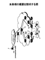
図24は、非効率ルーティングについて説明する図である。既存の高速ハンドオーバ手順においては、旧アクセスルータ2は、図22を参照しながら説明したように、モバイル端末1から結合更新メッセージを受信すると、以降は、相手端末4からモバイル端末1宛てのパケットを新アクセスルータ3へ転送する。このとき、旧アクセスルータ2から新アクセスルータ3へパケットを転送するルートは、図24に示すように、分岐点ルータ5を経由する。ここで、分岐点ルータ5は、相手端末4から旧アクセスルータ2へのルートと、相手端末4から新アクセスルータ3へのルートとが分岐するノードにおけるルータ装置を意味する。したがって、既存の高速ハンドオーバ手順では、モバイル端末1の移動に伴って、ネットワークに必要以上に大きな負荷がかかってしまう。なお、この問題は、階層化されたネットワークにおいて、しばしば、より大きな負荷を発生させることがある。
【0021】
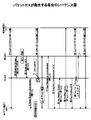
図25は、パケットの順序逆転について説明する図である。ここでは、相手端末4からモバイル端末1へ、パケットA、パケットB、パケットCが順番に送信されるものとする。また、相手端末4は、パケットBを送出した直後に、モバイル端末1から結合更新メッセージを受信したものとする。即ち、パケットA、Bは旧気付けアドレスへ送信され、パケットCは新気付けアドレスへ送信されたものとする。
【0022】
この場合、パケットA、Bは、いったん旧アクセスルータ2へ送られた後、分岐点ルータ5を介して新アクセスルータ3へ転送される。一方、パケットCは、直接的に新アクセスルータ3へ送られる。したがって、ネットワーク構成によっては、パケットA、Bよりも前に、パケットCがモバイル端末1へ到着してしまうことがある。
【0023】
なお、所定数(通常は、3)以上のパケットの順序逆転が発生すると、送信側のTCP(RFC2001)により再送処理が行われ、伝送速度が低下する。すなわち、TCPを利用する環境では、パケットの順序逆転によりスループットが低下することになる。また、UDP/RTP上のアプリケーションの場合は、パケットの順序逆転が発生すると、パケットが廃棄されることがある。すなわち、この場合、会話や動画像の瞬断が発生してしまう。
【0024】
図26は、パケットロスについて説明する図である。また、図27は、パケットロスが発生する場合のシーケンス図である。なお、図26および図27において、手順1〜手順4は、図22または図23を参照しながら説明した手順と同じである。ただし、図26および図27では、手順5においてモバイル端末1から送信された結合更新メッセージが旧アクセスルータ2へ到達できなかった場合を想定し、そのときの動作が示されている。なお、このような状況は、例えば、モバイル端末1とアクセスルータとの間の無線環境が劣悪な場合や、モバイル端末1が高速移動している場合などに発生し得る。
【0025】
(6)旧アクセスルータ2は、相手端末4から旧気付けアドレス宛てのパケットを受信する。しかし、旧アクセスルータ2は、モバイル端末1から結合更新メッセージを受信していないので、旧気付けアドレス宛てのパケットを新気付けアドレスへ転送できない。また、このとき、モバイル端末1は、すでに、旧アクセスルータ2の通信エリアから新アクセスルータ3の通信エリアへ移動してしまっている。したがって、受信パケットは、廃棄されてしまう。すなわち、パケットロスが発生する。
【0026】
(7)モバイル端末1は、無線コネクションを切り換える。すなわち、モバイル端末1は、新アクセルルータ3との間に無線コネクションを確立し、新気付けアドレスを通知する。
【0027】
(8)新アクセスルータ3は、モバイル端末1に対して応答メッセージを返送する。
(9)モバイル端末1は、旧アクセスルータ2へ結合更新メッセージを送信する。なお、なお、この結合更新は、旧気付けアドレス宛てのパケットを新気付けアドレスへ転送するためのメッセージである。
【0028】
(10)モバイル端末1は、通常のMobileIPv6に従い、相手端末4およびホームエージェントに対して結合更新メッセージを送信する。なお、この結合更新は、ホームアドレス宛てのパケットを新気付けアドレスへ転送するためのメッセージである。
【0029】
(11)旧アクセスルータ2は、手順9の結合更新メッセージに従って結合キャッシュを作成し、対応するメッセージをモバイル端末1に返送する。
(12)旧アクセスルータ2は、旧気付けアドレス宛てのパケットを受信すると、手順11で作成した結合キャッシュを参照し、そのパケットを新気付けアドレスへ転送する。
【0030】
(13)相手端末4は、手順10の結合更新メッセージに従って結合キャッシュを更新し、以降、新気付けアドレス宛てにパケットを送信する。
なお、上述のようなパケットロスが発生すると、通常、TCPがスロースタート動作を実行するので、スループットが低下してしまう。また、リアルタイムアプリケーションの場合は、会話や動画像の瞬断が発生することがある。
【0031】
このように、既存の高速ハンドオーバ手順では、非効率ルーティング、パケットの順序逆転、パケットロスなどが発生することがあった。
本発明の課題は、移動通信システムにおいて、既存のハンドオーバ手順の問題点を解決することである。すなわち、本発明の課題は、ハンドオーバ時に効率の悪いパケット転送が起こらないようにすることである。また、本発明の他の課題は、ハンドオーバ時にパケットロスまたはパケットの順序逆転が起こらないようにすることである。
【0032】
【課題を解決するための手段】
本発明のハンドオーバ方法は、第1のルータ装置の通信エリアにおいて第1のアドレスが割り当てられているモバイル端末がその第1のルータ装置の通信エリアから第2のルータ装置の通信エリアへ移動する際に、上記モバイル端末が上記第1のルータ装置を介して相手端末と通信を行っているときに、上記第2のルータ装置の通信エリアにおいて使用すべき第2のアドレスが上記モバイル端末に割り当てられ、上記第1のアドレス宛てのパケットを上記第2のアドレスへ転送させるためのメッセージが、上記相手端末から上記第1のルータ装置へのルートと上記相手端末から上記第2のルータ装置へのルートとが分岐するノードに位置する分岐点ルータ装置に送られる。
【0033】
上記方法によれば、モバイル端末のハンドオーバ時に、上記メッセージが分岐点ルータ装置に与えられる。したがって、相手端末から第1のアドレス宛てに送出されたパケットは、第1のルータ装置まで転送されることなく、分岐点ルータ装置により第2のルータ装置へ導かれる。即ち、ハンドオーバ時であっても、モバイル端末宛てのパケットは、効率的なルートを介して転送される。
【0034】
なお、上記方法において、上記第1および第2のルータ装置がゲートウェイの配下に設けられているものとすると、上記第1のルータ装置と上記ゲートウェイとの間に設けられているルータ装置と、上記第2のルータ装置と上記ゲートウェイとの間に設けられているルータ装置とを比較し、その比較において互いに一致するルータ装置を上記分岐点ルータ装置として指定するようにしてもよい。
【0035】
本発明の他の態様のハンドオーバ方法は、第1のルータ装置の通信エリアにおいて第1のアドレスが割り当てられているモバイル端末がその第1のルータ装置の通信エリアから第2のルータ装置の通信エリアへ移動する際に、上記モバイル端末が上記第1のルータ装置を介して相手端末と通信を行っているときに上記第2のルータ装置の通信エリアにおいて使用すべき第2のアドレスが上記モバイル端末に割り当てられ、上記モバイル端末に上記第2のアドレスが割り当てられたときから、上記第1のアドレス宛てのパケットを上記第2のアドレスへ転送させるためのメッセージが上記第1のルータ装置に与えられるまでの期間、上記第1のルータ装置において上記第1のアドレス宛てのパケットが蓄積され、上記メッセージが上記第2のルータ装置を介して上記第1のルータ装置に与えられたときに上記第1のルータ装置に蓄積されたパケットが上記第2のアドレスへ転送される。
【0036】
上記方法において、モバイル端末のハンドオーバ時に、そのモバイル端末宛てのパケットが第1のルータ装置にいったん蓄積される。一方、モバイル端末が第1のルータ装置の通信エリアから第2のルータ装置の通信エリアへ移動する際には、通常は、上記メッセージは、モバイル端末から第1のルータ装置へ直接的に送られる。しかし、第1のルータ装置とモバイル端末との間の通信環境が悪い場合などには、モバイル端末から第1のルータ装置へ上記メッセージを直接的に送ることはできず、第2のルータ装置の通信エリアへ移動した後にそのメッセージを第2のルータ装置を介して第1のルータ装置へ送ることになる。したがって、第1のルータ装置は、上記メッセージを上記第2のルータ装置を介して受信したときは、ハンドオーバ時にモバイル端末が受信すべきパケットがそのモバイル端末によって受信されていないものとみなし、蓄積してあるパケットをモバイル端末へ再送する。これにより、パケットのロスが回避される。
【0037】
なお、上記第2のルータ装置において、その第2のルータ装置と上記モバイル端末とが接続されるまでの間、そのモバイル端末宛てのパケットを蓄積し、上記相手端末における送信順序に従って上記蓄積されているパケットを読み出して上記モバイル端末へ送信するようにしてもよい。この方法によれば、ハンドオーバに際してモバイル端末宛てのパケットの順序が入れ替わった場合であっても、第2のルータ装置においてその順序が正しく並べ替えられる。
【0038】
【発明の実施の形態】
以下、本発明の実施形態について図面を参照しながら説明する。
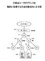
図1は、本発明の概要を説明する図である。なお、図1において、モバイル端末(MN:Mobile Node)1は、相手端末(CN:Correspondent Node)4と通信を行っている。また、モバイル端末1は、旧アクセスルータ11の通信エリアにおいて旧気付けアドレスが割り当てられている。更に、モバイル端末1は、新アクセスルータ12の通信エリアにおいては、新気付けアドレスが割り当てられるものとする。以下、既存の高速ハンドオーバ(FastHandover)において生じる3つの問題点を解決するための方策を示す。
(1)非効率ルーティングについて
本発明のハンドオーバ手順では、モバイル端末1が旧アクセスルータ(第1のルータ装置)11の通信エリアから新アクセスルータ(第2のルータ装置)12の通信エリアへ移動する際に、モバイル端末1から旧アクセスルータ11へ結合更新メッセージが送られる。ここで、この結合更新は、旧気付けアドレス宛てのパケットを新気付けアドレスへ転送するためのメッセージである。そして、旧アクセスルータ11は、モバイル端末1から結合更新メッセージを受信すると、そのメッセージを分岐点ルータ(DPR:Diverging Point Router)13へ送る。尚、分岐点ルータ13は、相手端末4から旧アクセスルータ11へのルートと、相手端末4から新アクセスルータ12へのルートとが分岐するノードにおけるルータ装置を意味する。あるいは、分岐点ルータ13は、ドメインゲートウェイから旧アクセスルータ11へのルートと、そのドメインゲートウェイから新アクセスルータ12へのルートとが分岐するノードにおけるルータ装置を意味する。
【0039】
分岐点ルータ13は、上記結合更新メッセージを受信した後は、モバイル端末1に割り当てられていた旧気付けアドレス宛てのパケットを受信すると、そのパケットをモバイル端末1に新たに割り当てられた新気付けアドレスへ転送(トンネリング)する。したがって、本発明の手順によれば、ハンドオーバ時にパケットがいったん旧アクセスルータ11に送られた後にモバイル端末1へ転送されるような非効率ルーティング(図24参照)が回避される。
(2)パケットの順序逆転について
新アクセスルータ12は、モバイル端末1のハンドオーバ時に、一定期間、モバイル端末1宛てのパケットをバッファに蓄積する。そして、モバイル端末1と新アクセスルータ12との間にコネクションが確立すると、新アクセスルータ12は、そのバッファに蓄積してあるパケットをモバイル端末1へ送信する。このとき、パケットが正しい順序でモバイル端末1に送信されるように、バッファからのパケットの読出しが適切に制御される。これにより、パケットの順序逆転の問題が解決される。
【0040】
なお、パケットの順序は、既存のバッファ管理アルゴリズムを利用して適切に並べ替えることが可能である。具体的には、例えば、各パケットのTCPヘッダまたはRTPヘッダに設定されているシーケンス番号を利用ことにより順序管理を実現することができる。
(3)パケットロスについて
旧アクセスルータ11は、新アクセスルータ12から取得した新気付けアドレスをモバイル端末1に通知すると、以降、モバイル端末1宛てのパケットを受信したときには、それをモバイル端末1へ送ると共に、それをコピーしてバッファに保持する。そして、旧アクセスルータ11は、モバイル端末1から結合更新メッセージを受信するまで、パケットを蓄積する動作を続ける。なお、ステイトレス・アドレス・コンフィグレーションの場合は、旧アクセスルータ11は、新アクセスルータ12のプレフィックスをモバイル端末1に通知したときから、上記パケットの蓄積を開始する。
【0041】
この後、旧アクセスルータ11は、モバイル端末1から結合更新メッセージを受信する。このとき、旧アクセスルータ11は、アクセスルータの切替えが行われる前に結合更新メッセージを受信した場合には、その時点までのパケットはすべてモバイル端末1によって受信されているものとみなし、バッファに蓄積してあるパケットを廃棄する。一方、旧アクセスルータ11は、アクセスルータの切替えが行われた後に結合更新メッセージを受信した場合には、その時点までに蓄積したパケットをモバイル端末1に転送し、以降のバッファリング処理を停止する。
【0042】
このように、本発明の手順においては、モバイル端末1が新アクセスルータ12の通信エリアへ移動する前に旧アクセスルータ11が結合更新メッセージを受信できなかった場合には、旧アクセスルータ11に保持されているパケットがモバイル端末1へ再送されるので、パケットの廃棄が回避される。
【0043】
次に、本発明の実施形態について詳しく説明する。
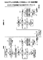
図2は、本発明の実施形態のハンドオーバ手順(正常動作時)を説明する図である。また、図3は、図2に示す動作に対応するシーケンス図である。
【0044】
モバイル端末1は、例えば携帯電話端末であり、キャリア網との間で無線信号を送受信する機能を備えている。なお、モバイル端末1は、携帯電話端末に限定されるものではなく、他の形態の端末装置(例えば、PDA、パーソナルコンピュータ等)であってもよい。
【0045】
キャリア網は、複数のルータ装置を備える。ここで、各ルータ装置は、それぞれ、パケットをその宛先アドレスに従ってルーティングする機能を備えている。一方、モバイル端末1は、それら複数のルータ装置の中のいずれかのルータ装置に接続する。そして、モバイル端末1から送出されたパケットは、これらのルータ装置を経由して宛先へ転送される。このとき、モバイル端末1から送出されたパケットを最初に処理するルータ装置が「アクセスルータ」と呼ばれる。また、モバイル端末1宛てのパケットは、そのモバイル端末1が接続しているアクセスルータへ転送され、そのアクセスルータからモバイル端末1へ送られる。
【0046】
上記移動通信ネットワークにおいて、モバイル端末1が移動すると、対応するアクセスルータが切り替わる。例えば、モバイル端末1が第1のルータ装置の通信エリアから第2のルータ装置通信エリアに移動したときは、このモバイル端末1に対応するアクセスルータは、第1のルータ装置(旧アクセスルータ11)から第2のルータ装置(新アクセスルータ12)に切り替わる。
【0047】
分岐点ルータ13は、相手端末4から旧アクセスルータ11へのルートと、相手端末4から新アクセスルータ12へのルートとが分岐するノードにおけるルータ装置を意味する。たとえば、図4において、モバイル端末1がルータ装置23の通信エリアからルータ装置24の通信エリアへ移動した場合を考える。この場合、相手端末4からルータ装置23へ至るルートと、相手端末4からルータ装置24へ至るルートとは、ルータ装置22において分岐されることになる。したがって、この場合、ルータ装置22が分岐点ルータになる。同様に、モバイル端末1がルータ装置24の通信エリアからルータ装置25の通信エリアへ移動した場合には、ルータ装置21が分岐点ルータになる。
【0048】
上記移動通信ネットワークにおいて、モバイル端末1が、旧アクセスルータ11の通信エリアから新アクセスルータ12の通信エリアへ移動するものとする。すなわち、モバイル端末1が旧アクセスルータ11に接続する状態から、モバイル端末1が新アクセスルータ12に接続する状態へのハンドオーバが発生するものとする。また、モバイル端末1は、相手端末4との間で通信を行っているものとする。さらに、モバイル端末1は、旧アクセスルータ11の通信エリアにおいて、「旧気付けアドレス」が割り当てられているものとする。
【0049】
この場合のハンドオーバ手順は、以下の通りである。なお、以下の説明では、ステイトフル・アドレス・オートコンフィグレーションを前提とする。
(1)通信相手4は、モバイル端末1の旧気付けアドレス宛てにパケットを送っている。このパケットは、旧アクセスルータ11へ転送され、さらに旧アクセスルータ11からモバイル端末1へ転送される。
【0050】
(2)モバイル端末1が新アクセスルータ12の通信エリアに接近すると、旧アクセスルータ11は、モバイル端末1のハンドオーバを予測し、新アクセスルータ12に対してハンドオーバ起動(Handover Initiate)メッセージを送る。このハンドオーバ起動メッセージは、モバイル端末1の新気付けアドレスを要求するメッセージであり、図5に示すフォーマットを有する。
【0051】
ハンドオーバ起動メッセージのフォーマットは、公知であり、タイプ領域、コード領域、チェックサム領域、識別子領域、Sビット、Uビット、Hビット、Tビット、Rビット、オプション領域を備える。ただし、本実施形態のシステムでは、IビットおよびDビットが新たに定義されている。ここで、Iビットは、蓄積されているパケットをバッファ管理アルゴリズムに従って正しく並べ替えることを要求する際に使用される。また、Dビットは、新アクセスルータとドメインゲートウェアとの間に位置するルータ装置のIPアドレスを要求する際に使用される。
【0052】
なお、手順2において、ハンドオーバ起動メッセージのUビットには「1」が設定される。ここで、「Uビット=1」は、パケットの蓄積の要求を意味する。また、Iビットにも「1」が設定される。ここで、「Iビット=1」は、パケット順序の解決の要求を意味する。
【0053】
(3)新アクセスルータ12は、モバイル端末1のための新気付けアドレスを作成する。このとき、新アクセスルータ12は、ネイバー・キャッシュに新気付けアドレスのためのエントリを作成し、そのエントリの状態を「INCOMPLETE」にする。なお、「INCOMPLETE」は、ハンドオーバ処理が未完了であることを表示する。そして、新アクセスルータ12は、ハンドオーバ起動メッセージに対応するハンドオーバ応答(Handover Acknowledgement)メッセージを利用して、新気付けアドレスを旧アクセスルータ11に通知する。尚、ネイバー・キャッシュは、RFC2461に定義されている。
【0054】
(4)旧アクセスルータ11は、Proxy Router Advertisementメッセージを利用して、新気付けアドレスをモバイル端末1に通知する。このとき、旧アクセスルータ11は、障害をモニタするためのタイマを起動する。また、旧アクセスルータ11は、旧気付けアドレス宛てのパケットをモバイル端末1へ転送する際に、そのパケットをコピーしてバッファに蓄積する処理を開始する。なお、旧アクセスルータ11におけるバッファ処理については、後で詳しく説明する。
【0055】
(5)モバイル端末1は、無線コネクションを切り換える直前に、旧アクセスルータ11に対して結合更新(Fast Binding Update)メッセージを送る。なお、この結合更新は、旧気付けアドレス宛てのパケットを新気付けアドレスへ転送するためのメッセージである。また、このメッセージの送信元アドレスは、モバイル端末1の旧気付けアドレスである。
【0056】
(6)旧アクセスルータ11は、結合更新メッセージを受信すると、そのメッセージに従って結合キャッシュを更新する。このとき、このメッセージの送信元アドレスをチェックする。そして、この送信元アドレスが旧気付けアドレスであったときは、旧アクセスルータ11は、モバイル端末1が旧アクセスルータ11の通信エリア内から送信した結合更新メッセージを受信したものと判断する。すなわち、正常動作が行われていると判断する。ここでは、旧アクセスルータ11は、手順5において送信された結合更新メッセージを受信するので、正常動作が行われているものと判断する。
【0057】
この場合、旧アクセスルータ11は、パケットをコピーする処理を停止すると共に、バッファに蓄積されているパケットを廃棄する。また、上記タイマはリセットされる。
【0058】
さらに、旧アクセスルータ11は、分岐点ルータ13に対して結合更新メッセージを送る。ここで、この結合更新は、旧気付けアドレス宛てのパケットを新気付けアドレスへ転送するためのメッセージである。なお、分岐点ルータ13を特定する処理は、後で詳しく説明する。
【0059】
(7)旧アクセスルータ11は、手順5の結合更新メッセージに対応する結合応答(Fast Binding Acknowledgement)メッセージを、モバイル端末1の新気付けアドレスに返送する。これにより、新アクセスルータ12はこの結合応答メッセージを受け取る。
【0060】
(8)分岐点ルータ13は、手順6の結合更新メッセージに従って、結合キャッシュに新たなエントリを作成する。ここで、このエントリには、モバイル端末1の旧気付けアドレス宛てのパケットをモバイル端末1の新気付けアドレスへトンネリングするための情報が登録される。したがって、分岐点ルータ13は、相手端末4からモバイル端末1の旧気付けアドレス宛てのパケットを受信すると、そのパケットをモバイル端末1の新気付けアドレスへトンネリングする。すなわち、旧気付けアドレス宛てのパケットは、旧アクセスルータ11に転送されることなく、新アクセスルータ12へ送られることになる。
【0061】
(9)新アクセルルータ12は、新気付けアドレス宛てのパケットを受信すると、ネイバーキャッシュを参照してそのアドレスの状態をチェックする。ここでは、新気付けアドレスの状態は、「INCOMPLETE」である。従って、新アクセスルータ12は、新気付けアドレス宛てのパケットをバッファに蓄積していく。そして、バッファに蓄積されているパケットを、各パケットのTCPヘッダに書き込まれているシーケンス番号に従って並べ替える。したがって、図25を参照しながら説明したパケットの順序逆転の問題は回避される。なお、この順序制御処理は、手順2のハンドオーバ起動メッセージのIビットに「1」が設定されていた場合にのみ実行される。また、この順序制御処理については、後で詳しく説明する。
【0062】
(10)モバイル端末1は、新アクセルルータ12の通信エリアに入ると、アクセスルータ12との間に新たな無線コネクションを確立する。そして、モバイル端末1は、その無線コネクションを介して、Fast Neighbour Advertisementメッセージを新アクセスルータ12へ送る。
【0063】
(11)新アクセスルータ12は、ネイバーキャッシュに登録されている新気付けアドレスの状態を「INCOMPLETE」から「REACHABLE」に変更する。そして、手順10のFast Neighbour Advertisementメッセージに対応するNeighbour Advertisement ACKメッセージを、モバイル端末1に返送する。
【0064】
(12)新アクセスルータ12は、バッファに蓄積してあるパケットをモバイル端末1の新気付けアドレスへ送る。
(13)モバイル端末1は、MobileIPv6に基づいて、相手端末4(および、不図示のホームエージェント)に対して結合更新メッセージを送信する。なお、この結合更新は、ホームアドレス宛てのパケットを新気付けアドレスへ転送するためのメッセージである。
【0065】
(14)相手端末4は、上記結合更新メッセージを受け取ると、以降、新気付けアドレスへパケットを送信する。
このように、実施形態の手順においては、手順6において分岐点ルータ13へ結合更新メッセージを送ることにより、図24を参照しながら説明した非効率ルーティングの問題が解決される。また、新アクセスルータ12においてパケットの並替えが行われるので、図25を参照しながら説明したパケットの順序逆転の問題は回避される。
【0066】
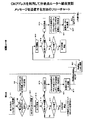
図6は、本発明の実施形態のハンドオーバ手順(非正常動作時)を説明する図である。また、図7は、図6に示す動作に対応するシーケンス図である。なお、ここでは、図2を参照しながら説明した手順5において、モバイル端末1から送出された結合更新メッセージが、何らかの理由により、旧アクセスルータ11に到達できなかった場合を想定する。このような状況は、例えば、モバイル端末1と旧アクセスルータ11との間の無線環境が劣悪な場合、あるいはモバイル端末1が高速で移動している場合などの発生し得る。
【0067】
手順1〜4では、図2を参照しながら説明した通り、モバイル端末1に新気付けアドレスが割り当てられる。また、旧アクセスルータ11は、モバイル端末1の旧気付けアドレス宛てのパケットをバッファに蓄積する。以下、手順6以降について説明する。
【0068】
(6)旧アクセスルータ11は、モバイル端末1の旧気付けアドレス宛てのパケットを蓄積する動作を継続する。
(7)モバイル端末1は、新アクセルルータ12の通信エリアに入ると、新アクセスルータ12との間に新たな無線コネクションを確立する。そして、モバイル端末1は、その無線コネクションを介して、Fast Neighbour Advertisementメッセージを新アクセスルータ12へ送る。なお、この動作は、図2における手順10と同じである。
【0069】
(8)新アクセスルータ12は、ネイバーキャッシュに登録されている新気付けアドレスの状態を「INCOMPLETE」から「REACHABLE」に変更する。そして、受信したFast Neighbour Advertisementメッセージに対応するNeighbour Advertisement ACKメッセージを、モバイル端末1に返送する。なお、この動作は、図2における手順11と同じである。
【0070】
(9)モバイル端末1は、旧アクセスルータ11に対して、再度、結合更新メッセージを送る。ここで、この結合更新も、旧気付けアドレス宛てのパケットを新気付けアドレスへ転送するためのメッセージである。ただし、このメッセージの送信元アドレスは、モバイル端末1の新気付けアドレスである。
【0071】
(10)モバイル端末1は、MobileIPv6に基づいて、相手端末4(および、不図示のホームエージェント)に対して結合更新メッセージを送信する。ここで、この結合更新は、ホームアドレス宛てのパケットを新気付けアドレスへ転送するためのメッセージである。なお、この動作は、図2における手順12と同じである。
【0072】
(11)旧アクセスルータ11は、手順9においてモバイル端末1から送出された結合更新メッセージを受信すると、そのメッセージに従って結合キャッシュを更新する。このとき、このメッセージの送信元アドレスをチェックする。ここでは、このメッセージの送信元アドレスは、新気付けアドレスである。したがって、旧アクセスルータ11は、モバイル端末1が新アクセスルータ12の通信エリアから送信され結合更新メッセージを受信したものと判断する。すなわち、非正常動作が行われていると判断する。
【0073】
この場合、旧アクセスルータ11は、バッファに蓄積されている旧気付けアドレス宛てのパケットを、通常のMobileIPv6に従って、新気付けアドレスへトンネリングする。そして、パケットをコピーしてバッファに蓄積する処理を停止すると共に、タイマをリセットする。
【0074】
(12)相手端末4は、手順10の結合更新メッセージを受け取ると、以降、新気付けアドレスへパケットを送信する。
このように、実施形態のハンドオーバ方法においては、旧アクセスルータ11が手順5の結合更新メッセージを受信できなかったときは、旧アクセスルータ11からモバイル端末1へ新気付けアドレスが通知されたときから、新アクセスルータ12を介して結合更新メッセージを受信するまでの間、モバイル端末1の旧気付けアドレス宛てのパケットが旧アクセスルータ11に蓄積される。そして、旧アクセスルータ11は、新アクセスルータ12を介して結合更新メッセージを受信すると、その蓄積してあるパケットをモバイル端末1の新気付けアドレスに送信する。したがって、パケットのロスが回避される。
【0075】
一例を示す。ここでは、図8に示すように、モバイル端末1の旧気付けアドレス宛てにパケット1〜4が送信されるものとする。この場合、旧アクセスルータ11は、これらのパケットをモバイル端末1の旧気付けアドレスへ転送する。また、旧アクセスルータ11は、パケット1、2をモバイル端末1へ転送した時点で、モバイル端末1へ新気付けアドレスを通知したとする。この場合、パケット3、4は、バッファに格納される。
【0076】
この後、モバイル端末1は、パケット3、4を受信することなく、新アクセスルータ12の通信エリアへ移動したものとする。また、モバイル端末1から送出された結合更新メッセージは、旧アクセスルータ11には到達したかったものとする。この場合、旧アクセスルータ11は、モバイル端末から送出された結合更新メッセージを新アクセスルータ12を介して受信すると、バッファに蓄積されているパケット3、4を、モバイル端末1の新気付けアドレスへ送信する。そして、モバイル端末1は、新アクセスルータ12を介してパケット3、4を受信する。これにより、モバイル端末1は、パケット1〜4を受信することができる。すなわち、パケットロスの発生が回避される。
【0077】
次に、旧アクセスルータ11が結合更新メッセージを送るために分岐点ルータ13を特定する方法を説明する。ここでは、以下の4つのケースを示す。
(1)分岐点ルータのアドレスが予め定義されている場合
(2)分岐点ルータのアドレスを動的に取得する場合
(3)分岐点ルータのアドレスを取得できない場合(MACアドレス利用)
(4)分岐点ルータのアドレスを取得できない場合(CNアドレス利用)
(1)分岐点ルータのアドレスが予め定義されている場合
この場合、各ルータ装置に、それぞれ、モバイル端末1の移動先と、その移動先に対応する分岐点ルータとが関連づけられて登録されている。例えば、図4に示すルータ装置24には、「移動先:ルータ装置23」と「分岐点:ルータ装置22」とが関連づけて登録されており、「移動先:ルータ装置25」と「分岐点:ルータ装置21」とが関連づけて登録されている。したがって、例えば、モバイル端末1が、ルータ装置24の通信エリアからルータ装置23の通信エリアへ移動する際には、分岐点ルータとして「ルータ装置22」が特定される。また、モバイル端末1が、ルータ装置24の通信エリアからルータ装置25の通信エリアへ移動する際には、分岐点ルータとして「ルータ装置21」が特定される。そして、特定された分岐点ルータに対して結合更新メッセージが送られる。なお、上記対応関係を表す情報は、例えば、ネットワークの構築時に各ルータ装置に設定されるようにしてもよい。
【0078】
(2)分岐点ルータのアドレスを動的に取得する場合
この場合、各ルータ装置は、ドメインゲートウェイ20のアドレスを知っているものとする。また、各ルータ装置は、自分自身とドメインゲートウェイとの間に存在する各ルータ装置のIPアドレスを知っているものとする。なお、これらのルータ装置のIPアドレスは、例えば、トレース・ルート(Traceroute)により取得することができる。
【0079】
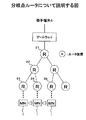
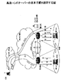
図9は、分岐点ルータのアドレスを動的に取得する方法を模式的に示す図である。ここでは、ルータ装置21〜26に割り当てられているIPアドレスが、それぞれ、「aaaa」〜「ffff」であるものとする。また、当該ドメインをインターネットに接続するためのゲートウェイ20のアドレスが「GGGG」であるものとする。そして、各ルータ装置は、自分自身とゲートウェイ20との間に設けられているルータ装置のアドレスを管理している。図9においては、ルータ装置24が備えるルータ管理リスト24aには、ルータ装置22、ルータ装置21、ゲートウェイ20のアドレスが順番に登録されている。一方、ルータ装置25が備えるルータ管理リスト25aには、ルータ装置26、ルータ装置21、ゲートウェイ20のアドレスが順番に登録されている。
【0080】
上記ネットワークにおいて、モバイル端末1がルータ装置24の通信エリアからルータ装置25の通信エリアへ移動すると、ルータ装置(旧アクセスルータ)24は、ルータ装置(新アクセスルータ)25に対して、ルータ管理リスト25aの転送を要求する。そして、ルータ管理リスト24aとルータ管理リスト25aとを比較し、互いに一致するアドレスを探す。この実施例では、双方のリストに「aaaa」が登録されている。よって、この場合、ルータ装置21が分岐点ルータであると判断される。なお、上述のようにしてリストを比較したときに、複数のアドレスが一致した場合には、例えば、旧アクセスルータに最も近いルータ装置が分岐点ルータと判断される。
【0081】
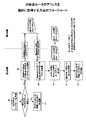
図10は、分岐点ルータのアドレスを動的に取得する方法のフローチャートである。なお、このフローチャートの処理は、旧アクセスルータ11により実行される。
【0082】
ステップS1では、モバイル端末1の位置およびその移動方向に基づいて、ハンドオーバの発生を予測する。このとき、新アクセスルータ12が特定される。なお、新アクセスルータ12を予測する方法は、公知の技術である。
【0083】
ステップS2では、旧アクセスルータ11と新アクセスルータ12との組合せに対応する分岐点ルータのIPアドレスが予めあるいは既に登録されているか否かを調べる。そして、分岐点ルータのIPアドレスが登録されていれば、ステップS3において、モバイル端末1から受信した結合更新メッセージをその分岐点ルータを送る。一方、分岐点ルータのIPアドレスが登録されていなければ、ステップS4以降の処理が実行される。
【0084】
ステップS4では、ハンドオーバ起動(Handover Initiate)メッセージを利用して、新アクセスルータ12に対して、新アクセスルータ12とドメインゲートウェイとの間に設けられているルータ装置のアドレスを要求する。このとき、このハンドオーバ起動メッセージは、図5に示したDビットに「1」が設定される。そして、新アクセスルータ12は、Dビットに「1」が設定されたハンドオーバ起動メッセージを受信すると、ハンドオーバ応答(HandoverACK)メッセージを利用して、図9に示したルータ管理リストを旧アクセスルータ11へ送信する。
【0085】
図11は、ハンドオーバ応答(Handover ACK)メッセージのフォーマットを示す図である。このメッセージは、アドレスを通知するために利用される。具体的には、サブタイプ(Sub−Type)として「1」が設定されているときは、アドレス領域に旧気付けアドレスが書き込まれ、「2」が設定されているときは、アドレス領域に新気付けアドレスが書き込まれる。また、実施形態では、サブタイプとして、新たに「3」が定義される。そして、新アクセスルータ12から旧アクセスルータ11へ、ルータ管理リストに登録されている1または複数のアドレスを通知する際には、サブタイプとして「3」が設定されると共に、対応するルータ装置のアドレスがアドレス領域に書き込まれる。
【0086】
ステップS5では、新アクセスルータ12から、新アクセスルータ12とドメインゲートウェイとの間に設けられているルータ装置のアドレスが登録されたルータ管理リストを受け取る。
【0087】
ステップS6では、旧アクセスルータ11とドメインゲートウェイとの間に設けられているルータ装置のアドレスと、新アクセスルータ12とドメインゲートウェイとの間に設けられているルータ装置のアドレスとを比較する。続いて、ステップS7では、互いに一致するルータ装置を検出する。そして、ステップS8において、ステップS7で検出したルータ装置に対して、モバイル端末1から受信した結合更新メッセージを送信する。
【0088】
(3)分岐点ルータのアドレスを取得できない場合(MACアドレス利用)
この場合、旧アクセスルータ11は、ホップ・バイ・ホップで分岐点ルータへ結合更新メッセージを送る。すなわち、この場合、旧アクセスルータ11は、モバイル端末1宛てのパケットをハントし、そのパケットの送信元MACアドレスを取得する。そして、そのMACアドレスに対応するインタフェースに接続する近隣ルータに対して結合更新メッセージを送信する。なお、送信元MACアドレスからそれに対応する近隣ルータのIPアドレスを算出する方法としては、例えば、Reverse Address Resolution Protocol(RFC903)が知られている。
【0089】
なお、この実施例で使用される結合更新メッセージは、図12に示すように、新たに定義したRビットを備えている。ここで、Rビットは、「繰り返し」を要求するためのビットであり、このRビットが設定された結合更新メッセージを受信したルータ装置は、そのメッセージを対応するネクストホップルータへ転送する。
【0090】
上記結合更新メッセージは、各ルータ装置において上記処理が繰り返し実行されることにより、ゲートウェイまで送られる。すなわち、旧アクセスルータ11からゲートウェイまでの間に設けられている各ルータ装置の結合キャッシュは、それぞれ上記結合更新メッセージにより更新される。ここで、分岐点ルータは、旧アクセスルータ11からゲートウェイまでの間に位置するはずである。したがって、上記手順により、分岐点ルータの結合キャッシュも更新される。
【0091】
なお、上述の例では、モバイル端末1宛てのパケットの送信元MACアドレスを利用しているが、着信先MACアドレスを利用するようにしてもよい。
図13は、MACアドレスを利用して分岐点ルータへ結合更新メッセージを送信する方法のフローチャートである。なお、ステップS1〜S3は、図10に示した方法と同じであるので、説明を省略する。
【0092】
ステップS11およびS12において、モバイル端末1から結合更新メッセージを受信すると、タイマを起動する。そして、ステップS13およびS14において、モバイル端末1宛てのパケットを待つ。このとき、もし、所定時間内にモバイル端末1宛てのパケットを受信しなければ、分岐点ルータを探す処理を停止する。
【0093】
一方、所定時間内にモバイル端末1宛てのパケットを受信したときは、まず、ステップS15においてタイマを停止する。続いて、ステップS16では、受信したパケットの送信元MACアドレスまたは着信先MACアドレスに基づいて、近隣ルータを決定する。そして、ステップS17において、決定した近隣ルータへ結合更新メッセージを送信する。このとき、この結合更新メッセージは、図12を参照しながら説明したように、Rビットに「1」が設定されている。
【0094】
近隣ルータは、上記結合更新メッセージを受信すると、まず、ステップS21において、そのメッセージに従って結合キャッシュを更新する。続いて、Rビットに「1」が設定されているので、ステップS12〜S17を実行する。なお、これらの処理は、旧アクセスルータ11において実行される処理と同じである。したがって、旧アクセスルータ11とゲートウェイとの間に位置する各ルータ装置において、それぞれ、ステップS21、S12〜S17が実行されることにより、これらのルータ装置の結合キャッシュは、旧アクセスルータ11から送信された結合更新メッセージに従って更新されることになる。
【0095】
(4)分岐点ルータのアドレスを取得できない場合(CNアドレス利用)
図14は、CNアドレスを利用して分岐点ルータへ結合更新メッセージを送信する方法のフローチャートである。CNアドレス(相手端末4のIPアドレス)を利用する方法は、基本的には、上述したMACアドレスを利用する方法と同じである。ただし、CNアドレスを利用する方法では、相手端末4からモバイル端末1宛てのパケットをハントすると、ステップS31において、そのパケットの送信元IPアドレスを取得する。続いて、ルーティングテーブルを参照し、その送信元IPアドレスに対応するネクストホップを検出する。そして、ステップS17において、そのネクストホップへ結合更新メッセージが送信される。
【0096】
次に、旧アクセスルータ11において旧気付けアドレス宛てのパケットを蓄積/転送する処理について説明する。旧アクセスルータ11は、上述したように、モバイル端末1のハンドオーバ時に、旧気付けアドレス宛てのパケットを一時的に蓄積し、必要に応じてそれらのパケットをそのモバイル端末1の新気付けアドレスへ転送する。
【0097】
図15は、旧アクセスルータ11におけるバッファリング処理のフローチャートである。ここでは、図2または図6に示す手順3により、新アクセスルータ12からモバイル端末1の新気付けアドレスを受け取った後の処理を示す。
【0098】
ステップS41では、受信した新気付けアドレスまたはプレフィックスをモバイル端末1へ送信する。ステップS42およびS43では、モバイル端末1の旧気付けアドレス宛てのパケットのコピーおよびバッファリングを開始し、タイマを起動する。
【0099】
ステップS44およびS45では、バッファリングの開始から所定時間が経過するまでの間、モバイル端末1から結合更新メッセージを待つ。そして、所定時間内に結合更新メッセージを受信した場合は、ステップS46において、そのメッセージの送信元アドレスを調べる。
【0100】
上記結合更新メッセージの送信元アドレスが旧気付けアドレスであれば、図2の手順5のメッセージを受信したものとみなし、ステップS47において、バッファリング処理を停止すると共に、タイマを停止する。さらに、バッファしたパケットを廃棄する。
【0101】
一方、結合更新メッセージの送信元アドレスが新気付けアドレスであれば、図6の手順9のメッセージを受信したものとみなし、ステップS48において、バッファリング処理を停止すると共に、タイマを停止する。さらに、バッファしたパケットを新気付けアドレスへ転送する。
【0102】
さらに、所定時間内にモバイル端末1から結合更新メッセージを受信できなかた場合は、ステップS49において、バッファリング処理を停止すると共に、バッファしたパケットを廃棄する。
【0103】
なお、旧アクセスルータ11は、モバイル端末1が最後に受信したパケットを特定できる場合には、その次のパケットからバッファリングを開始するようにしてもよい。
【0104】
次に、新アクセスルータ12においてパケットの順序を制御する方法について説明する。
図16は、モバイル端末1宛てのパケットが到着したときの新アクセスルータ12の動作を示す図である。なお、このパケットの宛先アドレスは、モバイル端末1の新気付けアドレスであるものとする。
【0105】
ステップS51では、まず、受信パケットの宛先アドレス(モバイル端末1の新気付けアドレス)をキーとしてネイバーキャッシュ(Neighbour Cache)にアクセスし、登録されている状態を調べる。そして、「REACHABLE」が登録されていた場合は、ステップS52において、受信パケットをそのままモバイル端末1へ転送する。一方、「INCOMPLETE」が登録されていた場合には、ステップS53において、受信パケットのIPヘッダに設定されている送信元アドレスを調べる。
【0106】
受信パケットの送信元アドレスが旧アクセスルータ11であったときは、ステップS54において、そのパケットを第1のキューメモリの最後尾に書き込む。一方、受信パケットの送信元アドレスが旧アクセスルータ11でなかったときには、ステップS55において、そのパケットを第2のキューメモリの最後尾に書き込む。このように、新アクセスルータ12は、モバイル端末1宛てのパケットを受信すると、それらのパケットをその送信元に対応するバッファに書き込む。なお、ステップS53〜S55の処理は、図2に示した手順9に相当する。
【0107】
図17は、モバイル端末1から結合更新メッセージを受信したときの新アクセスルータ12の動作を示す図である。ここでは、モバイル端末1が、結合更新メッセージとしてFast Neighbour Advertisementメッセージを送出したものとする。
【0108】
ステップS61では、ネイバーキャッシュに登録されているモバイル端末1の状態を「INCOMPLETE」から「REACHABLE」に変更する。続いて、ステップS62において、第1および第2のバッファメモリにモバイル端末1宛てのパケットが蓄積されているか否かを調べる。そして、それらのバッファメモリにパケットが蓄積されているときは、ステップS63において、まず、第1のバッファメモリに蓄積されているパケットを先に読み出し、その後、第2のバッファメモリに蓄積されているパケットを読み出す。これらのパケットは、読み出した順番に、モバイル端末1へ送信される。なお、バッファメモリにパケットが蓄積されていなければ、特別な動作は行われない。
【0109】
このように、新アクセスルータ12は、旧アクセスルータ11から転送されてきたパケットおよび相手端末4から送出されたパケットの双方が蓄積されている場合には、前者を優先してモバイル端末1に送る。これにより、パケットの順序逆転の問題は回避される。
【0110】
次に、実施形態のハンドオーバ方法がHMIPv6(Hierarchical Mobile Ipv6)を使用する階層化ネットワークに適用される場合について説明する。なお、HMIPv6自体は、http://www.ietf.org/internet−drafts/draft−ietf−mobileip−hmipv6−04.txtに記載されている。
【0111】
HMIP(HMIPv6を含む)は、モビリティアンカーポイント(MAP:Mobility Anchor Point)を用いてモバイル端末の位置または移動を階層的に管理する。ここで、MAPは、外部ドメインに設けられており、自分が管理するエリア内におけるモバイル端末の移動を管理する。また、HMIPv6BasicModeでは、各モバイル端末に、MAPのエリア内で固定的に決められるアドレスRCoA(RegionalCare−of−Address)、およびMAPのエリア内のアクセスルータ毎に変わるアドレスLCoA(Local Care−of−Address)が割り当てられる。したがって、モバイル端末がMAP間を移動した場合には、MAPを登録する処理、およびホームエージェントへ結合更新メッセージを送信する処理が必要になるが、モバイル端末がMAP内で移動した場合には、MAPに結合更新メッセージを送るだけで位置登録が完了する。ちなみに、一般的なMobileIPv6においては、モバイル端末が移動するごとに、結合更新メッセージがホームエージェントに送られるようになっている。
【0112】
HMIPv6におけるハンドオーバ手順は、基本的には、MobileIPv6の場合と同じである。ただし、結合更新メッセージの内容およびその送り先が異なってくる。
【0113】
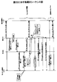
図18は、MAPのエリア内に分岐点ルータが位置する場合のハンドオーバ手順を示す図である。この場合、図2の手順5でモバイル端末1から旧アクセスルータ11へ送られる結合更新メッセージ、および手順6で旧アクセスルータ11から分岐点ルータ13へ送られる結合更新メッセージは、それぞれ、旧LCoA宛てのパケットを新LCoAへ転送するためのメッセージである。また、図2の手順13でモバイル端末1から送信される結合更新メッセージは、RCoA宛てのパケットを新LCoAへ転送するためのメッセージであって、MAPへ送られる。なお、このケースでは、分岐点ルータをMAPにするショートカットを行えば、上記手順13を省略しても、ルート最適化が犠牲になることはない。
【0114】
一方、図6の手順9でモバイル端末1から旧アクセスルータ11へ送られる結合更新メッセージは、旧LCoA宛てのパケットを新LCoAへ転送するためのメッセージである。また、図6の手順10でモバイル端末1から送信される結合更新メッセージは、RCoA宛てのパケットを新LCoAへ転送するためのメッセージであって、MAPへ送られる。
【0115】
図19は、MAPが分岐点ルータになる場合のハンドオーバ手順を示す図である。この場合、図2の手順5でモバイル端末1から旧アクセスルータ11へ送られる結合更新メッセージは、旧LCoA宛てのパケットを新LCoAへ転送するためのメッセージである。また、手順6で旧アクセスルータ11から分岐点ルータ13へ送られる結合更新メッセージは、RCoA宛てのパケットを新LCoAへ転送するためのメッセージである。なお、上記手順6においてMAPに結合更新メッセージが送られるので、図2に示す手順13、14を省略することができる。
【0116】
一方、図6の手順9でモバイル端末1から旧アクセスルータ11へ送られる結合更新メッセージは、旧LCoA宛てのパケットを新LCoAへ転送するためのメッセージである。また、図6の手順10でモバイル端末1から送信される結合更新メッセージは、RCoA宛てのパケットを新LCoAへ転送するためのメッセージであって、MAPへ送られる。
【0117】
図20は、分岐点ルータが当該MAPのエリアの外に位置する場合のハンドオーバ手順を示す図である。この場合、図2の手順5でモバイル端末1から旧アクセスルータ11へ送られる結合更新メッセージは、旧LCoA宛てのパケットを新LCoAへ転送するためのメッセージである。また、手順6で旧アクセスルータ11から分岐点ルータ13へ送られる結合更新メッセージは、旧RCoA宛てのパケットを新LCoAへ転送するためのメッセージである。さらに、図2の手順13でモバイル端末1から送信される結合更新メッセージは、新RCoA宛てのパケットを新LCoAへ転送するためのメッセージであって、MAPへ送られる。
【0118】
一方、図6の手順9でモバイル端末1から旧アクセスルータ11へ送られる結合更新メッセージは、旧LCoA宛てのパケットを新LCoAへ転送するためのメッセージである。また、図6の手順10でモバイル端末1から相手端末4やホームエージェントへ送信される結合更新メッセージは、ホームアドレス宛てのパケットを新RCoAへ転送するためのメッセージであって、ただし、上記手順10の前に、HMIPの通常の動作により、新RCoA宛てのパケットを新LCoAへ転送するための結合更新メッセージが、新MAPへ送られる。
【0119】
このように、実施形態のハンドオーバ手順は、階層化モバイルIP網においても適用可能である。すなわち、本発明は、MobileIP、MobileIPv6、階層化MobileIPv6に適用可能である。この場合、ルータ装置は、MobileIPの外部エージェント(FA:ForeignAgent)またはゲートウェイ外部エージェント(GFA:Gateway Foreign Agent)、階層化MobileIPv6のMAPであってもよい。
【0120】
また、上述の実施例では、結合更新メッセージを利用してパケットのバッファリングを制御しているが、このメッセージの代わりにICMP(Internet Control Message Protocol)メッセージを利用してもよい。なお、ICMPメッセージは、図21に示すフォーマットを有している。
【0121】
(付記1)第1のルータ装置の通信エリアにおいて第1のアドレスが割り当てられているモバイル端末がその第1のルータ装置の通信エリアから第2のルータ装置の通信エリアへ移動する際のハンドオーバ方法であって、
上記モバイル端末が上記第1のルータ装置を介して相手端末と通信を行っているときに、上記第2のルータ装置の通信エリアにおいて使用すべき第2のアドレスが上記モバイル端末に割り当てられ、
上記第1のアドレス宛てのパケットを上記第2のアドレスへ転送させるためのメッセージが、上記相手端末から上記第1のルータ装置へのルートと上記相手端末から上記第2のルータ装置へのルートとが分岐するノードに位置する分岐点ルータ装置に送られる
を特徴とするハンドオーバ方法。
【0122】
(付記2)第1のルータ装置の通信エリアにおいて第1のアドレスが割り当てられているモバイル端末がその第1のルータ装置の通信エリアから第2のルータ装置の通信エリアへ移動する際のハンドオーバ方法であって、
上記モバイル端末が上記第1のルータ装置を介して相手端末と通信を行っているときに、上記第2のルータ装置の通信エリアにおいて使用すべき第2のアドレスが上記モバイル端末に割り当てられ、
上記第2のアドレスが、上記相手端末から上記第1のルータ装置へのルートと上記相手端末から上記第2のルータ装置へのルートとが分岐するノードに位置する分岐点ルータ装置に通知され、
上記分岐点ルータ装置が、上記第1のアドレス宛てのパケットを上記第2のアドレスへ転送する
を特徴とするハンドオーバ方法。
【0123】
(付記3)付記1に記載の方法であって、
上記第1および第2のルータ装置は、ゲートウェイの配下に設けられており、上記第1のルータ装置と上記ゲートウェイとの間に設けられているルータ装置と、上記第2のルータ装置と上記ゲートウェイとの間に設けられているルータ装置とを比較し、
上記比較において互いに一致するルータ装置を上記分岐点ルータ装置として指定する。
【0124】
(付記4)付記3に記載の方法であって、
上記第1のルータ装置は、その第1のルータ装置と上記ゲートウェイとの間に設けられているルータ装置のアドレスを取得し、
上記第2のルータ装置は、その第2のルータ装置と上記ゲートウェイとの間に設けられているルータ装置のアドレスを取得し、
上記第1のルータ装置は、上記第2のルータ装置からその第2のルータ装置と上記ゲートウェイとの間に設けられているルータ装置のアドレスを取得し、上記第1のルータ装置と上記ゲートウェイとの間に設けられているルータ装置のアドレスと比較する。
【0125】
(付記5)付記1に記載の方法であって、
上記相手端末のアドレスに基づいて決まる1または複数のルータ装置に対してホップバイホップで上記メッセージが送信される。
【0126】
(付記6)付記5に記載の方法であって、
上記相手端末から上記モバイル端末へのパケットの送信元IPアドレスに基づいて、上記メッセージを送信すべき近隣ルータが決定される。
【0127】
(付記7)付記5に記載の方法であって、
上記相手端末から上記モバイル端末へのパケットの送信元MACアドレスまたは着信先MACアドレスに基づいて、上記メッセージを送信すべき近隣ルータのIPアドレスが決定される。
【0128】
(付記8)付記1に記載の方法であって、
上記分岐点ルータ装置は、階層化MobileIPのゲートウェイ外部エージェントまたは階層化MobileIPv6のモビリティアンカーポイントである。
【0129】
(付記9)第1のルータ装置の通信エリアにおいて第1のアドレスが割り当てられているモバイル端末がその第1のルータ装置の通信エリアから第2のルータ装置の通信エリアへ移動する際のハンドオーバ方法であって、
上記モバイル端末が上記第1のルータ装置を介して相手端末と通信を行っているときに、上記第2のルータ装置の通信エリアにおいて使用すべき第2のアドレスが上記モバイル端末に割り当てられ、
上記モバイル端末に上記第2のアドレスが割り当てられたときから、上記第1のアドレス宛てのパケットを上記第2のアドレスへ転送させるためのメッセージが上記第1のルータ装置に与えられるまでの期間、上記第1のルータ装置において上記第1のアドレス宛てのパケットが蓄積され、
上記メッセージが上記第2のルータ装置を介して上記第1のルータ装置に与えられたときは、上記第1のルータ装置に蓄積されたパケットが上記第2のアドレスへ転送される
を特徴とするハンドオーバ方法。
【0130】
(付記10)第1のルータ装置の通信エリアにおいて第1のアドレスが割り当てられているモバイル端末がその第1のルータ装置の通信エリアから第2のルータ装置の通信エリアへ移動する際のハンドオーバ方法であって、
上記第2のルータ装置において、その第2のルータ装置と上記モバイル端末とが接続されるまでの間、そのモバイル端末宛てのパケットを蓄積し、
上記相手端末における送信順序に従って上記蓄積されているパケットを読み出して上記モバイル端末へ送信する
を特徴とするハンドオーバ方法。
【0131】
(付記11)付記10に記載の方法であって、
上記第2のルータ装置は、TCPヘッダまたはRTPヘッダのシーケンス番号を利用してパケットの順序を制御する。
【0132】
(付記12)付記10に記載の方法であって、
上記第1のルータ装置から送られてきたパケットを第1のバッファメモリに蓄積するとともに、他のパケットを第2のバッファメモリに蓄積し、
上記第2のルータ装置と上記モバイル端末とが接続されると、上記第1のバッファメモリに蓄積されているパケットを上記モバイル端末へ送信し、その後、上記第2のバッファメモリに蓄積されているパケットを上記モバイル端末へ送信する。
【0133】
(付記13)付記1または9に記載の方法であって、
上記メッセージは、結合更新メッセージまたはICMPメッセージである。
(付記14)付記1または9に記載の方法であって、
上記第1および第2のルータ装置の少なくとも一方が、階層化MobileIPv6のモビリティアンカーポイント、またはMobileIPの外部エージェントである。
【0134】
(付記15)付記1または9に記載の方法であって、
上記モバイル端末は、MobileIP、MobileIPv6、または階層化MobileIPv6において定義されているモバイルノードである。
【0135】
(付記16)複数のルータ装置を含む移動通信システムにおいて上記複数のルータ装置の中の第1のルータ装置として使用されるルータ装置であって、
第1のルータ装置の通信エリアにおいて第1のアドレスが割り当てられているモバイル端末が第1のルータ装置の通信エリアから第2のルータ装置の通信エリアへ移動することを予測する予測手段と、
上記予測に起因して上記モバイル端末に対して上記第2のルータ装置の通信エリアにおいて使用すべき第2のアドレスが上記モバイル端末に割り当てられたときに、上記第1のアドレス宛てのパケットを上記第2のアドレスへ転送させるためのメッセージを、上記モバイル端末が通信を行っている相手端末から上記第1のルータ装置へのルートとその相手端末から上記第2のルータ装置へのルートとが分岐するノードに位置する分岐点ルータ装置に送信する指示手段と、
を有するルータ装置。
【0136】
【発明の効果】
本発明によれば、移動通信システムにおいて、ハンドオーバ時に効率の悪いパケット転送が回避される。また、ハンドオーバ時のパケットロスおよびパケットの順序逆転が回避される。
【図面の簡単な説明】
【図1】本発明の概要を説明する図である。
【図2】本発明の実施形態のハンドオーバ手順(正常動作時)を説明する図である。
【図3】図2に示す動作に対応するシーケンス図である。
【図4】分岐点ルータについて説明する図である。
【図5】ハンドオーバ起動(Handover Initiate)メッセージのフォーマットを示す図である。
【図6】本発明の実施形態のハンドオーバ手順(非正常動作時)を説明する図である。
【図7】図6に示す動作に対応するシーケンス図である。
【図8】パケットロスを回避するための手順の一例を説明するための図である。
【図9】分岐点ルータのアドレスを動的に取得する方法を模式的に示す図である。
【図10】分岐点ルータのアドレスを動的に取得する方法のフローチャートである。
【図11】ハンドオーバ応答(Handover ACK)メッセージのフォーマットを示す図である。
【図12】結合更新メッセージのフォーマットを示す図である。
【図13】MACアドレスを利用して分岐点ルータへ結合更新メッセージを送信する方法のフローチャートである。
【図14】CNアドレスを利用して分岐点ルータへ結合更新メッセージを送信する方法のフローチャートである。
【図15】旧アクセスルータにおけるバッファリング処理のフローチャートである。
【図16】モバイル端末宛てのパケットが到着したときの新アクセスルータの動作を示す図である。
【図17】モバイル端末から結合更新メッセージを受信したときの新アクセスルータの動作を示す図である。
【図18】MAPのエリア内に分岐点ルータが位置する場合のハンドオーバ手順を示す図である。
【図19】MAPが分岐点ルータになる場合のハンドオーバ手順を示す図である。
【図20】分岐点ルータがMAPのエリア外に位置する場合のハンドオーバ手順を示す図である。
【図21】ICMPメッセージのフォーマットを示す図である。
【図22】高速ハンドオーバの基本手順を説明する図である。
【図23】図22に示す処理のシーケンス図である。
【図24】非効率ルーティングについて説明する図である。
【図25】パケットの順序逆転について説明する図である。
【図26】パケットロスについて説明する図である。
【図27】パケットロスが発生する場合のシーケンス図である。
【符号の説明】
1 モバイル端末(MN)
4 相手端末(CN)
11 旧アクセスルータ
12 新アクセスルータ
13 分岐点ルータ
20 ゲートウェイ
21〜26 ルータ装置[0001]
TECHNICAL FIELD OF THE INVENTION
The present invention relates to a handover method in a mobile communication system and a router device used in the mobile communication system, and more particularly to a handover method in an IP network providing a mobile communication service and a router device therefor.
[0002]
[Prior art]
In recent years, due to the explosive spread of the Internet and mobile phones, access systems for connecting mobile users to the Internet have been diversified. As an example, currently, second generation mobile communication networks such as GPRS (General Packet Radio System) and PDC-P (Personal Digital Cellular-mobile Packet communication system), UMTS (Universal telecommunications system, etc.) , Wireless LANs, and small-scale wireless access networks such as Bluetooth have been put to practical use. In the future, fourth generation mobile communication networks and other new and new access technologies are expected. With these technologies, one terminal can be connected to a plurality of access systems, and a ubiquitous environment has come into view.
[0003]
However, it is desirable for the user to be able to connect to the Internet without being aware of the access system. Here, in order to realize such an environment, a technology for enabling a terminal to independently select or switch an access system is required. As a core technology for this purpose, MobileIP attracts attention.
[0004]
Note that MobileIP is standardized by IETF (Internet Engineering Task Force). Here, MobileIP standardized in IETF RFC2002 is based on IPv4 (RFC791). However, in recent years, the number of terminals on an IP network has been increasing, and the number of IPv4 addresses has become insufficient, and the transition from IPv4 to IPv6 (RFC2460) is being promoted. MobileIPv6 based on IPv6 has been released as an Internet draft (http://www.ietf.org/internet-drafts/draft-ietf-mobileip-ipv6-14.txt) and will be standardized soon. That is scheduled. The operation of MobileIPv6 is basically the same as MobileIP. Therefore, MobileIPv6 will be described below.
[0005]
In MobileIPv6, a home address and a care-of address (CoA: Care of Address) are generally assigned to each mobile terminal. Here, the home address is an IP address fixedly assigned to each mobile terminal. The care-of address is an IP address assigned to a mobile terminal for each access router accommodating the mobile terminal. When the mobile terminal moves, a care-of address is dynamically assigned to the mobile terminal according to the movement, so that the communication session is maintained.
[0006]
However, Mobile IPv6 handover generally has a large delay. Here, the reason why the delay becomes large is that when the mobile terminal moves from the communication area of one access router (old access router) to the communication area of another access router (new access router), the mobile terminal This is due to the mobile terminal acquiring a new care-of address by exchanging messages between them after moving to the communication area via a wireless link. Usually, the wireless performance at this time is a bottleneck of the handover time. Therefore, it is considered that MobileIPv6 is not suitable for real-time applications on UDP (RFC768) / RTP (RFC1889) such as Internet telephone and live streaming, or delay-sensitive applications on TCP (RFC793).
[0007]
As a technique for solving the above problem, a fast handover procedure has been proposed. Here, the high-speed handover procedure is disclosed as an Internet draft by the IETF (http://www.ietf.org/internet-drafts/draft-ietf-mobileip-fast-mipv6-04.txt). In the high-speed handover procedure, immediately before the mobile terminal moves from the communication area of the old access router to the communication area of the new access router, the mobile terminal acquires a new care-of address used in the communication area of the new access router. Thus, the time during which communication cannot be performed at the time of handover is reduced.
[0008]
Next, the procedure of the high-speed handover will be described. Note that the high-speed handover procedure can be classified into a method in which a network is activated and a method in which a mobile terminal is activated. The high-speed handover procedure includes a method in which a network creates an address (Stateful Address Autoconfiguration: http://www.ietf.org/internet-drafts/draft-ietf-dhc-dhcpv6-20.txt and a mobile terminal). The method can be classified into a method for creating an address (Stateless Address Autoconfiguration: RFC2462). At present, the following three types of procedures are defined.
(1) Network startup, Stateful
(2) Network startup, Stateless
(3) Mobile terminal activation, Stateless
Since the basic operations of these three methods are the same, an outline of the method (1) will be described below.
[0009]
FIG. 22 is a diagram illustrating a basic procedure of high-speed handover (Fast Handover). FIG. 23 is a sequence diagram of the processing shown in FIG. Here, a case is shown in which a mobile terminal (MN: MobileNode) 1 moves from the communication area of the old access router (AR) 2 to the communication area of the new access router (AR) 3. Further, it is assumed that the
[0010]
(1) The
[0011]
(2) When the
[0012]
(3) The
(4) The
[0013]
(5) The
[0014]
(6) Upon receiving the binding update message, the
[0015]
(7) When receiving the packet addressed to the old care-of address sent from the
(8) The
[0016]
(9) The
[0017]
(10) The
(11) The
[0018]
(12) The
[0019]
(13) Upon receiving the binding update message, the
As described above, in the high-speed handover procedure, the
[0020]
[Problems to be solved by the invention]
However, the existing high-speed handover procedure has the following three problems.
(1) Inefficient routing
(2) Reverse the order of packets
(3) Packet loss
FIG. 24 is a diagram illustrating inefficient routing. In the existing high-speed handover procedure, as described with reference to FIG. 22, when the
[0021]
FIG. 25 is a diagram for explaining packet order inversion. Here, it is assumed that packet A, packet B, and packet C are transmitted in order from the
[0022]
In this case, the packets A and B are once sent to the
[0023]
When a predetermined number (usually 3) or more of packets are reversed, retransmission processing is performed by TCP (RFC 2001) on the transmitting side, and the transmission speed is reduced. That is, in an environment using TCP, the throughput is reduced due to the packet inversion. Also, in the case of an application on UDP / RTP, when the order of the packets is reversed, the packets may be discarded. That is, in this case, conversation or instantaneous interruption of a moving image occurs.
[0024]
FIG. 26 is a diagram illustrating packet loss. FIG. 27 is a sequence diagram when a packet loss occurs. 26 and 27,
[0025]
(6) The
[0026]
(7) The
[0027]
(8) The
(9) The
[0028]
(10) The
[0029]
(11) The
(12) When receiving the packet addressed to the old care-of address, the
[0030]
(13) The
Note that when the above-described packet loss occurs, the TCP generally executes a slow start operation, and thus the throughput is reduced. In the case of a real-time application, a conversation or a momentary interruption of a moving image may occur.
[0031]
As described above, in the existing high-speed handover procedure, inefficient routing, packet order inversion, packet loss, and the like may occur.
An object of the present invention is to solve a problem of an existing handover procedure in a mobile communication system. That is, an object of the present invention is to prevent inefficient packet transfer from occurring during handover. Another object of the present invention is to prevent packet loss or packet order inversion during handover.
[0032]
[Means for Solving the Problems]
According to the handover method of the present invention, when a mobile terminal to which a first address is assigned in a communication area of a first router device moves from a communication area of the first router device to a communication area of a second router device. When the mobile terminal is communicating with the partner terminal via the first router device, a second address to be used in a communication area of the second router device is assigned to the mobile terminal. A message for transferring a packet addressed to the first address to the second address includes a route from the partner terminal to the first router device and a route from the partner terminal to the second router device. Are sent to the branch point router device located at the branching node.
[0033]
According to the above method, the message is given to the branch point router device at the time of handover of the mobile terminal. Therefore, the packet sent from the partner terminal to the first address is guided to the second router device by the branch point router device without being transferred to the first router device. That is, even at the time of handover, a packet addressed to a mobile terminal is transferred via an efficient route.
[0034]
In the above method, assuming that the first and second router devices are provided under a gateway, a router device provided between the first router device and the gateway, A router device provided between the second router device and the gateway may be compared, and router devices that match each other in the comparison may be designated as the branch point router device.
[0035]
In a handover method according to another aspect of the present invention, a mobile terminal to which a first address is assigned in a communication area of a first router device is moved from a communication area of the first router device to a communication area of a second router device. A second address to be used in the communication area of the second router device when the mobile terminal is communicating with the other terminal via the first router device when moving to the mobile terminal; And a message for causing a packet addressed to the first address to be transferred to the second address from the time when the second address is assigned to the mobile terminal is provided to the first router device. During this period, packets addressed to the first address are stored in the first router device, and the message is transmitted to the second router. Packets stored in said first router device when given to the first router device via the data device is transferred to the second address.
[0036]
In the above method, at the time of handover of a mobile terminal, a packet addressed to the mobile terminal is temporarily stored in the first router device. On the other hand, when the mobile terminal moves from the communication area of the first router device to the communication area of the second router device, the message is normally sent directly from the mobile terminal to the first router device. . However, when the communication environment between the first router device and the mobile terminal is bad, the message cannot be sent directly from the mobile terminal to the first router device, and the second router device cannot transmit the message. After moving to the communication area, the message is sent to the first router device via the second router device. Therefore, when the first router device receives the message via the second router device, the first router device considers that the packet to be received by the mobile terminal at the time of handover is not received by the mobile terminal, and stores the packet. Retransmit the packet to the mobile terminal. As a result, packet loss is avoided.
[0037]
In the second router device, packets destined for the mobile terminal are stored until the second router device is connected to the mobile terminal, and the packets are stored in accordance with the transmission order at the partner terminal. The mobile station may read out the packet and send it to the mobile terminal. According to this method, even if the order of the packets addressed to the mobile terminal is changed during the handover, the order is correctly rearranged in the second router device.
[0038]
BEST MODE FOR CARRYING OUT THE INVENTION
Hereinafter, embodiments of the present invention will be described with reference to the drawings.
FIG. 1 is a diagram for explaining the outline of the present invention. In FIG. 1, a mobile terminal (MN: Mobile Node) 1 is communicating with a correspondent terminal (CN: Correspondent Node) 4. The old care-of address is assigned to the
(1) Inefficient routing
In the handover procedure of the present invention, when the
[0039]
After receiving the binding update message, when receiving a packet addressed to the old care-of address assigned to the
(2) Packet order reversal
The
[0040]
The order of the packets can be appropriately rearranged by using an existing buffer management algorithm. Specifically, for example, sequence management can be realized by using a sequence number set in a TCP header or an RTP header of each packet.
(3) Packet loss
The
[0041]
Thereafter, the
[0042]
As described above, in the procedure of the present invention, if the
[0043]
Next, embodiments of the present invention will be described in detail.
FIG. 2 is a diagram illustrating a handover procedure (during normal operation) according to the embodiment of this invention. FIG. 3 is a sequence diagram corresponding to the operation shown in FIG.
[0044]
The
[0045]
The carrier network includes a plurality of router devices. Here, each router device has a function of routing a packet according to its destination address. On the other hand, the
[0046]
In the mobile communication network, when the
[0047]
The
[0048]
In the mobile communication network, it is assumed that the
[0049]
The handover procedure in this case is as follows. In the following description, it is assumed that stateful address autoconfiguration is used.
(1) The
[0050]
(2) When the
[0051]
The format of the handover activation message is known, and includes a type area, a code area, a checksum area, an identifier area, S bits, U bits, H bits, T bits, R bits, and an option area. However, in the system of the present embodiment, the I bit and the D bit are newly defined. Here, the I bit is used to request that the stored packets be rearranged correctly according to the buffer management algorithm. The D bit is used when requesting the IP address of a router device located between the new access router and the domain gateway.
[0052]
In
[0053]
(3) The
[0054]
(4) The
[0055]
(5) The
[0056]
(6) Upon receiving the binding update message, the
[0057]
In this case, the
[0058]
Further, the
[0059]
(7) The
[0060]
(8) The
[0061]
(9) Upon receiving a packet addressed to the new care-of address, the
[0062]
(10) When entering the communication area of the
[0063]
(11) The
[0064]
(12) The
(13) The
[0065]
(14) Upon receiving the binding update message, the
As described above, in the procedure of the embodiment, the problem of the inefficient routing described with reference to FIG. 24 is solved by transmitting the binding update message to the
[0066]
FIG. 6 is a diagram illustrating a handover procedure (during abnormal operation) according to the embodiment of this invention. FIG. 7 is a sequence diagram corresponding to the operation shown in FIG. Here, it is assumed that in
[0067]
In
[0068]
(6) The
(7) When entering the communication area of the
[0069]
(8) The
[0070]
(9) The
[0071]
(10) The
[0072]
(11) Upon receiving the binding update message sent from the
[0073]
In this case, the
[0074]
(12) Upon receiving the binding update message in step 10, the
As described above, in the handover method according to the embodiment, when the
[0075]
An example is shown. Here, as shown in FIG. 8, it is assumed that
[0076]
Thereafter, it is assumed that the
[0077]
Next, a method in which the
(1) When the address of the branch point router is defined in advance
(2) When dynamically acquiring the address of a branch point router
(3) When the address of the branch point router cannot be obtained (using MAC address)
(4) When the address of the branch point router cannot be obtained (using CN address)
(1) When the address of the branch point router is defined in advance
In this case, the destination of the
[0078]
(2) When dynamically acquiring the address of a branch point router
In this case, it is assumed that each router device knows the address of the
[0079]
FIG. 9 is a diagram schematically illustrating a method of dynamically acquiring the address of a branch point router. Here, it is assumed that the IP addresses assigned to the
[0080]
In the above network, when the
[0081]
FIG. 10 is a flowchart of a method for dynamically acquiring the address of a branch point router. Note that the process of this flowchart is executed by the
[0082]
In step S1, the occurrence of a handover is predicted based on the position of the
[0083]
In step S2, it is checked whether the IP address of the branch point router corresponding to the combination of the
[0084]
In step S4, a request is made to the
[0085]
FIG. 11 is a diagram showing a format of a handover response (Handover ACK) message. This message is used to notify the address. Specifically, when "1" is set as the sub-type (Sub-Type), the old care-of address is written in the address area, and when "2" is set, the new care-of address is written in the address area. The address is written. In the embodiment, “3” is newly defined as a subtype. When notifying one or more addresses registered in the router management list from the
[0086]
In step S5, a router management list in which the addresses of router devices provided between the
[0087]
In step S6, the address of the router provided between the
[0088]
(3) When the address of the branch point router cannot be obtained (using MAC address)
In this case, the
[0089]
The binding update message used in this embodiment has a newly defined R bit as shown in FIG. Here, the R bit is a bit for requesting “repeat”, and the router device that has received the binding update message in which the R bit is set transfers the message to the corresponding next hop router.
[0090]
The binding update message is sent to the gateway by repeating the above processing in each router device. That is, the binding cache of each router provided between the
[0091]
In the above example, the source MAC address of the packet addressed to the
FIG. 13 is a flowchart of a method for transmitting a binding update message to a branch point router using a MAC address. Steps S1 to S3 are the same as the method shown in FIG.
[0092]
In steps S11 and S12, when the binding update message is received from the
[0093]
On the other hand, when a packet addressed to the
[0094]
Upon receiving the binding update message, the neighboring router first updates the binding cache according to the message in step S21. Subsequently, since "1" is set in the R bit, steps S12 to S17 are executed. Note that these processes are the same as those performed in the
[0095]
(4) When the address of the branch point router cannot be obtained (using CN address)
FIG. 14 is a flowchart of a method for transmitting a binding update message to a branch point router using a CN address. The method of using the CN address (IP address of the partner terminal 4) is basically the same as the method of using the MAC address described above. However, in the method using the CN address, when a packet destined for the
[0096]
Next, a process of storing / forwarding a packet addressed to the old care-of address in the
[0097]
FIG. 15 is a flowchart of the buffering process in the
[0098]
In step S41, the received new care-of address or prefix is transmitted to the
[0099]
In steps S44 and S45, the
[0100]
If the source address of the binding update message is the old care-of address, it is considered that the message of
[0101]
On the other hand, if the source address of the binding update message is the new care-of address, it is considered that the message of
[0102]
Further, when the binding update message cannot be received from the
[0103]
If the
[0104]
Next, a method of controlling the order of packets in the
FIG. 16 is a diagram illustrating an operation of the
[0105]
In step S51, first, a neighbor cache (Neighbour Cache) is accessed using the destination address of the received packet (the new care-of address of the mobile terminal 1) as a key to check the registered state. If “REACHABLE” has been registered, the received packet is transferred to the
[0106]
If the source address of the received packet is the
[0107]
FIG. 17 is a diagram showing the operation of the
[0108]
In step S61, the state of the
[0109]
As described above, when both the packet transferred from the
[0110]
Next, a case where the handover method of the embodiment is applied to a hierarchical network using HMIPv6 (Hierarchical Mobile Ipv6) will be described. Note that HMIPv6 itself is available at http: // www. ief. org / internet-drafts / draft-ietf-mobileip-hmipv6-04. txt.
[0111]
HMIP (including HMIPv6) hierarchically manages the location or movement of a mobile terminal using a mobility anchor point (MAP). Here, the MAP is provided in the external domain and manages the movement of the mobile terminal within the area managed by the MAP. In the HMIPv6 Basic Mode, each mobile terminal is provided with an address RCoA (Regional Care-of-Address) fixedly determined in the MAP area and an address LCoA (Local Care-of-Address) changed for each access router in the MAP area. ) Is assigned. Therefore, when the mobile terminal moves between MAPs, a process of registering the MAP and a process of transmitting a binding update message to the home agent are required. The location registration is completed only by sending the binding update message to Incidentally, in general MobileIPv6, a binding update message is sent to the home agent every time the mobile terminal moves.
[0112]
The handover procedure in HMIPv6 is basically the same as in MobileIPv6. However, the content of the binding update message and its destination differ.
[0113]
FIG. 18 is a diagram illustrating a handover procedure when a branch point router is located in the MAP area. In this case, the binding update message sent from the
[0114]
On the other hand, the binding update message sent from the
[0115]
FIG. 19 is a diagram illustrating a handover procedure when the MAP becomes a branch point router. In this case, the binding update message sent from the
[0116]
On the other hand, the binding update message sent from the
[0117]
FIG. 20 is a diagram illustrating a handover procedure when the branch point router is located outside the area of the MAP. In this case, the binding update message sent from the
[0118]
On the other hand, the binding update message sent from the
[0119]
As described above, the handover procedure according to the embodiment is also applicable to a hierarchical mobile IP network. That is, the present invention is applicable to MobileIP, MobileIPv6, and hierarchical MobileIPv6. In this case, the router device may be an external agent of MobileIP (FA: ForeignAgent) or a gateway external agent (GFA: Gateway Foreign Agent), or a MAP of hierarchical MobileIPv6.
[0120]
Further, in the above-described embodiment, packet buffering is controlled using the binding update message. However, an ICMP (Internet Control Message Protocol) message may be used instead of this message. The ICMP message has a format shown in FIG.
[0121]
(Supplementary Note 1) A handover method when a mobile terminal to which a first address is assigned in a communication area of a first router device moves from a communication area of the first router device to a communication area of a second router device. And
When the mobile terminal is communicating with the partner terminal via the first router device, a second address to be used in a communication area of the second router device is assigned to the mobile terminal,
A message for transferring a packet addressed to the first address to the second address includes a route from the partner terminal to the first router device and a route from the partner terminal to the second router device. Is sent to the branch point router device located at the branching node
The handover method characterized by the above-mentioned.
[0122]
(Supplementary Note 2) A handover method when a mobile terminal to which a first address is assigned in a communication area of a first router device moves from a communication area of the first router device to a communication area of a second router device. And
When the mobile terminal is communicating with the partner terminal via the first router device, a second address to be used in a communication area of the second router device is assigned to the mobile terminal,
The second address is notified to a branch point router device located at a node where a route from the partner terminal to the first router device and a route from the partner terminal to the second router device branch;
The branch point router device transfers a packet addressed to the first address to the second address.
The handover method characterized by the above-mentioned.
[0123]
(Supplementary note 3) The method according to
The first and second router devices are provided under a gateway, and a router device provided between the first router device and the gateway; a second router device and the gateway; And the router device provided between the
Router devices that match each other in the comparison are designated as the branch point router devices.
[0124]
(Supplementary note 4) The method according to
The first router device obtains an address of a router device provided between the first router device and the gateway,
The second router device obtains an address of a router device provided between the second router device and the gateway,
The first router device obtains an address of a router device provided between the second router device and the gateway from the second router device, and obtains an address of the first router device and the gateway from the second router device. Is compared with the address of the router device provided between them.
[0125]
(Supplementary Note 5) The method according to
The message is transmitted hop-by-hop to one or a plurality of router devices determined based on the address of the partner terminal.
[0126]
(Supplementary note 6) The method according to
A neighboring router to which the message is to be transmitted is determined based on a source IP address of a packet from the partner terminal to the mobile terminal.
[0127]
(Supplementary note 7) The method according to
An IP address of a neighboring router to which the message should be transmitted is determined based on a source MAC address or a destination MAC address of a packet from the partner terminal to the mobile terminal.
[0128]
(Supplementary Note 8) The method according to
The branch point router device is a layered MobileIP gateway foreign agent or a layered MobileIPv6 mobility anchor point.
[0129]
(Supplementary Note 9) A handover method when a mobile terminal to which a first address is assigned in the communication area of the first router device moves from the communication area of the first router device to the communication area of the second router device. And
When the mobile terminal is communicating with the partner terminal via the first router device, a second address to be used in a communication area of the second router device is assigned to the mobile terminal,
A period from when the second address is assigned to the mobile terminal to when a message for causing a packet addressed to the first address to be transferred to the second address is given to the first router device; Packets addressed to the first address are stored in the first router device,
When the message is given to the first router device via the second router device, the packet stored in the first router device is transferred to the second address.
The handover method characterized by the above-mentioned.
[0130]
(Supplementary Note 10) A handover method when a mobile terminal to which a first address is assigned in a communication area of a first router device moves from a communication area of the first router device to a communication area of a second router device. And
In the second router device, a packet addressed to the mobile terminal is accumulated until the second router device is connected to the mobile terminal,
The stored packets are read out according to the transmission order in the partner terminal and transmitted to the mobile terminal.
The handover method characterized by the above-mentioned.
[0131]
(Supplementary note 11) The method according to supplementary note 10, wherein
The second router device controls the order of packets using the sequence number of the TCP header or the RTP header.
[0132]
(Supplementary Note 12) The method according to supplementary note 10, wherein
The packet sent from the first router device is stored in a first buffer memory, and the other packets are stored in a second buffer memory.
When the second router device is connected to the mobile terminal, the packet stored in the first buffer memory is transmitted to the mobile terminal, and then the packet is stored in the second buffer memory. Transmit the packet to the mobile terminal.
[0133]
(Supplementary Note 13) The method according to
The message is a binding update message or an ICMP message.
(Supplementary Note 14) The method according to
At least one of the first and second router devices is a mobility anchor point of Hierarchical MobileIPv6 or a foreign agent of MobileIP.
[0134]
(Supplementary Note 15) The method according to
The mobile terminal is a mobile node defined in MobileIP, MobileIPv6, or Hierarchical MobileIPv6.
[0135]
(Supplementary Note 16) A router device used as a first router device among the plurality of router devices in a mobile communication system including a plurality of router devices,
Prediction means for predicting that a mobile terminal to which a first address is assigned in the communication area of the first router device moves from the communication area of the first router device to the communication area of the second router device;
When a second address to be used in the communication area of the second router device is assigned to the mobile terminal due to the prediction, the packet addressed to the first address is transmitted to the mobile terminal. A message for transferring to the second address is divided into a route from the partner terminal with which the mobile terminal is communicating to the first router device and a route from the partner terminal to the second router device. Instruction means for transmitting to a branch point router device located at a node to
Router device having
[0136]
【The invention's effect】
According to the present invention, in a mobile communication system, inefficient packet transfer at the time of handover is avoided. In addition, packet loss and inversion of packet order during handover are avoided.
[Brief description of the drawings]
FIG. 1 is a diagram illustrating an outline of the present invention.
FIG. 2 is a diagram illustrating a handover procedure (during normal operation) according to the embodiment of this invention.
FIG. 3 is a sequence diagram corresponding to the operation shown in FIG. 2;
FIG. 4 is a diagram illustrating a branch point router.
FIG. 5 is a diagram showing a format of a handover start (Handover Initiate) message.
FIG. 6 is a diagram illustrating a handover procedure (during abnormal operation) according to the embodiment of this invention.
FIG. 7 is a sequence diagram corresponding to the operation shown in FIG. 6;
FIG. 8 is a diagram illustrating an example of a procedure for avoiding a packet loss.
FIG. 9 is a diagram schematically illustrating a method of dynamically acquiring an address of a branch point router.
FIG. 10 is a flowchart of a method for dynamically acquiring an address of a branch point router.
FIG. 11 is a diagram showing a format of a handover response (Handover ACK) message.
FIG. 12 is a diagram showing a format of a binding update message.
FIG. 13 is a flowchart of a method for transmitting a binding update message to a branch point router using a MAC address.
FIG. 14 is a flowchart of a method for transmitting a binding update message to a branch point router using a CN address.
FIG. 15 is a flowchart of a buffering process in the old access router.
FIG. 16 is a diagram illustrating an operation of a new access router when a packet addressed to a mobile terminal arrives.
FIG. 17 is a diagram illustrating an operation of a new access router when a binding update message is received from a mobile terminal.
FIG. 18 is a diagram illustrating a handover procedure when a branch point router is located in an area of a MAP.
FIG. 19 is a diagram showing a handover procedure when the MAP becomes a branch point router.
FIG. 20 is a diagram showing a handover procedure when the branch point router is located outside the MAP area.
FIG. 21 is a diagram showing a format of an ICMP message.
FIG. 22 is a diagram illustrating a basic procedure of a high-speed handover.
FIG. 23 is a sequence diagram of the processing shown in FIG. 22;
FIG. 24 is a diagram illustrating inefficient routing.
FIG. 25 is a diagram illustrating packet order inversion.
FIG. 26 is a diagram illustrating packet loss.
FIG. 27 is a sequence diagram when a packet loss occurs.
[Explanation of symbols]
1 Mobile terminal (MN)
4 partner terminal (CN)
11 Old access router
12. New access router
13. Branch point router
20 Gateway
21-26 router device
Claims (5)
上記モバイル端末が上記第1のルータ装置を介して相手端末と通信を行っているときに、上記第2のルータ装置の通信エリアにおいて使用すべき第2のアドレスが上記モバイル端末に割り当てられ、
上記第1のアドレス宛てのパケットを上記第2のアドレスへ転送させるためのメッセージが、上記相手端末から上記第1のルータ装置へのルートと上記相手端末から上記第2のルータ装置へのルートとが分岐するノードに位置する分岐点ルータ装置に送られる
を特徴とするハンドオーバ方法。A handover method when a mobile terminal to which a first address is assigned in a communication area of a first router device moves from a communication area of the first router device to a communication area of a second router device,
When the mobile terminal is communicating with the partner terminal via the first router device, a second address to be used in a communication area of the second router device is assigned to the mobile terminal,
A message for transferring a packet addressed to the first address to the second address includes a route from the partner terminal to the first router device and a route from the partner terminal to the second router device. Is sent to a branch point router device located at a branching node.
上記第1および第2のルータ装置は、ゲートウェイの配下に設けられており、上記第1のルータ装置と上記ゲートウェイとの間に設けられているルータ装置と、上記第2のルータ装置と上記ゲートウェイとの間に設けられているルータ装置とを比較し、
上記比較において互いに一致するルータ装置を上記分岐点ルータ装置として指定する。The method of claim 1, wherein
The first and second router devices are provided under a gateway, and a router device provided between the first router device and the gateway; a second router device and the gateway; And the router device provided between the
Router devices that match each other in the comparison are designated as the branch point router devices.
上記モバイル端末が上記第1のルータ装置を介して相手端末と通信を行っているときに、上記第2のルータ装置の通信エリアにおいて使用すべき第2のアドレスが上記モバイル端末に割り当てられ、
上記モバイル端末に上記第2のアドレスが割り当てられたときから、上記第1のアドレス宛てのパケットを上記第2のアドレスへ転送させるためのメッセージが上記第1のルータ装置に与えられるまでの期間、上記第1のルータ装置において上記第1のアドレス宛てのパケットが蓄積され、
上記メッセージが上記第2のルータ装置を介して上記第1のルータ装置に与えられたときは、上記第1のルータ装置に蓄積されたパケットが上記第2のアドレスへ転送される
を特徴とするハンドオーバ方法。A handover method when a mobile terminal to which a first address is assigned in a communication area of a first router device moves from a communication area of the first router device to a communication area of a second router device,
When the mobile terminal is communicating with the partner terminal via the first router device, a second address to be used in a communication area of the second router device is assigned to the mobile terminal,
A period from when the second address is assigned to the mobile terminal to when a message for causing a packet addressed to the first address to be transferred to the second address is given to the first router device; Packets addressed to the first address are stored in the first router device,
When the message is given to the first router device via the second router device, a packet stored in the first router device is transferred to the second address. Handover method.
上記第2のルータ装置において、その第2のルータ装置と上記モバイル端末とが接続されるまでの間、そのモバイル端末宛てのパケットを蓄積し、
上記相手端末における送信順序に従って上記蓄積されているパケットを読み出して上記モバイル端末へ送信する
を特徴とするハンドオーバ方法。A handover method when a mobile terminal to which a first address is assigned in a communication area of a first router device moves from a communication area of the first router device to a communication area of a second router device,
In the second router device, a packet addressed to the mobile terminal is accumulated until the second router device is connected to the mobile terminal,
A handover method comprising: reading out the stored packets in accordance with the transmission order at the partner terminal and transmitting the packets to the mobile terminal.
第1のルータ装置の通信エリアにおいて第1のアドレスが割り当てられているモバイル端末が第1のルータ装置の通信エリアから第2のルータ装置の通信エリアへ移動することを予測する予測手段と、
上記予測に起因して上記モバイル端末に対して上記第2のルータ装置の通信エリアにおいて使用すべき第2のアドレスが上記モバイル端末に割り当てられたときに、上記第1のアドレス宛てのパケットを上記第2のアドレスへ転送させるためのメッセージを、上記モバイル端末が通信を行っている相手端末から上記第1のルータ装置へのルートとその相手端末から上記第2のルータ装置へのルートとが分岐するノードに位置する分岐点ルータ装置に送信する指示手段と、
を有するルータ装置。A router device used as a first router device among the plurality of router devices in a mobile communication system including a plurality of router devices,
Prediction means for predicting that a mobile terminal to which a first address is assigned in the communication area of the first router device moves from the communication area of the first router device to the communication area of the second router device;
When a second address to be used in the communication area of the second router device is assigned to the mobile terminal due to the prediction, the packet addressed to the first address is transmitted to the mobile terminal. A message for transferring to the second address is divided into a route from the partner terminal with which the mobile terminal is communicating to the first router device and a route from the partner terminal to the second router device. Instruction means for transmitting to a branch point router device located at a node to
Router device having
Priority Applications (3)
| Application Number | Priority Date | Filing Date | Title |
|---|---|---|---|
| JP2002162421A JP2004015143A (en) | 2002-06-04 | 2002-06-04 | Hand-over method in mobile communication system and router used for the mobile communication system |
| US10/373,538 US20030225892A1 (en) | 2002-06-04 | 2003-02-25 | Handover method in mobile communication system and router device used in mobile communication system |
| CNB031195652A CN1243436C (en) | 2002-06-04 | 2003-03-11 | Handover method in mobile communication system and router device used in mobile communication system |
Applications Claiming Priority (1)
| Application Number | Priority Date | Filing Date | Title |
|---|---|---|---|
| JP2002162421A JP2004015143A (en) | 2002-06-04 | 2002-06-04 | Hand-over method in mobile communication system and router used for the mobile communication system |
Publications (1)
| Publication Number | Publication Date |
|---|---|
| JP2004015143A true JP2004015143A (en) | 2004-01-15 |
Family
ID=29561669
Family Applications (1)
| Application Number | Title | Priority Date | Filing Date |
|---|---|---|---|
| JP2002162421A Pending JP2004015143A (en) | 2002-06-04 | 2002-06-04 | Hand-over method in mobile communication system and router used for the mobile communication system |
Country Status (3)
| Country | Link |
|---|---|
| US (1) | US20030225892A1 (en) |
| JP (1) | JP2004015143A (en) |
| CN (1) | CN1243436C (en) |
Cited By (18)
| Publication number | Priority date | Publication date | Assignee | Title |
|---|---|---|---|---|
| WO2005053249A1 (en) * | 2003-11-28 | 2005-06-09 | Matsushita Electric Industrial Co., Ltd. | Communication system and communication method |
| WO2005083950A1 (en) * | 2004-02-27 | 2005-09-09 | Mitsubishi Electric Corporation | Layer 2 switch network |
| WO2006011567A1 (en) * | 2004-07-30 | 2006-02-02 | Matsushita Electric Industrial Co., Ltd. | New path setting method, mobile terminal, and path managing device |
| JP2006041742A (en) * | 2004-07-23 | 2006-02-09 | Mitsubishi Electric Corp | Handover method, wireless base station, and wireless terminal station |
| JP2006109452A (en) * | 2004-09-30 | 2006-04-20 | Lucent Technol Inc | Active session mobility solution for point-to-point protocol |
| KR100594819B1 (en) | 2004-08-03 | 2006-07-03 | 한국전자통신연구원 | Hand-over method |
| WO2006123657A1 (en) * | 2005-05-16 | 2006-11-23 | Ntt Docomo, Inc. | Access router device, mobility control system, and mobility control method |
| WO2007119598A1 (en) * | 2006-03-31 | 2007-10-25 | Matsushita Electric Industrial Co., Ltd. | HIGH-SPEED QoS HANDOVER METHOD AND PROCESSING NODE USED IN THE METHOD |
| WO2007125592A1 (en) * | 2006-04-28 | 2007-11-08 | Panasonic Corporation | Communication apparatus and handover method |
| WO2007141879A1 (en) * | 2006-06-09 | 2007-12-13 | Panasonic Corporation | Node device |
| JP2008300992A (en) * | 2007-05-29 | 2008-12-11 | Kyocera Corp | Communication device and wireless communication method |
| JP2009503991A (en) * | 2005-07-25 | 2009-01-29 | テレフオンアクチーボラゲット エル エム エリクソン(パブル) | Means and methods for improving handover characteristics of radio access networks |
| JP2009177264A (en) * | 2008-01-22 | 2009-08-06 | Fujitsu Ltd | Network system, data transmission/reception method, and data transmission/reception program |
| WO2009119765A1 (en) * | 2008-03-27 | 2009-10-01 | 京セラ株式会社 | Wireless communication device and communication device |
| US7720059B2 (en) | 2005-03-03 | 2010-05-18 | Samsung Electronics Co., Ltd. | Traffic exchanging method for mobile node in mobile internet protocol version 6 (MIPv6) network |
| JP2011505758A (en) * | 2007-11-27 | 2011-02-24 | クゥアルコム・インコーポレイテッド | Method and apparatus for handling out-of-order packets during handover in a wireless communication system |
| JP2015534295A (en) * | 2012-08-07 | 2015-11-26 | コーニンクレッカ フィリップス エヌ ヴェKoninklijke Philips N.V. | Timed lighting control |
| CN105430703A (en) * | 2015-11-04 | 2016-03-23 | 宁波大学 | Low-consumption method for realizing FMIPv6 switching method in Android terminal |
Families Citing this family (51)
| Publication number | Priority date | Publication date | Assignee | Title |
|---|---|---|---|---|
| DE10241957A1 (en) * | 2002-09-10 | 2004-03-18 | Siemens Ag | Data communication system and system for updating of software of computers connected to the network wherein prior to transfer of upgrade data, the type of communications medium is first determined |
| DE602004011904D1 (en) * | 2003-02-27 | 2008-04-03 | Koninkl Philips Electronics Nv | METHOD AND WIRELESS COMPONENT FOR AVOIDING TCP PACKET TRANSMISSION DURING TRANSMISSION OF A MOBILE DEVICE |
| GB2399476B (en) * | 2003-03-14 | 2006-08-16 | Matsushita Electric Ind Co Ltd | Fast handover in mobile communications networks |
| GB0312681D0 (en) * | 2003-06-03 | 2003-07-09 | Ericsson Telefon Ab L M | IP mobility |
| US7917152B2 (en) * | 2003-06-27 | 2011-03-29 | Nokia Corporation | Enhanced fast handover procedures |
| US7548525B2 (en) * | 2003-10-18 | 2009-06-16 | Samsung Electronics Co., Ltd | System and method for providing handover of a mobile IP terminal in a wireless network |
| JP2005160053A (en) * | 2003-11-04 | 2005-06-16 | Matsushita Electric Ind Co Ltd | Mobile communication method, mobile communication device, home agent apparatus, access router information server apparatus, and mobile communication system |
| JP4567004B2 (en) * | 2003-11-26 | 2010-10-20 | 韓國電子通信研究院 | Mobile IPv6 fast handover method based on access router |
| US7590742B2 (en) * | 2003-12-16 | 2009-09-15 | Nokia Corporation | IP address management |
| KR100827105B1 (en) * | 2004-02-13 | 2008-05-02 | 삼성전자주식회사 | Method and apparatus for ranging to support fast handover in broadband wireless communication system |
| JP4574193B2 (en) | 2004-03-04 | 2010-11-04 | 株式会社エヌ・ティ・ティ・ドコモ | Mobile communication network system and mobility management apparatus |
| EP1578059A1 (en) * | 2004-03-19 | 2005-09-21 | Swisscom Mobile AG | WLAN handover |
| KR100594124B1 (en) * | 2004-05-07 | 2006-06-28 | 삼성전자주식회사 | High Speed Handover System and Method in Broadband Wireless Access Communication System |
| JP4423118B2 (en) * | 2004-06-08 | 2010-03-03 | 株式会社エヌ・ティ・ティ・ドコモ | Mobile communication system, access router, management apparatus, and mobile communication method |
| RU2007101156A (en) * | 2004-06-11 | 2008-07-20 | Мацусита Электрик Индастриал Ко. | METHOD FOR TRANSMISSION OF COMMUNICATION SERVICES AND METHOD FOR PROCESSING COMMUNICATION MESSAGES |
| KR20060012099A (en) * | 2004-08-02 | 2006-02-07 | 엘지전자 주식회사 | Method of executing handover in a broadband wireless access system |
| JP4766860B2 (en) * | 2004-09-07 | 2011-09-07 | 株式会社エヌ・ティ・ティ・ドコモ | Mobile communication system, handover control apparatus, and handover control method |
| CN101112055A (en) * | 2005-01-28 | 2008-01-23 | 松下电器产业株式会社 | Packet transfer control method, communication message processing method, access router, and mobile terminal |
| US7508793B2 (en) * | 2005-03-07 | 2009-03-24 | Telefonaktiebolaget L M Ericsson (Publ) | Micro mobility management |
| WO2006106846A1 (en) * | 2005-03-30 | 2006-10-12 | Matsushita Electric Industrial Co., Ltd. | Communication handover method and communication message processing method |
| US7532597B2 (en) * | 2005-06-15 | 2009-05-12 | Motorola, Inc. | Method and apparatus to facilitate handover |
| IL169503A (en) * | 2005-07-03 | 2010-12-30 | Alvarion Ltd | Method and apparatus for allowing transfer of communication sessions between base stations in wireless networks |
| KR101201043B1 (en) * | 2005-07-05 | 2012-11-14 | 삼성전자주식회사 | Fast handover method for ipv6 over ieee 802.16 network |
| KR100893213B1 (en) * | 2005-07-08 | 2009-04-16 | 삼성전자주식회사 | Apparatus and Method for Controlling Data in Mobile Network |
| KR100818916B1 (en) * | 2005-09-12 | 2008-04-03 | 삼성전자주식회사 | Mobile node and data server for providing information on an IP address allocation, and method for providing information on an IP address allocation |
| US20070091875A1 (en) * | 2005-10-22 | 2007-04-26 | Revnx, Inc. | Method and System For Device Mobility Using Application Label Switching In A Mobile Communication Network |
| KR100656358B1 (en) * | 2005-10-25 | 2006-12-11 | 한국전자통신연구원 | Method for handover in mobile ip network |
| US8059581B2 (en) * | 2006-01-05 | 2011-11-15 | Qualcomm Incorporated | Method and apparatus for seamless and efficient wireless handoffs |
| KR100656479B1 (en) * | 2006-01-09 | 2006-12-11 | 삼성전자주식회사 | Apparatus for supplying mobile ipv6 |
| US7814311B2 (en) * | 2006-03-10 | 2010-10-12 | Cisco Technology, Inc. | Role aware network security enforcement |
| US8406191B2 (en) * | 2006-04-14 | 2013-03-26 | Qualcomm Incorporated | Pseudo wires for mobility management |
| US7983219B2 (en) * | 2006-06-07 | 2011-07-19 | Qualcomm Incorporated | Handoff of an access terminal at the network layer in an access network |
| CN101047996B (en) * | 2006-06-09 | 2010-11-10 | 华为技术有限公司 | Method, system for acquiring target network transmission address information and its application |
| CN101005444B (en) * | 2006-06-24 | 2011-12-07 | 华为技术有限公司 | Method and device for quick switching |
| JP4825913B2 (en) * | 2007-03-20 | 2011-11-30 | 富士通株式会社 | Base station and method for reducing transfer delay due to handover processing |
| JP4794520B2 (en) * | 2007-05-16 | 2011-10-19 | Kddi株式会社 | System, access gateway, home agent, and program for optimizing communication path in network-driven mobility management protocol |
| US20080298592A1 (en) * | 2007-05-29 | 2008-12-04 | Mohamed Khalid | Technique for changing group member reachability information |
| EP2178335A1 (en) * | 2007-08-09 | 2010-04-21 | Fujitsu Limited | Handover method in radio communication system, radio base station, and radio terminal |
| US8085793B2 (en) * | 2007-09-24 | 2011-12-27 | Telefonaktiebolaget Lm Ericsson (Publ) | Traffic localization with proxy mobility |
| CN101127727B (en) * | 2007-09-28 | 2012-07-04 | 电信科学技术研究院 | IP address configuration and mobile detection method for mobile IP |
| MY164506A (en) * | 2008-01-28 | 2017-12-29 | Mimos Berhad | A method and system for handoff control in a wireless communication network |
| US8792490B2 (en) * | 2009-03-16 | 2014-07-29 | Cisco Technology, Inc. | Logically partitioned networking devices |
| US9143462B2 (en) * | 2009-04-10 | 2015-09-22 | International Business Machines Corporation | Large send support in layer 2 switch to enhance effectiveness of large receive on NIC and overall network throughput |
| EP2628280B1 (en) * | 2010-10-13 | 2018-05-16 | Samsung Electronics Co., Ltd | Method and apparatus for multiplexing machine type communication data of multiple mtc devices in a wireless network environment |
| CN102469449B (en) * | 2010-11-15 | 2016-03-30 | 上海贝尔股份有限公司 | Routing optimization method in an IPv6 low-consumption wireless territory net |
| KR101210613B1 (en) * | 2010-11-30 | 2012-12-11 | 주식회사 케이티 | System and method for providing mobile p2p service |
| CN102387068B (en) * | 2011-09-29 | 2014-05-07 | 中国人民解放军国防科学技术大学 | Extensible routing method and router of identification network |
| US9271193B2 (en) * | 2012-02-24 | 2016-02-23 | Intel Deutschland Gmbh | Care-of-address handover |
| US10735545B2 (en) * | 2016-06-06 | 2020-08-04 | International Business Machines Corporation | Routing vault access requests in a dispersed storage network |
| CN106658479B (en) | 2016-11-16 | 2020-12-11 | 广东新岸线科技有限公司 | Method for realizing wireless network convergence |
| CN110830573B (en) * | 2019-11-06 | 2023-06-02 | 广东电网有限责任公司广州供电局 | Local communication converter and automatic data synchronization method thereof |
Family Cites Families (6)
| Publication number | Priority date | Publication date | Assignee | Title |
|---|---|---|---|---|
| FI101763B1 (en) * | 1995-12-01 | 1998-08-14 | Nokia Mobile Phones Ltd | The retention of the transported information composition between base station switches |
| FI109503B (en) * | 1997-04-15 | 2002-08-15 | Nokia Corp | Prevention of packet loss during handover in a packet-based telecommunications network and handover procedure |
| US6804221B1 (en) * | 2000-06-26 | 2004-10-12 | Alcatel | Micromobility using multicast |
| US7158497B2 (en) * | 2000-08-31 | 2007-01-02 | Nortel Networks Limited | Methods and apparatus for supporting micro-mobility within a radio access network |
| JP4053227B2 (en) * | 2000-10-18 | 2008-02-27 | 三菱電機株式会社 | Handoff method and agent device |
| US7561553B2 (en) * | 2002-02-27 | 2009-07-14 | Motorola, Inc. | Method and apparatus for providing IP mobility for mobile networks and detachable mobile network nodes |
-
2002
- 2002-06-04 JP JP2002162421A patent/JP2004015143A/en active Pending
-
2003
- 2003-02-25 US US10/373,538 patent/US20030225892A1/en not_active Abandoned
- 2003-03-11 CN CNB031195652A patent/CN1243436C/en not_active Expired - Fee Related
Cited By (29)
| Publication number | Priority date | Publication date | Assignee | Title |
|---|---|---|---|---|
| US8051198B2 (en) | 2003-11-28 | 2011-11-01 | Panasonic Corporation | Communication system and communication method |
| WO2005053249A1 (en) * | 2003-11-28 | 2005-06-09 | Matsushita Electric Industrial Co., Ltd. | Communication system and communication method |
| WO2005083950A1 (en) * | 2004-02-27 | 2005-09-09 | Mitsubishi Electric Corporation | Layer 2 switch network |
| JP2006041742A (en) * | 2004-07-23 | 2006-02-09 | Mitsubishi Electric Corp | Handover method, wireless base station, and wireless terminal station |
| JP4498846B2 (en) * | 2004-07-23 | 2010-07-07 | 三菱電機株式会社 | Handover method, radio base station |
| JPWO2006011567A1 (en) * | 2004-07-30 | 2008-05-01 | 松下電器産業株式会社 | New route setting method, mobile terminal, and route management device |
| WO2006011567A1 (en) * | 2004-07-30 | 2006-02-02 | Matsushita Electric Industrial Co., Ltd. | New path setting method, mobile terminal, and path managing device |
| US7957344B2 (en) | 2004-07-30 | 2011-06-07 | Panasonic Corporation | Path setting method, mobile terminal, and path managing device |
| JP4543041B2 (en) * | 2004-07-30 | 2010-09-15 | パナソニック株式会社 | New route setting method, mobile terminal, and route management device |
| KR100594819B1 (en) | 2004-08-03 | 2006-07-03 | 한국전자통신연구원 | Hand-over method |
| JP2006109452A (en) * | 2004-09-30 | 2006-04-20 | Lucent Technol Inc | Active session mobility solution for point-to-point protocol |
| US7720059B2 (en) | 2005-03-03 | 2010-05-18 | Samsung Electronics Co., Ltd. | Traffic exchanging method for mobile node in mobile internet protocol version 6 (MIPv6) network |
| US7907584B2 (en) | 2005-05-16 | 2011-03-15 | Ntt Docomo, Inc. | Access router device, mobility control system, and mobility control method |
| WO2006123657A1 (en) * | 2005-05-16 | 2006-11-23 | Ntt Docomo, Inc. | Access router device, mobility control system, and mobility control method |
| JP2009503991A (en) * | 2005-07-25 | 2009-01-29 | テレフオンアクチーボラゲット エル エム エリクソン(パブル) | Means and methods for improving handover characteristics of radio access networks |
| WO2007119598A1 (en) * | 2006-03-31 | 2007-10-25 | Matsushita Electric Industrial Co., Ltd. | HIGH-SPEED QoS HANDOVER METHOD AND PROCESSING NODE USED IN THE METHOD |
| WO2007125592A1 (en) * | 2006-04-28 | 2007-11-08 | Panasonic Corporation | Communication apparatus and handover method |
| WO2007141879A1 (en) * | 2006-06-09 | 2007-12-13 | Panasonic Corporation | Node device |
| JP2008300992A (en) * | 2007-05-29 | 2008-12-11 | Kyocera Corp | Communication device and wireless communication method |
| JP2011505758A (en) * | 2007-11-27 | 2011-02-24 | クゥアルコム・インコーポレイテッド | Method and apparatus for handling out-of-order packets during handover in a wireless communication system |
| US10924970B2 (en) | 2007-11-27 | 2021-02-16 | Qualcomm Incorporated | Method and apparatus for handling out-of-order packets during handover in a wireless communication system |
| US11647435B2 (en) | 2007-11-27 | 2023-05-09 | Qualcomm Incorporated | Method and apparatus for handling out-of-order packets during handover in a wireless communication system |
| JP2009177264A (en) * | 2008-01-22 | 2009-08-06 | Fujitsu Ltd | Network system, data transmission/reception method, and data transmission/reception program |
| WO2009119765A1 (en) * | 2008-03-27 | 2009-10-01 | 京セラ株式会社 | Wireless communication device and communication device |
| JP5002707B2 (en) * | 2008-03-27 | 2012-08-15 | 京セラ株式会社 | Wireless communication apparatus, communication apparatus, wireless communication method, and communication method |
| JPWO2009119765A1 (en) * | 2008-03-27 | 2011-07-28 | 京セラ株式会社 | Wireless communication device and communication device |
| JP2015534295A (en) * | 2012-08-07 | 2015-11-26 | コーニンクレッカ フィリップス エヌ ヴェKoninklijke Philips N.V. | Timed lighting control |
| CN105430703A (en) * | 2015-11-04 | 2016-03-23 | 宁波大学 | Low-consumption method for realizing FMIPv6 switching method in Android terminal |
| CN105430703B (en) * | 2015-11-04 | 2019-02-12 | 宁波大学 | Implementation method of the low consumption FMIPv6 switching method in Android terminal |
Also Published As
| Publication number | Publication date |
|---|---|
| CN1467959A (en) | 2004-01-14 |
| US20030225892A1 (en) | 2003-12-04 |
| CN1243436C (en) | 2006-02-22 |
Similar Documents
| Publication | Publication Date | Title |
|---|---|---|
| JP2004015143A (en) | Hand-over method in mobile communication system and router used for the mobile communication system | |
| EP1329124B1 (en) | Seamless handoff in mobile ip | |
| EP1598992B1 (en) | Mobile terminal management system, mobile terminal and program | |
| US7342903B2 (en) | Methods and apparatus for the utilization of multiple uplinks in reverse tunneling | |
| JP4856654B2 (en) | Mobile node and communication control method | |
| EP1206098B1 (en) | Home agent and IP packet transferring method | |
| US7693109B2 (en) | System and method for performing fast handoff in mobile network | |
| JP2009529265A (en) | Method and system for fast handover using dynamic router advertisement | |
| JP2007512758A (en) | Mobile IPv6 fast handover method based on access router | |
| KR100780260B1 (en) | Method and apparatus for robust local mobility management in a mobile network | |
| CA2435163A1 (en) | Packet communication systems | |
| WO2005043943A1 (en) | Mobile communication method and mobile communication apparatus | |
| KR100526408B1 (en) | Method for fast-Handover using fast release message in based wireless LAN | |
| JP2008541516A (en) | Communication method between IPv6 communicating node and mobile IPv6 node, and communicating node proxy gateway | |
| KR100380565B1 (en) | Mobile internet protocol system and registration method on a hand-off event in the same | |
| JP2007281721A (en) | Mobile communication control method, and mobile communication system and router | |
| JP3822120B2 (en) | Packet communication method | |
| Sivagurunathan et al. | Experimental comparison of handoff performance of SIGMA and mobile IP | |
| KR20090054145A (en) | Method for performing fast handover traffic based on network | |
| JP3889981B2 (en) | Mobile node, mobile communication system, and communication control program | |
| KR100598346B1 (en) | Method for supporting mobility for mobile ip service | |
| KR20060023359A (en) | Mobile terminal being capable of roamimg between different wireless networks | |
| Ma et al. | Role of mobile IPv6 for mobile networks and its remaining issues | |
| Choi et al. | Partial dual unicasting based handoff for real-time traffic in MIPv6 networks | |
| Andreadis et al. | The mobile Internet |
Legal Events
| Date | Code | Title | Description |
|---|---|---|---|
| A621 | Written request for application examination |
Free format text: JAPANESE INTERMEDIATE CODE: A621 Effective date: 20050520 |
|
| A977 | Report on retrieval |
Free format text: JAPANESE INTERMEDIATE CODE: A971007 Effective date: 20070510 |
|
| A131 | Notification of reasons for refusal |
Free format text: JAPANESE INTERMEDIATE CODE: A131 Effective date: 20070911 |
|
| A521 | Request for written amendment filed |
Free format text: JAPANESE INTERMEDIATE CODE: A523 Effective date: 20071106 |
|
| A02 | Decision of refusal |
Free format text: JAPANESE INTERMEDIATE CODE: A02 Effective date: 20080805 |