JP2004014257A - Warming device - Google Patents
Warming device Download PDFInfo
- Publication number
- JP2004014257A JP2004014257A JP2002165266A JP2002165266A JP2004014257A JP 2004014257 A JP2004014257 A JP 2004014257A JP 2002165266 A JP2002165266 A JP 2002165266A JP 2002165266 A JP2002165266 A JP 2002165266A JP 2004014257 A JP2004014257 A JP 2004014257A
- Authority
- JP
- Japan
- Prior art keywords
- storage area
- heating device
- heating
- isolation wall
- drawer
- Prior art date
- Legal status (The legal status is an assumption and is not a legal conclusion. Google has not performed a legal analysis and makes no representation as to the accuracy of the status listed.)
- Pending
Links
- 238000010792 warming Methods 0.000 title abstract description 8
- 238000010438 heat treatment Methods 0.000 claims description 65
- 238000002955 isolation Methods 0.000 claims description 16
- 230000003028 elevating effect Effects 0.000 claims description 6
- 238000000638 solvent extraction Methods 0.000 abstract 5
- 238000013459 approach Methods 0.000 description 2
- 230000000694 effects Effects 0.000 description 2
- 238000000605 extraction Methods 0.000 description 1
- 238000003780 insertion Methods 0.000 description 1
- 230000037431 insertion Effects 0.000 description 1
- 238000000034 method Methods 0.000 description 1
- 238000000926 separation method Methods 0.000 description 1
- 230000002618 waking effect Effects 0.000 description 1
Images
Landscapes
- Body Washing Hand Wipes And Brushes (AREA)
- Control Of Resistance Heating (AREA)
Abstract
Description
【0001】
【発明の属する技術分野】
この発明は、加温装置に関し、より特定的には、おむつ、ウエットティッシュその他の育児用品を暖めることが可能な、加温装置に関する。
【0002】
【従来の技術】
赤ちゃんを育児する際に用いられる、おむつ、ウエットティッシュ等は、夏場に使用する場合は問題ないが、冬場などにおいては、おむつや、ウエットティッシュは、外気により冷たくなっているために、赤ちゃんに冷たい思いをさせたり、また、寝ている赤ちゃんが、その冷たさのために目を覚ましてしまう場合がある。そこで、特にウエットティッシュを暖める装置として、特開平8−117137号公報に開示されるウエットティッシュの加熱装置が挙げられる。
【0003】
このウエットティッシュの加熱装置は、ウエットティッシュを収容する容器の上側にヒータが取り付けられ、ウエットティッシュの開口位置に対応する位置にティッシュ取出口が設けられている。
【0004】
【発明が解決しようとする課題】
しかし、上記加熱装置においては、加熱領域が1つしかなく、また、ティッシュ取出口が上面側にあるために、加熱装置の上面側に、過熱したい他の育児用品をおくことができない構成となっている。
【0005】
したがって、この発明の目的は、加温したい育児用品の加温領域を2箇所備えることを可能とした、加温装置を提供することにある。
【0006】
【課題を解決するための手段】
この発明に基いた加温装置においては、被加温対象物を収納するための加温装置であって、第1被加温対象物を収納するための第1収納領域と、上記第1収納領域の上方において上記第1収納領域に対して隔離壁によって隔たれた、第2被加温対象物を収納するための第2収納領域と、上記隔離壁近傍に設けられ、上記第1被加温対象物および上記第2被加温対象物を加温するための加温手段とを備える。
【0007】
この構成により、1つの加温手段により、第1収納領域および第2収納領域において、2つの育児用品を加温することができる。たとえば、第1収納領域に第1被加温対象物としてウエットティッシュを配置し、第2収納領域に第2被加温対象物として紙おむつを配置することにより、おむつ替えのときなど、赤ちゃんを冷たさでびっくりさせることなく、快適な気持ちで、赤ちゃんのおむつ替えを行なうことが可能になる。
【0008】
また、上記加温装置において好ましくは、中間領域に上記隔離壁を備える筐体を有し、上記第1収納領域には、上記隔離壁よりも下方領域において、上記筐体に対して出し入れ可能な引出部材が設けられ、上記第2収納領域には、上記隔離壁よりも上方領域において、開閉可能なカバー部材が設けられる。
【0009】
このように、下方に引出部材を配置することにより、ウエットティッシュ等のように、上面側に取出し口が設けられている育児用品であっても、使い勝手を損なうことなく、第1被加温対象物の加温を実現させることが可能になる。
【0010】
また、上方に開閉可能なカバー部材を設けることで、簡単な作業で第2収納領域の開閉が行なえ、たとえば、紙おむつの取出しや収納作業も容易に行なうことが可能になる。
【0011】
また、上記加温装置において好ましくは、上記加温手段と上記引出部材との間には、上記引出部材を引出す場合には上記加温手段が上昇し、上記引出部材を収納した後には上記引出部材が上記第1収納領域内に下降する昇降機構が設けられる。
【0012】
この昇降機構を設けることにより、引出部材を筐体内に収容している状態においては、加温手段が第1被加温対象物に接近することから、第1被加温対象物を効果的に暖めることが可能になる。
【0013】
【発明の実施の形態】
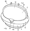
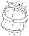
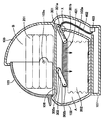
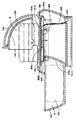
以下、この発明に基づいた加温装置の実施の形態について、図1から図4を参照して説明する。なお、図1は本実施の形態における加温装置100の全体構成(閉鎖状態)を示す斜視図であり、図2は本実施の形態における加温装置100の全体構成(開放状態)を示す斜視図であり、図3は図1中III−III線矢視断面図であり、図4は図2中IV−IV線矢視断面図である。
【0014】
(加温装置100)
図1および図2を参照して、本実施の形態における加温装置100は、上半分がドーム形状の加温装置本体101を有している。この加温装置本体101の内部には、第1被加温対象物を収納するための第1収納領域Aと第2被加温対象物を収納するための第2収納領域Bとを隔離するための隔離壁106が設けられている。
【0015】
加温装置本体101の隔離壁106よりも下側に位置する第1収納領域Aにおいては、P1方向に引出し可能な引出し102が設けられ、この引出し102の内部に、第1被加温対象物を収納可能としている。
【0016】
加温装置本体101の隔離壁106よりも上側に位置する第2収納領域Bにおいては、固定的に設けられる半ドーム壁105と、この半ドーム壁105の内壁に沿って軸103c(図3参照)を回転軸にしてP2方向に開閉可能な半ドーム開閉蓋103が設けられている。
【0017】
半ドーム開閉蓋103の前部にはつまみ103aが設けられ、半ドーム開閉蓋103を閉じた状態においては、このつまみ103aに設けられた係合部材が、加温装置本体101に設けられた係合部に係止し、この係止状態は、加温装置本体101に設けられた解除ピン104により解除可能に設けられている。
【0018】
加温装置100の内部において、図3および図4に示すように、隔離壁106の下端部には加温ヒータ401が設けられている。この加温ヒータ401には、ケーブル402およびコネクタ403が設けられ、外部から電力を供給可能としている。
【0019】
また、加温ヒータ401の後部には、リンクバー301の回動軸301bが連結され、加温ヒータ401の前部には、リンクバー302の回動軸302bが連結されている。リンクバー301の他端部は、隔離壁106の下側に設けられたリブに回動軸301aが連結され、リンクバー302の他端部は、隔離壁106の下側に設けられたリブに回動軸302aが連結されている。このリンクバー301,302は、引出し102の両側に設けられる。
【0020】
ここで、引出し102が加温装置本体101内に収容された状態においては、図3に示すように、加温ヒータ401が自重により下方に降下した状態となる。一方、引出し102を加温装置本体101外に引き出した状態においては、引出し102の後端部がリンクバー301に当接し(図3中Xで囲まれる領域)、引出し102の後端部がリンクバー301を上方に持ち上げる結果、加温ヒータ401が上方に持ち上げられた状態が維持されることになる。
【0021】
(作用・効果)
以上、上記構成からなる加温装置によれば、1つの加温ヒータ401により、第1収納領域Aおよび第2収納領域Bにおいて、2つの育児用品を加温することができる。たとえば、図3および図4に示すように、第1収納領域Aにウエットティッシュ202を配置し、第2収納領域Bに紙おむつ201を配置することにより、おむつ替えのときなど、赤ちゃんを冷たさでびっくりさせることなく、快適な気持ちで、赤ちゃんのおむつ替えを行なうことが可能になる。
【0022】
また、下方に引出し102を配置することにより、ウエットティッシュ202のように、上面側に取出し口が設けられている育児用品であっても、使い勝手を損なうことなく、ウエットティッシュ202の加温を実現させることが可能になる。
【0023】
また、上方に開閉可能な半ドーム開閉蓋103を設けることで、簡単な作業で第2収納領域Bの開閉が行なえ、紙おむつ201の取出しや収納作業も容易に行なうことが可能になる。
【0024】
さらに、加温ヒータ401に昇降機構を設けることにより、引出し102を筐加温装置本体101内に収容している状態においては、加温ヒータ401がウエットティッシュ202に接近することから、ウエットティッシュ202を効果的に暖めることが可能になる。
【0025】
なお、上記実施の形態においては、第1収納領域Aに引出し102、第2収納領域Bに半ドーム開閉蓋103を設ける構成にしたが、いずれの領域にも引出しを設ける構成や、または開閉蓋を設ける構成を採用することも可能である。
【0026】
また、加温ヒータ401の昇降機構についても、リンクバー301,302を用いる構成を採用しているが、その他公知の技術により、引出し102の出し入れに連動した昇降機構を適用することが可能である。
【0027】
また、ウエットティッシュ、紙おむつだけでなく、その他の加温が必要な育児製品に対して用いることが可能である。
【0028】
したがって、今回開示した上記実施の形態はすべての点で例示であって、限定的な解釈の根拠となるものではない。したがって、本発明の技術的範囲は、上記した実施の形態のみによって解釈されるのではなく、特許請求の範囲の記載に基づいて画定される。また、特許請求の範囲と均等の意味および範囲内でのすべての変更が含まれる。
【0029】
【発明の効果】
この発明に基いた加温装置によれば、おむつ替えのときなど、赤ちゃんを冷たさでびっくりさせることなく、快適な気持ちで、赤ちゃんのおむつ替えを行なうことが可能になる。
【図面の簡単な説明】
【図1】本実施の形態における加温装置100の全体構成(閉鎖状態)を示す斜視図である。
【図2】本実施の形態における加温装置100の全体構成(開放状態)を示す斜視図である。
【図3】図1中III−III線矢視断面図である。
【図4】図2中IV−IV線矢視断面図である。
【符号の説明】
100 加温装置、101 加温装置本体、102 引出し、103 半ドーム開閉蓋、103a つまみ、103c 軸、104 解除ピン、105 半ドーム壁、106 隔離壁、301,302 リンクバー、301a,301b,302a,302b 回動軸、401 加温ヒータ、402 ケーブル、403
コネクタ、A 第1収納領域、B 第2収納領域。[0001]
TECHNICAL FIELD OF THE INVENTION
The present invention relates to a heating device, and more particularly, to a heating device capable of warming a diaper, a wet tissue, and other childcare items.
[0002]
[Prior art]
Diapers, wet tissues, etc. used when raising a baby are not problematic when used in the summer, but in the winter, diapers and wet tissues are cold due to outside air, so the baby is cold. The babies sleeping or waking up can be awake because of their coldness. Therefore, as a device for warming a wet tissue, a heating device for a wet tissue disclosed in Japanese Patent Application Laid-Open No. HEI 8-117137 can be mentioned.
[0003]
In this wet tissue heating device, a heater is attached to the upper side of a container for storing the wet tissue, and a tissue outlet is provided at a position corresponding to the opening position of the wet tissue.
[0004]
[Problems to be solved by the invention]
However, in the above-mentioned heating device, there is only one heating area, and since the tissue outlet is on the upper surface side, it is not possible to place other childcare products to be overheated on the upper surface side of the heating device. ing.
[0005]
Accordingly, it is an object of the present invention to provide a heating device which can provide two heating areas for childcare products to be heated.
[0006]
[Means for Solving the Problems]
The heating device according to the present invention is a heating device for storing an object to be heated, the first storage region for storing a first object to be heated, and the first storage region. A second storage area for storing a second object to be heated, separated from the first storage area by an isolation wall above the area, and a first storage area provided near the isolation wall; Heating means for heating the object and the second object to be heated;
[0007]
With this configuration, two childcare articles can be heated in the first storage area and the second storage area by one heating unit. For example, by disposing a wet tissue as a first heated object in the first storage area and disposing a disposable diaper as a second heated object in the second storage area, the baby can be cooled when changing diapers. The baby can be changed with a comfortable feeling without being surprised.
[0008]
In the heating device, preferably, the heating device has a housing provided with the isolation wall in an intermediate area, and the first storage area can be put in and out of the housing in an area below the isolation wall. A drawer member is provided, and a cover member that can be opened and closed is provided in the second storage area in an area above the isolation wall.
[0009]
By arranging the drawer member below, even if the child care product has an outlet on the upper surface side, such as a wet tissue, the first heated object can be used without impairing the usability. It becomes possible to realize heating of the object.
[0010]
Further, by providing a cover member that can be opened and closed at the top, the second storage area can be opened and closed with a simple operation, and, for example, the disposable diaper can be easily taken out and stored.
[0011]
Preferably, in the heating device, between the heating means and the drawing member, when the drawing member is drawn, the heating means rises, and after the drawing member is stored, the drawing member is pulled out. An elevating mechanism for lowering the member into the first storage area is provided.
[0012]
By providing this elevating mechanism, in a state in which the drawer member is housed in the housing, the heating means approaches the first object to be heated, so that the first object to be heated can be effectively moved. It becomes possible to warm.
[0013]
BEST MODE FOR CARRYING OUT THE INVENTION
Hereinafter, an embodiment of a heating device according to the present invention will be described with reference to FIGS. FIG. 1 is a perspective view showing the entire configuration (closed state) of the
[0014]
(Heating device 100)
Referring to FIG. 1 and FIG. 2,
[0015]
In the first storage area A located below the
[0016]
In the second storage area B located above the
[0017]
A
[0018]
As shown in FIGS. 3 and 4, a
[0019]
A rotating
[0020]
Here, in a state in which the
[0021]
(Action / Effect)
As described above, according to the heating device having the above configuration, one
[0022]
In addition, by disposing the
[0023]
Further, by providing the half dome opening /
[0024]
Further, by providing the
[0025]
In the above embodiment, the
[0026]
Although the structure using the link bars 301 and 302 is also used for the elevating mechanism of the
[0027]
Further, it can be used not only for wet tissues and disposable diapers, but also for other childcare products that require heating.
[0028]
Therefore, the above-described embodiment disclosed this time is an example in all respects, and is not a basis for restrictive interpretation. Therefore, the technical scope of the present invention is not interpreted only by the above-described embodiments, but is defined based on the description of the claims. In addition, all changes within the meaning and scope equivalent to the claims are included.
[0029]
【The invention's effect】
ADVANTAGE OF THE INVENTION According to the warming apparatus based on this invention, it becomes possible to change a baby's diaper with a comfortable feeling without surprised by coldness, such as at the time of a diaper change.
[Brief description of the drawings]
FIG. 1 is a perspective view showing an overall configuration (closed state) of a
FIG. 2 is a perspective view showing the overall configuration (open state) of the
FIG. 3 is a sectional view taken along line III-III in FIG.
FIG. 4 is a sectional view taken along line IV-IV in FIG. 2;
[Explanation of symbols]
Connector, A 1st storage area, B 2nd storage area.
Claims (3)
第1被加温対象物を収納するための第1収納領域と、
前記第1収納領域の上方において前記第1収納領域に対して隔離壁によって隔たれた、第2被加温対象物を収納するための第2収納領域と、
前記隔離壁近傍に設けられ、前記第1被加温対象物および前記第2被加温対象物を加温するための加温手段と、
を備える、加温装置。A heating device for storing an object to be heated,
A first storage area for storing a first heated object;
A second storage area for storing a second heated object separated from the first storage area by an isolation wall above the first storage area;
Heating means provided near the isolation wall for heating the first heated object and the second heated object;
A heating device comprising:
前記第1収納領域には、前記隔離壁よりも下方領域において、前記筐体に対して出し入れ可能な引出部材が設けられ、
前記第2収納領域には、前記隔離壁よりも上方領域において、開閉可能なカバー部材が設けられる、請求項1に記載の加温装置。The heating device has a housing including the isolation wall in an intermediate region,
In the first storage area, a drawer member that can be taken in and out of the housing is provided in an area below the isolation wall,
The heating device according to claim 1, wherein a cover member that can be opened and closed is provided in the second storage area in an area above the isolation wall.
Priority Applications (1)
| Application Number | Priority Date | Filing Date | Title |
|---|---|---|---|
| JP2002165266A JP2004014257A (en) | 2002-06-06 | 2002-06-06 | Warming device |
Applications Claiming Priority (1)
| Application Number | Priority Date | Filing Date | Title |
|---|---|---|---|
| JP2002165266A JP2004014257A (en) | 2002-06-06 | 2002-06-06 | Warming device |
Publications (1)
| Publication Number | Publication Date |
|---|---|
| JP2004014257A true JP2004014257A (en) | 2004-01-15 |
Family
ID=30433146
Family Applications (1)
| Application Number | Title | Priority Date | Filing Date |
|---|---|---|---|
| JP2002165266A Pending JP2004014257A (en) | 2002-06-06 | 2002-06-06 | Warming device |
Country Status (1)
| Country | Link |
|---|---|
| JP (1) | JP2004014257A (en) |
Citations (7)
| Publication number | Priority date | Publication date | Assignee | Title |
|---|---|---|---|---|
| JPS5578963A (en) * | 1978-12-07 | 1980-06-14 | Matsushita Seiko Kk | Sterilizing dryer of nursing bottle |
| JPS56173952U (en) * | 1980-05-27 | 1981-12-22 | ||
| JPS58104454U (en) * | 1982-01-08 | 1983-07-15 | 東芝テック株式会社 | link mechanism |
| JPH01181019A (en) * | 1988-01-12 | 1989-07-19 | Sanyo Electric Co Ltd | Cooking device |
| JPH0415471U (en) * | 1990-05-29 | 1992-02-07 | ||
| JPH105030A (en) * | 1996-06-20 | 1998-01-13 | Yoshikawakuni Kogyosho:Kk | Diaper goods housing basket |
| JPH1118989A (en) * | 1997-07-03 | 1999-01-26 | Nippon Dennetsu Co Ltd | Wet tissue heating system |
-
2002
- 2002-06-06 JP JP2002165266A patent/JP2004014257A/en active Pending
Patent Citations (7)
| Publication number | Priority date | Publication date | Assignee | Title |
|---|---|---|---|---|
| JPS5578963A (en) * | 1978-12-07 | 1980-06-14 | Matsushita Seiko Kk | Sterilizing dryer of nursing bottle |
| JPS56173952U (en) * | 1980-05-27 | 1981-12-22 | ||
| JPS58104454U (en) * | 1982-01-08 | 1983-07-15 | 東芝テック株式会社 | link mechanism |
| JPH01181019A (en) * | 1988-01-12 | 1989-07-19 | Sanyo Electric Co Ltd | Cooking device |
| JPH0415471U (en) * | 1990-05-29 | 1992-02-07 | ||
| JPH105030A (en) * | 1996-06-20 | 1998-01-13 | Yoshikawakuni Kogyosho:Kk | Diaper goods housing basket |
| JPH1118989A (en) * | 1997-07-03 | 1999-01-26 | Nippon Dennetsu Co Ltd | Wet tissue heating system |
Similar Documents
| Publication | Publication Date | Title |
|---|---|---|
| US20120131747A1 (en) | Nursing and infant support pillow with accessory unit | |
| US20020093159A1 (en) | Juvenile stroller with cooler | |
| PT1053736E (en) | HEATER DOOR MECHANISM FOR BABY HEATING DEVICE | |
| JP2004014257A (en) | Warming device | |
| CN110192738A (en) | A multifunctional integrated medical bed cabinet | |
| KR200492818Y1 (en) | Cover combined use as a pocket for bag | |
| WO2013166760A1 (en) | Mobile kitchen bag and mobile kitchen component for infant | |
| CA2427934C (en) | Device for preservation and rethermalization of meal trays | |
| JP4473391B2 (en) | Portable wet tissue insulation container | |
| CN218852326U (en) | Nursing trolley for replacing baby diaper | |
| CN100407968C (en) | Built-in heating cooker | |
| CN209171821U (en) | A kind of wall-hung type Baby Care platform | |
| JPH0211033Y2 (en) | ||
| CN214085267U (en) | Ostomy appliance storage box | |
| JP3615863B2 (en) | Sauna equipment | |
| JPH10328251A (en) | Heated type open access door for incubator | |
| CN220424103U (en) | Nursing bed | |
| KR200182798Y1 (en) | Infrared Sauna Machine for and Indiviaual | |
| JP3131381B2 (en) | Sauna equipment | |
| JP7603021B2 (en) | Simple incubator and childcare system equipped with the simple incubator | |
| KR100473408B1 (en) | Air bathtub Apparatus for Lower half of body which is filled with air | |
| CN212729181U (en) | Dining table with function is collected to meal | |
| WO2012074880A1 (en) | Nursing and infant support pillow with accessory unit | |
| CN209694895U (en) | A kind of apparatus for drinking water suitable for gynaecology's sufferer | |
| CN209611895U (en) | A kind of infusion support frame |
Legal Events
| Date | Code | Title | Description |
|---|---|---|---|
| A621 | Written request for application examination |
Free format text: JAPANESE INTERMEDIATE CODE: A621 Effective date: 20041216 |
|
| A131 | Notification of reasons for refusal |
Free format text: JAPANESE INTERMEDIATE CODE: A131 Effective date: 20061031 |
|
| A02 | Decision of refusal |
Free format text: JAPANESE INTERMEDIATE CODE: A02 Effective date: 20070306 |