JP2004010308A - Hoisting device of garbage crane bucket and picking up method of garbage on inclined surface using hoisting device - Google Patents
Hoisting device of garbage crane bucket and picking up method of garbage on inclined surface using hoisting device Download PDFInfo
- Publication number
- JP2004010308A JP2004010308A JP2002168978A JP2002168978A JP2004010308A JP 2004010308 A JP2004010308 A JP 2004010308A JP 2002168978 A JP2002168978 A JP 2002168978A JP 2002168978 A JP2002168978 A JP 2002168978A JP 2004010308 A JP2004010308 A JP 2004010308A
- Authority
- JP
- Japan
- Prior art keywords
- garbage
- bucket
- inclined surface
- hoisting
- wire rope
- Prior art date
- Legal status (The legal status is an assumption and is not a legal conclusion. Google has not performed a legal analysis and makes no representation as to the accuracy of the status listed.)
- Pending
Links
Images


Abstract
Description
【0001】
【産業上の利用分野】
この発明は、ごみ焼却施設において使用されるごみクレ−ンバケットの巻上装置および巻上装置を使用した傾斜面のごみ掴み取り方法に関する。
【0002】
【従来の技術】
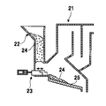
図4に示すように、ごみ焼却炉21には、ごみ投入ホッパー22が設置され、焼却されるごみは、ごみ投入ホッパー22が設置されている建屋の天井部分を走行するごみクレ−ンに装備されたごみクレ−ンバケット(以下、単にバケットという)により、ごみ集積場所からごみ投入ホッパー22まで運ばれ、投入される。
【0003】
そして、ごみ投入ホッパー22に投入されたごみ24は、ごみ投入ホッパー22の底部に設けられたごみ供給装置23により、焼却炉21の火格子25上に押し出され、焼却される。
【0004】
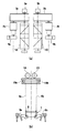
ごみ投入ホッパー22にごみ24を投入するためのごみクレ−ンバケット31は、図5に示すように、ごみクレ−ンによりワイヤロ−プを介して吊り下げられるバケットガ−ダ−32と、バケットガ−ダ−32の左右に一定距離をおいて平行に設けられた1対のピン33aおよび33bと、1対のピン33aおよび33bのそれぞれに、回動可能に接続された掴み爪34aおよび34bと、掴み爪34aおよび34bをお互いに閉じる方向または開く方向に回動させる開閉機構(図示せず)とから構成されている。
【0005】
そして、バケット31の昇降は、バケットのバケットガ−ダ−32の四隅に接続された4本のワイヤロ−プ35を、ごみクレ−ンの巻上装置により巻き上げおよび巻き下げることにより行なわれる。その巻上装置を図6に示す。図6(a)は巻上装置の平面図、図6(b)は巻上装置の正面図である。
【0006】
図6において、41は巻上電動機、42は巻上ブレ−キ、43は巻上減速機、44、45は巻上ドラム、46はパルス発信器である。巻上ドラム44には、バケットの掴み爪34a側に接続した2本のワイヤロ−プ35が巻き取られており、巻上ドラム45には、バケットの掴み爪34b側に接続した2本のワイヤロ−プ35が巻き取られており、バケットの昇降時に、同じ掴み爪側の2本のワイヤロ−プは同じ速度で昇降できるようになっている。これは、同じ掴み爪側の2本のワイヤロ−プの昇降速度が異なることに起因して、バケットが捩れ(回転)ないようにするためである。
【0007】
これら巻上装置は、クレ−ンの横行台車(クラブトロリ−)46上に設置され、横行台車(クラブトロリ−)46と巻上装置との間には、荷重検出器(ロ−ドセル)48が四隅に取付けられおり、バケット31がごみを何トン掴んだかの信号を出力するようになっている。図6中、符号47は横行台車46および巻上装置を動かすための横行車輪である。
【0008】
巻上電動機41を駆動させると、その回転は巻上減速機43を経由して、巻上ドラム44および45を同時に反対方向に回転させる。そして、巻き上げを行なうときには、巻上ドラム44および巻上ドラム45が、それぞれワイヤロ−プ35を内側に巻き込むように回転し、逆に巻き下げを行なうときには、巻上ドラム44および巻上ドラム45が、それぞれワイヤロ−プ35を外側に巻き戻すように回転する。
【0009】
バケット31によりごみ24を掴み取るときには、上述した巻上装置によりワイヤロ−プ35を巻き下げ、ごみ24の山にバケット31を着地させた後、バケット31に内臓された開閉機構により、バケット31の掴み爪34aおよび34bを閉じさせてごみ24を掴み取る。
【0010】
なお、バケット31の着地は、荷重検出器48により、その検出値がバケット31の自重以下になったとき、すなわち、ワイヤロ−プ35に張力が掛からず、バケット31が着地したことによるワイヤロ−プ35のたるんだ瞬間を検知して判断する。
【0011】
そして、バケット31を所定の高さまで上昇させ、バケット31を前記ごみ投入ホッパー22まで移動させ、前記開閉機構によりバケット31の掴み爪34aおよび34bを開いて、ごみ24を投入ホッパー22に投入する。
【0012】
【発明が解決しようとする課題】
上述した従来のごみ投入用のバケットで、ごみを掴み取るに際しては、次のような問題点がある。
【0013】
焼却炉で焼却する前のごみは、焼却工場に設けられたコンクリ−ト製のごみピットに収容されているが、収容されたごみの山は必ずしも平らにはならず、特に外部からごみを運搬してくるごみ運搬車が、ごみをごみピットに投入する付近のごみの山は、傾斜した状態となっている。
【0014】
図7は上述したような傾斜したごみの山にバケットを着地させ、ごみを掴みとるまでの手順を示す図である。図7(a)は、前述した巻上装置の巻上ドラム44および45を矢印の方向に回転させて、それぞれの巻上ドラムに巻き取られているワイヤロ−プ35aおよび35bを巻き戻して、掴み爪34aおよび34bを開いている状態のバケット31を、ごみの山に着地させる直前の状態を示す。
【0015】
図7(b)は、ごみ24の山の山側に掴み爪34aが着地し、かつ掴み爪34bをごみ24の山の谷側に着地させようとしている状態を示す。バケット31でごみ24を掴むためには、バケット31を完全に着地させ、その重量でごみ24の山に両方の掴み爪を食い込ませた上で、掴み爪を閉じる必要がある。完全に着地していない状態で掴み爪を閉じても、定められた量のごみ24を掴み取ることはできない。
【0016】
掴み爪34aが着地している状態で、さらに掴み爪34bを着地させるために、さらにワイヤロ−プ35aおよび35bを巻き戻すので、すでに着地している掴み爪34a側のワイヤロ−プ35aは、図に示すようなたるみ(たるみ部をAで示す)が発生する。
【0017】
ごみ24を定められた量掴むために、さらにワイヤロ−プ35aおよび35bを巻き戻していくと、図7(c)に示すように、バケット31は荷重検出器48からの着地信号が出るまでは、ごみ24の山の傾斜に沿って谷側に滑り落ちる。このため、たるんでいたワイヤロ−プ35aが急に引張られて、ワイヤロ−プ35aには大きな張力が発生する。
【0018】
従来の巻上装置でバケット31の昇降を毎日行っていると、上述したような張力が繰り返し作用し、ワイヤロ−プの寿命が著しく低下し、バケットとの接続部近傍で切断する可能性が高まってくる。また、バケット31が滑り落ちるので、作業能率も低下する。
【0019】
この発明は、上述したような従来技術の問題点を解消するためになされたものであり、ごみの山に傾斜面が形成されていても、バケットを吊っているワイヤロ−プに繰り返し張力が作用せず、かつバケットが傾斜面で滑り落ちないので、作業能率が向上するごみバクレ−ンケットの巻上装置を提供することを目的としている。
【0020】
【課題を解決するための手段】
この発明に係るごみクレ−ンバケットの巻上装置は、天井走行クレ−ンに積載され、ごみクレ−ンバケットの左右に連結されたワイヤロ−プを、別々の巻取ドラムに巻き取り、前記ごみバケットを左右のバランスとりながら昇降させるごみクレ−ンバケットの巻上装置において、前記別々の巻取ドラムの駆動を、それぞれ単独の駆動手段で行うようにしたものである。
【0021】
本発明に係るごみクレ−ンバケットの巻上装置は、ごみクレ−ンバケットの左右に連結されたワイヤロ−プを、それぞれ単独に巻き取ることができるので、ごみの山に傾斜面が形成されていても、傾斜面の傾斜に合わせて、ごみクレ−ンバケットの左右の掴み爪を着地させることができる。
【0022】
また、ごみクレ−ンバケットの左右の掴み爪を、ごみの傾斜面と逆の傾斜となるように傾けることにより、傾斜面を水平にならすことができる。
【0023】
また、この発明に係る傾斜面のごみ掴み取り方法は、次の(1)〜(4)の工程でごみを掴み取るものである。
(1)傾斜面の山側に位置する前記ごみクレ−ンバケットの掴み爪が、前記傾斜面に着地するまで、山側に位置する掴み爪と谷側に位置する掴み爪との高さを同じ高さに保持しながら、ごみクレ−ンバケットのワイヤロ−プを巻き下げ、山側に位置する掴み爪が傾斜面に着地したときに、山側に位置する掴み爪側のワイヤロ−プの巻き下げを停止する工程。
(2)山側に位置する掴み爪側のワイヤロ−プの巻き下げを停止した状態で、傾斜面の谷側に位置するごみクレ−ンバケットの掴み爪が、前記傾斜面に着地するまで、谷側に位置する掴み爪側のワイヤロ−プの巻き下げる工程。
(3)着地した谷側に位置する掴み爪側のワイヤロ−プを巻き上げ、同時に山側に位置する掴み爪をごみの山に食い込ませ、かつ掴み爪を閉じる動作も併用して、ごみの傾斜面を水平にならす工程
(4)ごみがほぼ平らになった後で、山側および谷側のワイヤロ−プの均衡を図った後、両方の掴み爪を閉じてごみを掴み、ごみクレ−ンバケットを巻き上げる工程。
【0024】
この発明に係る傾斜面のごみ掴み取り方法においては、上記(1)〜(4)の工程でごみを掴み取るので、バケットがごみの山の傾斜面を滑り落ちて、たるんだワイヤロ−プに大きな張力が発生することがないので、ワイヤロ−プの寿命を延ばすことができる。
【0025】
また、ごみクレ−ンバケットが傾斜面に沿って滑り落ちることがないので、ごみを掴み取る作業の作業能率が向上する。
【0026】
【発明の実施の形態】
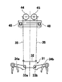
本発明の実施の形態を図面を参照して説明する。図1は本発明のごみクレ−ンバケットの巻上装置の説明図であり、(a)は巻上装置の平面図であり、(b)は巻上装置の巻上ドラムに巻き取られるごみクレ−ンバケットの正面図である。
【0027】
図において、1A、1Bは巻上ドラム、2a、2bは巻上電動機、3a、3bは減速機、4a、4bは巻上ブレ−キ、5a、5bはパルス発信器、6a、6bはワイヤロ−プ、7はバケット、8はバケットガ−ダ−、9a、9bはバケットの掴み爪、10a、10bは荷重検出器(ロ−ドセル)である。
【0028】
この巻上装置は、バケット7のバケットガ−ダ−8を吊り下げているワイヤロ−プのうち、左側の掴み爪9aに近い側のワイヤロ−プ6a(図1では1本しか示していないが、実際には図面と直交する方向に一定間隔をおいて2本接続されている)を巻き上げる巻上ドラム1Aと、右側の掴み爪9bに近い側のワイヤロ−プ6b(ワイヤロ−プ6aと同じように、2本接続されている)を巻き上げる巻上ドラム1Bとを備えており、それぞれ単独に巻き上げ、巻き下げ動作が行えるようになっている。
【0029】
この巻上装置を詳述すると、巻上ドラム1Aは、巻上電動機2aを駆動させ、その回転を巻上減速機3aを経由して伝達することにより回転される。
巻上電動機2aは正転および逆転することが可能であるので、巻上ドラム1Aを正転および逆転させて、ワイヤロ−プ6aの巻上および巻き下げを行なうことができる。また、巻上ブレ−キ4aにより任意の高さにクレ−ンバケット7を保持することができる。
【0030】
巻上ドラム1Bは、巻上電動機2bを駆動させ、その回転を巻上減速機3bを経由して伝達することにより回転される。巻上電動機2bは正転および逆転することが可能であるので、巻上ドラム1Bを正転および逆転させて、ワイヤロ−プ6bの巻上および巻き下げを行なうことができる。また、巻上ブレ−キ4bにより任意の高さにバケット7を保持することができる。
【0031】
図2は、上述した本発明の巻上装置の制御系統図である。バケット7のバケットガ−ダ−内部に取付けた内部傾斜角センサ−11からの信号、巻上ドラム1Aのワイヤロ−プ6aの長さを検出するパルス発信器5aの信号、巻上ドラム1Bのワイヤロ−プ6bの長さを検出するパルス発信器5bの信号、および荷重検出器10a、10bの荷重信号が、それぞれごみクレ−ンのシステム制御盤12に送られる。
【0032】
そして、内部傾斜角センサ−11からの信号により、バケット7の傾き状態を把握し、巻上ドラム1Aおよび1Bのうちのどの巻上ドラムを回転させるかを判断し、巻上電動機2aまたは2bに必要な指示が与えられる。
【0033】
同時に、左右それぞれのワイヤロ−プ6aおよび6bの繰り出し長さを、パルス発信器5aおよび5bからの信号により把握し、巻上の停止および回転するドラムの切替え等の制御が行なわれる。
【0034】
次に、上述した巻上装置を使用して、傾斜面が形成されたごみの山から、バケット7によりごみを掴み取る方法を、図3により説明する。
(1)図3(a)に示すように、山側の掴み爪9aがごみの山100に着地した時に(荷重検出器10a、10bの荷重信号が、バケット7の自重よりも軽くなったことにより検知した時に)、巻上ドラム1Aの巻き下げ方向の回転を停止させて、ワイヤロ−プ6aがたるまないようにする。
(2)図3(b)に示すように、山側の巻上ドラム1Aの巻き下げ方向の回転を停止させた後も、谷側の巻上ドラム1Bの巻き下げ方向の回転を継続させて、谷側の掴み爪9bをごみの山100に着地させ、巻上ドラム1Bの巻き下げ方向の回転を停止させる。
(3)図3(c)に示すように、谷側の巻上ドラム1Bを巻き上げ方向に回転させて、着地した谷側に位置する掴み爪9b側のワイヤロ−プ6bを巻き上げる。
(4)同時に、掴み爪の閉じる動作も併用して、ごみ100をくずす作業を行い、図3(d)に示すように、ごみ100の傾斜面が水平にならされる。
(5)ごみが平らになった後で、山側、谷側のワイヤロ−プ6aおよび6b
の均衡を図った後、掴み9aおよび9bを閉じてごみを掴み、クレ−ンバケット7を巻き上げる。
【0035】
【発明の効果】
本発明により、バケットがごみの山の傾斜面を滑り落ちて、たるんだワイヤロ−プに過大な張力が発生することがないので、ごみクレ−ンバケットのワイヤロ−プの寿命が延びるとともに、ごみを掴み取る作業の作業能率も向上する。
【図面の簡単な説明】
【図1】本発明のごみクレ−ンバケットの巻上装置の説明図であり、(a)は巻上装置の平面図であり、(b)は巻上装置の巻上ドラムに巻き取られるごみクレ−ンバケットの正面図である。
【図2】本発明の巻上装置の制御系統図である。
【図3】(a)〜(d)は本発明の傾斜面のごみ掴み取り方法の工程を示す図である。
【図4】ごみ焼却炉の構成を示す構成図である。
【図5】ごみクレ−ンバケットの正面図である。
【図6】従来のごみクレ−ンバケットの巻上装置の説明図であり、(a)は巻上装置の平面図、(b)は巻上装置の正面図である。
【図7】(a)〜(c)は従来の傾斜面のごみ掴み取り方法の工程を示す図である。
【符号の説明】
1A、1B 巻上ドラム
2a、2b 巻上電動機
3a、3b 減速機
4a、4b 巻上ブレ−キ
5a、5b パルス発信器
6a、6b ワイヤロ−プ
7 ごみクレ−ンバケット
8 吊下部材
9a、9b 掴み爪
10a、10b 荷重検出器
11 内部傾斜角センサ−
12 システム制御盤[0001]
[Industrial applications]
The present invention relates to a refuse crane bucket hoisting device used in a refuse incineration facility and a method for gripping dirt on an inclined surface using the hoisting device.
[0002]
[Prior art]
As shown in FIG. 4, a
[0003]
Then, the
[0004]
As shown in FIG. 5, a
[0005]
The lifting and lowering of the
[0006]
In FIG. 6, 41 is a hoisting motor, 42 is a hoisting brake, 43 is a hoisting reducer, 44 and 45 are hoisting drums, and 46 is a pulse transmitter. Two
[0007]
These hoisting devices are installed on a
[0008]
When the hoisting
[0009]
When the
[0010]
Note that the landing of the
[0011]
Then, the
[0012]
[Problems to be solved by the invention]
There are the following problems when catching refuse with the above-described conventional refuse bucket.
[0013]
Waste before being incinerated in an incinerator is stored in a concrete waste pit provided in the incineration plant, but the pile of stored waste is not always flat, and especially when the waste is transported from outside. The pile of garbage near the incoming garbage truck that throws garbage into the garbage pit is in an inclined state.
[0014]
FIG. 7 is a diagram showing a procedure from landing of the bucket on the inclined garbage pile as described above until the garbage is caught. FIG. 7A shows that the hoisting
[0015]
FIG. 7B shows a state in which the grasping
[0016]
With the gripping
[0017]
When the wire ropes 35a and 35b are further rewound in order to grasp the
[0018]
If the
[0019]
SUMMARY OF THE INVENTION The present invention has been made to solve the above-described problems of the prior art, and even if a slope is formed on a refuse mountain, repeated tension acts on a wire rope suspending a bucket. It is an object of the present invention to provide a refuse buckle bucket hoisting device which improves the work efficiency because the bucket does not slide down on the inclined surface.
[0020]
[Means for Solving the Problems]
The garbage crane bucket hoisting device according to the present invention winds wire ropes mounted on an overhead traveling crane and connected to left and right sides of the garbage crane bucket on separate winding drums. In a garbage crane bucket hoisting apparatus for raising and lowering while maintaining the right and left balance, the separate winding drums are driven by independent driving means.
[0021]
The garbage crane bucket hoisting device according to the present invention can independently wind the wire ropes connected to the left and right of the garbage crane bucket. Also, the left and right gripping claws of the garbage crane bucket can be landed according to the inclination of the inclined surface.
[0022]
Also, the inclined surfaces can be leveled by tilting the left and right gripping claws of the garbage crane bucket so that the inclined surfaces are opposite to the inclined surfaces of the dust.
[0023]
In addition, the method for grabbing dirt on an inclined surface according to the present invention is to grab dirt in the following steps (1) to (4).
(1) The height of the gripping claw located on the mountain side and the gripping claw located on the valley side are the same height until the gripping claws of the dust crane bucket located on the mountain side of the inclined surface land on the inclined surface. Step of lowering the wire rope of the garbage crane bucket while holding the wire rope, and stopping the lowering of the wire rope on the grip claw side located on the mountain side when the grip claw located on the mountain side lands on the inclined surface. .
(2) In the state where the lowering of the wire rope on the gripping claw side located on the mountain side is stopped, the valley side is reached until the gripping claws of the garbage crane bucket located on the valley side of the inclined surface land on the inclined surface. Step of lowering the wire rope on the side of the gripping claw located at the position shown in FIG.
(3) The wire rope on the gripping claw side located on the valley side where the landing is wound up, and at the same time, the gripping claw located on the mountain side is bitten into the garbage pile, and the operation of closing the gripping claw is also used in combination with the inclined surface of the dust. (4) After the dust is almost flat, balance the wire ropes on the mountain side and the valley side, close both gripping claws to grasp the dust, and roll up the dust crane bucket Process.
[0024]
In the method for grabbing dirt on the inclined surface according to the present invention, the dirt is grabbed in the above steps (1) to (4), so that the bucket slides down the inclined surface of the dirt mountain and is large in the slack wire rope. Since no tension is generated, the life of the wire rope can be extended.
[0025]
In addition, since the dust crane bucket does not slide down along the inclined surface, the work efficiency of the task of picking up dust is improved.
[0026]
BEST MODE FOR CARRYING OUT THE INVENTION
An embodiment of the present invention will be described with reference to the drawings. 1A and 1B are explanatory views of a hoisting device for a garbage crane bucket according to the present invention, wherein FIG. 1A is a plan view of the hoisting device, and FIG. It is a front view of a negative bucket.
[0027]
In the figures, 1A and 1B are hoisting drums, 2a and 2b are hoisting motors, 3a and 3b are reduction gears, 4a and 4b are hoisting brakes, 5a and 5b are pulse generators, and 6a and 6b are wire-wrappers. Reference numeral 7 denotes a bucket, 8 denotes a bucket guarder, 9a and 9b denote bucket gripping claws, 10a and 10b denote load detectors (load cells).
[0028]
In this hoisting apparatus, of the wire ropes suspending the bucket girder 8 of the bucket 7, a
[0029]
The hoisting device will be described in detail. The hoisting
Since the hoisting
[0030]
The hoist
[0031]
FIG. 2 is a control system diagram of the hoisting device of the present invention described above. A signal from an internal
[0032]
Then, based on a signal from the internal
[0033]
At the same time, the feeding lengths of the left and
[0034]
Next, a method of using the above-described hoisting device to grab dust with the bucket 7 from a pile of dust on which an inclined surface is formed will be described with reference to FIG.
(1) As shown in FIG. 3A, when the
(2) As shown in FIG. 3B, even after the rotation of the hill-
(3) As shown in FIG. 3 (c), the winding
(4) At the same time, the operation of breaking the
(5) After the dust is flattened, the top and
After the balance has been achieved, the
[0035]
【The invention's effect】
According to the present invention, since the bucket does not slide down the inclined surface of the refuse mountain and excessive tension is not generated in the slack wire rope, the life of the wire rope of the refuse crane bucket is extended and the refuse is removed. The work efficiency of the grabbing work is also improved.
[Brief description of the drawings]
FIG. 1 is an explanatory view of a hoisting device for a garbage crane bucket according to the present invention, wherein (a) is a plan view of the hoisting device, and (b) is refuse to be taken up by a hoisting drum of the hoisting device. It is a front view of a crane bucket.
FIG. 2 is a control system diagram of the hoisting device of the present invention.
3 (a) to 3 (d) are views showing the steps of a method for grabbing dirt on an inclined surface according to the present invention.
FIG. 4 is a configuration diagram showing a configuration of a refuse incinerator.
FIG. 5 is a front view of a garbage crane bucket.
FIG. 6 is an explanatory view of a conventional hoisting device for a garbage crane bucket, wherein (a) is a plan view of the hoisting device and (b) is a front view of the hoisting device.
7 (a) to 7 (c) are views showing steps of a conventional dirt grabbing method for an inclined surface.
[Explanation of symbols]
1A,
12 System control panel
Claims (2)
(1)傾斜面の山側に位置する前記ごみクレ−ンバケットの掴み爪が、
前記傾斜面に着地するまで、山側に位置する掴み爪と谷側に位置する掴み爪との高さを同じ高さに保持しながら、ごみクレ−ンバケットのワイヤロ−プを巻き下げ、山側に位置する掴み爪が傾斜面に着地したときに、山側に位置する掴み爪側のワイヤロ−プの巻き下げを停止する工程。
(2)山側に位置する掴み爪側のワイヤロ−プの巻き下げを停止した状態で、傾斜面の谷側に位置するごみクレ−ンバケットの掴み爪が、前記傾斜面に着地するまで、谷側に位置する掴み爪側のワイヤロ−プの巻き下げる工程。
(3)着地した谷側に位置する掴み爪側のワイヤロ−プを巻き上げ、同時に山側に位置する掴み爪をごみの山に食い込ませ、かつ掴み爪を閉じる動作も併用して、ごみの傾斜面を水平にならす工程
(4)ごみがほぼ平らになった後で、山側および谷側のワイヤロ−プの均衡を図った後、両方の掴み爪を閉じてごみを掴み、ごみクレ−ンバケットを巻き上げる工程。A method for picking up dirt on an inclined surface using the garbage crane bucket hoisting device according to claim 1, wherein the dirt is picked up in the following steps (1) to (4). How to grab garbage.
(1) The gripping claws of the garbage crane bucket located on the mountain side of the inclined surface,
Until landing on the inclined surface, the wire rope of the garbage crane bucket is lowered while maintaining the height of the gripping claw located on the mountain side and the gripping claw located on the valley side at the same height, and is positioned on the mountain side. Stopping the lowering of the wire rope on the side of the gripping claw located on the mountain side when the gripping claw touches the inclined surface.
(2) In the state where the lowering of the wire rope on the gripping claw side located on the mountain side is stopped, the valley side is reached until the gripping claws of the garbage crane bucket located on the valley side of the inclined surface land on the inclined surface. Step of lowering the wire rope on the side of the gripping claw located at the position shown in FIG.
(3) The wire rope on the gripping claw side located on the valley side where the landing is wound up, and at the same time, the gripping claw located on the mountain side is bitten into the garbage pile, and the operation of closing the gripping claw is also used in combination with the inclined surface of the dust. (4) After the dust is almost flat, balance the wire ropes on the mountain side and the valley side, close both gripping claws to grasp the dust, and roll up the dust crane bucket Process.
Priority Applications (1)
| Application Number | Priority Date | Filing Date | Title |
|---|---|---|---|
| JP2002168978A JP2004010308A (en) | 2002-06-10 | 2002-06-10 | Hoisting device of garbage crane bucket and picking up method of garbage on inclined surface using hoisting device |
Applications Claiming Priority (1)
| Application Number | Priority Date | Filing Date | Title |
|---|---|---|---|
| JP2002168978A JP2004010308A (en) | 2002-06-10 | 2002-06-10 | Hoisting device of garbage crane bucket and picking up method of garbage on inclined surface using hoisting device |
Publications (1)
| Publication Number | Publication Date |
|---|---|
| JP2004010308A true JP2004010308A (en) | 2004-01-15 |
Family
ID=30435740
Family Applications (1)
| Application Number | Title | Priority Date | Filing Date |
|---|---|---|---|
| JP2002168978A Pending JP2004010308A (en) | 2002-06-10 | 2002-06-10 | Hoisting device of garbage crane bucket and picking up method of garbage on inclined surface using hoisting device |
Country Status (1)
| Country | Link |
|---|---|
| JP (1) | JP2004010308A (en) |
Cited By (4)
| Publication number | Priority date | Publication date | Assignee | Title |
|---|---|---|---|---|
| JP2011058167A (en) * | 2009-09-07 | 2011-03-24 | Penta Ocean Construction Co Ltd | Dredging unit and dredging method |
| JP2014118230A (en) * | 2012-12-13 | 2014-06-30 | Sumitomo Heavy Industries Material Handling Systems Co Ltd | Bridge type unloader and control method of the same |
| CN112758831A (en) * | 2021-03-02 | 2021-05-07 | 河南合力起重机械有限公司 | Special crane for garbage power generation with component detection function |
| JP7467792B2 (en) | 2021-01-12 | 2024-04-16 | 株式会社日立プラントメカニクス | How to correct gripping position with an automatic crane |
-
2002
- 2002-06-10 JP JP2002168978A patent/JP2004010308A/en active Pending
Cited By (4)
| Publication number | Priority date | Publication date | Assignee | Title |
|---|---|---|---|---|
| JP2011058167A (en) * | 2009-09-07 | 2011-03-24 | Penta Ocean Construction Co Ltd | Dredging unit and dredging method |
| JP2014118230A (en) * | 2012-12-13 | 2014-06-30 | Sumitomo Heavy Industries Material Handling Systems Co Ltd | Bridge type unloader and control method of the same |
| JP7467792B2 (en) | 2021-01-12 | 2024-04-16 | 株式会社日立プラントメカニクス | How to correct gripping position with an automatic crane |
| CN112758831A (en) * | 2021-03-02 | 2021-05-07 | 河南合力起重机械有限公司 | Special crane for garbage power generation with component detection function |
Similar Documents
| Publication | Publication Date | Title |
|---|---|---|
| CN1071704C (en) | Control system for rope bucket | |
| US5713477A (en) | Method and apparatus for controlling and operating a container crane or other similar cranes | |
| WO2014091780A1 (en) | Grab bucket hoisting control device, unloader provided with grab bucket hoisting control device, and grab bucket hoisting control method | |
| JP2011219226A (en) | Ropeway device | |
| JP2004010308A (en) | Hoisting device of garbage crane bucket and picking up method of garbage on inclined surface using hoisting device | |
| JP2011213461A (en) | Crane | |
| CN209505542U (en) | A kind of construction material carrier | |
| JP2006027783A (en) | Control device of automatic crane for garbage disposal plant | |
| JP4149082B2 (en) | Automatic crane operation method in grooving work in garbage pit | |
| JPS5832138B2 (en) | Long object and sleeper cargo handling equipment | |
| JP2004284736A (en) | Overhead travelling crane | |
| JP2655789B2 (en) | Automatic scrap handling by grab bucket | |
| JPS5936095A (en) | Method of controlling quantity of grasp of grab bucket | |
| CN212050229U (en) | Bridge type grab crane protection device | |
| JPH08133669A (en) | Method for controlling overhead travelling | |
| JPS6010997B2 (en) | How to prevent a bucket crane from falling over | |
| JPH01247393A (en) | Method and device for bucket grasping of crane with rope type bucket | |
| CN216272736U (en) | Automatic slag hoisting system | |
| JP7423882B2 (en) | Bucket grip control method | |
| JP6874946B2 (en) | Quay crane | |
| CN213890028U (en) | Automatic control system that snatchs of rubbish multiple spot | |
| JP4619672B2 (en) | Overhead crane with temporary hopper cart | |
| WO2022095228A1 (en) | Unmanned crane provided with automatic unhooking and hooking apparatus, and operating method therefor | |
| JP2018203416A (en) | Quay crane and motor capacity determination method for quay crane | |
| JP6628318B2 (en) | Overhead crane with grab bucket |