JP2004009392A - Mold for molding substrate for information recording disk, molding method therefor and substrate for information recording disk - Google Patents
Mold for molding substrate for information recording disk, molding method therefor and substrate for information recording disk Download PDFInfo
- Publication number
- JP2004009392A JP2004009392A JP2002163669A JP2002163669A JP2004009392A JP 2004009392 A JP2004009392 A JP 2004009392A JP 2002163669 A JP2002163669 A JP 2002163669A JP 2002163669 A JP2002163669 A JP 2002163669A JP 2004009392 A JP2004009392 A JP 2004009392A
- Authority
- JP
- Japan
- Prior art keywords
- mold
- substrate
- inner peripheral
- stamper
- molding
- Prior art date
- Legal status (The legal status is an assumption and is not a legal conclusion. Google has not performed a legal analysis and makes no representation as to the accuracy of the status listed.)
- Pending
Links
Images


Abstract
Description
【0001】
【発明の属する技術分野】
本発明は、情報記録ディスク用基板の成形用金型、成形方法及びその成形方法で作製された基板に関し、特に、光ディスク用の樹脂製基板の成形用金型、成形方法及びその成形方法で作製された基板に関する。
【0002】
【従来の技術】
近年、コンピュータ用の情報のみならず、音楽や静止画像、動画像などの情報がディジタル化され、取り扱う情報量が極めて増大している。それに伴い、これらの情報を保存するための光ディスクは大容量化が望まれている。この要望に応えるために、従来のCD−RやCD−RWに比べて7倍以上の容量を有するDVD−RAMやDVD−RWなどの光ディスクが既に製品化されている。
【0003】
光ディスクは樹脂製基板上に記録層、反射層、保護層などを順次積層して作製される。光ディスクの樹脂製基板は、一対の金型で画成されたキャビティ内に溶融した熱可塑性樹脂を射出して成形される。
【0004】
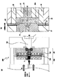
光ディスク用基板の射出成形方法について、図9を用いて説明する。射出成形機900は、図9(a)に示すように、主に固定金型901と、可動金型902と、固定金型901の型締め方向側の端面を支持する固定プラテン102と、可動金型902の型開き方向側の端面を支持する固定プラテン104と、固定金型901を支持するとともに軸AXに沿った可動金型902及び可動プラテン104の移動を支持する支持部903とで構成されている。可動金型902と固定金型901は、軸AXと同軸状に対向して配置されており、それらの間にキャビティ100が画成される。ここでは、図9(a)に示すように、可動金型902の中心に設けられている円筒状のカットパンチ95の中心軸を軸AXとして示した。また、図9(a)中の矢印に示すように、可動金型902が軸AXに沿って固定金型901から離れる方向を型開き方向とし、その逆方向を型締め方向と呼ぶ。
【0005】
可動金型902の固定金型901と対向する可動鏡面97には、図9(a)に示すように、スタンパ90が固定されている。スタンパ90の外周部は図示しないエアバキューム溝から真空吸着等によって固定され、スタンパ90の内周部は、図9(b)に示すように、スタンパ押さえ99のツメ99Aにより固定されている。このツメ99Aの厚みは強度を確保するために0.1mm〜0.2mm程度の厚みを有する。
【0006】
上記構成の射出成形機900の動作を図9を用いて説明する。まず、ノズル103から射出された溶融樹脂はスプールブッシュ91内に形成された断面がテーパー状の通路及びゲート101を通ってキャビティ100内に流れ込む。溶融樹脂がキャビティ100内に充填されると、可動プラテン104内に収容されている突き出しロッド105によりカットパンチ95がスプールブッシュ91に向かって押し出される。そして、カットパンチ95の先端部95Aが固定ブッシュ92内に挿入されるまで押し出されると、キャビティ100のゲート101が遮断され(以下、ゲートシールと言う)、光ディスク用基板の内周穴が成形される。ゲートシールされたキャビティ100内の溶融樹脂は、可動金型902により冷却されながら型締めされる。冷却後、可動金型902が軸AXに沿って型開き方向に移動し、固化した成形基板が固定鏡面93から剥離される。次いで、エジェクター96を軸AXに沿って型締め方向に移動させて成形基板を型締め方向に押し出し、成形基板を可動鏡面97から離型する。こうして光ディスク用基板が得られる。
【0007】
【発明が解決しようとする課題】
ところで、光ディスクにおいても、青色レーザーと高NAレンズを用いて光スポットサイズを微小化して、高密度記録を行う研究が盛んに行われている。このような高密度記録に伴い光ディスクのトラックピッチが一層狭くなるため、光ビームを所望のトラックに追従させるためのトラッキングを一層高精度に行う必要がある。トラッキングを阻害する要因として、光ディスク用基板の偏芯が挙げられる。
【0008】
従来の射出成形方法では、様々な変動要因の積み重ねによりディスク用基板の低偏芯化に限界があった。上述したように光ディスク用基板の内周穴は、カットパンチ95を可動金型本体98内で軸AXに沿って移動させて、固定金型本体94の固定ブッシュ92内に挿入させてキャビティ100をゲートシールすることにより成形される。カットパンチ95及び固定ブッシュ91の中心軸の位置精度は、それぞれ可動金型本体98及び固定金型本体94の加工精度の誤差や熱膨張率の差などにより大きく影響され、これにより成形基板に偏芯が生じる。また、型締めの際には、図9(a)に示した可動金型本体98と固定金型本体94のガイドリング107及び108のテーパー部の嵌合等により調芯されるが、可動プラテン104及び固定プラテン102の平行度により両金型の偏芯精度が影響を受ける。さらに、ガイドリング107及び108などの金型調芯部材の熱膨張率の差などによっても偏芯が生じる。図9に示すような従来の射出成形機900では、これらの累積誤差により偏芯が大きくなり、状況に応じて随時調芯しなければならないという問題があった。
【0009】
また、図9(b)に示すように、スタンパ90の内周部はスタンパ押さえ99のツメ99Aにより可動鏡面97に固定されている。このツメ99Aはキャビティ100内に突出しているために、成形された基板の内周近傍の表面には、ツメ99Aの形状に対応した凹部が形成される。この凹部により信号記録が可能な最内周半径が制限され、記録容量も制限されるという問題があった。また、ツメ99Aの厚みは強度を確保するために0.1mm〜0.2mm程度必要であり、ツメ99Aの厚みにより基板の厚みもまた制限されるという問題があった。
【0010】
さらに、ツメ99Aは、溶融樹脂がキャビティ100に流れ込む際、ツメ99Aの先端部近傍にエアがたまり易くなるので、得られた基板上にフローマークを生じさせる要因になる。また、色素材料等を基板上に塗布する際には、ツメ99Aにより生じた凹部の外側から塗布する必要が生じるので、基板上に均一な膜厚を形成するのに問題があった。これらの問題を解決する一つの方法が、特開2002−18903が開示されている。この文献では、基板の内周近傍の表面を平滑な面にするために、スタンパ内周穴の内壁をテーパー状にして、その部分をスタンパ押さえで保持する方法が提案されている。
【0011】
本発明は、上記従来技術の問題を解決するものであって、その第1の目的は、偏芯が生じない光ディスク用基板を成形するための成形金型及び成形方法を提供することである。そして、本発明の第2の目的は、光ディスク用基板の内周近傍の表面に不要な凹部を生じさせずに、内周近傍の表面が平滑な面である光ディスク用基板を作製するための成形金型及び成形方法を提供することである。
【0012】
【課題を解決するための手段】
本発明の第1の態様に従えば、内周穴を有する情報記録ディスク用基板を成形するための金型であって、溶融樹脂が射出されるキャビティを画成する一対の金型と、上記金型の一方に固定して設けられた凸部と、上記金型の他方に設けられ、上記凸部と嵌合することによって上記内周穴を画成する凹部とを備えた成形用金型が提供される。
【0013】
本発明の成形金型では、偏芯を生じさせる原因となっていた独立可動のカットパンチを用いないで、金型202及び201にそれぞれ固定された凸部25及び凹部を用いて基板の内周穴を成形するので、内周穴に対するディスクの偏芯を極めて低く抑えることができる。即ち、本発明の成形金型では、偏芯の要因がスタンパ90の内周穴の形成時に発生する偏芯と、凸部25とスタンパ90内周穴のクリアランスにより生じる偏芯のみとなるので、内周穴に対して同軸性が極めて高いディスク状基板を歩留まり良く作製することができる。得られた基板の偏芯は、10μm(P−P)以下となる。なお、本文中における基板の偏芯とは、基板の内周穴の中心と、基板表面に形成された情報記録領域の内周及び外周円の中心とのズレ量を言う。
【0014】
また、本発明の成形金型では、図2に示すように、スタンパ90の内周部がスタンパ押さえのツメを用いることなく、基板の内周穴を成形するための凸部25により保持されているので、基板の内周部から外周部に渡る全ての領域の表面はスタンパのパターンを転写することで形成される。その結果、図1に示すように、基板の内周穴11の内周部10aから信号領域12の最内周部までの領域13に、段差(スタンパ押さえのツメ跡を含む)やバリの無い平滑な面の基板を作製することが出来る。従って、本発明の成形金型を用いると、基板の内周部まで情報記録が可能となるので、基板の記録情報量を増加させることが出来る。また、従来使われていたスタンパ押さえのツメによる不要な凹部は形成されないので、基板の一層の薄肉化が可能になるだけでなく、色素材料等のスピン塗布の際に、基板上に均一な膜厚を容易に形成することができる。
【0015】
本発明の第2の態様に従えば、射出成形法による情報記録ディスク用基板の成形方法であって、第一金型の中央部に固定された凸部及び該凸部と嵌合する第二金型の中央部に設けられた凹部をそれぞれ有する第一金型及び第二金型により画成されたキャビティに溶融樹脂を射出する工程と、上記溶融樹脂を上記第一金型及び第二金型で圧縮する工程と、上記溶融樹脂を冷却して固化させる工程とを備え、上記圧縮工程において上記凸部と上記凹部が嵌合することによって、上記基板の内周穴が画成される成形方法が提供される。
【0016】
本発明の第2の態様の成形方法を、図2に示した成形金型を例にして説明する。まず、一対の金型201及び202で画成されたキャビティ100内に溶融樹脂を射出する。樹脂充填後、どちらか一方の金型を軸AXに沿って可動させてキャビティ100内の溶融樹脂を圧縮する。この際、金型202の中央部に固定された凸部25と金型201の中央部に設けられた凹部22が嵌合することによりキャビティがゲートシールされ、基板の内周穴が形成される。その後、冷却して樹脂を固化すると情報記録ディスク用基板が得られる。本発明の成形方法では、基板の内周穴を成形するための部材である凸部25は、常に金型202に固定されているので、第1の態様で説明したように、非常に偏芯が少なく、内周穴に対して同軸性が極めて高いディスク状基板を歩留まり良く作製することができる。
【0017】
本発明の第3の態様に従えば、内周穴を有し、スタンパに形成されたパターンを転写することにより成形された情報記録ディスク用基板において、基板の内周部から外周部の間に情報記録領域を有し、内周部から情報記録領域の間の領域が凹凸のない平坦面であり、上記内周部から外周部に渡る全ての領域が上記スタンパのパターンが転写されることによって形成されていることを特徴とする基板が提供される。
【0018】
本発明の情報記録ディスク用の基板は、図1に示すように、中心軸Xと同軸状の内周穴11を有する基板10であって、基板10の表面には最内周部10aから最外周部10bの間に信号領域12を有し、且つ基板10の最内周部10aから信号領域12の最内周部までの領域13が段差やバリの無い平滑な面を有する基板である。そして、基板10の最内周部10aから最外周部11bに渡る全ての領域の表面形状がスタンパにより転写されてできた基板である。このように、本発明の情報記録ディスク用の基板では、基板面のパターンは、金型内の部品、例えばスタンパ押さえなどの影響を受けないため、基板の内周部まで情報記録が可能となり、それにより、ディスク状基板の記録情報量を増加させることが出来る。さらに、従来課題とされていたスタンパ押さえのツメによる不要な凹部は形成されていないので、基板の一層の薄肉化が容易になるだけでなく、色素材料等のスピン塗布の際に、基板上に均一な膜厚を容易に形成することができる。
【0019】
【発明の実施の形態】
【実施例1】
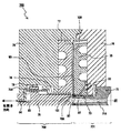
実施例1の射出成形機200は、図2(a)に示すように、主に固定金型201と、可動金型202と、固定金型201の型締め方向側の端面を支持する固定プラテン102と、可動金型202の型開き方向側の端面を支持する固定プラテン104と、固定金型201を支持するとともに軸AXに沿った可動金型202及び可動プラテン104の移動を支持する支持部203とで構成されている。可動金型202と固定金型201は、軸AXと同軸状に対向して配置されており、それらの間にはキャビティ100が画成される。図2(a)では、軸AXを可動金型202の中心に設けられているスタンパ保持部25の中心軸として表してある。また、図2(a)中の矢印に示すように、可動金型202が軸AXに沿って固定金型201から離れる方向を型開き方向とし、その逆方向を型締め方向と呼ぶ。
【0020】
可動金型202は、図2(a)に示すように、突き出しピン29を軸AXと同軸状に収容したスタンパ保持部25と、スタンパ保持部25を軸AXと同軸状に収容した可動鏡面27と、可動鏡面27、スタンパ保持部25及び突き出しピン29を軸AXと同軸状に収容している可動金型本体28とで構成されている。可動金型202は、可動金型本体28の型開き方向側の端面を支持し且つ突き出しロッド105を軸AXと同軸状に収容した可動プラテン104に装着されている。そして、この例ではスタンパ90は可動鏡面27のキャビティ側の表面に固定されている。
【0021】
固定金型201は、図2(a)に示すように、キャビティ100を挟んでスタンパ保持部25と対向する位置に軸AXと同軸状に配置されたスプールブッシュ21と、スプールブッシュ21を軸AXと同軸状に収容した固定ブッシュ22と、固定ブッシュ22を軸AXと同軸状に収容した固定鏡面23と、固定鏡面23及びスプールブッシュ21を軸AXと同軸状に収容している固定金型本体24とで構成されている。固定金型201は、固定金型本体24の型締め方向側の端面を支持し且つノズル103を軸AXと同軸状に収容した固定プラテン102に装着されている。
【0022】
スタンパ保持部25は、図2(b)に示すように、円筒状の部材であり、軸AXと同軸状に且つ軸AXに沿って延在する穴25Bを有し、その穴25B内部には突き出しピン29が軸AXと同軸状に収容されている。スタンパ保持部25の型締め方向側の端部はキャビティ100内に突出してフランジ部25Aを画成しており、このフランジ部25Aと可動鏡面27との間に、スタンパ90の内周部が挟持されている。スタンパ保持部25の外周壁近傍内部には、ガス通路37が形成されており、ガス通路37は可動鏡面27内部に形成されたガス通路34と連通されている。高圧エアは、図2(b)に示すように、ガス通路34及びガス通路37を通じて成形基板とスタンパ90との間に送り込まれ、成形基板をスタンパ90から剥離する。また、スタンパ保持部25は、スタンパ保持部25の型開き方向側の端面と接している可動金型本体28の表面に形成された吸引溝33を介して可動金型本体28に真空吸着により固定されている。スタンパ保持部25は可動金型202とともに、軸AXに沿って固定金型201に対して移動可能であり、このスタンパ保持部25の移動によりキャビティ100の開閉が行われる。
【0023】
固定ブッシュ22は、固定鏡面23内に軸AXと同軸状に収容された円筒状の部材であり、キャビティ100を挟んでスタンパ保持部25と対向する位置に配置されている。固定ブッシュ22の内径はスタンパ保持部25のフランジ部25Aの外径よりわずかに大きく、固定ブッシュ92とスタンパ保持部25のフランジ部25Aが互いに嵌合することにより、キャビティ100がゲートシールされ、基板の内周穴が成形される。
【0024】
スプールブッシュ21は、図2(a)に示すように、円筒状の部材であり、スプールブッシュ21内部には、軸AXと同軸状に且つ軸AXに沿って延在する通路21aが形成されている。通路21Aはキャビティ100に向かって内径が広くなるテーパー状の断面を有す。通路21Aを介して溶融樹脂がキャビティ100内に射出される。また、スプールブッシュ21は、ノズル103のタッチ圧力P1(図3参照)と、固定金型本体24及びスプールブッシュ21の間に配置された戻しバネ30の弾性力により、軸AXに沿って固定金型本体24内で移動可能である。図2(a)に示すように、スプールブッシュ21が軸AXに沿ってスムーズに移動するように、固定金型本体24とスプールブッシュ21の間には、ボールリティーナ31が埋め込まれている。
【0025】
スタンパ90は、Ni等で形成され、スタンパ90表面にはサブミクロンオーダーのプリピットやプリグルーブが形成されている。スタンパ90の内周部は、図2(b)に示すように、スタンパ保持部25のフランジ部25Aで保持されているだけでなく、可動鏡面27の内周壁とスタンパ保持部25の外周壁との間に画成されたスリット35と、それと連通する可動鏡面27内に形成された吸引路36を介して可動鏡面27に真空吸着されている。スタンパ90外周部は図示しないエアバキューム溝から真空吸着等によって可動鏡面27に固定されている。
【0026】
この例では、熱可塑性樹脂にポリカーボネートを用いた。キャビティ100内に射出する樹脂温度は340℃、金型温度は120℃となるようにそれぞれ温度制御した。樹脂材料にはポリカーボネート以外に、ポリメチルメタクリレート、非晶質ポリオレフィン、ポリエーテルイミド等を用いても良い。
【0027】
次に、上記構成の射出成形機200の動作を、図3〜図6を用いて説明する。キャビティ100内に溶融樹脂52を充填した時の様子を図3に示す。溶融樹脂52の充填時には、図3(b)に示すように、可動金型202を軸AXに沿って型開き方向に移動させて、キャビティ100のゲート101を開けた。スプールブッシュ21内の通路21Aから溶融樹脂が射出されると、溶融樹脂はゲート101を通ってキャビティ100内に流れ込む。キャビティ100の開き量Tは任意であるが、この例ではT=0.5mmとした。ここで、キャビティ100の開き量Tは、図3(a)に示すように、可動金型本体28のガイドリング108と固定金型本体24のガイドリング107の隙間の幅で表す。溶融樹脂充填時には、開き量がT=0.5mmで一定あるように型締め圧P2を調節した。この時、ゲート101の開き量t1は0.4mmであった。また、図3(a)から分かるように、溶融樹脂52が光ディスク用基板の外周端部を成形するための部材である外周リング38にまで到達しないように充填量を調節した。
【0028】
溶融樹脂52を充填完了後、図4に示すように、可動金型202を型締め方向に移動させて、キャビティ100内の溶融樹脂52を型締め圧P4で圧縮した。ゲート101の開き量t2が0.05mmとなるまで20トンの型締め圧P4で圧縮した。この時、キャビティ内の圧力を緩和するために、ノズル103のタッチ圧力P3を下げ、スプールブッシュ21を型締め方向に移動させることにより、スタンパ保持部25とスプールブッシュ21の間の空間を広げた。
【0029】
さらに可動金型202を型締め方向に移動させて溶融樹脂52を圧縮し、図5に示すように、スタンパ保持部25のフランジ部25Aを固定ブッシュ22内にわずかに挿入させることによりキャビティ100のゲートシールを行った。この際、挿入幅t3は0.1mmとした。図4に示した溶融樹脂の圧縮状態から図5のゲートシールされるまでの工程間、型締め圧P5を20トンから2トンまで下げながら溶融樹脂を型締めした。この例では、樹脂充填後からゲートシールまでを0.1秒で行った。そして、ゲートシール後、冷却しながら型締め圧を10トンとして型締めを行った。
【0030】
冷却後、図6(a)に示すように、可動金型202を型開き方向に移動させて、成形基板60と、スプールブッシュ21内で固化した樹脂61を、固定鏡面23及びスプールブッシュ21から剥離した。その後、図6(c)に示すように、スタンパ90とスタンパ保持部25のフランジ部25Aとの間に画成された10μm程度のクリアランス32を介して高圧エアを成形基板60に噴射して、成形基板60をスタンパ90から離型した。また、スプールブッシュ21内で固化した樹脂61は、スタンパ保持部25の内部に収容された突き出しピン29により型締め方向に押し出されて、スタンパ保持部25のフランジ部25Aから剥離した。
【0031】
上述の光ディスク用基板の成形金型及び成形方法を用いると、偏芯が3〜5μm(P−P)の基板を繰り返し成形することが出来た。また、上記の成形方法及び成形金型では、基板の内周穴を成形するスタンパ保持部25のフランジ部25Aにより、スタンパ90の内周部が保持されているので、図1に示すように基板の内周穴11近傍の領域13に全く凹凸の無い完全に平滑な面を有する基板が得られた。この基板には、従来の基板に存在していたスタンパのツメ跡が無い点に注目されたい。
【0032】
【実施例2】
実施例2の射出成形機700は、図7に示すように、主に固定金型701と、可動金型702と、固定金型701の型締め方向側の端面を支持する図示しない固定プラテンと、可動金型702の型開き方向側の端面を支持する図示しない固定プラテンと、固定金型701を支持するとともに軸AXに沿った可動金型702及び可動プラテンの移動を支持する図示しない支持部とで構成されている。可動金型702と固定金型701は、軸AXと同軸状に対向して配置されており、それらの間にはキャビティ100が画成されている。図7において、軸AXをスタンパ保持部70の中心軸として表した。
【0033】
可動金型702は、図7に示すように、軸AXと同軸状に配置されている円柱状のピストン75と、ピストン75を軸AXと同軸状に収容したエジェクター76と、エジェクター76を軸AXと同軸状に収容した可動鏡面77と、可動鏡面77、エジェクター76及びピストン75を軸AXと同軸状に収容している可動金型本体78とで構成されている。
【0034】
固定金型701は、図7に示すように、キャビティ100を挟んで軸AXと同軸状にピストン75と対向する位置に配置されたスプールブッシュ71と、スプールブッシュ71を軸AXと同軸状に収容したスタンパ保持部70と、スタンパ保持部70を軸AXと同軸状に収容した固定鏡面73と、固定鏡面73、スタンパ保持部70及びスプールブッシュ71を軸AXと同軸状に収容している固定金型本体74とで構成されている。そして、この例では、図7に示すように、スタンパ90は固定鏡面73のキャビティ100側の表面に固定されている。
【0035】
スタンパ保持部70は、図7に示すように、円筒状の部材であり、スプールブッシュ71と固定鏡面73の間の領域に軸AXと同軸状に保持されている。スタンパ保持部70の型開き方向側の端部はキャビティ100内に突出してフランジ部70Aを画成しており、このフランジ部70Aと固定鏡面73との間にスタンパ90の内周部が挟持されている。また、スタンパ保持部70の外周壁近傍内部には、ガス通路80が形成されており、高圧エアはガス通路80を通じて成形基板とスタンパ90との間に送り込まれ、成形基板をスタンパ90から剥離する。
【0036】
スプールブッシュ71は、図7に示すように、円筒状の部材であり、スプールブッシュ71内部には、軸AXと同軸状に且つ軸AXに沿って延在する通路71Aが形成されている。通路71Aは軸AXに沿ってキャビティ100に向かって内径が広くなるテーパー状の断面を有す。通路71Aを介して溶融樹脂がキャビティ100内に射出される。
【0037】
エジェクター76は、図7に示すように、可動鏡面77内に軸AXと同軸状に収容された円筒状の部材であり、キャビティ100を挟んでスタンパ保持部70と対向する位置に配置されている。エジェクター76は後述する突き出しピン84により軸AXに沿って可動鏡面77及び可動金型本体78に対して移動可能であり、エジェクター76の移動によりキャビティ100の開閉が行われる。エジェクター76の内径はスタンパ保持部70のフランジ部70Aの外径よりわずかに大きく、エジェクター76とスタンパ保持部70のフランジ部70Aが互いに嵌合することにより、キャビティ100がゲートシールされて基板の内周穴が成形される。
【0038】
ピストン75は、図7に示すように、円柱状の部材である。ピストン75の型開き方向の端部付近に形成された大径部75Aには断面が鉤状のシリンダボア83が形成されており、そのシリンダボア83には、エジェクター76に連結されエジェクター76を軸AX方向に移動させるための鉤状の突き出しピン84が軸AXと同軸状に収容されている。また、ゲートシール時にスプールブッシュ71内部の応力を緩和するために、ピストン75は軸AXに沿って型開き方向に移動(後退)可能である。ピストン75は、ピストン75の型開き方向側に軸AXと同軸状に設置されている図示しない駆動ピストンにより駆動される。また、図7に示すように、ピストン75が軸AXに沿ってスムーズに移動するように、可動金型78とピストン75の間にはボールリティーナ79が埋め込まれている。
【0039】
スタンパ90は、Ni等で形成され、その表面には、サブミクロンオーダーのプリピットやプリグルーブが形成されている。スタンパ90の内周部は、図7に示すように、スタンパ保持部70のフランジ部70Aで保持されているだけでなく、固定鏡面73の内周壁及びスタンパ保持部70の外周壁との間に画成されたスリット82と、それと連通する固定鏡面73内に形成された吸引路81を介して固定鏡面73に真空吸着されている。スタンパ90外周部は図示しないエアバキューム溝から真空吸着等によって固定鏡面73に固定されている。また、この例では、実施例1と同様に、熱可塑性樹脂にポリカーボネートを用いて射出成形した。
【0040】
次に、上記構成の射出成形機700の動作を図7及び8を用いて説明する。溶融樹脂の充填時には、図7に示すように、エジェクター76を軸AXに沿って型開き方向に移動させてキャビティ100のゲート101を開いた。そして、スプールブッシュ71内部の通路71Aを介してキャビティ100内に溶融樹脂を射出した。溶融樹脂充填後、図8に示すように、エジェクター76を軸AXに沿って型締め方向に移動させて、スタンパ保持部70のフランジ部70Aが、エジェクター76の内部に少しだけ挿入させることによってゲートシールした。この時、スプールブッシュ71内の応力緩和のために、ピストン75は軸AXに沿って型開き方向に移動して、スプールブッシュ71とピストン75の間の空間を広げた。ゲートシール後、冷却しながら、可動金型702で型締めした。冷却後、可動金型702を軸AXに沿って型開き方向に移動させて、成形基板をスタンパ90から剥離した。その後、エジェクター76をさらに型締め方向に移動させて、成形基板を型締め方向に押し出して可動鏡面77から離型した。
【0041】
【発明の効果】
本発明の成形金型及び成形方法に従えば、一対の金型にそれぞれ設けられ固定された凸部及び凹部を互いに嵌合させてキャビティのゲートシールを行い、光ディスク用基板の内周穴を成形するので、非常に偏芯が少なく、内周穴に対して同軸性が極めて高い光ディスク用基板を得ることができる。また、本発明の成形金型は独立可動部品が少ないため構造が簡単であり、低コストで製造することがという利点もある。
【0042】
また、本発明の成形金型及び成形方法に従えば、光ディスク用基板の内周穴を成形するために一方の金型に設けられた凸部でスタンパの内周部を取り付けているので、光ディスク用基板の内周部から外周部に渡る全ての領域にスタンパのパターンを転写することが出来る。これにより、光ディスク用基板の内周部近傍の表面に不要な凹部を生じさせずに、平滑な光ディスク用基板を作製することが出来る。得られた基板は情報記録領域を従来の基板に比べて拡大させることができるので、記憶容量が増大された光ディスクを提供することが出来る。
【図面の簡単な説明】
【図1】本発明の成形方法で作製された光ディスク用基板の概略断面図である。
【図2】実施例1の射出成形機の概略断面図であり、(a)は射出成形機の全体断面図であり、(b)は図2(a)中の領域Aの拡大図である。
【図3】実施例1で用いた成形金型のキャビティ内に溶融樹脂を充填させた時の射出成形機の概略断面図であり、(a)は射出成形機の全体断面図であり、(b)は図3(a)中の領域Bの拡大図である。
【図4】実施例1で用いた成形金型のキャビティ内に溶融樹脂を圧縮する時の射出成形機の概略断面図であり、(a)は射出成形機の全体断面図であり、(b)は図4(a)中の領域Cの拡大図である。
【図5】実施例1で用いた成形金型のゲートシール時の射出成形機の概略断面図であり、(a)は射出成形機の全体断面図であり、(b)は図5(a)中の領域Dの拡大図である。
【図6】実施例1で用いた成形金型の成形基板を離型する時の射出成形機の概略断面図であり、(a)は射出成形機の全体断面図であり、(b)は図6(a)中の領域Eの拡大図であり、(c)は図6(b)中の領域Fの拡大図である。
【図7】実施例2の射出成形機の概略断面図であり、溶融樹脂を充填した時の概略断面図である。
【図8】実施例2の射出成形機の概略断面図であり、ゲートシール時の概略断面図である。
【図9】従来の射出成形機の概略断面図であり、(a)は射出成形機の全体断面図であり、(b)は図9(a)中の領域Hの拡大図である。
【符号の説明】
21,71,91 スプールブッシュ
22,92 固定ブッシュ
23,73,93 固定鏡面
24,74,94 固定金型本体
25,70 スタンパ保持部
27,77,97 可動鏡面
28,78,98 可動金型本体
76,96 エジェクター
90 スタンパ
95 カットパンチ
99 スタンパ押さえ
100 キャビティ
101 ゲート
201,701,901 固定金型
202,702,902 可動金型[0001]
TECHNICAL FIELD OF THE INVENTION
The present invention relates to a molding die for an information recording disk substrate, a molding method, and a substrate produced by the molding method, and more particularly to a molding die, a molding method, and a molding method for a resin substrate for an optical disk. Related to the substrate.
[0002]
[Prior art]
In recent years, not only information for computers but also information such as music, still images, and moving images has been digitized, and the amount of information to be handled has been extremely increased. Accordingly, an optical disk for storing such information is required to have a large capacity. In order to meet this demand, optical disks such as DVD-RAM and DVD-RW having a capacity seven times or more that of conventional CD-R and CD-RW have already been commercialized.
[0003]
An optical disk is manufactured by sequentially laminating a recording layer, a reflective layer, a protective layer, and the like on a resin substrate. The resin substrate of the optical disk is formed by injecting a molten thermoplastic resin into a cavity defined by a pair of dies.
[0004]
An injection molding method for an optical disk substrate will be described with reference to FIG. As shown in FIG. 9A, the
[0005]
As shown in FIG. 9A, a
[0006]
The operation of the
[0007]
[Problems to be solved by the invention]
By the way, also with respect to optical discs, research for minimizing the light spot size using a blue laser and a high NA lens to perform high-density recording has been actively conducted. Since the track pitch of the optical disk is further narrowed with such high-density recording, it is necessary to perform tracking for causing the light beam to follow a desired track with higher precision. Factors that hinder tracking include eccentricity of the optical disc substrate.
[0008]
In the conventional injection molding method, there is a limit in reducing the eccentricity of the disk substrate due to accumulation of various fluctuation factors. As described above, the inner peripheral hole of the optical disc substrate is moved by moving the cut punch 95 along the axis AX in the movable mold
[0009]
Further, as shown in FIG. 9B, the inner peripheral portion of the
[0010]
Further, when the molten resin flows into the
[0011]
SUMMARY OF THE INVENTION The present invention has been made to solve the above-mentioned problems of the prior art, and a first object of the present invention is to provide a molding die and a molding method for molding an optical disk substrate without eccentricity. A second object of the present invention is to provide a molding method for producing an optical disc substrate in which the surface near the inner periphery is a smooth surface without generating unnecessary concave portions on the surface near the inner periphery of the optical disc substrate. It is to provide a mold and a molding method.
[0012]
[Means for Solving the Problems]
According to a first aspect of the present invention, there is provided a mold for molding an information recording disk substrate having an inner peripheral hole, wherein a pair of molds defining a cavity into which a molten resin is injected; A mold provided with a protrusion fixedly provided on one side of the mold and a recess provided on the other side of the mold and defining the inner peripheral hole by fitting with the protrusion. Is provided.
[0013]
In the molding die of the present invention, the inner peripheral surface of the substrate is formed using the
[0014]
Further, in the molding die of the present invention, as shown in FIG. 2, the inner peripheral portion of the
[0015]
According to a second aspect of the present invention, there is provided a method for molding an information recording disk substrate by an injection molding method, comprising: a convex portion fixed to a central portion of a first mold; A step of injecting a molten resin into a cavity defined by a first mold and a second mold each having a concave portion provided at the center of the mold, and applying the molten resin to the first mold and the second mold. A step of compressing the molten resin with a mold and a step of cooling and solidifying the molten resin, wherein the convex portion and the concave portion are fitted to each other in the compression step, whereby an inner peripheral hole of the substrate is defined. A method is provided.
[0016]
The molding method according to the second embodiment of the present invention will be described with reference to the molding die shown in FIG. 2 as an example. First, a molten resin is injected into the
[0017]
According to a third aspect of the present invention, in an information recording disk substrate having an inner peripheral hole and formed by transferring a pattern formed on a stamper, the information recording disk substrate is provided between an inner peripheral portion and an outer peripheral portion of the substrate. It has an information recording area, the area between the inner peripheral part and the information recording area is a flat surface without unevenness, and the entire area from the inner peripheral part to the outer peripheral part is transferred by the pattern of the stamper. A substrate characterized by being formed is provided.
[0018]
As shown in FIG. 1, the substrate for an information recording disk according to the present invention is a
[0019]
BEST MODE FOR CARRYING OUT THE INVENTION
Embodiment 1
As shown in FIG. 2A, the
[0020]
As shown in FIG. 2A, the
[0021]
As shown in FIG. 2A, the
[0022]
As shown in FIG. 2B, the
[0023]
The fixed
[0024]
As shown in FIG. 2A, the
[0025]
The
[0026]
In this example, polycarbonate was used as the thermoplastic resin. The temperature of the resin injected into the
[0027]
Next, the operation of the
[0028]
After the completion of the filling of the
[0029]
Further, the
[0030]
After the cooling, as shown in FIG. 6A, the
[0031]
By using the above-described mold and method for molding an optical disk substrate, a substrate having an eccentricity of 3 to 5 μm (PP) could be repeatedly molded. Further, in the above-described molding method and molding die, since the inner peripheral portion of the
[0032]
Embodiment 2
As shown in FIG. 7, the
[0033]
As shown in FIG. 7, the
[0034]
As shown in FIG. 7, the fixed
[0035]
As shown in FIG. 7, the
[0036]
As shown in FIG. 7, the
[0037]
As shown in FIG. 7, the
[0038]
The
[0039]
The
[0040]
Next, the operation of the
[0041]
【The invention's effect】
According to the molding die and the molding method of the present invention, the convex portion and the concave portion provided respectively in the pair of molds are fitted to each other to perform gate sealing of the cavity and form the inner peripheral hole of the optical disc substrate. Therefore, it is possible to obtain an optical disc substrate with very little eccentricity and extremely high coaxiality with the inner peripheral hole. In addition, since the molding die of the present invention has a small number of independently movable parts, the structure is simple and there is an advantage that it can be manufactured at low cost.
[0042]
According to the molding die and the molding method of the present invention, the inner peripheral portion of the stamper is attached to the convex portion provided on one of the molds for molding the inner peripheral hole of the optical disk substrate. The pattern of the stamper can be transferred to all regions from the inner periphery to the outer periphery of the substrate. This makes it possible to manufacture a smooth optical disc substrate without generating unnecessary concave portions on the surface near the inner peripheral portion of the optical disc substrate. Since the obtained substrate can enlarge the information recording area as compared with the conventional substrate, it is possible to provide an optical disk having an increased storage capacity.
[Brief description of the drawings]
FIG. 1 is a schematic sectional view of an optical disk substrate manufactured by a molding method of the present invention.
FIGS. 2A and 2B are schematic cross-sectional views of the injection molding machine of Example 1, wherein FIG. 2A is an overall cross-sectional view of the injection molding machine, and FIG. 2B is an enlarged view of a region A in FIG. .
FIG. 3 is a schematic cross-sectional view of an injection molding machine when a molten resin is filled in a cavity of a molding die used in Example 1, (a) is an overall cross-sectional view of the injection molding machine, FIG. 3B is an enlarged view of a region B in FIG.
FIG. 4 is a schematic sectional view of an injection molding machine when compressing a molten resin into a cavity of a molding die used in Example 1, (a) is an overall sectional view of the injection molding machine, and (b) is 4) is an enlarged view of a region C in FIG.
FIG. 5 is a schematic sectional view of an injection molding machine at the time of gate sealing of a molding die used in Example 1, (a) is an overall sectional view of the injection molding machine, and (b) is FIG. FIG.
FIG. 6 is a schematic sectional view of an injection molding machine when releasing a molding substrate of a molding die used in Example 1, (a) is an overall sectional view of the injection molding machine, and (b) is It is an enlarged view of the area | region E in FIG.6 (a), and (c) is an enlarged view of the area | region F in FIG.6 (b).
FIG. 7 is a schematic sectional view of the injection molding machine of Example 2, which is a schematic sectional view when a molten resin is filled.
FIG. 8 is a schematic cross-sectional view of the injection molding machine of Embodiment 2, and is a schematic cross-sectional view at the time of gate sealing.
9 is a schematic sectional view of a conventional injection molding machine, (a) is an overall sectional view of the injection molding machine, and (b) is an enlarged view of a region H in FIG. 9 (a).
[Explanation of symbols]
21, 71, 91 Spool bush
22, 92 Fixed bush
23, 73, 93 Fixed mirror surface
24, 74, 94 Fixed mold body
25, 70 Stamper holder
27, 77, 97 Movable mirror surface
28,78,98 Movable mold body
76,96 ejector
90 stamper
95 Cut Punch
99 Stamper Holder
100 cavities
101 gate
201,701,901 Fixed mold
202,702,902 Movable mold
Claims (9)
溶融樹脂が射出されるキャビティを画成する一対の金型と、
上記金型の一方に固定して設けられた凸部と、
上記金型の他方に設けられ、上記凸部と嵌合することによって上記内周穴を画成する凹部とを備えた成形用金型。A mold for molding an information recording disk substrate having an inner peripheral hole,
A pair of molds defining a cavity into which the molten resin is injected,
A convex portion fixedly provided on one of the molds,
A molding die provided on the other side of the die, the concave portion defining the inner peripheral hole by fitting with the convex portion.
第一金型の中央部に固定された凸部及び該凸部と嵌合する第二金型の中央部に設けられた凹部をそれぞれ有する第一金型及び第二金型により画成されたキャビティに溶融樹脂を射出する工程と、
上記溶融樹脂を上記第一金型及び第二金型で圧縮する工程と、
上記溶融樹脂を冷却して固化させる工程とを備え、
上記圧縮工程において上記凸部と上記凹部が嵌合することによって、上記基板の内周穴が画成される成形方法。A method of molding a substrate for an information recording disk by an injection molding method,
The first mold and the second mold have a convex portion fixed to the central portion of the first mold and a concave portion provided at the central portion of the second mold to be fitted with the convex portion, respectively. Injecting molten resin into the cavity;
A step of compressing the molten resin with the first mold and the second mold,
Cooling and solidifying the molten resin,
A molding method in which an inner peripheral hole of the substrate is defined by fitting the convex portion and the concave portion in the compression step.
基板の内周部から外周部の間に情報記録領域を有し、内周部から情報記録領域の間の領域が凹凸のない平坦面であり、上記内周部から外周部に渡る全ての領域が上記スタンパのパターンが転写されることによって形成されていることを特徴とする基板。An information recording disk substrate having an inner peripheral hole and formed by transferring a pattern formed on a stamper,
The substrate has an information recording area between the inner peripheral part and the outer peripheral part, and the area between the inner peripheral part and the information recording area is a flat surface without unevenness, and all the areas extending from the inner peripheral part to the outer peripheral part Is formed by transferring the pattern of the stamper.
Priority Applications (1)
| Application Number | Priority Date | Filing Date | Title |
|---|---|---|---|
| JP2002163669A JP2004009392A (en) | 2002-06-05 | 2002-06-05 | Mold for molding substrate for information recording disk, molding method therefor and substrate for information recording disk |
Applications Claiming Priority (1)
| Application Number | Priority Date | Filing Date | Title |
|---|---|---|---|
| JP2002163669A JP2004009392A (en) | 2002-06-05 | 2002-06-05 | Mold for molding substrate for information recording disk, molding method therefor and substrate for information recording disk |
Publications (2)
| Publication Number | Publication Date |
|---|---|
| JP2004009392A true JP2004009392A (en) | 2004-01-15 |
| JP2004009392A5 JP2004009392A5 (en) | 2005-10-06 |
Family
ID=30432028
Family Applications (1)
| Application Number | Title | Priority Date | Filing Date |
|---|---|---|---|
| JP2002163669A Pending JP2004009392A (en) | 2002-06-05 | 2002-06-05 | Mold for molding substrate for information recording disk, molding method therefor and substrate for information recording disk |
Country Status (1)
| Country | Link |
|---|---|
| JP (1) | JP2004009392A (en) |
-
2002
- 2002-06-05 JP JP2002163669A patent/JP2004009392A/en active Pending
Similar Documents
| Publication | Publication Date | Title |
|---|---|---|
| JP4593572B2 (en) | Injection molding apparatus, injection molding method and injection mold | |
| US5330693A (en) | Process and apparatus for injection-molding product having minute surface pattern and central hole | |
| US7396575B2 (en) | Molding die apparatus, method for disc substrate, and disc-shaped recording medium | |
| JP2004009392A (en) | Mold for molding substrate for information recording disk, molding method therefor and substrate for information recording disk | |
| JP2004118952A (en) | Intermediate for optical recording medium, molding metal mold, molding apparatus, and manufacturing method of optical recording medium | |
| JP3401795B2 (en) | Manufacturing method of disk substrate | |
| JPWO2004045822A1 (en) | Mold for molding, molding method, disk substrate and molding machine | |
| JP2007237407A (en) | Disk substrate molding method and blue lay disk | |
| KR100373474B1 (en) | Disk, Apparatus and Method for Manufacturing the Same | |
| JPH05307769A (en) | Optical disk substrate, apparatus and method for producing optical disk substrate | |
| JP4093686B2 (en) | Disc substrate molding die and molding apparatus | |
| JP3383387B2 (en) | Optical disc substrate and mold for molding this optical disc substrate | |
| JPH0751300B2 (en) | Molding method for preformatted optical disk substrate and mold used therefor | |
| JP3759174B2 (en) | Mold equipment for disk substrate molding | |
| JP2003291178A (en) | Mold device for molding | |
| JP3077411B2 (en) | Resin molding method and resin molding die for thin substrate | |
| JPH08287461A (en) | Metal mold for molding magnetic disk substrate and its molding method | |
| JPH0929789A (en) | Mold apparatus for molding disc board | |
| JPH08207083A (en) | Molding of optical disk and molding die | |
| JP3185830B2 (en) | Mold for recording disk molding | |
| JP2002074756A (en) | Optical disk, method for manufacturing the same and molding die for disk molded body | |
| JPH0939040A (en) | Disk substrate molding die device | |
| JP2005028782A (en) | Method for producing resin substrate and injection molding machine for the substrate | |
| JP2001225360A (en) | Method and apparatus for molding disk substrate | |
| JP2000317995A (en) | Apparatus and method for molding disk |
Legal Events
| Date | Code | Title | Description |
|---|---|---|---|
| A521 | Request for written amendment filed |
Free format text: JAPANESE INTERMEDIATE CODE: A523 Effective date: 20050524 |
|
| A621 | Written request for application examination |
Free format text: JAPANESE INTERMEDIATE CODE: A621 Effective date: 20050524 |
|
| A977 | Report on retrieval |
Free format text: JAPANESE INTERMEDIATE CODE: A971007 Effective date: 20061113 |
|
| A131 | Notification of reasons for refusal |
Free format text: JAPANESE INTERMEDIATE CODE: A131 Effective date: 20061121 |
|
| A02 | Decision of refusal |
Free format text: JAPANESE INTERMEDIATE CODE: A02 Effective date: 20070320 |