JP2001278159A5 - - Google Patents
Download PDFInfo
- Publication number
- JP2001278159A5 JP2001278159A5 JP2000096804A JP2000096804A JP2001278159A5 JP 2001278159 A5 JP2001278159 A5 JP 2001278159A5 JP 2000096804 A JP2000096804 A JP 2000096804A JP 2000096804 A JP2000096804 A JP 2000096804A JP 2001278159 A5 JP2001278159 A5 JP 2001278159A5
- Authority
- JP
- Japan
- Prior art keywords
- vehicle body
- tank
- cylinder head
- pipe
- hose
- Prior art date
- Legal status (The legal status is an assumption and is not a legal conclusion. Google has not performed a legal analysis and makes no representation as to the accuracy of the status listed.)
- Granted
Links
Images


Description
【0002】
【従来の技術】
特許第2951338号には、角断面パイプによりヘッドパイプから後方へ延出するメインフレームと、斜め下方へ延出するダウンフレームを形成することが示され、かつこのダウンフレームをスエージング加工で形成することが示されている。
[0002]
[Prior Art]
Japanese Patent No. 2951338 shows that a square cross section pipe forms a main frame extending backward from a head pipe and a down frame extending obliquely downward, and this down frame is formed by swaging. It is shown.
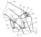
ラジエタ22は左右一対でダウンチューブ5の両側へ支持され(図5参照)、その上部タンク30とシリンダヘッドカバー28の間に復水側ホース31が配管される。また下部タンク32からは送水側ホース33が延出しクランクケース29側と接続している。
落とし込み部41は4サイクルエンジン2の上方へ突出するシリンダヘッド27及びシリンダヘッドカバー28の後方かつ後部クロス部材43の前方に形成される落とし込み用の空間57a内へ突出して配置され、その車体前後方向ではシリンダヘッドカバー28と重なる高さであり、かつ側面視では気化器24の上部と重なる位置になっている。
The drop-in
図4に明らかなように、落とし込み部41の下方に設けられる燃料コック42の位置はその下端が側面視でメインフレーム4の下縁よりも多少下方へ出るように配置され、かつ落とし込み部41はメインフレーム4と重なる位置になっている。また図3に明らかなように、落とし込み部41は気化器24と車幅方向へ併設されている。
As apparent from FIG. 4, the position of the
次に、ダウンチューブ5近傍における部品のレイアウトにつき説明する。図5はラジエタ22のレイアウト等についてダウンチューブ5及びその近傍部品を車体前方側から示す図であり、ラジエタ22は左右に対で設けられ、それぞれの上部タンク30は復水側ホース31で連結され、ジョイント管31aでシリンダヘッドカバー28側のウォータージャケット出口へ接続されている。
Next, the layout of parts in the vicinity of the down tube 5 will be described. Figure 5 is a view showing the vehicle body front side of the down tube 5 and the vicinity part thereof layout, etc. of the
また、各下部タンク32から出た送水側ホース33は車体中央側へ延び、ダウンチューブ5のテーパー状部62b後方を左右方向へ横切るジョイントホース34へ接続し、このジョイントホース34の車体右側部分に設けられたジョイント部34aでクランクケースの右側に設けられているウォーターポンプ49へ接続している。なお、排気管23もテーパー状部62bの後方を通って斜め下がりに車体右側へ出てから、右側のラジエタ22の下方を通って後方へ延びている。
Also, water-
またこれらの後方かつ車体中心の近傍にリヤクッション19が位置し、リヤクッション19に並設されたそのリザーブタンク19aの前方へ重なるように燃料コック42が位置している。さらに燃料コック42及びリザーブタンク19aの各下方を通って排気管23が配設されている。排気管23の前部はシリンダヘッド27(図1参照)の前部から斜め右側へ出てから再び車体内側へ曲がり直して(図5参照)、その後右側のピボットプレート6の内側かつ前記したように燃料コック42及びリザーブタンク19aの各下方を通り、その後やや車体右側かつ上方へ曲がりながら後方へ延びている。なお、気化器24へ接続するコンチューブ(本図では省略)と排気管23はそれぞれリヤクッション19の左右両側へ分かれて配設される。
A
後部クロス部材43はアルミ合金等を鋳造や鍛造等により得られた中空の部材であり、この上面44は燃料タンク20の後端部45を乗せて支持する支持部をなしている。また、中央部には後方へ二股状に突出するクッションブラケット46が一体に形成され、ここにリヤクッション19の上端47が回動自在に支持されている(図4参照)。このクッションブラケット46は、若干車体中心Cよりオフセットされているが、このオフセットが最小となる位置に設けられる。また、クッションブラケット46の上部にはシートレール8の取付部が形成されている。
The
後部クロス部材43の下方かつ左右のピボットプレート6及び下方のピボット軸15で挟まれた空間56(図6)は極めて大きな連続する空間をなし、ここに図6で前記したようにリヤクッション19及び排気管23、コンチューブ36が配設されている。また、後部クロス部材43より前方の空間もテンションパイプ50より上方かつヘッドパイプ3より後方に連続する大きな燃料タンク収容空間57(図8)として形成され、その一部でエンジン2のシリンダヘッドカバー28より後方側がシリンダ後方の空間57aをなしている(図3)。
The space 56 (FIG. 6) sandwiched by the lower and
さらに、後面62のうち、後面上部62aをストレート部としたので、ここを接合面としてガセット51を溶接する場合における溶接作業が容易である。
Furthermore, since the rear
Priority Applications (5)
| Application Number | Priority Date | Filing Date | Title |
|---|---|---|---|
| JP2000096804A JP3766580B2 (en) | 2000-03-31 | 2000-03-31 | Manufacturing method of body frame for motorcycle |
| AT01107596T ATE328782T1 (en) | 2000-03-31 | 2001-03-27 | MOTORCYCLE FRAME |
| ES01107596T ES2260111T3 (en) | 2000-03-31 | 2001-03-27 | MOTORCYCLE FRAME. |
| EP01107596A EP1138588B1 (en) | 2000-03-31 | 2001-03-27 | A motorcycle frame |
| US09/820,839 US6695089B2 (en) | 2000-03-31 | 2001-03-30 | Motorcycle frame |
Applications Claiming Priority (1)
| Application Number | Priority Date | Filing Date | Title |
|---|---|---|---|
| JP2000096804A JP3766580B2 (en) | 2000-03-31 | 2000-03-31 | Manufacturing method of body frame for motorcycle |
Publications (3)
| Publication Number | Publication Date |
|---|---|
| JP2001278159A JP2001278159A (en) | 2001-10-10 |
| JP2001278159A5 true JP2001278159A5 (en) | 2005-06-09 |
| JP3766580B2 JP3766580B2 (en) | 2006-04-12 |
Family
ID=18611519
Family Applications (1)
| Application Number | Title | Priority Date | Filing Date |
|---|---|---|---|
| JP2000096804A Expired - Fee Related JP3766580B2 (en) | 2000-03-31 | 2000-03-31 | Manufacturing method of body frame for motorcycle |
Country Status (5)
| Country | Link |
|---|---|
| US (1) | US6695089B2 (en) |
| EP (1) | EP1138588B1 (en) |
| JP (1) | JP3766580B2 (en) |
| AT (1) | ATE328782T1 (en) |
| ES (1) | ES2260111T3 (en) |
Families Citing this family (52)
| Publication number | Priority date | Publication date | Assignee | Title |
|---|---|---|---|---|
| JP2001247073A (en) * | 2000-03-02 | 2001-09-11 | Honda Motor Co Ltd | Car body frame structure |
| JP4368596B2 (en) * | 2003-02-26 | 2009-11-18 | 本田技研工業株式会社 | Body structure of motorcycle |
| JP4233022B2 (en) * | 2003-02-27 | 2009-03-04 | 本田技研工業株式会社 | Motorcycle frame structure |
| US7438147B2 (en) | 2003-04-02 | 2008-10-21 | Yamaha Hatsudoki Kabushiki Kaisha | Transmission for off-road vehicle |
| US7147075B2 (en) * | 2003-04-02 | 2006-12-12 | Yamaha Hatsudoki Kabushiki Kaisha | Engine arrangement for off-road vehicle |
| US7506712B2 (en) | 2003-04-02 | 2009-03-24 | Yamaha Hatsudoki Kabushiki Kaisha | Off road vehicle with air intake system |
| US7650959B2 (en) | 2003-04-02 | 2010-01-26 | Yamaha Hatsudoki Kabushiki Kaisha | Frame arrangement for off-road vehicle |
| JP2007022097A (en) * | 2003-08-20 | 2007-02-01 | Yamaha Motor Co Ltd | Saddle-riding type vehicle |
| JP4163585B2 (en) * | 2003-09-30 | 2008-10-08 | 本田技研工業株式会社 | Motorcycle body structure |
| JP2005138820A (en) * | 2003-10-16 | 2005-06-02 | Yamaha Motor Co Ltd | Saddle ride type vehicle |
| JP2005280507A (en) * | 2004-03-30 | 2005-10-13 | Yamaha Motor Co Ltd | Engine support device of motorcycle |
| CA2502056C (en) * | 2004-03-31 | 2009-06-30 | Honda Motor Co., Ltd. | All terrain vehicle |
| JP2006015837A (en) * | 2004-06-30 | 2006-01-19 | Yamaha Motor Co Ltd | Motorcycle |
| US20060032686A1 (en) * | 2004-08-12 | 2006-02-16 | Norman Berg | Spindle for snowmobile suspension |
| JP2006056355A (en) * | 2004-08-19 | 2006-03-02 | Honda Motor Co Ltd | Exhaust structure in fuel cell vehicle |
| JP4731926B2 (en) * | 2005-01-31 | 2011-07-27 | 川崎重工業株式会社 | Motorcycle frame |
| US7637345B2 (en) * | 2004-12-24 | 2009-12-29 | Kawasaki Jukogyo Kabushiki Kaisha | Frame of motorcycle and engine bracket |
| US7497455B2 (en) | 2005-01-28 | 2009-03-03 | Michael Kamalian | Carbon fiber motorcycle frame |
| JP4516497B2 (en) * | 2005-03-02 | 2010-08-04 | 本田技研工業株式会社 | Motorcycle body frame |
| JP4684715B2 (en) * | 2005-04-01 | 2011-05-18 | 川崎重工業株式会社 | Vehicle shroud |
| JP4991159B2 (en) * | 2006-01-31 | 2012-08-01 | 本田技研工業株式会社 | Motorcycle body frame |
| JP4582035B2 (en) * | 2006-03-27 | 2010-11-17 | 株式会社デンソー | Motorcycle heat exchanger and method of manufacturing the same |
| JP2007308131A (en) * | 2006-04-20 | 2007-11-29 | Denso Corp | Heat exchanger for motorcycle |
| JP2008143511A (en) * | 2006-11-15 | 2008-06-26 | Yamaha Motor Co Ltd | Vehicle body frame and vehicle |
| JP2008222077A (en) * | 2007-03-13 | 2008-09-25 | Yamaha Motor Co Ltd | Body frame of motorcycle, assembling method for mounting engine on body frame, and motorcycle equipped with body frame |
| JP2008222010A (en) * | 2007-03-13 | 2008-09-25 | Yamaha Motor Co Ltd | Vehicle |
| JP2009090893A (en) * | 2007-10-10 | 2009-04-30 | Yamaha Motor Co Ltd | Saddle-riding type vehicle |
| JP2009132355A (en) * | 2007-10-30 | 2009-06-18 | Yamaha Motor Co Ltd | Radiator cover for straddle-riding type vehicle, and straddle-riding type vehicle provided with it |
| US7779951B1 (en) * | 2008-01-19 | 2010-08-24 | Victor Cabanas | Process for building the rear portion of a motorcycle |
| JP2009255627A (en) * | 2008-04-14 | 2009-11-05 | Yamaha Motor Co Ltd | Saddle-riding type vehicle |
| JP2009255626A (en) | 2008-04-14 | 2009-11-05 | Yamaha Motor Co Ltd | Motorcycle |
| US20100018793A1 (en) * | 2008-07-24 | 2010-01-28 | Arnold David W | Saddle-type vehicles having dual l-shaped radiators |
| JP3154637U (en) * | 2008-08-08 | 2009-10-22 | ヤマハ発動機株式会社 | Saddle riding type vehicle |
| US7980347B2 (en) * | 2008-10-21 | 2011-07-19 | Honda Motor Company, Ltd. | Motorcycles having frame with aperture passing flexible drive member and methods |
| JP5548499B2 (en) * | 2010-03-30 | 2014-07-16 | 本田技研工業株式会社 | Saddle riding |
| JP2011240774A (en) * | 2010-05-17 | 2011-12-01 | Suzuki Motor Corp | Vehicle body frame of motorcycle |
| JP5618856B2 (en) * | 2011-02-14 | 2014-11-05 | 本田技研工業株式会社 | Motorcycle body frame |
| JP5675413B2 (en) * | 2011-02-14 | 2015-02-25 | 本田技研工業株式会社 | Motorcycle body frame |
| JP5853618B2 (en) * | 2011-11-11 | 2016-02-09 | スズキ株式会社 | Frame structure of saddle riding type vehicle |
| JP5690706B2 (en) * | 2011-11-16 | 2015-03-25 | 本田技研工業株式会社 | Radiator structure of saddle riding type vehicle |
| JP5661026B2 (en) * | 2011-12-20 | 2015-01-28 | 本田技研工業株式会社 | Hollow welded frame structure |
| JP5969232B2 (en) * | 2012-03-22 | 2016-08-17 | 本田技研工業株式会社 | Radiator hose layout structure for saddle-ride type vehicles |
| FR2993212B1 (en) * | 2012-07-13 | 2015-11-27 | Rdmo | MOTORCYCLE WITH LIQUID COOLING ENGINE |
| JP6202516B2 (en) * | 2013-01-31 | 2017-09-27 | 本田技研工業株式会社 | Saddle riding |
| JP6140556B2 (en) * | 2013-07-10 | 2017-05-31 | 本田技研工業株式会社 | Motorcycle |
| JP6126954B2 (en) * | 2013-09-11 | 2017-05-10 | 本田技研工業株式会社 | Saddle riding vehicle |
| JP6158944B2 (en) * | 2013-11-07 | 2017-07-05 | 川崎重工業株式会社 | Body frame structure of saddle riding type vehicle |
| JP6223252B2 (en) * | 2014-03-27 | 2017-11-01 | 本田技研工業株式会社 | Body frame structure of motorcycle |
| JP2018086907A (en) * | 2016-11-28 | 2018-06-07 | ヤマハ発動機株式会社 | Saddle-riding type vehicle |
| JP6815348B2 (en) * | 2018-03-28 | 2021-01-20 | 本田技研工業株式会社 | How to make side stands and side stands for motorcycles |
| US11117637B2 (en) | 2018-07-25 | 2021-09-14 | Harley-Davidson Motor Company Group, LLC | Motorcycle frame |
| JP6749979B2 (en) * | 2018-09-27 | 2020-09-02 | 本田技研工業株式会社 | Saddle-type electric vehicle |
Family Cites Families (20)
| Publication number | Priority date | Publication date | Assignee | Title |
|---|---|---|---|---|
| GB498696A (en) * | 1936-08-04 | 1939-01-12 | Audi Ag | Improvements in frames for motor cycles and methods of producing same |
| JPS5950938A (en) * | 1982-09-14 | 1984-03-24 | Teruaki Yoshida | Manufacture of car body frame for automobile |
| JPS6094817A (en) * | 1983-10-31 | 1985-05-28 | Yamaha Motor Co Ltd | Radiator for autotricycle or the like |
| JPS6229481A (en) * | 1985-07-30 | 1987-02-07 | 本田技研工業株式会社 | Brake cooling structure of motorcycle |
| US4662645A (en) * | 1985-11-25 | 1987-05-05 | Wald Manufacturing Co., Inc. | Bicycle fork |
| US4809999A (en) * | 1986-03-04 | 1989-03-07 | Honda Giken Kogyo Kabushiki Kaisha | Tubular frame member |
| US4805716A (en) * | 1987-08-12 | 1989-02-21 | Honda Giken Kogyo Kabushiki Kaisha | Motorcycle body frame structure |
| JPH01226484A (en) * | 1988-03-08 | 1989-09-11 | Suzuki Motor Co Ltd | Frame member for motorcycle |
| JPH0274488A (en) * | 1988-09-12 | 1990-03-14 | Suzuki Motor Co Ltd | Car body frame for motorcycle |
| JP2951338B2 (en) | 1989-09-29 | 1999-09-20 | ヤマハ発動機株式会社 | Body frame structure of motorcycle |
| EP0447899B1 (en) * | 1990-03-09 | 1997-06-18 | Yamaha Hatsudoki Kabushiki Kaisha | Frame construction for a motorcycle type vehicle |
| US5261504A (en) * | 1990-03-09 | 1993-11-16 | Yamaha Hatsudoki Kabushiki Kaisha | Motorcycle frame construction |
| JP3561313B2 (en) * | 1995-02-07 | 2004-09-02 | 本田技研工業株式会社 | Oil cooling structure for motorcycles |
| JP3023657B2 (en) * | 1995-09-25 | 2000-03-21 | 本田技研工業株式会社 | Rear swing arm of motorcycle |
| JPH0995279A (en) * | 1995-09-29 | 1997-04-08 | Honda Motor Co Ltd | Car body frame for motorcycle |
| JP3594158B2 (en) * | 1996-08-30 | 2004-11-24 | 本田技研工業株式会社 | Body frame structure of motorcycle |
| CN1121329C (en) * | 1998-09-11 | 2003-09-17 | 本田技研工业株式会社 | Frame integrated fuel tank structure |
| JP4145426B2 (en) * | 1999-06-16 | 2008-09-03 | 本田技研工業株式会社 | Radiator structure of motorcycle |
| JP4280375B2 (en) * | 1999-09-05 | 2009-06-17 | 本田技研工業株式会社 | Motorcycle cooling device |
| JP3907375B2 (en) * | 2000-03-31 | 2007-04-18 | 本田技研工業株式会社 | Body frame for motorcycles |
-
2000
- 2000-03-31 JP JP2000096804A patent/JP3766580B2/en not_active Expired - Fee Related
-
2001
- 2001-03-27 AT AT01107596T patent/ATE328782T1/en active
- 2001-03-27 ES ES01107596T patent/ES2260111T3/en not_active Expired - Lifetime
- 2001-03-27 EP EP01107596A patent/EP1138588B1/en not_active Expired - Lifetime
- 2001-03-30 US US09/820,839 patent/US6695089B2/en not_active Expired - Fee Related
Similar Documents
| Publication | Publication Date | Title |
|---|---|---|
| JP2001278159A5 (en) | ||
| JP3766580B2 (en) | Manufacturing method of body frame for motorcycle | |
| US5704442A (en) | Frame structure for a motorcycle | |
| JP4364362B2 (en) | Motorcycle frame structure | |
| JP3907375B2 (en) | Body frame for motorcycles | |
| JP4785557B2 (en) | Exhaust structure of motorcycle | |
| JP3766579B2 (en) | Motorcycle fuel tank arrangement structure | |
| JP2001278152A5 (en) | ||
| JP2002037170A (en) | Car body structure of motorcycle | |
| JP4256370B2 (en) | Exhaust pipe arrangement structure for motorcycles | |
| JP4648132B2 (en) | Vaporizer arrangement structure in small vehicles | |
| JP4152998B2 (en) | Body frame for motorcycles | |
| JP2979015B2 (en) | Motorcycle | |
| JPH0441116B2 (en) | ||
| JPH0641270B2 (en) | Motorcycle frame | |
| JP3328843B2 (en) | Motorcycle frame | |
| JP3609233B2 (en) | Body frame structure of motorcycle | |
| JP2646356B2 (en) | Motorcycle frame structure | |
| JPS6130954Y2 (en) | ||
| JPH0413196B2 (en) | ||
| JPH062875Y2 (en) | Intake device for vehicle having pipe frame | |
| JP2008201418A (en) | Motorcycle | |
| JPH0579807B2 (en) | ||
| JPH0373732B2 (en) | ||
| JPH01156189A (en) | Motorcycle |