JP3766579B2 - Motorcycle fuel tank arrangement structure - Google Patents
Motorcycle fuel tank arrangement structure Download PDFInfo
- Publication number
- JP3766579B2 JP3766579B2 JP2000096803A JP2000096803A JP3766579B2 JP 3766579 B2 JP3766579 B2 JP 3766579B2 JP 2000096803 A JP2000096803 A JP 2000096803A JP 2000096803 A JP2000096803 A JP 2000096803A JP 3766579 B2 JP3766579 B2 JP 3766579B2
- Authority
- JP
- Japan
- Prior art keywords
- fuel tank
- drop
- vehicle body
- motorcycle
- engine
- Prior art date
- Legal status (The legal status is an assumption and is not a legal conclusion. Google has not performed a legal analysis and makes no representation as to the accuracy of the status listed.)
- Expired - Fee Related
Links
Images


Classifications
-
- B—PERFORMING OPERATIONS; TRANSPORTING
- B62—LAND VEHICLES FOR TRAVELLING OTHERWISE THAN ON RAILS
- B62J—CYCLE SADDLES OR SEATS; AUXILIARY DEVICES OR ACCESSORIES SPECIALLY ADAPTED TO CYCLES AND NOT OTHERWISE PROVIDED FOR, e.g. ARTICLE CARRIERS OR CYCLE PROTECTORS
- B62J37/00—Arrangements of fuel supply lines, taps, or the like, on motor cycles or engine-assisted cycles
Abstract
Description
【0001】
【発明の属する技術分野】
この発明は自動2輪車における燃料タンク配置構造に関する。
【0002】
【従来の技術】
特公平8−5419号には、エンジン上方を前後方向へ配設された左右一対のメインフレーム上に燃料タンクを支持するとともに、燃料タンクの下部側面に凹部を設け、この凹部内かつメインフレームの上面近傍に燃料コックを設けた自動2輪車が示されている。
【0003】
【発明が解決しようとする課題】
ところで、燃料タンクの配置は車体の重心を下げるためにできるだけ低くすることが望ましいが、燃料タンクから気化器へ重力落下で燃料を供給するためにはエンジンのシリンダヘッドの高さが限界となる。
【0004】
そのため、燃料タンクにある程度の大容量を確保するべく上方へ拡大させれば、ライディングポジションやシート形状が規制を受ける。そのうえ、燃料タンク内の残量変化や車体姿勢の変化による燃料の移動による重心の変動が大きくなる。また、左右一対のメインフレーム間へ燃料タンクを収容すると燃料コックのメンテナンス性のよい位置へ設けることが困難になる。本願発明はこのような問題点の解決を目的とする。
【0005】
【課題を解決するための手段】
上記課題を解決するため本願発明に係る自動2輪車用燃料タンクの配置構造は、エンジン上方に燃料タンクを配置した自動2輪車において、
燃料タンクの下方、かつ車体の左右一方へ寄った位置に設けた気化器と、
燃料タンクに形成され、車体他方に寄った位置で下方へ突出する落とし込み部とを車幅方
向へ並設するとともに、
前記燃料タンクはエンジンの上方を前後方向へ配設された左右一対のメインフレーム間に収容され、この燃料タンクの後部下方に前記落とし込み部を設け、この落とし込み部をエンジンのシリンダヘッド後方かつ前記左右メインフレーム間を連結するクロス部材の前方に設けられた空間内へ配置し、
前記気化器と落とし込み部をともに左右のメインフレーム間に配置し、側面視でこれら気化器と落とし込み部が共にメインフレームと重なることを特徴とする。
【0006】
【発明の効果】
本願発明によれば、燃料タンクの下方、かつ車体の左右一方へ寄った位置に設けた気化器と、燃料タンクに形成され、車体他方に寄った位置で下方へ突出する落とし込み部とを車幅方向へ並べて配置し、落とし込み部をエンジンのシリンダヘッド後方かつ左右メインフレーム間を連結するクロス部材の前方に設けられた空間内へ配置するとともに、気化器と落とし込み部をともに左右のメインフレーム間に配置し、側面視でこれら気化器と落とし込み部が共にメインフレームと重なるようにしたので、燃料コックを理論的に最も低い位置へ設けることができ、それだけ燃料タンクの後部を車体中央側下方へ設けることができる。したがって、ライディングポジションやシートを車体前方へ設定できるとともに、燃料タンクの容量拡大ができ、かつ重心の安定にも寄与できる。そのうえ、落とし込み部と気化器を車幅方向へ並べることによりこのような下方位置への配設が容易となり、レイアウトの自由度が大きくなる。さらに落とし込み部の底部に燃料コックを設けると、燃料コックが最も低い位置に存在するので、残燃料の少ないときでも油面変動による空気の吸い込みを生じにくくなる。
【0007】
【発明の実施の形態】
以下、図面に基づいて実施例を説明する。図1は本実施例に係るオフロード型自動2輪車の要部側面図、図2はエンジン上方の部品配置を車体側面側から示す図、図3は同様部における部品の一部に関するレイアウトを車体上方から示す図、図4はピボットプレート上部の一部部品のレイアウトを車体側面から示す図、図5は車体フレームの後方から一部部品のレイアウトを示す図、図6は車体前方から一部部品のレイアウトを示す図、図7は車体フレームの要部側面図、図8はその前半部側平面図、図9はその後方視図、図10は図7の10−10線断面図である。
【0008】
まず、図1において、車体フレーム1はクレドール型をなして水冷4サイクル式エンジン2を支持し、ヘッドパイプ3からエンジン2の上方を通って後方へ延びる左右一対のメインフレーム4と、ヘッドパイプ3からエンジン2の前方を車体中心に沿って斜め下方へ延出するダウンチューブ5と、左右の各メインフレーム4の後端部と結合してエンジン2の後方を上下方向へ配設される左右一対のピボットプレート6と、エンジン2の下方を通ってダウンチューブ5及びピボットプレート6の各下端部を連結する左右一対の下部フレーム7とを備える。また、ピボットプレート6の上端部からは左右一対をなすシートレール8が後方へ延出し、その後端部とピボットプレート6の中間部とを斜めのリヤパイプ9で連結されている。
【0009】
ヘッドパイプ3には、バーハンドル10によって操向される左右一対のフロントフォーク11がトップブリッジ12及びボトムブリッジ13を介して回動自在に支持されている。符号14は前輪である。
【0010】
左右のピボットプレート6の中間部間にはピボット軸15によりリヤスイングアーム16の前端が揺動自在に支持され、リヤスイングアーム16の後端部には後輪17が支持されている。また、リヤスイングアーム16の前部に設けられたリンク18とピボットプレート6の上端部に設けられた後述する後部クロス部材間にリヤクッション19が取付けられ、後輪サスペンションを構成している。
【0011】
図中の符号20は、左右のメインフレーム4間に支持される燃料タンク、21は左右のシートレール8上に支持されるシート、22はラジエタ、23は排気管、24は気化器、25はエアクリーナ、26はマフラーである。
【0012】
図2に示すように、このエンジン2は水冷4サイクル式であり、シリンダヘッド27は略直立して設けられ、シリンダヘッドカバー28は側面視略三角形をなしてその後部側はメインフレーム4の内側へ入り込んでいる。シリンダヘッド27の前部中央には排気通路35が設けられ、ここに排気管23が接続している。
【0013】
ラジエタ22は左右一対でダウンチューブ5の両側へ支持され(図5参照)、その上部タンク30とシリンダヘッドカバー28の間に復水側ホース31が配管される。また下部タンク32からは送水側ホース33が延出しクランクケース29側と接続している。
【0014】
また、シリンダヘッド27の背面側に設けられている吸気口には気化器24が接続され、この気化器24の吸気上流側はコンチューブ36を介してエアクリーナ25へ接続している。コンチューブ36はメインフレーム4のピボットプレート6の上部であるメインフレーム4の後端部との結合部近傍部分を側面視で横切るように配設されている。
【0015】
コンチューブ36は中間部で前後に分割されて前部36aと後部36bをなし、後部36bはエアクリーナ25の前面へ一体に取付けられている。前部36aと後部36bは分割位置37にて着脱自在に接続できる。分割位置37はピボットプレート6の後縁部より後方へ位置しているので、ピボットプレート6に遮られることなく、前部36a及び後部36bの組付が容易になり、メンテナンス性が向上する。
【0016】
燃料タンク20は前端部をブラケット40によりメインフレーム4の上部に位置するボス58へボルト等で取付けることにより支持され、後端部は左右のピボットプレート6の上端部間に設けられた後述する後部クロス部材43上に支持される。燃料タンク20の後端下部には下方へ突出する落とし込み部41を設け、その下部に燃料コック42を設けてある。
【0017】
落とし込み部41は4サイクルエンジン2の上方へ突出するシリンダヘッド27及びシリンダヘッドカバー28の後方かつ後部クロス部材43の前方に形成される落とし込み用の空間57a内へ突出して配置され、その車体前後方向ではシリンダヘッドカバー28と重なる高さであり、かつ側面視では気化器24の上部と重なる位置になっている。
【0018】
図4に明らかなように、落とし込み部41の下方に設けられる燃料コック42の位置はその下端が側面視でメインフレーム4の下縁よりも多少下方へ出るように配置され、かつ落とし込み部41はメインフレーム4と重なる位置になっている。また図3に明らかなように、落とし込み部41は気化器24と車幅方向へ併設されている。
【0019】
エンジン2の支持は、図1に示すように、上部がメインフレーム4、前側がダウンチューブ下部、下側が下部フレーム7の中間部、後部がクランクケース29をピボット軸15によりピボットプレート6へそれぞれ支持される。このうち上部は図2及び図4に示すようにシリンダヘッド27の後部に設けられた支持部38でハンガブラケット39を介してメインフレーム4の下面へ支持される。
【0020】
次に、ダウンチューブ5近傍における部品のレイアウトにつき説明する。図5はラジエタ22のレイアウト等についてダウンチューブ5及びその近傍部品を車体前方側から示す図であり、ラジエタ22は左右に対で設けられ、それぞれの上部タンク30は復水側ホース31で連結され、ジョイント管31aでシリンダヘッドカバー28側のウォータージャケット出口へ接続されている。
【0021】
また、各下部タンク32から出た送水側ホース33は車体中央側へ延び、ダウンチューブ5のテーパー状部62b後方を左右方向へ横切るジョイントホース34へ接続し、このジョイントホース34の車体右側部分に設けられたジョイント部34aでクランクケースの右側に設けられているウォーターポンプ49へ接続している。なお、排気管23もテーパー状部62bの後方を通って斜め下がりに車体右側へ出てから、右側のラジエタ22の下方を通って後方へ延びている。
【0022】
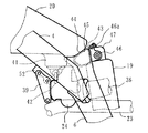
次に、後部クロス部材43の下方に形成されている空間56における部品のレイアウトにつき説明する。図6はこの部分を車体後方から示す図であり、この空間内には後部クロス部材43の近傍下方かつ車体左側へ寄った位置に気化器24が配設され、その右側に落とし込み部41及びその底部下方に設けられた燃料コック42が位置し、燃料コック42から下方へ延出する燃料チューブ42aは気化器24のフロート室24aへ接続されている。燃料コック42の高さはフロート室24aよりも若干高い程度である。
【0023】
またこれらの後方かつ車体中心の近傍にリヤクッション19が位置し、リヤクッション19に並設されたそのリザーブタンク19aの前方へ重なるように燃料コック42が位置している。さらに燃料コック42及びリザーブタンク19aの各下方を通って排気管23が配設されている。排気管23の前部はシリンダヘッド27の前部から斜め右側で出てから再び車体内側へ曲がり直して(図5参照)、その後右側のピボットプレート6の内側かつ前記したように燃料コック42及びリザーブタンク19aの各下方を通り、その後やや車体右側かつ上方へ曲がりながら後方へ延びている。なお、気化器24へ接続するコンチューブ(本図では省略)と排気管23はそれぞれリヤクッション19の左右両側へ分かれて配設される。
【0024】
次に、図7乃至図10により車体フレーム1の構造を詳述する。メインフレーム4はアルミ合金等を角形縦長断面をなすように押し出して形成される部材であり、その前端部はヘッドパイプ3へ溶接され、かつ後端部はピボットプレート6の上部と溶接されている。
【0025】
ダウンチューブ5はアルミ合金等の角形パイプからなり、その下部の後面側をスウェージング加工によりテーパー状に形成したものであり、その後面上部と左右のメインフレーム4の各中間部下面とを側面視略水平で、平面視前方へ凸のアーチ状をなすテンションパイプ50で連結補強してある。
【0026】
テンションパイプ50の前端部はガセット51でダウンチューブ5と結合され、テンションパイプ50の後端部とメインフレーム4の溶接部にはハンガブラケット39の取付ステー52が設けられている。ダウンチューブ5の下部はジョイント部材53を介して左右へ分かれるアルミ合金等の角形パイプからなる下部フレーム7の前端部が溶接されている(図8、図9参照)。
【0027】
図10はダウンチューブ5の横断面であり、4面のうち前面60の内面中央には長さ方向へ連続するリブ61が一体に形成されている。後面62は下半部側が後述するテーパー状部62bをなし、下方へ向かって次第に細くなっている。但し、上半部側の後面上部62aはストレート部になっている。また、左右の側面63の各外表面には右L字状をなすラジエタ取付部64が溶接され、ここにウエルドナット65が設けられ、左右のラジエタ22をボルト止めするようになっている。
【0028】
図7に明らかなように、テーパー状部62bは後面62にのみ設けられ、その後方かつシリンダヘッド27及びシリンダヘッドカバー28の前部との間に空間57b(図2参照)を拡大形成している。なお、他の部分である後面上部62a、前面60及び左右の側面63はテーパー状でなく、全てストレートな面になっている。すなわち、テーパー状部62bの存在により側面視にてダウンチューブ5は非対称に形成されている。
【0029】
このような形状にダウンチューブ5を成形するには、予めリブ61等を一体に形成するような所定断面の角断面パイプとして押し出し成形し、これを直交4方向からのみ圧縮するスエージング加工を施すことにより、特定の面のみを必要長さだけテーパー状に形成することができる。このようなスエージング加工は公知であり、かつこのようにすることにより、一断面内で一部を任意に偏肉させることができ、本実施例のリブ61も容易に形成できる。
【0030】
ピボットプレート6はアルミ合金等を鋳造又は鍛造等により製造した板状部材であり、その上端部はメインフレーム4の後端部よりも上方へ突出する上方延出部54をなし、この部分は左右それぞれが内側へ傾斜している(図8,図9参照)。左右の上方延出部54における内側対向面には凹部が形成され、ここに後部クロス部材43の両端が嵌合されて溶接されている。また、左右のピボットプレート6の中間部下方側位置にピボット受け部55が設けられ、ここにピボット軸15の両端が支持される。
【0031】
後部クロス部材43はアルミ合金等を鋳造や鍛造等により得られた中空の部材であり、この上面44は燃料タンク20の後端部45を乗せて支持する支持部をなしている。また、中央部には後方へ二股状に突出するクッションブラケット46が一体に形成され、ここにリヤクッション19の上端47が回動自在に支持されている。このクッションブラケット46は、若干車体中心Cよりオフセットされているが、このオフセットが最小となる位置に設けられる。また、クッションブラケット46の上部にはシートレール8を取付けるための取付穴46a(図4)が形成されている。
【0032】
後部クロス部材43の下方かつ左右のピボットプレート6及び下方のピボット軸15で挟まれた空間56(図6)は極めて大きな連続する空間をなし、ここに図6で前記したようにリヤクッション19及び排気管23、コンチューブ36が配設されている。また、後部クロス部材43より前方の空間もテンションパイプ50より上方かつヘッドパイプ3より後方に連続する大きな燃料タンク収容空間57(図8)として形成され、その一部でエンジン2のシリンダヘッドカバー28より後方側がシリンダ後方の空間57aをなしている(図3)。
【0033】
なお、図8及び図9における符号58はヘッドパイプ3と一体に形成されたブラケット40の取付ボスであり、59はヘッドパイプ3の後部を後方へ張り出して一体に形成したクロス部であり、左右のメインフレーム4の接合部を確保している。また、図7中の符号53aはジョイント部材53に設けられたエンジン支持用のステー、同じく7aは下部フレーム7に設けられたエンジン支持用のステーである。
【0034】
次に、本実施例の作用を説明する。図2及び図4に示すように、燃料タンク20の後方下部に下方へ突出する落とし込み部41を設けたのでこの部分を容量部として利用でき、燃料タンク20の容量増大が可能となる。また燃料タンク20を大容量にしても上方へ寸法拡大しないで済むので、それだけライディングポジションやシート21を車体前方へ設定できるとともに、燃料タンク20内の燃料残量変化や車体姿勢の変化による燃料の移動による重心の変動を小さくできる。
【0035】
しかも、図3及び図6に示すように、落とし込み部41を気化器24と車幅方向へ併設することにより、気化器24側方の空間57aを有効に活用できる。またこの空間57aはシリンダヘッド27、シリンダヘッドカバー28の後方及び後部クロス部材43の前方に形成されるので、4サイクルエンジンでシリンダヘッド27、シリンダヘッドカバー28の位置が高くなっているところ、その後方に形成される空間57aを有効に活用でき、4サイクルエンジンに好適な配置となる。
【0036】
さらに、燃料コック42を落とし込み部41の下方へ設けることにより、燃料コック42も気化器24の側方へ併設されることになり、燃料コック42も気化器24側方の空間57aを有効に活用してそのレイアウトの自由度を大きくできるとともに、フロート室24aに近接するような低い位置に設けることができので、燃料コック42から気化器24へ接続する燃料チューブ42aを可及的に短くして配管を容易にできる。さらに燃料コック42が最も低い位置に存在するので、残燃料の少ないときでも油面変動による空気の吸い込みを生じにくくなる。
【0037】
そのうえ、図6に明らかなように、燃料コック42の下方に排気管23の空間を配管部としたので、排気管23をこの空間及びリザーブタンク19aの下方へ配管するすることにより、排気管23の配管を容易とし、スペース効率よく容易にレイアウトできる。
【0038】
しかも、図4に明らかなように、燃料コック42の下部がメインフレーム4の下縁近傍に位置するので、メインフレーム4が縦長断面のものであっても燃料コック42を手の届きやすい位置に配設でき、本実施例では気化器24の配設されている車体左側と反対側になる車体右側より容易に操作でき、気化器24等の存在に邪魔されずにメンテナンスできるので、メンテナンス性に優れたものになる。
【図面の簡単な説明】
【図1】本実施例に係るオフロード型自動2輪車の要部側面図
【図2】エンジン上方における一部の部品配置を車体側面側から示す図
【図3】同様部品における一部部品の平面レイアウトを示す図
【図4】ピボットプレート上部における一部部品のレイアウトを車体側面から示す図
【図5】ダウンチューブ回りの部品配置を示す図
【図6】後部クロス部材下方の空間における部品配置を示す図
【図7】車体フレーム要部の側面図
【図8】その前半部側を上方から示す図
【図9】その後方視図
【図10】図7の10−10線断面図
【符号の説明】
1:車体フレーム、2:エンジン、3:ヘッドパイプ、4:メインフレーム、5:ダウンチューブ、6:ピボットプレート、7:下部フレーム、19:リヤクッション、20:燃料タンク、23:排気管、24:気化器、25:エアクリーナ、27:シリンダヘッド、36:コンチューブ、41:落とし込み部、42:燃料コック、43:後部クロス部材、44:上面、54:上方延出部、57:燃料タンク収容空間、57a:気化器と落とし込み部を収容する空間[0001]
BACKGROUND OF THE INVENTION
The present invention relates to a fuel tank arrangement structure in a motorcycle.
[0002]
[Prior art]
In Japanese Patent Publication No. 8-5419, the fuel tank is supported on a pair of left and right main frames disposed in the front-rear direction above the engine, and a recess is provided on the lower side surface of the fuel tank. A motorcycle with a fuel cock in the vicinity of the upper surface is shown.
[0003]
[Problems to be solved by the invention]
By the way, it is desirable to arrange the fuel tank as low as possible in order to lower the center of gravity of the vehicle body. However, in order to supply fuel from the fuel tank to the carburetor by gravity drop, the height of the cylinder head of the engine is limited.
[0004]
Therefore, if the fuel tank is expanded upward to ensure a certain large capacity, the riding position and the seat shape are restricted. In addition, the change in the center of gravity due to the movement of the fuel due to the change in the remaining amount in the fuel tank and the change in the vehicle body posture becomes large. Further, if the fuel tank is accommodated between the pair of left and right main frames, it becomes difficult to provide the fuel cock at a position where maintenance is good. The present invention aims to solve such problems.
[0005]
[Means for Solving the Problems]
In order to solve the above-described problem, the motorcycle fuel tank arrangement structure according to the present invention is a motorcycle in which a fuel tank is arranged above the engine.
A carburetor provided at a position below the fuel tank and toward the left or right side of the vehicle body;
A drop part formed in the fuel tank and projecting downward at a position close to the other side of the vehicle body is arranged in parallel in the vehicle width direction .
The fuel tank is accommodated between a pair of left and right main frames disposed in the front-rear direction above the engine, and the drop portion is provided below the rear portion of the fuel tank. Arranged in the space provided in front of the cross member connecting between the main frames,
The vaporizer and the drop-in portion are both disposed between the left and right main frames, and both the vaporizer and the drop-down portion overlap the main frame in a side view .
[0006]
【The invention's effect】
According to the present invention, the carburetor provided at a position below the fuel tank and toward one of the left and right sides of the vehicle body, and a drop portion formed on the fuel tank and projecting downward at a position near the other vehicle body The drop part is placed in the space provided behind the cylinder head of the engine and in front of the cross member connecting the left and right main frames, and the carburetor and drop part are both placed between the left and right main frames. Since the carburetor and the drop-in part overlap with the main frame when viewed from the side , the fuel cock can be provided at the theoretically lowest position, and the rear part of the fuel tank is provided below the center of the vehicle. be able to. Therefore, the riding position and seat can be set in front of the vehicle body, the capacity of the fuel tank can be increased, and the center of gravity can be stabilized. In addition, by arranging the drop-in portion and the vaporizer in the vehicle width direction, the arrangement in the lower position is facilitated, and the degree of freedom in layout is increased. Further, when the fuel cock is provided at the bottom of the dropping portion, the fuel cock is present at the lowest position, so that it is difficult for air to be sucked in due to oil level fluctuation even when there is little remaining fuel.
[0007]
DETAILED DESCRIPTION OF THE INVENTION
Embodiments will be described below with reference to the drawings. FIG. 1 is a side view of an essential part of an off-road type motorcycle according to the present embodiment, FIG. 2 is a view showing the arrangement of components above the engine from the side of the vehicle body, and FIG. FIG. 4 is a view showing the layout of some parts of the upper part of the pivot plate from the side of the vehicle body, FIG. 5 is a view showing the layout of some parts from the rear of the vehicle body frame, and FIG. FIG. 7 is a side view of the main part of the vehicle body frame, FIG. 8 is a plan view of the front half thereof, FIG. 9 is a rear view thereof, and FIG. 10 is a cross-sectional view taken along line 10-10 of FIG. .
[0008]
First, in FIG. 1, a
[0009]
A pair of left and right front forks 11 that are steered by a
[0010]
A front end of the rear swing arm 16 is swingably supported by a
[0011]
[0012]
As shown in FIG. 2, the engine 2 is a water-cooled four-cycle type, the
[0013]
[0014]
Further, the
[0015]
The connecting
[0016]
The
[0017]
Darken
[0018]
As is clear from FIG. 4, the position of the
[0019]
As shown in FIG. 1, the engine 2 is supported by the
[0020]
Next, the layout of parts in the vicinity of the
[0021]
Also, water-
[0022]
Next, the layout of components in the
[0023]
Further, a
[0024]
Next, the structure of the
[0025]
The down
[0026]
A front end portion of the
[0027]
FIG. 10 is a transverse cross section of the
[0028]
As apparent from FIG. 7, the tapered
[0029]
In order to form the
[0030]
The
[0031]
The
[0032]
A space 56 (FIG. 6) sandwiched between the left and
[0033]
8 and 9,
[0034]
Next, the operation of this embodiment will be described. As shown in FIGS. 2 and 4, since the dropping
[0035]
In addition, as shown in FIGS. 3 and 6, the
[0036]
Further, by providing the
[0037]
In addition, as clearly shown in FIG. 6, the space of the
[0038]
Moreover, as clearly shown in FIG. 4, since the lower portion of the
[Brief description of the drawings]
FIG. 1 is a side view of an essential part of an off-road motorcycle according to an embodiment of the present invention. FIG. 2 is a diagram showing the arrangement of some parts above the engine from the side of the vehicle body. FIG. FIG. 4 is a view showing the layout of some parts at the top of the pivot plate from the side of the vehicle body. FIG. 5 is a view showing the arrangement of parts around the down tube. FIG. 6 is a part in the space below the rear cross member. Fig. 7 is a side view of the main part of the vehicle body frame. Fig. 8 is a diagram showing the front half side from above. Fig. 9 is a rear view thereof. Fig. 10 is a sectional view taken along line 10-10 in Fig. 7. Explanation of symbols]
1: body frame, 2: engine, 3: head pipe, 4: main frame, 5: down tube, 6: pivot plate, 7: lower frame, 19: rear cushion, 20: fuel tank, 23: exhaust pipe, 24 : Vaporizer, 25: Air cleaner, 27: Cylinder head, 36: Con tube, 41: Drop-in part, 42: Fuel cock, 43: Rear cross member, 44: Upper surface, 54: Upper extension part, 57: Fuel tank accommodation Space, 57a: space for storing the vaporizer and drop-in part
Claims (6)
燃料タンクの下方、かつ車体の左右一方へ寄った位置に設けた気化器と、
燃料タンクに形成され、車体他方に寄った位置で下方へ突出する落とし込み部とを車幅方向へ並設するとともに、
前記燃料タンクはエンジンの上方を前後方向へ配設され左右一対のメインフレーム間に収容され、この燃料タンクの後部下方に前記落とし込み部を設け、この落とし込み部をエンジンのシリンダヘッド後方かつ前記左右メインフレーム間を連結するクロス部材の前方に設けられた空間内へ配置し、
前記気化器と落とし込み部をともに左右のメインフレーム間に配置し、側面視でこれら気化器と落とし込み部が共にメインフレームと重なることを特徴とする自動2輪車燃料タンク配置構造。In a motorcycle fuel tank arrangement structure in which a fuel tank is arranged above the engine,
A carburetor provided at a position below the fuel tank and toward the left or right side of the vehicle body;
A drop part formed in the fuel tank and projecting downward at a position close to the other side of the vehicle body is arranged in parallel in the vehicle width direction .
The fuel tank is disposed in the front-rear direction above the engine and is accommodated between a pair of left and right main frames. The drop portion is provided below the rear portion of the fuel tank, and the drop portion is disposed behind the cylinder head of the engine and the left and right main frames. Arranged in the space provided in front of the cross member that connects the frames,
A motorcycle fuel tank arrangement structure characterized in that both the carburetor and the drop-in part are arranged between the left and right main frames, and both the carburetor and the drop-in part overlap the main frame in a side view .
前記ダウンチューブに左右対に支持されるラジエタと
前記ラジエタからウォーターポンプに延びる送水ホースとをさらに備え、
前記排気管が前記ラジエタ下方を通って前記送水ホース外側を迂回して車体側方から前記配管空間に延びることを特徴とする請求項2に記載した自動2輪車燃料タンク配置構造。Further comprising: a down tube extending obliquely downward along the center of the vehicle body in front of the engine; a radiator supported by the left and right pairs on the down tube; and a water supply hose extending from the radiator to a water pump,
The motorcycle fuel tank arrangement structure according to claim 2 , wherein the exhaust pipe passes under the radiator and bypasses the outside of the water supply hose and extends from the side of the vehicle body to the piping space.
Priority Applications (5)
| Application Number | Priority Date | Filing Date | Title |
|---|---|---|---|
| JP2000096803A JP3766579B2 (en) | 2000-03-31 | 2000-03-31 | Motorcycle fuel tank arrangement structure |
| AT01107632T ATE325742T1 (en) | 2000-03-31 | 2001-03-27 | MOUNTING STRUCTURE OF A FUEL COCK IN A MOTORCYCLE |
| EP01107632A EP1138584B1 (en) | 2000-03-31 | 2001-03-27 | Structure for mounting a fuel cock in a motorcycle |
| ES01107632T ES2260112T3 (en) | 2000-03-31 | 2001-03-27 | STRUCTURE FOR MOUNTING A FUEL SPIT ON A MOTORCYCLE. |
| US09/820,991 US6640921B2 (en) | 2000-03-31 | 2001-03-30 | Structure for mounting fuel cock in motorcycle |
Applications Claiming Priority (1)
| Application Number | Priority Date | Filing Date | Title |
|---|---|---|---|
| JP2000096803A JP3766579B2 (en) | 2000-03-31 | 2000-03-31 | Motorcycle fuel tank arrangement structure |
Related Child Applications (1)
| Application Number | Title | Priority Date | Filing Date |
|---|---|---|---|
| JP2005234799A Division JP4256370B2 (en) | 2005-08-12 | 2005-08-12 | Exhaust pipe arrangement structure for motorcycles |
Publications (3)
| Publication Number | Publication Date |
|---|---|
| JP2001278152A JP2001278152A (en) | 2001-10-10 |
| JP2001278152A5 JP2001278152A5 (en) | 2005-06-09 |
| JP3766579B2 true JP3766579B2 (en) | 2006-04-12 |
Family
ID=18611518
Family Applications (1)
| Application Number | Title | Priority Date | Filing Date |
|---|---|---|---|
| JP2000096803A Expired - Fee Related JP3766579B2 (en) | 2000-03-31 | 2000-03-31 | Motorcycle fuel tank arrangement structure |
Country Status (5)
| Country | Link |
|---|---|
| US (1) | US6640921B2 (en) |
| EP (1) | EP1138584B1 (en) |
| JP (1) | JP3766579B2 (en) |
| AT (1) | ATE325742T1 (en) |
| ES (1) | ES2260112T3 (en) |
Families Citing this family (11)
| Publication number | Priority date | Publication date | Assignee | Title |
|---|---|---|---|---|
| WO2003035459A1 (en) * | 2001-10-19 | 2003-05-01 | Honda Giken Kogyo Kabushiki Kaisha | Fixing structure of fuel cock in motorcycle |
| JP2004098884A (en) * | 2002-09-10 | 2004-04-02 | Honda Motor Co Ltd | Rear part structure for motorcycle |
| JP2005083286A (en) * | 2003-09-09 | 2005-03-31 | Honda Motor Co Ltd | Exhaust apparatus |
| US7637345B2 (en) * | 2004-12-24 | 2009-12-29 | Kawasaki Jukogyo Kabushiki Kaisha | Frame of motorcycle and engine bracket |
| JP4630754B2 (en) * | 2005-06-30 | 2011-02-09 | 本田技研工業株式会社 | Motorcycle frame |
| JP4853900B2 (en) * | 2006-02-23 | 2012-01-11 | 本田技研工業株式会社 | Body frame structure for motorcycles |
| JP2008222010A (en) * | 2007-03-13 | 2008-09-25 | Yamaha Motor Co Ltd | Vehicle |
| US20080277898A1 (en) * | 2007-05-10 | 2008-11-13 | Julia Chu | Reinforced motorcycle frame |
| JP5112092B2 (en) | 2008-01-31 | 2013-01-09 | 本田技研工業株式会社 | Rear frame mounting structure for motorcycles |
| ATE542733T1 (en) * | 2009-01-26 | 2012-02-15 | Yamaha Motor Europ | MOTORCYCLE WITH A SPECIAL ARRANGEMENT OF FUEL TANK, FUEL PUMP AND AIR FILTER |
| JP6202516B2 (en) * | 2013-01-31 | 2017-09-27 | 本田技研工業株式会社 | Saddle riding |
Family Cites Families (18)
| Publication number | Priority date | Publication date | Assignee | Title |
|---|---|---|---|---|
| JPS51132557A (en) * | 1975-05-14 | 1976-11-17 | Honda Motor Co Ltd | Device for preventing fuel from leaking when vehicle is overturned |
| JPS5510042A (en) * | 1978-07-05 | 1980-01-24 | Yamaha Motor Co Ltd | Fuel controller for motorcycle |
| US4577719A (en) * | 1979-06-29 | 1986-03-25 | Yamaha Hatsudoki Kabushiki Kaisha | Motorcycle fuel system with flow from a main tank through a lower auxiliary tank to its engine |
| JPS56152558A (en) * | 1980-04-22 | 1981-11-26 | Yukio Okuno | Production method by division of work for multiple kind of article at multiple process |
| JPS6027837Y2 (en) * | 1980-11-15 | 1985-08-22 | 本田技研工業株式会社 | Connection device between diaphragm and operating rod |
| JPS57113953A (en) * | 1980-12-29 | 1982-07-15 | Yamaha Motor Co Ltd | Mechanically driven fuel pump in motorcycle |
| JPS6181874A (en) * | 1984-09-17 | 1986-04-25 | 本田技研工業株式会社 | Fuel tank for saddling type car |
| US4781264A (en) * | 1984-10-12 | 1988-11-01 | Honda Giken Kogyo Kabushiki Kaisha | Motor vehicle with riding saddle and horizontally disposed cushioning unit |
| US4653762A (en) * | 1984-12-27 | 1987-03-31 | Honda Giken Kogyo Kabushiki Kaisha | Fuel tank and fuel feed system for a motorcycle |
| US4799569A (en) * | 1985-08-23 | 1989-01-24 | Honda Giken Kogyo Kabushiki Kaisha | Motorcycle |
| JPH085419B2 (en) * | 1985-10-02 | 1996-01-24 | ヤマハ発動機株式会社 | Fuel cock mounting structure for motorcycles |
| US4799565A (en) * | 1986-10-23 | 1989-01-24 | Honda Giken Kogyo Kabushiki Kaisha | Fuel supply system for off-road vehicle |
| US5012883A (en) * | 1988-03-20 | 1991-05-07 | Honda Giken Kogyo Kabushiki Kaisha | Air duct device for a motorcycle |
| US5145023A (en) * | 1988-06-10 | 1992-09-08 | Honda Giken Kogyo Kabushiki Kaisha | Motorcycle fuel tank providing multiple enhancements |
| JP3034535B2 (en) * | 1989-07-25 | 2000-04-17 | 本田技研工業株式会社 | Muffler device for motorcycle |
| US5147077A (en) * | 1990-01-25 | 1992-09-15 | Suzuki Kabushiki Kaisha | Storage box compartment means for a motorcycle |
| JP3013592B2 (en) * | 1992-04-27 | 2000-02-28 | スズキ株式会社 | Motorcycle fuel cock mounting structure |
| EP0849149B1 (en) * | 1996-12-20 | 2004-05-19 | Suzuki Kabushiki Kaisha | Fuel tank system of a motor bicycle |
-
2000
- 2000-03-31 JP JP2000096803A patent/JP3766579B2/en not_active Expired - Fee Related
-
2001
- 2001-03-27 ES ES01107632T patent/ES2260112T3/en not_active Expired - Lifetime
- 2001-03-27 AT AT01107632T patent/ATE325742T1/en not_active IP Right Cessation
- 2001-03-27 EP EP01107632A patent/EP1138584B1/en not_active Expired - Lifetime
- 2001-03-30 US US09/820,991 patent/US6640921B2/en not_active Expired - Fee Related
Also Published As
| Publication number | Publication date |
|---|---|
| US6640921B2 (en) | 2003-11-04 |
| ES2260112T3 (en) | 2006-11-01 |
| US20010030072A1 (en) | 2001-10-18 |
| ATE325742T1 (en) | 2006-06-15 |
| EP1138584A2 (en) | 2001-10-04 |
| EP1138584B1 (en) | 2006-05-10 |
| EP1138584A3 (en) | 2004-09-08 |
| JP2001278152A (en) | 2001-10-10 |
Similar Documents
| Publication | Publication Date | Title |
|---|---|---|
| JP3766580B2 (en) | Manufacturing method of body frame for motorcycle | |
| JP3907375B2 (en) | Body frame for motorcycles | |
| JP2001278159A5 (en) | ||
| JP3990551B2 (en) | Motorcycle frame structure | |
| JP4364362B2 (en) | Motorcycle frame structure | |
| JP3766579B2 (en) | Motorcycle fuel tank arrangement structure | |
| JP4785557B2 (en) | Exhaust structure of motorcycle | |
| JP2008222078A (en) | Motorcycle | |
| JP2010083308A (en) | Motorcycle | |
| JP4368596B2 (en) | Body structure of motorcycle | |
| US20180313304A1 (en) | Saddle-ridden vehicle | |
| JP4256370B2 (en) | Exhaust pipe arrangement structure for motorcycles | |
| JP2001278152A5 (en) | ||
| JP4152998B2 (en) | Body frame for motorcycles | |
| JP2006193026A (en) | Motorcycle | |
| JP2979015B2 (en) | Motorcycle | |
| JP4364361B2 (en) | Motorcycle | |
| JP4398790B2 (en) | Frame structure in motorcycle | |
| JP2511989Y2 (en) | Rear wheel suspension for motorcycles | |
| JP2000225980A (en) | Scooter type motorcycle | |
| JPH0641270B2 (en) | Motorcycle frame | |
| JPH0853093A (en) | Air feed structure to intake device of astride-riding type vehicle | |
| JPH048276B2 (en) | ||
| JPH04292283A (en) | Body frame of motorcycle | |
| JPH01229791A (en) | Motorcycle |
Legal Events
| Date | Code | Title | Description |
|---|---|---|---|
| A521 | Request for written amendment filed |
Free format text: JAPANESE INTERMEDIATE CODE: A523 Effective date: 20040823 |
|
| A977 | Report on retrieval |
Free format text: JAPANESE INTERMEDIATE CODE: A971007 Effective date: 20050531 |
|
| A131 | Notification of reasons for refusal |
Free format text: JAPANESE INTERMEDIATE CODE: A131 Effective date: 20050614 |
|
| A521 | Request for written amendment filed |
Free format text: JAPANESE INTERMEDIATE CODE: A523 Effective date: 20050812 |
|
| A131 | Notification of reasons for refusal |
Free format text: JAPANESE INTERMEDIATE CODE: A131 Effective date: 20051025 |
|
| A521 | Request for written amendment filed |
Free format text: JAPANESE INTERMEDIATE CODE: A523 Effective date: 20051226 |
|
| TRDD | Decision of grant or rejection written | ||
| A01 | Written decision to grant a patent or to grant a registration (utility model) |
Free format text: JAPANESE INTERMEDIATE CODE: A01 Effective date: 20060124 |
|
| A61 | First payment of annual fees (during grant procedure) |
Free format text: JAPANESE INTERMEDIATE CODE: A61 Effective date: 20060127 |
|
| R150 | Certificate of patent or registration of utility model |
Free format text: JAPANESE INTERMEDIATE CODE: R150 |
|
| FPAY | Renewal fee payment (event date is renewal date of database) |
Free format text: PAYMENT UNTIL: 20100203 Year of fee payment: 4 |
|
| FPAY | Renewal fee payment (event date is renewal date of database) |
Free format text: PAYMENT UNTIL: 20100203 Year of fee payment: 4 |
|
| FPAY | Renewal fee payment (event date is renewal date of database) |
Free format text: PAYMENT UNTIL: 20110203 Year of fee payment: 5 |
|
| FPAY | Renewal fee payment (event date is renewal date of database) |
Free format text: PAYMENT UNTIL: 20110203 Year of fee payment: 5 |
|
| FPAY | Renewal fee payment (event date is renewal date of database) |
Free format text: PAYMENT UNTIL: 20120203 Year of fee payment: 6 |
|
| LAPS | Cancellation because of no payment of annual fees |