JP2001183930A5 - - Google Patents
Download PDFInfo
- Publication number
- JP2001183930A5 JP2001183930A5 JP1999370154A JP37015499A JP2001183930A5 JP 2001183930 A5 JP2001183930 A5 JP 2001183930A5 JP 1999370154 A JP1999370154 A JP 1999370154A JP 37015499 A JP37015499 A JP 37015499A JP 2001183930 A5 JP2001183930 A5 JP 2001183930A5
- Authority
- JP
- Japan
- Prior art keywords
- film
- stay
- heating
- recording material
- heating element
- Prior art date
- Legal status (The legal status is an assumption and is not a legal conclusion. Google has not performed a legal analysis and makes no representation as to the accuracy of the status listed.)
- Pending
Links
- 238000010438 heat treatment Methods 0.000 description 31
- 239000010408 film Substances 0.000 description 25
- 239000000463 material Substances 0.000 description 12
- 239000000758 substrate Substances 0.000 description 5
- 230000002093 peripheral Effects 0.000 description 4
- KDLHZDBZIXYQEI-UHFFFAOYSA-N palladium Substances [Pd] KDLHZDBZIXYQEI-UHFFFAOYSA-N 0.000 description 2
- 238000011144 upstream manufacturing Methods 0.000 description 2
- PNEYBMLMFCGWSK-UHFFFAOYSA-N AI2O3 Inorganic materials [O-2].[O-2].[O-2].[Al+3].[Al+3] PNEYBMLMFCGWSK-UHFFFAOYSA-N 0.000 description 1
- 230000037250 Clearance Effects 0.000 description 1
- 229910019899 RuO Inorganic materials 0.000 description 1
- PIGFYZPCRLYGLF-UHFFFAOYSA-N aluminum nitride Chemical compound [Al]#N PIGFYZPCRLYGLF-UHFFFAOYSA-N 0.000 description 1
- 230000035512 clearance Effects 0.000 description 1
- 238000001514 detection method Methods 0.000 description 1
- 238000010586 diagram Methods 0.000 description 1
- 230000000694 effects Effects 0.000 description 1
- 229910052763 palladium Inorganic materials 0.000 description 1
- 238000007650 screen-printing Methods 0.000 description 1
- 239000010409 thin film Substances 0.000 description 1
- 238000003466 welding Methods 0.000 description 1
- 230000037303 wrinkles Effects 0.000 description 1
Images


Description
図16は最大通紙幅がA3サイズであるフィルム加熱定着方式による従来の加熱装置を示す概略構成図である。101はステーであり、このステー101は加熱体103を露呈させて支持した横断面U字状の本体部105と該本体部を対向する加圧ローラ104側へ加圧する加圧部106とで構成されている。102はステー101に外嵌させてある横断面円形の耐熱性フィルム(以下、フィルムと略称する)である。
FIG. 16 is a schematic configuration diagram showing a conventional heating device by a film heating fixing method having a maximum paper passing width of A3 size.
図15は上記加熱体103の途中を省略し、一部切り欠いた平面図である。この加熱体103はフィルム102もしくは被加熱体としての紙等の記録材Pの搬送方向aに対して直角方向を長手とする細長の耐熱性・絶縁性・良熱伝導性の基板131、この基板131の表面側の短手方向中央部に基板長手に沿って形成具備させた抵抗発熱体132、この抵抗発熱体を形成した加熱体表面を保護させた耐熱性オーバーコート層134、抵抗発熱体132の長手両端部の給電用電極133・133とともに、基板裏面側に具備させた加熱体温度を検知するサーミスタ等の検温素子107等からなる全体に低熱容量の線状加熱体を基板構成体とする。この加熱体103は抵抗発熱体132を図16において、剛性・耐熱性を有するステー本体部105の下面側に下向きに露呈させて固定配設してある。
FIG. 15 is a plan view in which the middle of the
上記加熱体103の基板131は、例えば、アルミナや窒化アルミニウム等の厚み1mm・幅10mm・長さ330mmのものである。また、抵抗発熱体132は例えば、Ag/Pd(銀パラジウム)、RuO2、Ta2N等の電気抵抗材料をスクリーン印刷等により、厚み約10μm、幅1〜3mmの線状もしくは細帯状に塗工して形成したものである。
The
この種の所謂テンションレスタイプの加熱装置は、例えば特開平4−44075号公報〜特開平4−44083号公報、特開平4−204980号公報〜特開平4−204984号公報等に開示されている。 This kind of so-called tensionless type heating device is disclosed in, for example, JP-A-4-44075 to JP-A-4-44083, JP-A-4-204980 to JP-A-4-204984, and the like. ..
即ち、検温素子107の検知温度が所定の設定温度より低いと加熱体103が昇温するように、また、高い場合は加熱体103が降温するように通電を制御することで加熱体103は定着時、一定の温度に調整される。而して、加熱体103の温度が所定に立ち上がり、かつ加圧ローラ104の回転によるフィルム102の回転周速度が定常化した状態において、画像定着すべき記録材Pが加熱体103と加圧ローラ104とで形成される圧接ニップ部Nを挟持搬送されることにより、加熱体103の熱がフィルム102を介して記録材Pに付与され、記録材P上の未定着顕画像(トナー画像)tが記録材P面に加熱定着される。そして、圧接ニップ部Nを通った記録材Pはフィルム102の面から分離されて搬送される。
That is, the
上記フィルム102はステー101に対し周長が余裕を持ってルーズに外嵌しているため図17に示すようにフィルム102とステー101の間に隙間を持っており、記録材Pがニップ部Nに侵入する前、フィルム102はステー101に対し図17(a)に示す端部、図17(b)に示す中央部ともに同じ隙間S 0 を持って回転している。
Since the
すると、加圧ローラ104の周速も非通紙部の方が速くなる。つまり、ニップ部Nでのフィルム102の搬送速度が通紙部より非通紙部の方が大きくなり、速度差が生じ、フィルム102は通紙部と非通紙部でねじれ力が働き、ニップ部Nの直前でフィルム102とステー101の間の隙間量が端部では図18(a)に示すように隙間S1と小さく、中央部では図18(b)に示すように隙間S2と大きくなり、S 2 >S0>S 1 という関係になるため、図11に示すようにニップ部Nの直前でフィルム102が102’のようにたるんだ状態になる。
Then, the peripheral speed of the pressurizing
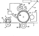
図において、1はフィルム支持手段としてのステーであり、このステー1は加熱体3を露呈させて支持した横断面U字状のフィルムガイド5と、このフィルムガイド5に組み付け、該ガイド5を対向する加圧体としての加圧ローラ4側に加圧する横断面コの字状の加圧部6とから構成されている。2(図2)はステー1に外嵌させてある横断面円形の耐熱フィルム(薄膜フィルム)であり、このフィルム2は内周長が加熱体3を含むステーの外周長に対し例えば3mm程度大きくしてある。したがってステー1に対し周長に余裕をもってルーズに外嵌されている。このステー1はフィルム2を介して加圧ローラ4で長手方向全体に加圧され、ニップ部Nを形成している。
In the figure, reference numeral 1 denotes a stay as a film supporting means, and the stay 1 is attached to a
図3に示した加熱装置においても前述の図2に記載の本実施形態の加熱装置と同様に小サイズの紙シワを防止できるが、最大通紙幅であるA3サイズのように通紙幅が広い記録材を通紙すると、図5に示すように前述の大きいサイズのシワ対策である長手方向端部方向への引き延ばし効果により、加熱装置ニップ上流部において記録材端部がフィルム方向に盛り上がる。よって、加熱装置上流部において記録材上の未定着画像とフィルムが接触し、画像の乱れが発生することがある。 Although it is possible to prevent the creases of small size like the heating apparatus of the present embodiment shown in Figure 2 described above in the heating apparatus shown in FIG. 3, passing width is wide recorded as A3 size which is the maximum sheet passing width When the material is passed through the paper, as shown in FIG. 5, the recording material end portion rises in the film direction at the upstream portion of the heating device nip due to the stretching effect in the longitudinal direction end portion direction, which is a measure against wrinkles of a large size described above. Therefore, the unfixed image on the recording material may come into contact with the film in the upstream portion of the heating device, and the image may be distorted.
(第6の実施形態)
図13は第6の実施形態における加熱装置を示す概要図であり、(a)はニップ下流から見た斜視図、(b)と(c)はその一部の側面図である。
(Sixth Embodiment)
13A and 13B are schematic views showing a heating device according to a sixth embodiment, FIG. 13A is a perspective view seen from the downstream side of the nip, and FIGS. 13B and 13C are side views thereof.
【符号の説明】
1 ステー(フィルム支持手段)
2 フィルム
3 加熱体
4 加圧ローラ(加圧体)
5 フィルムガイド
5a,5b,5c,5d 突状部
6 加圧部
8 突状部
9 端部体
N ニップ部
P 記録材
[Explanation of symbols]
1 stay (film support means)
2
5
Priority Applications (1)
| Application Number | Priority Date | Filing Date | Title |
|---|---|---|---|
| JP37015499A JP2001183930A (en) | 1999-12-27 | 1999-12-27 | Heating device and image forming device |
Applications Claiming Priority (1)
| Application Number | Priority Date | Filing Date | Title |
|---|---|---|---|
| JP37015499A JP2001183930A (en) | 1999-12-27 | 1999-12-27 | Heating device and image forming device |
Publications (2)
| Publication Number | Publication Date |
|---|---|
| JP2001183930A JP2001183930A (en) | 2001-07-06 |
| JP2001183930A5 true JP2001183930A5 (en) | 2007-02-15 |
Family
ID=18496200
Family Applications (1)
| Application Number | Title | Priority Date | Filing Date |
|---|---|---|---|
| JP37015499A Pending JP2001183930A (en) | 1999-12-27 | 1999-12-27 | Heating device and image forming device |
Country Status (1)
| Country | Link |
|---|---|
| JP (1) | JP2001183930A (en) |
Families Citing this family (8)
| Publication number | Priority date | Publication date | Assignee | Title |
|---|---|---|---|---|
| JP4261714B2 (en) * | 1999-12-27 | 2009-04-30 | キヤノン株式会社 | Fixing device |
| JP2004281286A (en) * | 2003-03-18 | 2004-10-07 | Canon Inc | Heating device |
| JP4235493B2 (en) * | 2003-06-16 | 2009-03-11 | キヤノン株式会社 | Fixing device |
| JP2005242333A (en) | 2004-01-30 | 2005-09-08 | Canon Inc | Image heating apparatus provided with flexible sleeve |
| JP2007079507A (en) | 2005-09-16 | 2007-03-29 | Canon Inc | Heating device and image forming apparatus |
| JP6594043B2 (en) * | 2014-08-04 | 2019-10-23 | キヤノン株式会社 | Fixing device |
| JP6753148B2 (en) * | 2016-05-31 | 2020-09-09 | ブラザー工業株式会社 | Manufacturing method of fixing device and fixing device |
| JP6848523B2 (en) * | 2017-02-27 | 2021-03-24 | ブラザー工業株式会社 | Fixing device |
-
1999
- 1999-12-27 JP JP37015499A patent/JP2001183930A/en active Pending
Similar Documents
| Publication | Publication Date | Title |
|---|---|---|
| JP3161114B2 (en) | Heating equipment | |
| JPH07199703A (en) | Heating device | |
| JP6289344B2 (en) | Fixing device | |
| JP3483423B2 (en) | Heating equipment | |
| JP2001183930A5 (en) | ||
| US20080138129A1 (en) | Fuser Assembly Having Heater Element with Spaced-Apart Features | |
| JP4261714B2 (en) | Fixing device | |
| JP2001183930A (en) | Heating device and image forming device | |
| JP2008151923A (en) | Thermal fixing device | |
| JPH09152803A (en) | Pressure rotating body, fixing device, and image recorder | |
| JP2004252301A (en) | Image forming apparatus | |
| JPH06308854A (en) | Heating device | |
| JP2008275753A (en) | Thermal fixing device | |
| JP2000250337A (en) | Heating body, image heating device and image forming device | |
| JP2004077993A (en) | Heating device | |
| JPH0764420A (en) | Heat fixing device | |
| JP3056821B2 (en) | Fixing device | |
| JP2008275754A (en) | Thermal fixing device | |
| JP4164349B2 (en) | Image heating device | |
| JPH07181831A (en) | Fixing device | |
| JP3450637B2 (en) | Heating body and heating device | |
| JP2003084592A (en) | Thermal fixing device | |
| JP3368156B2 (en) | Heat fixing device | |
| JP2004047247A (en) | Electrode structure, heating body, heating device, and image forming apparatus | |
| JP3624991B2 (en) | Fixing apparatus and image forming apparatus |