【発明の名称】ロータリーカッタの制御装置
【特許請求の範囲】
【請求項1】走行する材料に追従して、材料を切断するロータリーカッタを減速,加速,定速駆動する電動機を制御する際に、制御応答の遅れにより、前記電動機の応答速度が速度指令に対して遅れるロータリーカッタ制御装置において、
前記速度指令に対する前記電動機の応答速度の遅れ分である整定時間を補償するために、前記整定時間に相当する時間だけ早く速度指令を生成し、この速度指令による電動機の応答速度に前記整定時間の遅れがないようにすることを特徴とするロータリーカッタの制御装置。
【請求項2】走行する材料の移動速度を検出して、前記移動速度を時間積分して材料の移動距離を求め、前記検出された移動速度から前記整定時間を補償する整定時間補償値を生成し、前記材料の移動距離と前記整定時間補償値とを加算し、この加算した値と、前記走行する材料を切断するために必要な諸条件である材料切断長,ロータリーカッタ切断領域の周長,およびロータリーカッタ周長の値とから、位置指令を演算し、この演算した位置指令を時間微分して前記速度指令を生成することを特徴とする請求項1に記載のロータリーカッタ制御装置。
【請求項3】前記速度指令が、定速間の変速領域において、減速から加速に移行させる速度指令である場合に、前記速度指令は、ロータリーカッタを減速から加速に移すときに、徐々に減速させた後、徐々に加速する速度指令であることを特徴とする請求項2に記載の制御装置。
【請求項4】走行する材料に追従して、材料を切断するロータリーカッタを減速,加速,定速駆動する電動機を制御する際に、制御応答の遅れにより、前記電動機の応答速度が速度指令に対して整定時間だけ遅れる制御装置において、
走行する材料の移動速度を検出するパルスジェネレータと、
前記移動速度を時間積分して材料の移動距離を求める積分器と、
前記検出された移動速度から前記整定時間を補償する整定時間補償値を生成する整定時間補償器と、
前記材料の移動距離と前記整定時間補償値とを加算する加算器と、
前記加算した値と、前記走行する材料を切断するために必要な諸条件である材料切断長,ロータリーカッタ切断領域の周長,およびロータリーカッタ周長の値とから、位置指令を演算する位置指令発生器と、
前記演算した位置指令を時間微分して前記速度指令を生成する微分器と、
を備えることを特徴とするロータリーカッタ制御装置。
【請求項5】前記速度指令が、定速間の変速領域において、減速から加速に移行させる速度指令である場合に、前記速度指令は、ロータリーカッタを減速から加速に移すときに、徐々に減速させた後、徐々に加速する速度指令であることを特徴とする請求項4に記載の制御装置。
【発明の詳細な説明】
【0001】
【発明の属する技術分野】
この発明は、連続的に高速で送られる鋼板,アルミニウム板,紙,段ボール等の材料を、数値制御により回転する刃物が材料に追従しながら切断し、切断と切断との間は、数値制御により刃物の回転を変速させて切断長を設定長に一致させるロータリーカッタの制御装置に関するものである。
【0002】
【従来の技術】
連続的に高速で送られる鋼板,アルミニウム板,紙,段ボール等の材料を切断する従来のロータリーカッタの制御装置のブロック図を図15に、従来の速度指令特性線図を図9に示す。
【0003】
図15に示すように、軸方向周面に刃を有する一対のロータリーカッタ2があり、このロータリーカッタ2の主軸3には減速ギヤー4が取りつけられ、ロータリーカッタ2を駆動するための電動機5が結合されている。この電動機5には、電動機の回転速度と電動機回転角、即ち、ロータリーカッタ2の主軸3の回転角を検出するためのパルスジェネレータ(PG)6が備えられている。
【0004】
一方、走行する材料1の移動量を検出するための測長ホイール8が備えられ、この測長ホイール8の軸には、移動量を検出するためのパルスジェネレータ(PG)9が備えられている。さらに、ロータリーカッタ2により走行する材料1を切断する毎に、切断完了位置を検出する切断完了位置センサ70が備えられている。このロータリーカッタ2の数値制御装置30は、特公昭61−33679号公報に開示されているように、大きく分けて定尺切断回路部40と、停止制御回路部60と、比較部53とにより構成されている。
【0005】
定尺切断回路部40は、材料1を設定された所定の長さに正確に切断するための回路であり、切断寸法設定部41,第1演算部42,切断完了センサ43,タイミング信号発生部44,周長設定部45,材料走行距離検出回路46,モータ回転数検出回路47,第2演算部48,D/A変換器49,関数発生器50,F/V変換器51,演算増幅器52で構成される。
【0006】
この定尺切断回路部では、ロータリーカッタ2により走行する材料1を切断する毎に、切断完了位置センサ70により切断完了位置を検出し、切断完了位置信号を発生する毎に、切断長L0 とロータリーカッタ2の周長B0 との差L=L0 −B0 に相当するパルス数を定尺切断回路部40の演算部48に読込む。
【0007】
材料1の走行に伴いパルスジェネレータ9より発生するパルス数Φa (即ち、材料の移動量)と、ロータリーカッタ2の回転に伴いパルスジェネレータ6より発生するΦb (ロータリーカッタ2の回転量)との差Φa −Φb 、即ち、R=L0 −B0 −(Φa −Φb )を計算しながら、差Rに相当する補償電圧Vc =f(R)と、パルスジェネレータ(PG)9の出力を周波数−電圧(F/V)変換して得られる電圧、即ち、材料1の移動量を表す電圧Va との差V0 =Va −Vc を、V0 >0の時だけ、電動機5の駆動制御回路7に速度指令として与える。
【0008】
停止制御回路部60は、停止距離設定部61,可逆カウンタ62,D/A変換器63,関数発生器64,比較部65により構成される。
【0009】
このような停止制御回路部では、ロータリーカッタ2の刃が切断完了位置センサ70を通過し、切断完了信号が発生する度に、可逆カウンタ62は、あらかじめ設定されたロータリーカッタ2の刃の停止距離に相当するパルス数Φs を読込むとともに、ロータリーカッタ2の回転量を表すパルス数Φb を減算し、D/A変換器64は、これに比例した直流電圧Vb に変換する。
【0010】
比較部53は、停止制御回路部60の比較部65の出力電圧V1 と、定尺切断回路40の演算増幅器52の出力する速度指令電圧V0 とを比較し、いずれか高い方を、最終指令電圧V2 として、駆動制御回路7に与える。
【0011】
以上のような数値制御装置30では、材料1の速度電圧Va に対して補償電圧Vc を減算して、差Rに従い材料1の速度に対して補償すると共に、切断時には差Rが零となってVc =0、即ち、Vc =Va としてロータリーカッタ2の速度を材料1の速度に同期させ、且つ、この間に、Φa ,Φb の何れか一方が他方に対して進みあるいは遅れると、その差を零にするように電動機を加減速制御をするデジタルサーボ制御を行うことによって、材料1を所定の長さに正確に定尺切断することができる。
【0012】
【発明が解決しようとする課題】
しかし、上記従来のロータリーカッタ制御装置には、次のような問題がある。すなわち、図9に示すように、加減速レートの速度指令(折線曲線)VR に対する電動機の速度応答VB は、制御応答の遅れのために、遅れる。この遅れの時間をtS で示す。したがって、カッタの速度が材料速度に同調する際に、tS 分遅れることになる。このような制御応答の遅れがあると切断長に誤差を生じるという問題がある。以下、この明細書では、前記遅れ時間tS を、整定時間と言うものとする。
【0013】
また、従来のロータリーカッタ制御装置では、加速および減速は直線的に行われ、加速時の加速レート、および減速時の減速レートは、D/A変換器のゲインによって決定されるため、固定値となる。
【0014】
加減速レートが固定値であると、切断長、材料の走行速度に関係なく加減速レートが一定のため、効率的な切断ができない問題があった。
【0015】
さらに、加速および減速が直線的であると、減速から加速に移行するような場合には、衝撃的な力が発生し、ギヤーの騒音,摩耗,破損等の障害を生じる。
【0016】
本発明者は、このような問題を解決するために、定速領域間の変速領域での速度指令を折線曲線ではなく、正弦曲線,2次曲線などの特性になるようにする制御装置を考案した。以降、本明細書では、変速領域での速度指令を表す曲線を変速曲線と言うものとする。
【0017】
変速曲線が折線曲線、あるいは上記のような正弦曲線,2次曲線等であろうと、制御応答の遅れは共通の問題である。
【0018】
本発明の目的は、上述のような問題を解決するためになされたもので、カッタ速度指令を整定時間相当早く生成して与え、電動機の速度応答を理想的な応答に一致させ、また、各々の変速曲線の特徴に応じた効率的な切断ができるロータリーカッタの制御装置を提供することにある。
【0019】
【課題を解決するための手段】
本発明は、走行する材料に追従して、材料を切断するロータリーカッタを減速,加速,定速駆動する電動機を制御する際に、制御応答の遅れにより、前記電動機の応答速度が速度指令に対して遅れるロータリーカッタ制御装置において、前記速度指令に対する前記電動機の応答速度の遅れ分である整定時間を補償するために、前記整定時間に相当する時間だけ早く速度指令を生成し、この速度指令による電動機の応答速度に前記整定時間の遅れがないようにすることを特徴とする。
【0020】
本発明は、さらに、走行する材料の移動速度を検出して、前記移動速度を時間積分して材料の移動距離を求め、前記検出された移動速度から前記整定時間を補償する整定時間補償値を生成し、前記材料の移動距離と前記整定時間補償値とを加算し、この加算した値と、前記走行する材料を切断するために必要な諸条件である材料切断長,ロータリーカッタ切断領域の周長,およびロータリーカッタ周長の値とから、位置指令を演算し、この演算した位置指令を時間微分して前記速度指令を生成することを特徴とする。
【0021】
本発明は、さらに、前記速度指令が、定速間の変速領域において、減速から加速に移行させる速度指令である場合に、前記速度指令は、ロータリーカッタを減速から加速に移すときに、徐々に減速させた後、徐々に加速する速度指令であることを特徴とする。
【0022】
【発明の実施の形態】
図1は、本発明のロータリーカッタの制御装置の構成を示すブロック図である。図1に示すように、軸方向周面に刃を有する一対のロータリーカッタ2があり、このカッタ2を駆動するための電動機5がギヤー4によりカッタの主軸3に結合されている。この電動機5には、電動機の回転角、即ち、カッタ2の回転角を検出するためのパルスジェネレータ(PG)6が備えられている。
【0023】
一方、走行する材料1の速度を検出するための測長ロール8が備えられ、この測長ロール8の軸には、パルスジェネレータ(PG)9が備えられている。
【0024】
測長ロール8は、走行する材料1の速度を検出するために、走行する材料1の両面を上下2本の測長ロール8で加圧接触、即ち、ニップし、材料の走行にしたがって生ずる測長ロール8の回転により、パルスジェネレータ9から単位回転毎にパルスを発生させ、そのパルスを計数することにより、連続走行する材料の速度VL を検出している。
【0025】
次に、数値制御装置80について説明する。この数値制御装置80は、整定時間補償器10、積分器11、位置指令発生器12、微分器13、積分器14、位置制御器15、速度制御器16、微分器18,19、乗算器17,20、機械定数乗算器21、加算器31〜37によって構成されている。
【0026】
材料1の走行に伴いパルスジェネレータ9より発生する材料速度VL を、数値制御装置80の整定時間補償器10(後に詳細に説明する)および積分器11に同時に入力する。整定時間補償器10に入力されたVL は、電動機の応答速度の遅れ分(tS )に相当する整定時間補償信号を出力し、積分器11の出力と共に加算器31により加算し、加算した値は、材料移動距離xとして位置指令発生器12に入力される。この位置指令発生器12は、材料移動距離xの関数として位置指令f(x)を与える。微分器13は、位置指令f(x)を時間微分することにより、カッタ速度指令df(x)/dtを出力する。
【0027】
一方、ロータリーカッタ2の回転に伴いパルスジェネレータ6より発生するパルスからロータリーカッタ2の移動速度VB が得られる。
【0028】
加算器32により、速度指令df(x)/dfと、材料速度VL と、カッタ速度VB とが加算され、積分器14に入力され、位置偏差eとして出力する。この位置偏差eは、
【0029】
【数1】
【0030】
で与えられる。この位置偏差eは、位置制御器15に入力され補償速度Vc として出力される。
【0031】
一方、乗算器17で、カッタ速度指令df(x)/dtにフィードフォワード定数αとを乗算することにより、速度指令フィードフォワード信号として、加算器36で材料速度VL を共に加算する。さらに、加算器33で補償速度VC と加算され、加算器34でさらに、カッタ速度VB と加算されて、速度偏差ΔVが求められる。速度偏差ΔVは、
【0032】
【数2】
【0033】
で与えられる。
【0034】
この速度偏差ΔVは、速度制御器16に入力され補正トルク指令τA として出力される。
【0035】
一方、材料速度VL を微分器18で時間微分して材料加速度dVL /dtを得る。また、カッタ速度指令df(x)/dtを微分器19で時間微分してカッタ加速度指令d2 f(x)/dt2 を得る。このカッタ加速度指令d2 f(x)/dt2 にフィードフォワードβ定数を乗算器20で乗算することにより加速度指令フィードフォワード信号とする。この加速度指令フィードフォワード信号と、材料加速度dVL /dtとを加算器37で加算し、機械定数乗算器21に入力し、機械定数Jを乗算して基準トルク指令τB として出力する。
【0036】
このように基準トルク指令τB は、機械定数(J)を乗算することにより求めているが、これは変化する速度指令に対して、その変化率である加速度を機械イナーシャを乗じて電動機トルク指令としてフィードフォーワード補償することにより、イナーシャ負荷であるカッタの変化する速度指令に対する追従性を向上させるためである。
【0037】
この基準トルク指令τB と補正トルク指令τA とが加算器35により加算され、電動機トルク指令τR 、
【0038】
【数3】
【0039】
となって、駆動制御回路7を通して電動機5に指令を与える。
【0040】
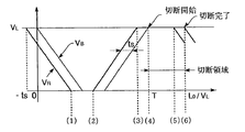
ここで、整定時間を補償した変速曲線のうち、図7に示す折線曲線について説明する。図において、VL はロータリーカッタの定速領域での速度を示す。定速領域では、ロータリーカッタの速度は、材料速度に同期する。時刻Tは、ロータリーカッタが定速になる時刻を示す。
【0041】
一般的には、ロータリーカッタは、機械の構成上、機械損失が少なく電動機にとってはイナーシャ負荷となっている。また、図1に示す駆動制御回路7は、高速の電流ループを有した制御回路を使用しているため、トルク応答は速度制御応答に比べ十分速いので、速度制御器16により得られる速度応答は1次遅れ応答となり、電動機を含めた機械定数をJ、速度制御ループゲインをKV 、時定数Tm =J/KV とするとカッタ速度VB は、
【0042】
【数4】
【0043】
となる。
【0044】
通常、図1に示した速度指令フィードフォワードゲインαを1、および加速度指令フィードフォワードゲインβを1とすることは過補償となり、図7に示すカッタ速度VB は、折線コーナの部分でオーバシュート(図示しない)を生じて精度不良を招くため、α<1およびβ<1とせざるを得ない。この場合は、オーバーシュートを抑制することが可能である反面、応答遅れが生じることになるが、本発明では整定時間を補償しているので、応答遅れを生じない。
【0045】
遅れのない応答について、図1の制御装置に基づいて説明をする。カッタ速度指令df(x)/dtに対して、カッタ速度VB は、
【0046】
【数5】
【0047】
となる。KP =α(1−α)/Tm である。
【0048】
ここで、補償器10による整定時間補償を
【0049】
【数6】
【0050】
とすると(但し、tS =(1−α)/KP )、カッタ速度指令は、
【0051】
【数7】
【0052】
となり、df(x)/dt=df(x)/dx・dx/dtと表せるので、
【0053】
【数8】
【0054】
となり、遅れのない応答が得られることになる。ここで、β=0とすると、
【0055】
【数9】
【0056】
となる。
【0057】
整定時間補償器10がない場合は、df(x)/dt=VL であるため、
【0058】
【数10】
【0059】
となり、カッタ速度VB が速度指令df(x)/dx・VL に対し整定時間tS 遅れた応答になる。このため、整定時間補償器10は、遅れ伝達特性の逆特性を与えることになるが、この実施例では、tS ・VL が材料移動距離にフィードフォワード補償されてdx/dt=(1+tS S)VL となり、図8の速度指令(1+tS S)・df(x)/dx・VL が与えられ、カッタ速度VB は、
【0060】
【数11】
【0061】
となり、図8に示すような遅れのない応答が得られる。なお、図7および図8において、(1)〜(5)は、同じタイミングを示している。
【0062】
次に、本発明の整定時間補償を適用できる変速曲線の他の例について説明する。ロータリーカッタ2が直線状に減速して速度が零になると直ちに直線状に加速を始める折線曲線について説明する。
【0063】
この折線曲線を求めると、カッタ速度指令df(x)/dtは、0≦t/T≦1/2の時、−(2/T)VL tとなり、1/2≦t/T≦1の時、VL {1−(2/T)(t−(T/2))}となる。ここで、VL T=2(L0 −B0 )であるから、位置指令f(x)は、
【0064】
【数12】
【0065】
となる。これにt=X/VL 、T=(L0 −Bw )/VL を代入すると、位置指令f(x)は、
【0066】
【数13】
【0067】
となる。但し、Bw は、図6に示すカッタの切断領域の周長を示す。
【0068】
上式において切断長L0 と切断領域の周長Bw との差分L0 −Bw は、材料移動距離xに対するカッタの変速領域を示し、あらかじめ切断長L0 に応じて演算されている。また、切断長L0 とカッタ周長B0 との差分L0 −B0 も、材料移動の見送り量として切断長L0 に応じて演算して与えられる。
【0069】
位置指令発生器12は、材料移動距離xに応じて上式(数13)に基づいて実時間で高速で位置指令f(x)を演算し出力する。この位置指令f(x)を微分器13で微分すれば、前述した折線曲線の速度指令が得られる。
【0070】
このような速度指令では、減速から加速に移るときに、衝撃が生じる。そこで、以下の例では、このような衝撃の生じない変速曲線の例を説明する。
【0071】
まず、正弦曲線の速度指令VR について説明する。このような速度指令は、次式で与えられる。
【0072】
【数14】
【0073】
従って、カッタ速度指令df(x)/dtは、変速領域の速度指令として次式によって与えられる。
【0074】
【数15】
【0075】
ここで、VL T=2(L0 −B0 )であるから、位置指令f(x)は、
【0076】
【数16】
【0077】
となる。この式にt=X/VL 、T=(L0 −Bw )/VL を代入すると位置指令f(x)は、
【0078】
【数17】
【0079】
となる。但し、Bw は、図6に示すカッタの切断領域の周長を示す。
【0080】
上式において切断長L0 と切断領域の周長Bw との差分L0 −Bw は、材料移動距離xに対するカッタの変速領域を示し、あらかじめ切断長L0 に応じて演算されている。また、切断長L0 とカッタ周長B0 との差分L0 −B0 も、材料移動の見送り量として切断長L0 に応じて演算して与えられる。
【0081】
位置指令発生器12は、材料移動距離xに応じて上式(数17)に基づいて実時間で位置指令f(x)を演算し出力する。この位置指令f(x)を微分器13で微分すれば、前述した正弦曲線の速度指令が得られる。
【0082】
以上の速度指令の加速度は、
【0083】
【数18】
【0084】
で表され、ピークの加速度は、
【0085】
【数19】
【0086】
で表され、加速度の実効値(RMS)は、
【0087】
【数20】
【0088】
で表され、半周期の加速度平均値は、
【0089】
【数21】
【0090】
で表される。
【0091】
比較のために、前述した減速から加速に移行する折線曲線について検討する。折線曲線の場合の加速度d2 f(x)/dt2 は、
【0092】
【数22】
【0093】
で表され、加速度の実効値(RMS)は、
【0094】
【数23】
【0095】
で表され、半周期の加速度平均値は、
【0096】
【数24】
【0097】
で表される。
【0098】
以上により、最大加速度変化率は、正弦曲線の場合、0から(−π2 /4)(VL /T)、(π2 /4)(VL /T)から0であり、従って、(π2 /4)(VL /T)となる。
【0099】
また、折線曲線の場合、最大加速度変化率は、(−2/T)VL から(2/T)VL であり、従って、(4/T)VL となる。
【0100】
従って、折線曲線の場合は、電動機が減速から加速に転ずる時に発生する衝撃的な力は大きな加速度変化比に依存するが、正弦曲線の場合は、加速度変化比が小さく、更に、電動機が減速から加速に転ずる時に発生する衝撃的な力はほぼ零となる。
【0101】
図9で説明したように、いずれの変速曲線も、ロータリーカッタの速度指令VR に対して、電動機の応答速度(カッタ速度VB )の遅れ分(tS )が生じるため、整定時間(tS )分補償する必要がある。
【0102】
従って、整定時間tS を位置指令発生器12の入力変数である材料移動距離に換算して補正することにより、カッタ速度指令VR を整定時間相当早く生成して与えて、応答速度(カッタ速度VB )を理想的な応答(tS =0)に一致させることができる。
【0103】
以上のような折線曲線および正弦曲線の速度指令について、本発明により整定時間補償を行って、整定時間tS だけ早く生成した速度指令VR を図2および図3に示す。また、正弦曲線の速度指令df(x)/dfを図4に示す。速度応答VB に応答遅れがないことがわかる。図5は、整定時間補償された位置指令f(x)を示す。
【0104】
変速曲線の他の例としては、3次曲線、5次曲線、サイクロイド曲線、変形台形曲線、変形正弦曲線がある。
【0105】
3次曲線における整定時間補償を行った速度指令VR を図10に、5次曲線における整定時間補償を行った速度指令VR を図11に、サイクロイド曲線における整定時間補償を行った速度指令VR を図12に、変形台形曲線における整定時間補償を行った速度指令VR を図13に、変形正弦曲線における整定時間補償を行った速度指令VR を図14に各々示す。
【0106】
以上のように整定時間補償を行って、応答速度(カッタ速度VB )を理想的な応答(tS =0)に一致させ、加速度の実効値を低減させることができる。
【0107】
例えば、変速曲線である各曲線に整定時間補償を実施した場合の加速度の実効値を求めると、折線曲線は(L0 −B0 )π2 /2(2)1/2 T2 、3次曲線は(L0 −B0 )2(3)1/2 /T2 、5次曲線は(L0 −B0 )(120/7)1/2 /T2 を、サイクロイド曲線は(L0 −B0 )(2)1/2 π/T2 、変形台形曲線は(L0 −B0 )4(3)1/2 π2 /{(π+2)T2 }を、変形正弦曲線(L0 −B0 )2(2)1/2 π2 /{(π+4)T2 }となる。
【0108】
この求めた整定時間補償した各曲線の加速度の実効値を各々1とし、整定時間を補償しない場合との比較を表1に示す。
【0109】
【表1】
【0110】
表1に示すように、走行する材料を切断するための整定時間を補償した変速曲線を有する最適な加減速レートにより電動機を制御し、ロータリーカッタの加減速の加速度(トルク)の実効値を低減させることにより、切断精度を落とすことなく整定時間領域を不要にし、かつ不必要な急加減速をなくし加速度(トルク)の実効値を低減させて生産性の向上を図ることができる。
【0111】
【発明の効果】
本発明によれば、加減速レートの整定時間を位置指令発生器の入力変数である材料の移動量に換算して整定時間分を補償することにより、カッタ速度指令を整定時間相当早く生成して与え、電動機の速度応答を理想的な応答に一致させ、また、折線状の速度指令に限定されることのない任意の速度指令を容易に生成できるので、各々の変速曲線の特徴に応じた効率的な切断ができるロータリーカッタの制御装置を実現できる。
【図面の簡単な説明】
【図1】本発明のロータリーカッタの制御構成を示すブロック図である。
【図2】折線曲線の速度指令特性を示す図である。
【図3】正弦曲線の速度指令特性を示す図である。
【図4】正弦曲線の速度指令特性を示す図である。
【図5】正弦曲線の位置特性を示す図である。
【図6】カッタの移動と材料との関係を示す図である。
【図7】折線曲線における整定時間補償を含む速度指令特性を示す図である。
【図8】折線曲線における整定時間補償を含む速度指令特性を示す図である。
【図9】従来における折線曲線の整定時間との慣例を示す図である。
【図10】3次曲線における整定時間補償との関連を示す図である。
【図11】5次曲線における整定時間補償との関連を示す図である。
【図12】サイクロイド曲線における整定時間補償との関連を示す図である。
【図13】変形台形曲線における整定時間補償との関連を示す図である。
【図14】変形正弦曲線における整定時間補償との関連を示す図である。
【図15】従来のロータリーカッタの制御ブロックを示す図である。
【符号の説明】
1 材料
2 ロータリーカッタ
3 主軸
4 減速ギヤー
5 電動機
6 パルスジェネレータ
7 駆動制御回路
8 測長ロール
9 パルスジェネレータ
10 整定時間補償器
11 積分器
12 位置指令発生器
13 微分器
14 積分器
15 位置制御器
16 速度制御器
17 速度指令フィードフォワード器(α)
18,19 微分器
20 加速度指令フィードフォワード器(β)
21 機械定数乗算器(J)
30 数値制御装置
31〜36 加算器
40 定尺切断回路部
41 切断寸法設定部
42 第1演算部
43 切断完了センサ
44 タイミング信号発生部
45 周長設定部
46 材料走行距離検出回路
47 モータ回転数検出回路
48 第2演算部
49,63 D/A変換器
50,64 関数発生器
51 F/V変換器
52 演算増幅器
53 切換回路
60 停止制御回路部
61 停止距離設定部
62 可逆カウンタ
65 比較部
70 切断完了センサ
80 数値制御装置Title: Control device for rotary cutter
[Claim of claim]
1. When controlling a motor that decelerates, accelerates, and drives at a constant speed a rotary cutter that cuts material following a traveling material, the response speed of the motor becomes a speed command due to a delay in control response. In the rotary cutter control device delayed with
In order to compensate for the settling time which is a delay of the response speed of the motor with respect to the speed command, a speed command is generated earlier by a time corresponding to the settling time, and the response speed of the motor according to the speed command is A control device of a rotary cutter characterized in that there is no delay.
2. The travel speed of the traveling material is detected, and the travel speed is integrated over time to determine the travel distance of the material, and a settling time compensation value is generated to compensate for the settling time from the detected travel speed. Material travel distance and the settling time compensation value are added, and this added value, material cutting length necessary for cutting the traveling material, circumferential length of the rotary cutter cutting area 2. The rotary cutter control device according to claim 1, wherein a position command is calculated from the values of ,, and a rotary cutter circumferential length, and the calculated position command is time-differentiated to generate the speed command.
3. When the speed command is a speed command for shifting from deceleration to acceleration in a shift range between constant speeds, the speed command is used to gradually reduce the speed when transferring the rotary cutter from speed reduction to acceleration. The control device according to claim 2, wherein the control device is a speed command that accelerates gradually after being driven.
4. When controlling a motor that decelerates, accelerates, and drives at a constant speed a rotary cutter that cuts material in accordance with the material that is traveling, the response speed of the motor becomes a speed command due to the delay of the control response. In the control device, which delays the settling time with respect to
A pulse generator for detecting the moving speed of the traveling material;
An integrator for time-integrating the moving velocity to obtain the moving distance of the material;
A settling time compensator for generating a settling time compensation value that compensates for the settling time from the detected moving speed;
An adder for adding the moving distance of the material and the settling time compensation value;
Position command to calculate the position command from the added value and the values of material cutting length which is conditions to cut the traveling material, circumference of rotary cutter cutting area, and rotary cutter circumference. Generator,
A differentiator that temporally differentiates the calculated position command to generate the speed command;
A rotary cutter control device comprising:
5. When the speed command is a speed command to shift from deceleration to acceleration in a shift range between constant speeds, the speed command gradually decelerates when shifting the rotary cutter from deceleration to acceleration. The control device according to claim 4, wherein the control device is a speed command that accelerates gradually after being driven.
Detailed Description of the Invention
[0001]
Field of the Invention
The present invention cuts a material such as a steel plate, aluminum plate, paper, cardboard, etc., which is continuously fed at high speed, while a cutting blade that rotates by numerical control follows the material, and between cutting and cutting by numerical control The present invention relates to a control device of a rotary cutter that changes the rotation of a cutter to match a cutting length to a set length.
[0002]
[Prior Art]
FIG. 15 shows a block diagram of a control device of a conventional rotary cutter for cutting materials such as steel plates, aluminum plates, paper, and cardboard which are continuously fed at high speed, and FIG. 9 shows a conventional speed command characteristic diagram.
[0003]
As shown in FIG. 15, there are a pair of rotary cutters 2 having blades on the circumferential surface in the axial direction, and a reduction gear 4 is attached to a main shaft 3 of the rotary cutter 2 and an electric motor 5 for driving the rotary cutters 2 is provided. It is combined. The motor 5 is provided with a pulse generator (PG) 6 for detecting the rotational speed of the motor and the rotational angle of the motor, that is, the rotational angle of the main shaft 3 of the rotary cutter 2.
[0004]
On the other hand, a length measuring wheel 8 for detecting the amount of movement of the traveling material 1 is provided, and a pulse generator (PG) 9 for detecting the amount of movement is provided on the axis of the length measuring wheel 8 . Furthermore, a cutting completion position sensor 70 is provided which detects the cutting completion position every time the material 1 being traveled is cut by the rotary cutter 2. As disclosed in Japanese Patent Publication No. 61-33679, the numerical control device 30 of the rotary cutter 2 is roughly composed of the fixed length cutting circuit unit 40, the stop control circuit unit 60, and the comparing unit 53. It is done.
[0005]
The fixed-size cutting circuit unit 40 is a circuit for accurately cutting the material 1 to a set predetermined length, and the cutting dimension setting unit 41, the first calculation unit 42, the cutting completion sensor 43, and the timing signal generating unit 44, perimeter setting unit 45, material travel distance detection circuit 46, motor rotation number detection circuit 47, second operation unit 48, D / A converter 49, function generator 50, F / V converter 51, operational amplifier 52 It consists of
[0006]
In the fixed length cutting circuit section, the cutting completion position is detected by the cutting completion position sensor 70 each time the material 1 being traveled by the rotary cutter 2 is cut, and the cutting length L is generated each time the cutting completion position signal is generated. 0 And circumference B of the rotary cutter 2 0 Difference L with L = L 0 -B 0 The number of pulses corresponding to {circumflex over (d)} is read into the calculation unit 48 of the fixed-size cutting circuit unit 40.
[0007]
The number of pulses Φ generated by the pulse generator 9 as the material 1 travels a (Ie, the amount of movement of the material) and Φ generated from the pulse generator 6 as the rotary cutter 2 rotates. b Difference with (the amount of rotation of the rotary cutter 2) Φ a -Φ b Ie R = L 0 -B 0 -(Φ a -Φ b Compensation voltage V corresponding to the difference R c = F (R) and a voltage obtained by frequency-voltage (F / V) conversion of the output of the pulse generator (PG) 9, that is, a voltage V representing the amount of movement of the material 1 a Difference V with 0 = V a -V c , V 0 Only when it is> 0, it is supplied to the drive control circuit 7 of the motor 5 as a speed command.
[0008]
The stop control circuit unit 60 includes a stop distance setting unit 61, a reversible counter 62, a D / A converter 63, a function generator 64, and a comparison unit 65.
[0009]
In such a stop control circuit unit, whenever the blade of the rotary cutter 2 passes the cutting completion position sensor 70 and the cutting completion signal is generated, the reversible counter 62 sets the stopping distance of the blade of the rotary cutter 2 set in advance. Pulse number パ ル ス corresponding to s Number of pulses 表 す which represents the amount of rotation of the rotary cutter 2 while reading b The D / A converter 64 subtracts the DC voltage V b Convert to
[0010]
The comparison unit 53 outputs the output voltage V of the comparison unit 65 of the stop control circuit unit 60. 1 And the speed command voltage V output from the operational amplifier 52 of the fixed length cutting circuit 40 0 And the higher one, the final command voltage V 2 As the drive control circuit 7.
[0011]
In the numerical control device 30 as described above, the speed voltage V of the material 1 is a Against compensation voltage V c To compensate for the speed of the material 1 according to the difference R, and at the time of cutting, the difference R becomes zero and V c = 0, ie, V c = V a Synchronize the speed of the rotary cutter 2 with the speed of the material 1 as a , Φ b When either one leads or lags the other, digital servo control is performed to perform acceleration / deceleration control of the motor so that the difference becomes zero, so that material 1 can be accurately cut to a predetermined length. can do.
[0012]
[Problems to be solved by the invention]
However, the above-described conventional rotary cutter control device has the following problems. That is, as shown in FIG. 9, the speed command (broken line curve) V of the acceleration / deceleration rate R Response V of the motor to B Is delayed due to the delay in control response. This delay time t S Indicated. Thus, when the cutter speed is synchronized to the material speed, t S It will be delayed by a minute. There is a problem that an error occurs in the cutting length when there is such a delay in control response. Hereinafter, in this specification, the delay time t S Is called settling time.
[0013]
Also, in the conventional rotary cutter control device, acceleration and deceleration are performed linearly, and the acceleration rate during acceleration and the deceleration rate during deceleration are determined by the gain of the D / A converter. Become.
[0014]
When the acceleration / deceleration rate is a fixed value, there is a problem that efficient cutting can not be performed because the acceleration / deceleration rate is constant regardless of the cutting length and the traveling speed of the material.
[0015]
Furthermore, if the acceleration and deceleration are linear, an impulsive force is generated when transitioning from deceleration to acceleration, resulting in failures such as gear noise, wear and breakage.
[0016]
In order to solve such a problem, the inventor has devised a control device that makes the speed command in the shift region between constant speed regions be a characteristic such as a sine curve or a quadratic curve instead of a broken curve. did. Hereinafter, in the present specification, a curve representing a speed command in the shift region will be referred to as a shift curve.
[0017]
Delays in control response are common problems, whether the shift curve is a curve or a sine curve, quadratic curve, etc. as described above.
[0018]
The object of the present invention is to solve the above-mentioned problems, and generate and give cutter speed commands as fast as settling time, match the speed response of the motor to the ideal response, and It is an object of the present invention to provide a control device of a rotary cutter that can perform efficient cutting in accordance with the characteristics of the speed change curve.
[0019]
[Means for Solving the Problems]
According to the present invention, when controlling a motor that decelerates, accelerates, and drives at a constant speed a rotary cutter that cuts material following a traveling material, the response speed of the motor responds to the speed command due to a delay in control response. In order to compensate for the settling time which is the delay of the response speed of the motor with respect to the speed command, the speed command is generated earlier by a time corresponding to the settling time, and the motor according to this speed command There is no delay in the settling time in the response speed of.
[0020]
The present invention further detects the moving speed of the traveling material, integrates the moving speed with respect to time to obtain the moving distance of the material, and compensates for the settling time compensating the settling time from the detected moving speed. The moving distance of the material and the settling time compensation value are added, and the added value and the material cutting length necessary for cutting the traveling material, the circumference of the rotary cutter cutting area A position command is calculated from the length and the value of the rotary cutter circumferential length, and the calculated position command is time-differentiated to generate the speed command.
[0021]
Further, according to the present invention, in the case where the speed command is a speed command for shifting from deceleration to acceleration in a shift region between constant speeds, the speed command is gradually transferred when the rotary cutter is shifted from deceleration to acceleration. It is characterized in that it is a speed command which accelerates gradually after being decelerated.
[0022]
BEST MODE FOR CARRYING OUT THE INVENTION
FIG. 1 is a block diagram showing a configuration of a control device of a rotary cutter according to the present invention. As shown in FIG. 1, there are a pair of rotary cutters 2 having a blade on the circumferential surface in the axial direction, and a motor 5 for driving the cutter 2 is coupled to the main shaft 3 of the cutter by a gear 4. The motor 5 is provided with a pulse generator (PG) 6 for detecting the rotation angle of the motor, that is, the rotation angle of the cutter 2.
[0023]
On the other hand, a length measuring roll 8 for detecting the speed of the traveling material 1 is provided, and the axis of the length measuring roll 8 is provided with a pulse generator (PG) 9.
[0024]
In order to detect the speed of the traveling material 1, the measuring roller 8 performs pressure contact, that is, nips, with the two upper and lower measuring rollers 8 on both sides of the traveling material 1, and measurement occurs as the material travels By the rotation of the long roll 8, a pulse is generated from the pulse generator 9 for each unit rotation, and by counting the pulses, the speed V of the continuously traveling material L Is detected.
[0025]
Next, the numerical control device 80 will be described. The numerical controller 80 includes a settling time compensator 10, an integrator 11, a position command generator 12, a differentiator 13, an integrator 14, a position controller 15, a speed controller 16, differentiators 18 and 19, and a multiplier 17. , 20, a mechanical constant multiplier 21, and adders 31 to 37.
[0026]
Material velocity V generated from pulse generator 9 as material 1 travels L Are simultaneously input to the settling time compensator 10 (to be described in detail later) of the numerical controller 80 and the integrator 11. V input to the settling time compensator 10 L Is the delay of the response speed of the motor (t S Is output by the adder 31 together with the output of the integrator 11, and the value obtained by the addition is input to the position command generator 12 as the material movement distance x. The position command generator 12 provides a position command f (x) as a function of the material movement distance x. The differentiator 13 outputs a cutter speed command df (x) / dt by time-differentiating the position command f (x).
[0027]
On the other hand, the moving speed V of the rotary cutter 2 is determined from the pulse generated from the pulse generator 6 as the rotary cutter 2 rotates. B Is obtained.
[0028]
With the adder 32, the speed command df (x) / df and the material speed V L And cutter speed V B And are input to the integrator 14 and output as the position deviation e. This position deviation e is
[0029]
[Equation 1]
[0030]
Given by The position deviation e is input to the position controller 15 and the compensation velocity V is c Is output as
[0031]
On the other hand, the cutter speed command df (x) / dt is multiplied by the feedforward constant α in the multiplier 17 to obtain the material speed V in the adder 36 as a speed command feedforward signal. L Together. Furthermore, the compensation speed V is C And the adder 34 further adds the cutter speed V B And the velocity deviation .DELTA.V is determined. The velocity deviation ΔV is
[0032]
[Equation 2]
[0033]
Given by
[0034]
The speed deviation ΔV is input to the speed controller 16 and the correction torque command τ A Is output as
[0035]
Meanwhile, the material velocity V L The material acceleration dV by time differentiation with the differentiator 18 L Get / dt. The cutter acceleration command d is obtained by differentiating the cutter speed command df (x) / dt with the differentiator 19 in time. 2 f (x) / dt 2 Get This cutter acceleration command d 2 f (x) / dt 2 Is multiplied by the feedforward β constant by the multiplier 20 to obtain an acceleration command feedforward signal. This acceleration command feed forward signal and material acceleration dV L Adder 37 adds / dt to machine constant multiplier 21 and multiplies by machine constant J to obtain reference torque command τ B Output as
[0036]
Thus, the reference torque command τ B Is obtained by multiplying the mechanical constant (J) by changing the acceleration, which is the change rate, by multiplying the mechanical inertia and feedforward compensating it as the motor torque command. This is to improve the followability to the changing speed command of the cutter, which is the inertia load.
[0037]
This reference torque command τ B And correction torque command τ A Is added by the adder 35, and the motor torque command τ is R ,
[0038]
[Equation 3]
[0039]
And gives a command to the motor 5 through the drive control circuit 7.
[0040]
Here, among the shift curves in which the settling time is compensated, the broken line curve shown in FIG. 7 will be described. In the figure, V L Indicates the velocity in the constant velocity region of the rotary cutter. In the constant velocity region, the velocity of the rotary cutter is synchronized to the material velocity. The time T indicates the time when the rotary cutter is at a constant speed.
[0041]
In general, the rotary cutter has a small mechanical loss and is an inertia load for the motor due to the construction of the machine. Further, since the drive control circuit 7 shown in FIG. 1 uses a control circuit having a high speed current loop, the torque response is sufficiently faster than the speed control response, so the speed response obtained by the speed controller 16 is First-order delay response, J is mechanical constant including motor, K is speed control loop gain V , Time constant T m = J / K V And cutter speed V B Is
[0042]
[Equation 4]
[0043]
It becomes.
[0044]
Generally, setting the speed command feed forward gain α to 1 and the acceleration command feed forward gain β to 1 shown in FIG. 1 results in overcompensation, and the cutter speed V shown in FIG. B Since an overshoot (not shown) occurs at a corner portion of the broken line to cause accuracy deterioration, it is necessary to set α <1 and β <1. In this case, although it is possible to suppress overshoot, response delay will occur, but since the settling time is compensated in the present invention, response delay does not occur.
[0045]
The response without delay will be described based on the control device of FIG. Cutter speed V for cutter speed command df (x) / dt B Is
[0046]
[Equation 5]
[0047]
It becomes. K P = Α (1-α) / T m It is.
[0048]
Here, the settling time compensation by the compensator 10
[0049]
[Equation 6]
[0050]
If (assuming that t S = (1-α) / K P ), Cutter speed command,
[0051]
[Equation 7]
[0052]
And df (x) / dt = df (x) / dx · dx / dt.
[0053]
[Equation 8]
[0054]
And a response without delay will be obtained. Here, assuming that β = 0,
[0055]
[Equation 9]
[0056]
It becomes.
[0057]
If there is no settling time compensator 10, then df (x) / dt = V L Because
[0058]
[Equation 10]
[0059]
And the cutter speed V B Is the speed command df (x) / dx · V L Against settling time t S It is a delayed response. For this reason, the settling time compensator 10 will provide the inverse characteristic of the delay transfer characteristic, but in this embodiment t S ・ V L Is feedforward compensated to the material movement distance, dx / dt = (1 + t S S) V L And the speed command (1 + t in FIG. S S) · df (x) / dx · V L Is given, cutter speed V B Is
[0060]
[Equation 11]
[0061]
Thus, a response without delay as shown in FIG. 8 is obtained. In FIGS. 7 and 8, (1) to (5) indicate the same timing.
[0062]
Next, another example of the shift curve to which the settling time compensation of the present invention can be applied will be described. A broken line curve will be described in which acceleration is linearly started as soon as the rotary cutter 2 linearly decelerates and the speed becomes zero.
[0063]
The cutter speed command df (x) / dt is − (2 / T) V when 0 ≦ t / T ≦ 1/2 when this broken line curve is determined. L t, and when 1/2 ≦ t / T ≦ 1, V L It becomes {1- (2 / T) (t- (T / 2))}. Where V L T = 2 (L 0 -B 0 The position command f (x) is
[0064]
[Equation 12]
[0065]
It becomes. T = X / V L , T = (L 0 -B w ) / V L Substituting, position command f (x),
[0066]
[Equation 13]
[0067]
It becomes. However, B w These show the perimeter of the cutting area | region of the cutter shown in FIG.
[0068]
Cutting length L in the above equation 0 And perimeter B of the cutting area w Difference L with 0 -B w Indicates the gear shift area of the cutter with respect to the material movement distance x, and the cutting length L in advance 0 It is calculated according to. Also, cutting length L 0 And cutter circumference B 0 Difference L with 0 -B 0 Also, the cutting length L as the feed-through amount of material movement 0 It is calculated and given according to.
[0069]
The position command generator 12 calculates and outputs the position command f (x) at high speed in real time based on the above equation (Equation 13) according to the material movement distance x. If the position command f (x) is differentiated by the differentiator 13, the above-mentioned speed command of the broken line curve can be obtained.
[0070]
In such a speed command, an impact occurs when moving from deceleration to acceleration. Therefore, in the following example, an example of a shift curve without such an impact will be described.
[0071]
First, the sinusoidal velocity command V R Will be explained. Such speed command is given by the following equation.
[0072]
[Equation 14]
[0073]
Therefore, the cutter speed command df (x) / dt is given by the following equation as a speed command for the shift region.
[0074]
[Equation 15]
[0075]
Where V L T = 2 (L 0 -B 0 The position command f (x) is
[0076]
[Equation 16]
[0077]
It becomes. In this equation t = X / V L , T = (L 0 -B w ) / V L Substituting the position command f (x) gives
[0078]
[Equation 17]
[0079]
It becomes. However, B w These show the perimeter of the cutting area | region of the cutter shown in FIG.
[0080]
Cutting length L in the above equation 0 And perimeter B of the cutting area w Difference L with 0 -B w Indicates the gear shift area of the cutter with respect to the material movement distance x, and the cutting length L in advance 0 It is calculated according to. Also, cutting length L 0 And cutter circumference B 0 Difference L with 0 -B 0 Also, the cutting length L as the feed-through amount of material movement 0 It is calculated and given according to.
[0081]
The position command generator 12 calculates and outputs the position command f (x) in real time based on the equation (17) according to the material movement distance x. If the position command f (x) is differentiated by the differentiator 13, the above-described velocity command of a sine curve can be obtained.
[0082]
The acceleration of the speed command above is
[0083]
[Equation 18]
[0084]
And the peak acceleration is
[0085]
[Equation 19]
[0086]
And the root mean square of acceleration (RMS) is
[0087]
[Equation 20]
[0088]
The half cycle acceleration average value is
[0089]
[Equation 21]
[0090]
Is represented by
[0091]
For comparison, we will consider the above-mentioned curve that transitions from deceleration to acceleration. Acceleration d in the case of a broken curve 2 f (x) / dt 2 Is
[0092]
[Equation 22]
[0093]
And the root mean square of acceleration (RMS) is
[0094]
[Equation 23]
[0095]
The half cycle acceleration average value is
[0096]
[Equation 24]
[0097]
Is represented by
[0098]
From the above, in the case of a sinusoidal curve, the maximum rate of change of acceleration is from 0 to (-π 2 / 4) (V L / T), (π) 2 / 4) (V L / T) to 0, so (π 2 / 4) (V L / T).
[0099]
Also, in the case of a broken curve, the maximum acceleration change rate is (−2 / T) V L From (2 / T) V L And therefore (4 / T) V L It becomes.
[0100]
Therefore, in the case of a broken curve, the impulsive force generated when the motor turns from deceleration to acceleration depends on a large acceleration change ratio, but in the case of a sinusoidal curve, the acceleration change ratio is small. The impulsive force generated when turning to acceleration is almost zero.
[0101]
As described in FIG. 9, the speed command V of the rotary cutter is also used for any of the shift curves. R , The response speed of the motor (cutter speed V B ) Of the delay (t S Settling time (t) S ) Need to compensate for the minute.
[0102]
Therefore, the settling time t S The cutter speed command V is corrected by converting it into a material movement distance which is an input variable of the position command generator R The response time (cutter speed V B An ideal response (t) S = 0) can be matched.
[0103]
The settling time compensation is performed according to the present invention for the velocity command of the above-described broken curve and sinusoidal curve, and the settling time t is S Speed command V generated earlier R Is shown in FIG. 2 and FIG. Further, a sinusoidal speed command df (x) / df is shown in FIG. Speed response V B It can be seen that there is no response delay. FIG. 5 shows the settling time compensated position command f (x).
[0104]
Other examples of shift curves include cubic curves, quintic curves, cycloid curves, deformed trapezoidal curves, and deformed sine curves.
[0105]
Speed command V with settling time compensation in cubic curve R Figure 10 shows the speed command V with settling time compensation in the 5th order curve R Figure 11 shows the speed command V with settling time compensation in the cycloid curve. R Figure 12 shows the velocity command V with settling time compensation for the deformed trapezoidal curve. R Figure 13 shows the speed command V with settling time compensation for the deformed sine curve R Are respectively shown in FIG.
[0106]
The settling time compensation is performed as described above, and the response speed (cutter speed V B An ideal response (t) S (0) to reduce the effective value of acceleration.
[0107]
For example, when the effective value of acceleration when settling time compensation is performed on each curve that is a shift curve is determined, the broken line curve 0 -B 0 ) Π 2 / 2 (2) 1/2 T 2 , Cubic curve (L 0 -B 0 ) 2 (3) 1/2 / T 2 , The fifth order curve (L 0 -B 0 ) (120/7) 1/2 / T 2 , The cycloid curve (L 0 -B 0 ) (2) 1/2 π / T 2 , The modified trapezoidal curve (L 0 -B 0 ) 4 (3) 1/2 π 2 / {(Π + 2) T 2 }, The modified sine curve (L 0 -B 0 ) 2 (2) 1/2 π 2 / {(Π + 4) T 2 }.
[0108]
The effective values of the accelerations of the respective settling time-compensated curves thus determined are respectively set to 1, and a comparison with the case where the settling time is not compensated is shown in Table 1.
[0109]
[Table 1]
[0110]
As shown in Table 1, the motor is controlled by the optimum acceleration / deceleration rate with a shift curve that compensates for the settling time to cut the traveling material, and the effective value of acceleration (torque) of acceleration / deceleration of the rotary cutter is reduced. By doing this, it is possible to eliminate the need for the settling time region without lowering the cutting accuracy, eliminate unnecessary rapid acceleration and deceleration, reduce the effective value of the acceleration (torque), and improve the productivity.
[0111]
【Effect of the invention】
According to the present invention, the cutter speed command is generated as early as the settling time by converting the settling time of the acceleration / deceleration rate into the movement amount of the material which is the input variable of the position command generator and compensating for the settling time. To match the speed response of the motor to the ideal response and to easily generate any speed command not limited to a linear speed command, so the efficiency according to the characteristics of each shift curve It is possible to realize a control device of a rotary cutter that can perform various cutting.
Brief Description of the Drawings
FIG. 1 is a block diagram showing a control configuration of a rotary cutter of the present invention.
FIG. 2 is a diagram showing speed command characteristics of a broken curve.
FIG. 3 is a diagram showing speed command characteristics of a sinusoidal curve.
FIG. 4 is a diagram showing speed command characteristics of a sinusoidal curve.
FIG. 5 is a diagram showing position characteristics of a sinusoidal curve.
FIG. 6 is a view showing the relationship between the movement of the cutter and the material.
FIG. 7 is a diagram showing speed command characteristics including settling time compensation in a broken curve.
FIG. 8 is a diagram showing speed command characteristics including settling time compensation in a broken curve.
FIG. 9 is a diagram showing a conventional practice of settling time of a broken line curve.
FIG. 10 is a diagram showing the relationship of settling time compensation in a cubic curve.
FIG. 11 is a diagram showing the relation to settling time compensation in a fifth-order curve.
FIG. 12 is a diagram showing the relation to settling time compensation in a cycloid curve.
FIG. 13 is a diagram showing the relationship between settling time compensation in a deformed trapezoidal curve and FIG.
FIG. 14 is a diagram showing the relation to settling time compensation in a modified sine curve.
FIG. 15 is a view showing a control block of a conventional rotary cutter.
[Description of the code]
1 material
2 Rotary cutter
3 spindle
4 Reduction gear
5 Motor
6 pulse generator
7 Drive control circuit
8 Measuring roll
9 pulse generator
10 Settling time compensator
11 Integrator
12 Position command generator
13 Differentiator
14 integrator
15 Position controller
16 speed controller
17 Speed command feed forwarder (α)
18, 19 Differentiator
20 Acceleration command feed forwarder (β)
21 Mechanical constant multiplier (J)
30 Numerical Control Unit
31 to 36 adder
40 Fixed cutting circuit
41 Cutting dimension setting unit
42 1st operation unit
43 Disconnection complete sensor
44 Timing signal generator
45 lap setting section
46 material travel distance detection circuit
47 Motor revolution detection circuit
48 Second operation unit
49, 63 D / A converter
50, 64 function generator
51 F / V converter
52 Operational Amplifier
53 switching circuit
60 Stop control circuit
61 Stop distance setting unit
62 reversible counter
65 Comparison section
70 Disconnection complete sensor
80 Numerical Control Unit