FR2820507A1 - DISCHARGE INTO A PASSIVE RADAR RECEIVER OF OFDM SIGNALS - Google Patents
DISCHARGE INTO A PASSIVE RADAR RECEIVER OF OFDM SIGNALS Download PDFInfo
- Publication number
- FR2820507A1 FR2820507A1 FR0101695A FR0101695A FR2820507A1 FR 2820507 A1 FR2820507 A1 FR 2820507A1 FR 0101695 A FR0101695 A FR 0101695A FR 0101695 A FR0101695 A FR 0101695A FR 2820507 A1 FR2820507 A1 FR 2820507A1
- Authority
- FR
- France
- Prior art keywords
- signals
- signal
- spectral lines
- symbol
- radar receiver
- Prior art date
- Legal status (The legal status is an assumption and is not a legal conclusion. Google has not performed a legal analysis and makes no representation as to the accuracy of the status listed.)
- Granted
Links
Classifications
-
- G—PHYSICS
- G01—MEASURING; TESTING
- G01S—RADIO DIRECTION-FINDING; RADIO NAVIGATION; DETERMINING DISTANCE OR VELOCITY BY USE OF RADIO WAVES; LOCATING OR PRESENCE-DETECTING BY USE OF THE REFLECTION OR RERADIATION OF RADIO WAVES; ANALOGOUS ARRANGEMENTS USING OTHER WAVES
- G01S13/00—Systems using the reflection or reradiation of radio waves, e.g. radar systems; Analogous systems using reflection or reradiation of waves whose nature or wavelength is irrelevant or unspecified
- G01S13/003—Bistatic radar systems; Multistatic radar systems
-
- G—PHYSICS
- G01—MEASURING; TESTING
- G01S—RADIO DIRECTION-FINDING; RADIO NAVIGATION; DETERMINING DISTANCE OR VELOCITY BY USE OF RADIO WAVES; LOCATING OR PRESENCE-DETECTING BY USE OF THE REFLECTION OR RERADIATION OF RADIO WAVES; ANALOGOUS ARRANGEMENTS USING OTHER WAVES
- G01S13/00—Systems using the reflection or reradiation of radio waves, e.g. radar systems; Analogous systems using reflection or reradiation of waves whose nature or wavelength is irrelevant or unspecified
- G01S13/02—Systems using reflection of radio waves, e.g. primary radar systems; Analogous systems
- G01S13/50—Systems of measurement based on relative movement of target
- G01S13/52—Discriminating between fixed and moving objects or between objects moving at different speeds
- G01S13/522—Discriminating between fixed and moving objects or between objects moving at different speeds using transmissions of interrupted pulse modulated waves
- G01S13/524—Discriminating between fixed and moving objects or between objects moving at different speeds using transmissions of interrupted pulse modulated waves based upon the phase or frequency shift resulting from movement of objects, with reference to the transmitted signals, e.g. coherent MTi
-
- G—PHYSICS
- G01—MEASURING; TESTING
- G01S—RADIO DIRECTION-FINDING; RADIO NAVIGATION; DETERMINING DISTANCE OR VELOCITY BY USE OF RADIO WAVES; LOCATING OR PRESENCE-DETECTING BY USE OF THE REFLECTION OR RERADIATION OF RADIO WAVES; ANALOGOUS ARRANGEMENTS USING OTHER WAVES
- G01S7/00—Details of systems according to groups G01S13/00, G01S15/00, G01S17/00
- G01S7/02—Details of systems according to groups G01S13/00, G01S15/00, G01S17/00 of systems according to group G01S13/00
- G01S7/41—Details of systems according to groups G01S13/00, G01S15/00, G01S17/00 of systems according to group G01S13/00 using analysis of echo signal for target characterisation; Target signature; Target cross-section
- G01S7/414—Discriminating targets with respect to background clutter
Landscapes
- Engineering & Computer Science (AREA)
- Radar, Positioning & Navigation (AREA)
- Remote Sensing (AREA)
- Computer Networks & Wireless Communication (AREA)
- Physics & Mathematics (AREA)
- General Physics & Mathematics (AREA)
- Radar Systems Or Details Thereof (AREA)
Abstract
Description
<Desc/Clms Page number 1> <Desc / Clms Page number 1>
Réjection de fouillis dans un récepteur radar passif de signaux OFDM
La présente invention concerne un récepteur radar passif recevant un signal radioélectrique composé de trames de symboles émis chacun sur des porteuses orthogonales codées. Clutter rejection in a passive radar receiver of OFDM signals
The present invention relates to a passive radar receiver receiving a radio signal composed of frames of symbols each transmitted on coded orthogonal carriers.
Dans le domaine radar, il est généralement difficile, voire impossible, d'atteindre les performances limites atteignables en terme de détection pour une cible mobile. En effet, ces performances, qui sont fixées par le rapport signal à bruit thermique en sortie d'un filtre adapté dans le récepteur radar, sont généralement limitées, en pratique, non pas par le niveau de bruit thermique mais par le niveau associé au fouillis en sortie du filtre adapté. Le terme fouillis est, ici, à prendre au sens large puisqu'il désigne l'ensemble des trajets à Doppler nul. Par exemple, pour un radar bistatique dont l'émetteur et le récepteur sont distants, le fouillis désigne l'ensemble des trajets suivants : trajet directement issu de l'émetteur ainsi que chaque trajet reçu après réflexion sur un obstacle fixe. In the radar field, it is generally difficult, if not impossible, to achieve the limit performance achievable in terms of detection for a moving target. Indeed, these performances, which are fixed by the signal to thermal noise ratio at the output of a matched filter in the radar receiver, are generally limited, in practice, not by the level of thermal noise but by the level associated with the clutter. at the outlet of the matched filter. The term clutter is, here, to be taken in the broad sense since it designates all the paths with zero Doppler. For example, for a bistatic radar from which the transmitter and the receiver are distant, the clutter designates the set of the following paths: path directly coming from the transmitter as well as each path received after reflection on a fixed obstacle.
Divers procédés de réjection de ces signaux indésirables sont connus mais présentent des inconvénients non négligeables. Par exemple, les procédés de réjection adaptatives basés sur l'utilisation d'une matrice de covariance des signaux reçus par un réseau de capteurs présentent les limitations suivantes :
Ils n'éliminent qu'un nombre limité de signaux d'interférence décorrélés, caractérisés par leur Various methods of rejecting these undesirable signals are known but have non-negligible drawbacks. For example, the adaptive rejection methods based on the use of a covariance matrix of the signals received by a sensor network have the following limitations:
They only eliminate a limited number of decorrelated interference signals, characterized by their
<Desc/Clms Page number 2><Desc / Clms Page number 2>
direction. En conséquence, ces procédés ne sont pas optimaux dans le cadre de la lutte contre le fouillis lorsque celui-ci est riche en multitrajets de retards différents. direction. Consequently, these methods are not optimal in the context of the fight against clutter when the latter is rich in multipaths of different delays.
- Ils entraînent la création d'axes aveugles, liés aux signaux rejetés, suivant lesquels il devient impossible de détecter une cible. - They lead to the creation of blind axes, linked to the rejected signals, according to which it becomes impossible to detect a target.
- Ils ne rejettent que des signaux dont le rapport signal à bruit est positif en sortie de compression angulaire. Cette réjection est limitative lorsqu'elle est effectuée en tête de traitement radar, c'est-àdire avant la compression distance-Doppler. - They only reject signals with a positive signal-to-noise ratio at the angular compression output. This rejection is limiting when it is carried out at the head of the radar processing, that is to say before the distance-Doppler compression.
L'invention est plus particulièrement dirigée vers la réjection de l'ensemble des trajets à Doppler nul dans le fouillis capté par un récepteur radar passif de signaux particuliers de type OFDM (Orthogonal Frequency Division Multiplex). Les signaux OFDM sont caractérisés par l'émission simultanée d'un grand nombre de sous-porteuses orthogonales codées à plusieurs états de phase, c'est-à-dire par un spectre de raies orthogonales au sens de la transformée de Fourier sur une durée finie T, équidistantes en 1/T. The invention is more particularly directed towards the rejection of all the zero-Doppler paths in the clutter picked up by a passive radar receiver of particular signals of the OFDM (Orthogonal Frequency Division Multiplex) type. OFDM signals are characterized by the simultaneous emission of a large number of orthogonal subcarriers encoded in several phase states, that is to say by a spectrum of orthogonal lines in the sense of the Fourier transform over a period finite T, equidistant in 1 / T.
Selon la demande de brevet FR 2776438, un radar bistatique traite des signaux de radiocommunication numériques au format COFDM (Coded OFDM) dans le cadre de radiodiffusion et de télédiffusion de programmes selon les normes européennes DAB (Digital Audio Broadcasting) et DVB (Digital Video Broadcasting). According to patent application FR 2776438, a bistatic radar processes digital radiocommunication signals in COFDM (Coded OFDM) format in the context of radio and television broadcasting of programs according to European standards DAB (Digital Audio Broadcasting) and DVB (Digital Video Broadcasting) ).
Ces signaux émis ainsi par des émetteurs d'opportunité pour des applications de récepteur radar passif assurent une utilisation optimale du spectre émis, d'une manière similaire à un bruit These signals thus transmitted by transmitters of opportunity for passive radar receiver applications ensure optimal use of the transmitted spectrum, in a manner similar to noise.
<Desc/Clms Page number 3><Desc / Clms Page number 3>
blanc, et sont résistants aux multitrajets et interférences. white, and are resistant to multipath and interference.
Selon ce brevet, le récepteur radar comprend plusieurs antennes de réception pour détecter ces signaux. Le traitement radar repose sur la corrélation Doppler-distance des signaux reçus avec une référence temporelle de signal émis. La référence temporelle est obtenue en décodant les signaux enregistrés conformément aux opérations effectuées en radio-télécommunications. According to this patent, the radar receiver comprises several reception antennas for detecting these signals. The radar processing is based on the Doppler-distance correlation of the signals received with a temporal reference of the transmitted signal. The time reference is obtained by decoding the signals recorded in accordance with the operations carried out in radio-telecommunications.
Cependant, étant donnée la nature bistatique du système radar, la puissance du signal de trajet direct est élevée par rapport à celle du signal utile réfléchi par une cible. Le trajet direct devrait être rejeté avant d'effectuer la corrélation Dopplerdistance. L'énergie contenue dans les lobes secondaires distance-Doppler du trajet direct est généralement nettement supérieure au niveau de bruit thermique, si bien que des cibles situées à proximité du trajet direct sont difficilement détectables. However, due to the bistatic nature of the radar system, the power of the direct path signal is high relative to that of the wanted signal reflected from a target. The direct path should be rejected before performing the Dopplerdistance correlation. The energy contained in the distance-Doppler sidelobes of the direct path is generally much greater than the thermal noise level, so targets near the direct path are difficult to detect.
L'invention a pour objectif de réduire, voire supprimer la contribution du trajet direct et plus généralement de signaux parasites à effet Doppler nul dans le traitement des signaux reçus avant la corrélation Doppler-distance. The object of the invention is to reduce or even eliminate the contribution of the direct path and more generally of parasitic signals with zero Doppler effect in the processing of the signals received before the Doppler-distance correlation.
Pour atteindre cet objectif, un récepteur radar selon l'invention traitant un signal radioélectrique reçu à travers un canal de propagation et composé de trames de symboles émis chacun sur des porteuses orthogonales codées, comprenant un moyen de mise en forme pour mettre le signal reçu sous forme d'un signal numérique de symboles et un moyen de To achieve this objective, a radar receiver according to the invention processing a radio signal received through a propagation channel and composed of frames of symbols each transmitted on encoded orthogonal carriers, comprising a formatting means for putting the received signal under form of a digital signal of symbols and a means of
<Desc/Clms Page number 4><Desc / Clms Page number 4>
corrélation Doppler-distance pour discriminer des cibles mobiles, est caractérisé en ce qu'il comprend un moyen de filtrage pour éliminer dans le signal de symboles au moins des signaux parasites à effet Doppler nul afin d'appliquer un signal filtré contenant essentiellement des signaux rétrodiffusés par des cibles au moyen de corrélation. Doppler-distance correlation for discriminating moving targets, is characterized in that it comprises filtering means for eliminating in the symbol signal at least parasitic signals with zero Doppler effect in order to apply a filtered signal essentially containing backscattered signals by targets by means of correlation.
Selon une première réalisation, notamment pour un radar comportant une seule voie de réception, le moyen de filtrage comprend un moyen pour produire des raies spectrales du signal de symboles correspondant aux porteuses orthogonales, un moyen pour détecter les signaux parasites à effet Doppler nul par estimation de coefficients de la fonction de transfert du canal de propagation respectivement dans les raies spectrales, un moyen pour soustraire les raies spectrales des signaux parasites à effet Doppler nul déduits des coefficients de la fonction de transfert estimée aux raies spectrales de signal de symboles, et un moyen pour synthétiser les raies spectrales produites par le moyen pour soustraire en le signal filtré. Cette première réalisation élimine les signaux parasites à effet Doppler nul, c'est-àdire essentiellement les signaux dûs aux trajets directs et multiples depuis un émetteur donné. According to a first embodiment, in particular for a radar comprising a single reception channel, the filtering means comprises a means for producing spectral lines of the symbol signal corresponding to the orthogonal carriers, a means for detecting the parasitic signals with zero Doppler effect by estimation of coefficients of the transfer function of the propagation channel respectively in the spectral lines, a means for subtracting the spectral lines from the parasitic signals with zero Doppler effect deduced from the coefficients of the transfer function estimated at the spectral lines of the signal of symbols, and a means for synthesizing the spectral lines produced by the means for subtracting into the filtered signal. This first embodiment eliminates the parasitic signals with zero Doppler effect, that is to say essentially the signals due to the direct and multiple paths from a given transmitter.
Afin de mieux caractériser la fonction de transfert du canal de propagation indépendamment de signaux rétrodiffusés sur des cibles, les raies spectrales des signaux parasites sont estimées pour chaque symbole et moyennées sur chaque trame dans le moyen pour détecter, avant d'être soustraites aux raies spectrales du signal de symboles. Dans cette première réalisation est alors prévu un moyen pour estimer une réplique de signal émis en fonction des In order to better characterize the transfer function of the propagation channel independently of signals backscattered onto targets, the spectral lines of the parasitic signals are estimated for each symbol and averaged over each frame in the means for detecting, before being subtracted from the spectral lines. signal symbols. In this first embodiment, a means is then provided for estimating a replica of the transmitted signal as a function of the
<Desc/Clms Page number 5><Desc / Clms Page number 5>
raies spectrales des signaux parasites à effet Doppler nul, la réplique estimée étant corrélée au signal filtré dans le moyen de corrélation Dopplerdistance. spectral lines of the parasitic signals with zero Doppler effect, the estimated replica being correlated with the signal filtered in the Dopplerdistance correlation means.
Selon une deuxième réalisation pour un radar comportant plusieurs voies de réception, dans lequel le moyen de mise en forme comprend plusieurs moyens de réception et met en forme plusieurs signaux reçus par les moyens de réception sous forme de signaux numériques de symboles, le moyen de filtrage comprend un moyen pour produire des groupes de raies spectrales des signaux de symboles correspondant respectivement aux porteuses orthogonales, un moyen pour estimer des matrices de covariance dépendant chacune de produits des raies spectrales deux à deux dans un groupe relatif à une porteuse respective, un moyen pour déduire des matrices inverses des matrices de covariance, un moyen pour filtrer les groupes de raies spectrales relatifs respectivement aux porteuses en multipliant les groupes de raies par les matrices inverses respectives afin de produire des groupes filtrés de raies spectrales, et un moyen pour synthétiser les groupes filtrés de raies spectrales en des signaux de symboles filtrés contenant essentiellement des signaux rétrodiffusés par des cibles appliqués au moyen de corrélation. Cette deuxième réalisation élimine également des signaux brouilleurs autres que des signaux corrélés codés de type COFDM. According to a second embodiment for a radar comprising several reception channels, in which the formatting means comprises several reception means and forms several signals received by the reception means in the form of digital symbol signals, the filtering means comprises means for producing groups of spectral lines of the symbol signals corresponding respectively to the orthogonal carriers, means for estimating covariance matrices each depending on products of the two-by-two spectral lines in a group relating to a respective carrier, means for derive from the inverse matrices of the covariance matrices, a means for filtering the groups of spectral lines relative respectively to the carriers by multiplying the groups of lines by the respective inverse matrices in order to produce filtered groups of spectral lines, and a means for synthesizing the groups filtered from spectral lines into wire symbol signals Very containing essentially signals backscattered by targets applied by means of correlation. This second embodiment also eliminates interfering signals other than coded correlated signals of COFDM type.
Afin de mieux caractériser la fonction de transfert du canal de propagation, les produits de raies spectrales dont dépendent les matrices de covariances dépendent de raies spectrales de symboles et sont moyennés sur chaque trame. In order to better characterize the transfer function of the propagation channel, the products of spectral lines on which the covariance matrices depend depend on spectral lines of symbols and are averaged over each frame.
<Desc/Clms Page number 6> <Desc / Clms Page number 6>
Dans la deuxième réalisation est en outre prévu un moyen pour estimer une réplique de signal émis en fonction des raies spectrales de l'un des signaux de symbole par estimation de coefficients de la fonction de transfert du canal de propagation dans les signaux parasites à effet Doppler nul, la réplique estimée étant corrélée aux signaux de symboles filtrés dans le moyen de corrélation. In the second embodiment, a means is also provided for estimating a replica of the transmitted signal as a function of the spectral lines of one of the symbol signals by estimating the coefficients of the transfer function of the propagation channel in the parasitic Doppler signals. zero, the estimated replica being correlated to the symbol signals filtered in the correlation means.
D'autres caractéristiques et avantages de la présente invention apparaîtront plus clairement à la lecture de la description suivante de plusieurs réalisations préférées de l'invention en référence aux dessins annexés correspondants dans lesquels : la figure 1 est un diagramme temporel de symboles successifs dans un signal COFDM émis ;

- la figure 2 est un diagramme temporel d'une trame de signal COFDM ; la figure 3 est un diagramme de trajets direct, multiples et réfléchi par une cible entre un émetteur et un récepteur ; - la figure 4 montre les sorties des différents contributeurs (trajet direct, multi-trajets, cible, bruit) en sortie de corrélateur ; - la figure 5 est un bloc-diagramme schématique d'un récepteur radar avec une antenne selon une première réalisation de l'invention ; - la figure 6 est un bloc-diagramme schématique d'un récepteur radar avec plusieurs antennes selon une deuxième réalisation de l'invention ; - la figure 7 est un diagramme de rayonnement du réseau d'antennes du récepteur radar selon la deuxième réalisation. Other characteristics and advantages of the present invention will emerge more clearly on reading the following description of several preferred embodiments of the invention with reference to the corresponding appended drawings in which: FIG. 1 is a temporal diagram of successive symbols in a signal COFDM issued;
FIG. 2 is a timing diagram of a COFDM signal frame; FIG. 3 is a direct, multiple, and reflected path diagram from a target between a transmitter and a receiver; FIG. 4 shows the outputs of the various contributors (direct path, multiple paths, target, noise) at the correlator output; FIG. 5 is a schematic block diagram of a radar receiver with an antenna according to a first embodiment of the invention; FIG. 6 is a schematic block diagram of a radar receiver with several antennas according to a second embodiment of the invention; FIG. 7 is a radiation diagram of the antenna array of the radar receiver according to the second embodiment.
<Desc/Clms Page number 7> <Desc / Clms Page number 7>
Les caractéristiques principales de signaux COFDM en radiocommunications sont rappelées ci-après, en référence à la figure 1. The main characteristics of COFDM signals in radiocommunications are recalled below, with reference to FIG. 1.
Ces signaux en bande de base sont émis par période
![]()
1 de symbole Tg. Un message contenu dans chacun de ces symboles émis est porté par un nombre important de sinusoïdes émises simultanément. Ces sinusoïdes constituent des sous-porteuses, appelées ci-après

"porteuses"par souci de simplification, et sont codées en phase. Les fréquences de porteuses fI à fK sont équidistantes de 1/TS. Chaque symbole émis Si résulte de la somme suivante de porteuses pendant la durée T'S (T'S > TS) :

où j désigne l'imaginaire pure racine de-1 (j2 =-1), et t la variable temps.
![]()
![]()
1 of symbol Tg. A message contained in each of these symbols transmitted is carried by a large number of sinusoids transmitted simultaneously. These sinusoids constitute sub-carriers, hereinafter called
"carriers" for the sake of simplicity, and are phase coded. The carrier frequencies fI to fK are equidistant from 1 / TS. Each symbol emitted Si results from the following sum of carriers during the duration T'S (T'S> TS):
where j denotes the pure imaginary root of -1 (j2 = -1), and t the time variable.
![]()
Les porteuses aux fréquences fk = kiTs avec 1 k K sont donc orthogonales sur la durée Tg. A = Tc ; - TS désigne l'intervalle de garde. The carriers at frequencies fk = kiTs with 1 k K are therefore orthogonal over the duration Tg. A = Tc; - TS designates the guard interval.
Sur une période d'analyse TS, les signaux COFDM constituent ainsi un signal de bande KITS composé d'un spectre de K raies équidistantes du pas de fréquence liTS et chacune de largeur 1/TS. Les porteuses sont modulées individuellement à l'aide, par exemple, d'un code à quatre états de phase exprimés par les coefficients complexes Ck, i appartenant à l'alphabet (l+j, 1-j, -1+j, -1-j). Over an analysis period TS, the COFDM signals thus constitute a band signal KITS composed of a spectrum of K lines equidistant from the frequency step liTS and each of width 1 / TS. The carriers are individually modulated using, for example, a code with four phase states expressed by the complex coefficients Ck, i belonging to the alphabet (l + j, 1-j, -1 + j, - 1-j).
En pratique, un message de données peut n'occuper que quelques fréquences fk sur quelques périodes de symbole TS dans le multiplex temporel et fréquentiel de K fréquences et de I intervalles de temps. In practice, a data message can occupy only a few frequencies fk over a few symbol periods TS in the time and frequency multiplex of K frequencies and I time slots.
<Desc/Clms Page number 8> <Desc / Clms Page number 8>
A l'émission, les symboles sont organisés en trame. Chaque trame montrée à la figure 2 comprend I symboles SI à SI. Le premier symbole SI de la trame est un symbole"nul"ne portant aucune information et est constitué de la fréquence porteuse de modulation Fo du signal émis. Le symbole SI sert de synchronisation de trame, c'est-à-dire de référence temporelle. Le deuxième symbole S2 de la trame sert notamment à l'apprentissage du canal de propagation dans le récepteur radar et contient les K porteuses ou sinusoïdes prises aux fréquences fI à fK ayant des phases prédéterminées dans l'émetteur. Ces K porteuses dans le symbole SI sont utilisées dans le récepteur radar, pour estimer le signal émis, chaque porteuse fk servant de référence en fréquence et phase. Grâce aux deux premiers symboles peuvent être
![]()
ainsi acquis au moins les paramètres d'émission Fo, TS et fI à fK. Les autres symboles S3 à SI sont destinés à supporter un ou plusieurs messages de données occupant partiellement ou non chaque symbole. On transmission, the symbols are organized in frames. Each frame shown in FIG. 2 comprises I symbols SI to SI. The first symbol SI of the frame is a “null” symbol carrying no information and consists of the modulation carrier frequency Fo of the transmitted signal. The symbol SI serves as frame synchronization, that is to say as a time reference. The second symbol S2 of the frame is used in particular for learning the propagation channel in the radar receiver and contains the K carriers or sinusoids taken at the frequencies fI to fK having predetermined phases in the transmitter. These K carriers in the symbol SI are used in the radar receiver to estimate the transmitted signal, each carrier fk serving as a frequency and phase reference. Thanks to the first two symbols can be
![]()
thus acquired at least the emission parameters Fo, TS and fI to fK. The other symbols S3 to SI are intended to support one or more data messages partially or not partially occupying each symbol.
A la réception, en radiocommunication, les symboles sont récupérés à l'aide d'une analyse fréquentielle des signaux COFDM reçus sur la durée Tg. Les fréquences émises étant orthogonales au sens d'une transformée de Fourier FFT, chacune des porteuses est démodulée afin de restituer l'information. On reception, in radiocommunication, the symbols are recovered using a frequency analysis of the COFDM signals received over the duration Tg. The frequencies transmitted being orthogonal in the sense of a Fourier transform FFT, each of the carriers is demodulated in order to to return the information.
En pratique, l'orthogonalité des fréquences émises est dégradée par les interférences suivantes : - interférences intersymboles intraporteuses : superposition de signaux codés différemment ou durée d'analyse TS non adaptée au code ;

interférences intersymbole interporteuses : signaux non orthogonaux sur la durée d'analyse Tg ; In practice, the orthogonality of the frequencies emitted is degraded by the following interferences: - intra-carrier intersymbol interference: superposition of signals coded differently or TS analysis time not suited to the code;
intersymbol inter-carrier interferences: non-orthogonal signals over the analysis time Tg;
<Desc/Clms Page number 9><Desc / Clms Page number 9>
- interférences intrasymboles intraporteuses : superposition de signaux codés différemment ; - interférences intrasymboles interporteuses : signaux non stationnaires. - intra-carrier intrasymbol interference: superposition of signals coded differently; - inter-carrier intrasymbol interference: non-stationary signals.
Ces interférences sont liées aux trajets multiples dans le canal de propagation entre l'émetteur et le récepteur.

L'adjonction de l'intervalle de garde A à chaque , période de symbole TS permet de s'affranchir de période de symbole Ts toutes les interférences, lorsque l'intervalle de garde A est supérieur à l'étalement temporel du canal de propagation dû aux trajets multiples : il existe alors pour chaque durée TS une plage de longueur TS dans laquelle tous les signaux reçus issus des multitrajets sont codés de façon identique. The addition of the guard interval A to each symbol period TS makes it possible to dispense with the symbol period Ts all interference, when the guard interval A is greater than the temporal spread of the propagation channel due. multiple paths: there is then for each duration TS a range of length TS in which all the signals received from the multiple paths are coded identically.
Le traitement des signaux reçus comprenant une corrélation Doppler-distance, la fonction d'ambiguïté des signaux COFDM et notamment ses lobes secondaires doivent être étudiés. Les lobes secondaires de la fonction d'ambiguïté associée à la forme d'onde COFDM sont relativement uniformes dans le plan distanceDoppler, et leur niveau par rapport au lobe principal est de-10. logio (I. K). Les lobes secondaires sont moins élevés au pied du pic principal. The processing of the received signals comprising a Doppler-distance correlation, the ambiguity function of the COFDM signals and in particular its secondary lobes must be studied. The side lobes of the ambiguity function associated with the COFDM waveform are relatively uniform in the distanceDoppler plane, and their level relative to the main lobe is -10. logio (I. K). The sidelobes are lower at the foot of the main peak.
L'étude classique du bilan radar montre qu'en général l'énergie contenue dans les lobes secondaires associés au trajet direct est prépondérante vis-à-vis du bruit thermique. The classic study of the radar balance shows that in general the energy contained in the secondary lobes associated with the direct path is preponderant with respect to thermal noise.
A titre d'exemple, on considère un radar bistatique montré à la figure 3 avec un émetteur EM de puissance électromagnétique rayonnée PeGe = 1000 W, un gain d'antenne de récepteur RE, Gr = 10 dB, une longueur d'onde À = 1 m correspondant à la fréquence Fo = 300 MHz, une distance émetteur-récepteur d = 40 km, des distances émetteur-cible EM-CB et distances As an example, we consider a bistatic radar shown in Figure 3 with an EM transmitter of radiated electromagnetic power PeGe = 1000 W, a receiver antenna gain RE, Gr = 10 dB, a wavelength λ = 1 m corresponding to the frequency Fo = 300 MHz, a transmitter-receiver distance d = 40 km, transmitter-target distances EM-CB and distances
<Desc/Clms Page number 10><Desc / Clms Page number 10>
cible-récepteur CB-RE égales à 40 km, un facteur de bruit F = 6 dB, une surface équivalente radar SER = 0 dB, 1 = 100 symboles de durée TS = 1 ms et un intervalle de garde de 250 s pour une durée de trame de 125 ms, et K = 1500 porteuses pour une largeur de bande de B = 1,5 MHz. target-receiver CB-RE equal to 40 km, a noise factor F = 6 dB, a radar equivalent area SER = 0 dB, 1 = 100 symbols of duration TS = 1 ms and a guard interval of 250 s for a duration frame rate of 125 ms, and K = 1500 carriers for a bandwidth of B = 1.5 MHz.
Le bilan de liaison entre l'émetteur EM et le récepteur RE est montré à la figure 4. The link budget between the EM transmitter and the RE receiver is shown in Figure 4.
L'énergie contenue dans les lobes secondaires attachés au trajet direct et au fouillis (clutter) dû aux trajets multiples est prépondérante par rapport au bruit thermique. Le niveau d'énergie des lobes du trajet direct se trouve à 186-135 = 51 dB au-dessus du niveau présumé de la cible qui présente un rapport signal à bruit thermique de 198-186 = 12 dB. The energy contained in the secondary lobes attached to the direct path and to the clutter due to the multiple paths is preponderant in relation to the thermal noise. The energy level of the direct path lobes is 186-135 = 51 dB above the presumed level of the target which has a thermal signal-to-noise ratio of 198-186 = 12 dB.
L'invention vise donc à rejeter efficacement le trajet direct et le fouillis dans un signal reçu à large bande avant la corrélation Doppler-distance afin de détecter des cibles mobiles. The invention therefore aims to efficiently reject the direct path and clutter in a wideband received signal before the Doppler-distance correlation in order to detect moving targets.
En référence maintenant à la figure 5, un récepteur radar passif REa pour signaux OFDM selon l'invention comprend un circuit de mise en forme de signal reçu 1, un circuit de filtrage de signaux corrélés 2, un détecteur de signaux corrélés 3, un circuit de détermination de cibles 4 et un estimateur de réplique de signal émis 5. Referring now to FIG. 5, a passive radar receiver REa for OFDM signals according to the invention comprises a received signal shaping circuit 1, a correlated signal filtering circuit 2, a correlated signal detector 3, a circuit for determining targets 4 and an emitted signal replica estimator 5.
Le circuit de mise en forme de signal reçu 1 comprend classiquement en entrée une antenne 11 et un étage de réception à radiofréquence OFDM 12 analogues à ceux pour recevoir des signaux de radiodiffusion et télédiffusion OFDM. Après transposition en fréquence, l'étage de réception 12 convertit numériquement le signal radioélectrique reçu suivant X (t) en bande de The received signal shaping circuit 1 conventionally comprises at input an antenna 11 and an OFDM radiofrequency reception stage 12 similar to those for receiving OFDM radio and television broadcasting signals. After frequency transposition, the reception stage 12 digitally converts the radio signal received along X (t) into a band.
<Desc/Clms Page number 11><Desc / Clms Page number 11>
base et l'applique à un circuit d'estimation de paramètres d'émission et de canal 13 :

X (t) = TD (t) + SC (t) + B (t), k=K 2j7tkt/T où pour chaque symbole émis L Ck e S, en k=l
![]()
faisant abstraction de l'indice i du symbole Si :

X (t) = TD (t) + SC (t) + B (t), k = K 2j7tkt / T where for each symbol emitted L Ck e S, in k = l
![]()
disregarding the index i of the symbol Si:
![]()
désigne un signal OFDM reçu provenant à la fois d'au moins un émetteur EM ou éventuellement de plusieurs émetteurs OFDM selon des trajets directs et des trajets multiples dûs à des réflecteurs fixes RF et correspondant au fouillis (clutter), comme illustré à la figure 3 ; Hk désigne un coefficient complexe correspondant à la fonction de transfert du canal de

propagation EM-REa relativement à ces trajets pour la raie fk ; le signal TD (t) est constitué par la superposition de signaux parasites à effet Doppler nul dûs aux trajets directs et multiples ; ces signaux parasites sont appelés"signaux corrélés" ;

désigne un signal reçu OFDM issu de la rétrodiffusion de signaux émis OFDM par au moins une cible mobile CB et donc affectés d'un effet Doppler non nul ; il constitue le signal utile à extraire dont la puissance est très faible comparativement à celle des signaux corrélés TD (t) ; hc est la fonction de transfert à bande étroite de la cible CB, T dénote la ![]()
designates an OFDM signal received from both at least one EM transmitter or possibly from several OFDM transmitters along direct paths and multiple paths due to fixed RF reflectors and corresponding to clutter, as illustrated in Figure 3 ; Hk denotes a complex coefficient corresponding to the transfer function of the channel of
EM-REa propagation relative to these paths for the fk line; the TD (t) signal is formed by the superposition of parasitic signals with zero Doppler effect due to the direct and multiple paths; these parasitic signals are called "correlated signals";
designates an OFDM received signal resulting from the backscattering of signals transmitted OFDM by at least one mobile target CB and therefore affected by a non-zero Doppler effect; it constitutes the useful signal to be extracted, the power of which is very low compared to that of the correlated signals TD (t); hc is the narrowband transfer function of the target CB, T denotes the
<Desc/Clms Page number 12><Desc / Clms Page number 12>
différence de marche entre le trajet direct et le trajet réfléchi par la cible, et v est la fréquence Doppler de la cible ; - B (t) désigne des signaux reçus dans la bande passante utile, appelés brouilleurs, autres que les signaux OFDM corrélés, tels que des signaux d'interférence et de bruit thermique. path difference between the direct path and the path reflected by the target, and v is the Doppler frequency of the target; - B (t) designates signals received in the useful bandwidth, called jammers, other than the correlated OFDM signals, such as interference and thermal noise signals.
Le circuit 13 estime les paramètres du signal émis, tels que la fréquence de porteuse Fo et la durée de symbole TS en fonction d'une analyse des deux premiers symboles Si et S2 d'une trame (figure 2) afin de constituer une référence temporelle. Circuit 13 estimates the parameters of the transmitted signal, such as the carrier frequency Fo and the symbol duration TS as a function of an analysis of the first two symbols Si and S2 of a frame (FIG. 2) in order to constitute a time reference .
Connaissant la période TS du signal émis et la durée durée TS de chaque symbole, la longueur temporelle du canal est déduite du processus de synchronisation de la référence temporelle précédente, en analysant le signal reçu à l'intérieur de chaque intervalle de garde A qui est supérieur à la longueur temporelle de canal. Knowing the TS period of the transmitted signal and the duration TS duration of each symbol, the temporal length of the channel is deduced from the synchronization process of the preceding temporal reference, by analyzing the signal received within each guard interval A which is greater than the temporal channel length.
Puis, le signal reçu est tronqué périodiquement dans un circuit de troncature 14. La partie stationnaire des symboles reçus de durée TS est récupérée en retirant la portion de signal reçu dans l'intervalle de garde A de chaque période T's et particulièrement en retirant la longueur de canal déduite dans chaque période. Then, the received signal is periodically truncated in a truncation circuit 14. The stationary part of the received symbols of duration TS is recovered by removing the portion of signal received in the guard interval A of each period T's and particularly by removing the length. channel deducted in each period.
Chaque partie de durée TS dans le signal reçu numérique en bande de base est ensuite appliquée à un analyseur de Fourier 21 en entrée du circuit de filtrage 2. L'analyseur produit les composantes réelle et imaginaire du signal reçu pour chaque durée TS par transformée de Hilbert et les analyse par transformée de Fourier rapide FFT pour fournir le spectre fréquentiel de chaque symbole Si délivré par Each part of duration TS in the digital received signal in baseband is then applied to a Fourier analyzer 21 at the input of the filtering circuit 2. The analyzer produces the real and imaginary components of the received signal for each duration TS by transform of Hilbert and analyzes them by fast Fourier transform FFT to provide the frequency spectrum of each symbol Si delivered by
<Desc/Clms Page number 13> <Desc / Clms Page number 13>

le circuit de troncature 14. Les K raies spectrales SPI à SPK du symbole relatives aux fréquences fI à fK sont appliquées au détecteur 3 et à des premières entrées d'un soustracteur 22. L'information portée par chaque raie spectrale SPk relative à une fréquence émise indépendamment des autres fréquences est liée d'une part au codage de la raie spectrale correspondante et d'autre part à la fonction de transfert Hk du canal de propagation.
the truncation circuit 14. The K spectral lines SPI to SPK of the symbol relating to the frequencies fI to fK are applied to the detector 3 and to the first inputs of a subtractor 22. The information carried by each spectral line SPk relating to a frequency transmitted independently of the other frequencies is linked on the one hand to the coding of the corresponding spectral line and on the other hand to the transfer function Hk of the propagation channel.
Pendant une phase d'apprentissage récurrente à chaque trame de symboles, le détecteur 3 déduit des raies spectrales de chaque symbole de la trame, les raies spectrales d'un signal de référence SR (t) tel que :
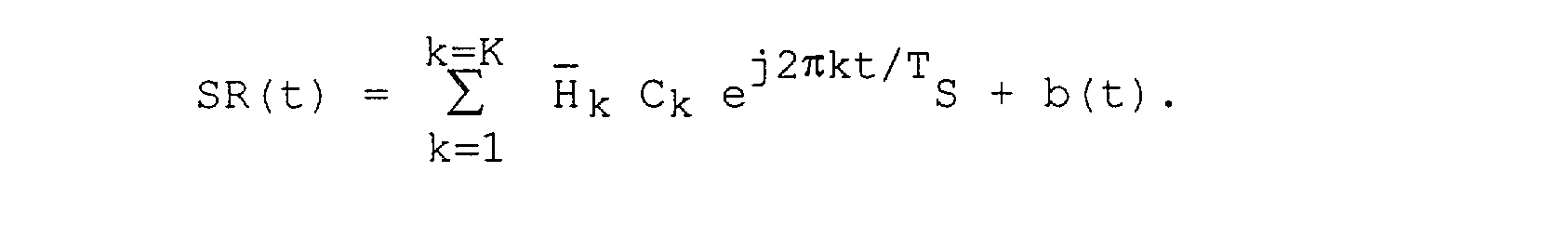
où Hk est la moyenne des 1-1 coefficients de la fonction de transfert de canal de propagation pour la raie SPk pendant les symboles S2 à SI de la trame, soit quasiment lhkl = lhkl, ce qui améliore l'estimation de la fonction de transfert du canal, en la rendant moins dépendante de variations d'amplitude et de phase instantanées. Ce moyennage permet de négliger le signal rétrodiffusé de cible SC (t) et donc de caractériser le canal de propagation et les signaux corrélés. Le signal de bruit b (t) désigne une moyenne de brouilleurs reçus pendant la trame, composés essentiellement d'un bruit thermique de variance inférieure à celle des brouilleurs B (t). During a learning phase which recurs at each frame of symbols, the detector 3 deduces from the spectral lines of each symbol of the frame, the spectral lines of a reference signal SR (t) such as:
where Hk is the average of the 1-1 coefficients of the propagation channel transfer function for the line SPk during the symbols S2 to SI of the frame, i.e. almost lhkl = lhkl, which improves the estimation of the transfer function of the channel, making it less dependent on instantaneous amplitude and phase variations. This averaging makes it possible to neglect the backscattered target signal SC (t) and therefore to characterize the propagation channel and the correlated signals. The noise signal b (t) designates an average of jammers received during the frame, composed essentially of a thermal noise of lower variance than that of the jammers B (t).
Après avoir mémorisé les coefficients de fonction de transfert Hl à HK moyennés pendant une trame, le détecteur 3 applique les raies spectrales des signaux corrélés à effet Doppler nul moyennées After having memorized the transfer function coefficients H1 to HK averaged during a frame, the detector 3 applies the spectral lines of the correlated signals with zero Doppler effect averaged.
<Desc/Clms Page number 14> <Desc / Clms Page number 14>
![]()
sur une trame, c'est-à-dire les raies moyennées du signal SR (t) dépendant des coefficients Hl à HK à K deuxièmes entrées du soustracteur 22. Le soustracteur soustrait les raies du signal SR (t) aux raies spectrales de signal reçu SPI à SPK, relativement à chaque symbole S2 à SI de la trame. Le soustracteur 22 produit alors des raies spectrales d'un signal filtré : X' (t) = SC (t) + B (t)-b (t) dans lesquelles a été éliminée la contribution des signaux corrélés à effet Doppler nul dûs au trajet direct et aux trajets multiples par la soustraction Hk-Hk = 0 pour chaque fréquence respective fk. ![]()
on a frame, that is to say the averaged lines of the signal SR (t) depending on the coefficients H1 to HK to K second inputs of the subtracter 22. The subtractor subtracts the lines of the signal SR (t) from the spectral lines of signal received SPI to SPK, relative to each symbol S2 to SI of the frame. The subtracter 22 then produces spectral lines of a filtered signal: X '(t) = SC (t) + B (t) -b (t) in which the contribution of the correlated signals with zero Doppler effect due to the direct and multipath path by subtracting Hk-Hk = 0 for each respective frequency fk.
Dans le circuit de filtrage 2, les raies du signal X' (t) sont synthétisées par transformée de Fourier rapide inverse FFT dans un synthétiseur 23 qui restitue le train de symboles du signal numérique X' (t) comprenant principalement le signal de rétrodiffusion de cible SC (t). Ce signal X' (t) est appliqué au circuit de discrimination de cibles 4. In the filtering circuit 2, the lines of the signal X '(t) are synthesized by inverse fast Fourier transform FFT in a synthesizer 23 which restores the symbol train of the digital signal X' (t) mainly comprising the backscattering signal of target SC (t). This signal X '(t) is applied to the target discrimination circuit 4.
Parallèlement, l'estimateur de réplique de signal émis 5 reçoit les coefficients Hk = Hk de la fonction de transfert de canal estimée par le détecteur 3 et les densités spectrales du signal de référence SR (t) pour estimer une réplique Re (t) du signal émis :

De manière analogue à une voie Doppler du récepteur radar selon la demande de brevet français FR 2776438, le circuit de discrimination de cibles 4 comprend un corrélateur Doppler-distance 41. Des voies Doppler dans le corrélateur 41 sont affectées In a manner analogous to a Doppler channel of the radar receiver according to French patent application FR 2776438, the target discrimination circuit 4 comprises a Doppler-distance correlator 41. Doppler channels in the correlator 41 are affected.
<Desc/Clms Page number 15><Desc / Clms Page number 15>
d'un écart de fréquence prédéterminé les unes par rapport aux autres dû à l'effet Doppler. Les voies Doppler constituent plusieurs cases vitesse du signal filtré X' (t) par des changements de fréquence et sont corrélées chacune, pour chaque porteuse fI à fK, à la réplique de signal émis Re (T). Après sommation, un circuit de focalisation angulaire 42 détermine des cases angulaires positionnant des cibles mobiles. a predetermined frequency deviation from each other due to the Doppler effect. The Doppler channels constitute several speed bins of the filtered signal X '(t) by changes in frequency and are each correlated, for each carrier fI to fK, to the emitted signal replica Re (T). After summation, an angular focusing circuit 42 determines angular boxes positioning moving targets.
Enfin, un circuit de Traitement de Fausse Alarme Constante (TFAC) 43 extrait des"plots"relatifs à des données de positionnement et vitesse sur des cibles mobiles recherchées. Finally, a Constant False Alarm Processing (TFAC) circuit 43 extracts "plots" relating to positioning and speed data on sought-after moving targets.
Bien que cette première réalisation ait été décrite pour un radar bistatique, celle-ci peut être appliquée à un radar monostatique. Elle peut être également mise en oeuvre dans un radar avec plusieurs antennes de réception et donc plusieurs filtrages par soustraction de raies spectrales dépendant des coefficients de fonction de transfert Hl à Hk pour les K raies spectrales relatives à chaque antenne de réception dans le circuit de filtrage 2 qui produit autant de signaux filtrés X' (t) que d'antennes pour être traités en parallèle dans des voies Doppler du circuit 4, comme dans le circuit 4b montré à la figure 6. Although this first embodiment has been described for a bistatic radar, it can be applied to a monostatic radar. It can also be implemented in a radar with several reception antennas and therefore several filterings by subtraction of spectral lines depending on the transfer function coefficients H1 to Hk for the K spectral lines relating to each reception antenna in the filtering circuit. 2 which produces as many filtered signals X '(t) as there are antennas to be processed in parallel in Doppler channels of circuit 4, as in circuit 4b shown in FIG. 6.
Dans la réalisation décrite ci-dessus selon la figure 5, le signal reçu X (t) était traité pour y éliminer la contribution du trajet direct et des trajets multiples entre au moins un émetteur COFDM EM et le récepteur REa. Toutefois, les brouilleurs, tels que signaux d'interférence et bruit thermique dans la bande de fréquence utile, n'étaient pas éliminés dans le signal X' (t) traité par le corrélateur 41. In the embodiment described above according to FIG. 5, the received signal X (t) was processed to eliminate therein the contribution of the direct path and of the multiple paths between at least one COFDM EM transmitter and the receiver REa. However, the jammers, such as interference signals and thermal noise in the useful frequency band, were not eliminated in the signal X '(t) processed by the correlator 41.
<Desc/Clms Page number 16> <Desc / Clms Page number 16>
Selon une deuxième réalisation montrée à la figure 6, le récepteur Radar REb vise à éliminer tous les signaux corrélés parasites et brouilleurs. According to a second embodiment shown in FIG. 6, the Radar REb receiver aims to eliminate all the parasitic and interfering correlated signals.
Le récepteur REb comprend plusieurs antennes de réception 111 à 11N reliées respectivement à plusieurs récepteurs 121 à 12N pour signaux COFDM avec N 2. Le récepteur radar REb présente une structure analogue à celui REa montré à la figure 5, mais avec N voies de réception parallèles entre les circuits 13b, 14b, 2b et 4b respectivement associées aux antennes 111 à 11N. The REb receiver comprises several reception antennas 111 to 11N connected respectively to several receivers 121 to 12N for COFDM signals with N 2. The REb radar receiver has a structure similar to that REa shown in FIG. 5, but with N parallel reception channels. between the circuits 13b, 14b, 2b and 4b respectively associated with the antennas 111 to 11N.
Le détecteur 3 et l'estimateur de réplique 5 ne sont pas modifiés. Le détecteur 3 produit un signal de référence SR (t) relatif à l'une des antennes 111 à 11N, par exemple en fonction des K raies spectrales S ? n à SPK1 de la première voie liée à l'antenne 111, qui sont délivrées par l'analyseur de spectre 21b qui analyse N trains de symbole reçus fournis par le circuit de troncature 14b. L'estimateur 5 produit une réplique de signal émis à bande étroite Re (t) appliqués à N corrélateurs Doppler-distance 41b dans le circuit de discrimination de cibles 4. Detector 3 and the replica estimator 5 are not modified. The detector 3 produces a reference signal SR (t) relating to one of the antennas 111 to 11N, for example as a function of the K spectral lines S? n to SPK1 of the first channel linked to the antenna 111, which are delivered by the spectrum analyzer 21b which analyzes N received symbol trains supplied by the truncation circuit 14b. The estimator 5 produces a replica of the transmitted narrowband signal Re (t) applied to N Doppler-distance correlators 41b in the target discrimination circuit 4.
Comparativement au récepteur REa, le récepteur REb en diffère essentiellement par le circuit de filtrage à bandes étroites 2b qui supprime les signaux parasites à effet Doppler nul TD (t) et les brouilleurs B (t). Compared to the receiver REa, the receiver REb differs from it essentially by the narrow-band filtering circuit 2b which eliminates the parasitic signals with zero Doppler effect TD (t) and the jammers B (t).
Le circuit de filtrage 2b comprend, entre l'analyseur de spectre 21b produisant en parallèle K raies spectrales pour chaque symbole des signaux

reçus Xl (t) à XN (t) et le synthétiseur de Fourier 23b t t fournissant N signaux filtrés Xi (t) à XN (t) aux corrélateurs 41b, successivement un module de calcul de matrices de covariance 24b, un module de calcul de The filtering circuit 2b comprises, between the spectrum analyzer 21b producing in parallel K spectral lines for each symbol of the signals
received Xl (t) to XN (t) and the Fourier synthesizer 23b tt supplying N filtered signals Xi (t) to XN (t) to the correlators 41b, successively a module for calculating covariance matrices 24b, a module for calculating
<Desc/Clms Page number 17><Desc / Clms Page number 17>
matrices de covariance inverses 25b et un module de filtrage 26b. inverse covariance matrices 25b and a filter module 26b.
Pour chaque raie SPk à la fréquence fk, délivrée par l'analyseur 21b, le module 24b estime une matrice de covariance Rk de dimensions NxN dans laquelle une ligne de rang donnée n est composée des produits de la raie spectrale SPkn reçue relative à une antenne donnée lln par les conjugués des raies spectrales reçues SPkl à SPkN reçues relatives aux N antennes 111 à 11N, les produits étant moyennés pour des

symboles pendant une durée prédéterminée, avec 1 n N. De préférence, la durée prédéterminée pour moyenner lesdits produits est nettement plus longue que la durée de symbole TS, et est typiquement la durée d'une trame, soit des produits moyennés sur K-1 symboles S2 à Si. Le moyennage desdits produits sur un grand nombre de symboles, c'est-à-dire sur une centaine de symboles composant la trame, décorrèle le signal de cible des signaux parasites reçus avec un niveau élevé par les antennes. L'orthogonalité des raies spectrales entre elles permet de rendre les matrices de covariance RI à RK indépendantes du codage. For each line SPk at the frequency fk, delivered by the analyzer 21b, the module 24b estimates a covariance matrix Rk of dimensions NxN in which a line of given rank n is composed of the products of the spectral line SPkn received relating to an antenna given lln by the conjugates of the received spectral lines SPkl to SPkN received relating to the N antennas 111 to 11N, the products being averaged for
symbols for a predetermined duration, with 1 n N. Preferably, the predetermined duration for averaging said products is significantly longer than the symbol duration TS, and is typically the duration of a frame, i.e. products averaged over K-1 symbols S2 to Si. The averaging of said products over a large number of symbols, that is to say over a hundred symbols making up the frame, decorrelates the target signal from the parasitic signals received at a high level by the antennas. The orthogonality of the spectral lines between them makes it possible to make the covariance matrices RI to RK independent of the coding.
Puis le module 25b déduit les matrices inverses R1-1 à RK1 des K matrices de covariance et les mémorise. Ces K matrices inverses de dimensions NxN font office de K filtres dans le module 26b respectivement pour filtrer K groupes de N raies spectrales chacun SPILL à SPK1-SPKN délivrées par l'analyseur 21b. Chaque groupe de N raies spectrales reçues SPkl à SPkN pour une fréquence donnée fk est ainsi filtré par un filtre qui à chaque symbole fournit le produit du vecteur colonne composé

des N raies spectrales reçues SPk -SPkN pour ce symbole et la fréquence fk par la matrice inverse Then the module 25b deduces the inverse matrices R1-1 to RK1 from the K covariance matrices and stores them. These K inverse matrices of dimensions N × N act as K filters in the module 26b respectively to filter K groups of N spectral lines each SPILL to SPK1-SPKN delivered by the analyzer 21b. Each group of N spectral lines received SPkl to SPkN for a given frequency fk is thus filtered by a filter which for each symbol provides the product of the compound column vector
of the N spectral lines received SPk -SPkN for this symbol and the frequency fk by the inverse matrix
<Desc/Clms Page number 18> <Desc / Clms Page number 18>

R lk. Les N groupes à K signaux de filtrage chacun k fournis par le circuit de filtrage 26b sont ensuite appliqués au synthétiseur 23b qui délivre N signaux T de cible temporels Xi (t) à XN (t) dans les corrélateurs 41b. Dans le circuit de discrimination de cibles 4b, les N corrélateurs 41b sont suivis par des circuits de focalisation angulaire 42b et un circuit TFAC 43b.
R lk. The N groups with K filtering signals each k supplied by the filter circuit 26b are then applied to the synthesizer 23b which delivers N temporal target signals T Xi (t) to XN (t) in the correlators 41b. In the target discrimination circuit 4b, the N correlators 41b are followed by angular focusing circuits 42b and a TFAC circuit 43b.
Le diagramme de rayonnement des signaux Xl (t) à XN (t) présente des axes aveugles, c'est-à-dire des "trous"suivant les directions de réception des signaux corrélés OFDM et des brouilleurs, comme montré à la figure 7.The radiation pattern of the signals Xl (t) to XN (t) presents blind axes, that is to say "holes" following the directions of reception of the correlated OFDM signals and of the jammers, as shown in figure 7. .
Claims (7)


Priority Applications (6)
| Application Number | Priority Date | Filing Date | Title |
|---|---|---|---|
| FR0101695A FR2820507B1 (en) | 2001-02-07 | 2001-02-07 | REJECTION OF CLOTS IN A PASSIVE RADAR RECEIVER OF OFDM SIGNALS |
| EP02708403A EP1358505B1 (en) | 2001-02-07 | 2002-01-18 | Clutter rejection in a passive radar receiver of ofdm signals |
| PCT/FR2002/000224 WO2002063335A1 (en) | 2001-02-07 | 2002-01-18 | Clutter rejection in a passive radar receiver of ofdm signals |
| JP2002563026A JP3918735B2 (en) | 2001-02-07 | 2002-01-18 | Clutter rejection in passive radar receivers for OFDM signals |
| ES02708403T ES2387264T3 (en) | 2001-02-07 | 2002-01-18 | Rejection of parasitic echoes in a passive radar receiver of OFDM signals |
| US10/470,713 US6924763B2 (en) | 2001-02-07 | 2002-01-18 | Clutter rejection in a passive radar receiver of OFDM signals |
Applications Claiming Priority (1)
| Application Number | Priority Date | Filing Date | Title |
|---|---|---|---|
| FR0101695A FR2820507B1 (en) | 2001-02-07 | 2001-02-07 | REJECTION OF CLOTS IN A PASSIVE RADAR RECEIVER OF OFDM SIGNALS |
Publications (2)
| Publication Number | Publication Date |
|---|---|
| FR2820507A1 true FR2820507A1 (en) | 2002-08-09 |
| FR2820507B1 FR2820507B1 (en) | 2003-03-28 |
Family
ID=8859762
Family Applications (1)
| Application Number | Title | Priority Date | Filing Date |
|---|---|---|---|
| FR0101695A Expired - Fee Related FR2820507B1 (en) | 2001-02-07 | 2001-02-07 | REJECTION OF CLOTS IN A PASSIVE RADAR RECEIVER OF OFDM SIGNALS |
Country Status (6)
| Country | Link |
|---|---|
| US (1) | US6924763B2 (en) |
| EP (1) | EP1358505B1 (en) |
| JP (1) | JP3918735B2 (en) |
| ES (1) | ES2387264T3 (en) |
| FR (1) | FR2820507B1 (en) |
| WO (1) | WO2002063335A1 (en) |
Cited By (1)
| Publication number | Priority date | Publication date | Assignee | Title |
|---|---|---|---|---|
| FR2834072A1 (en) * | 2001-12-26 | 2003-06-27 | Onera (Off Nat Aerospatiale) | RF orthogonally coded carrier clutter rejection receiver having fictitious reference signals created following direction vector/delayed and added real signal with output filtered removing Doppler null parasitics |
Families Citing this family (34)
| Publication number | Priority date | Publication date | Assignee | Title |
|---|---|---|---|---|
| US7952511B1 (en) | 1999-04-07 | 2011-05-31 | Geer James L | Method and apparatus for the detection of objects using electromagnetic wave attenuation patterns |
| US7573419B2 (en) * | 2003-05-21 | 2009-08-11 | Telefonaktiebolaget Lm Ericsson (Publ) | Method and system for unambiguous angle resolution of a sparse wide-band antenna array |
| JP4555656B2 (en) * | 2003-10-16 | 2010-10-06 | 日本放送協会 | Radio wave arrival direction estimation device |
| US7852259B2 (en) | 2004-01-23 | 2010-12-14 | Telefonaktiebolaget Lm Ericsson (Publ) | Clutter filtering |
| US8045927B2 (en) * | 2006-04-27 | 2011-10-25 | Nokia Corporation | Signal detection in multicarrier communication system |
| US7864884B2 (en) * | 2006-04-27 | 2011-01-04 | Nokia Corporation | Signal detection in OFDM system |
| US8054217B2 (en) * | 2006-10-26 | 2011-11-08 | Raytheon Company | Radar imaging system and method using gradient magnitude second moment spatial variance detection |
| US8212717B2 (en) * | 2006-10-26 | 2012-07-03 | Raytheon Company | Radar imaging system and method using second moment spatial variance |
| FR2915288B1 (en) * | 2007-04-17 | 2009-06-05 | Thales Sa | SIGNAL DEPOLLUTION PROCESS FOR CENTRALIZED ANTI-BROKENING. |
| US7646332B2 (en) * | 2007-08-09 | 2010-01-12 | Raytheon Company | Method and apparatus for interleaved gridding in distributed multiple computing for real-time RCS prediction |
| US7652620B2 (en) * | 2007-08-09 | 2010-01-26 | Raytheon Company | RCS signature generation for closely spaced multiple objects using N-point models |
| DE602008002813D1 (en) * | 2008-02-22 | 2010-11-11 | Thales Nederland Bv | Method for measuring the radial velocity of a target with a Doppler radar |
| TWI475847B (en) * | 2008-04-16 | 2015-03-01 | Koninkl Philips Electronics Nv | Passive radar for presence and motion detection |
| ATE483174T1 (en) * | 2008-05-23 | 2010-10-15 | Thales Nederland Bv | METHOD FOR ESTIMATING THE POSITION AND SPEED OF A TARGET USING A RADAR EMITTING AN OFDM WAVE |
| US7616151B1 (en) * | 2008-06-13 | 2009-11-10 | Raytheon Company | Reducing scattering center data using magnitude-based reduction |
| US7602332B1 (en) | 2008-06-13 | 2009-10-13 | Raytheon Company | Reducing scattering center data using multi-volume aggregation |
| US7750842B2 (en) * | 2008-09-18 | 2010-07-06 | Raytheon Company | Parallel processing to generate radar signatures for multiple objects |
| US7592947B1 (en) | 2008-09-18 | 2009-09-22 | Raytheon Company | Generating radar signatures for multiple objects |
| US7880671B2 (en) * | 2008-09-18 | 2011-02-01 | Raytheon Company | Electromagnetic (EM) solver using a shooting bouncing ray (SBR) technique |
| KR100971773B1 (en) * | 2009-11-13 | 2010-07-21 | 엘아이지넥스원 주식회사 | Signal discriminating method of elint receiver |
| US8390508B1 (en) | 2010-04-05 | 2013-03-05 | Raytheon Company | Generating radar cross-section signatures |
| CN102621538B (en) * | 2012-04-20 | 2013-10-16 | 西安电子科技大学 | Interception circuit in radar signal processor and interception method of interception circuit |
| FR3034274B1 (en) | 2015-03-27 | 2017-03-24 | Stmicroelectronics Rousset | METHOD FOR PROCESSING AN ANALOGUE SIGNAL FROM A TRANSMISSION CHANNEL, ESPECIALLY AN ONLINE CARRIER CURRENT VEHICLE SIGNAL |
| US9838077B2 (en) | 2015-07-09 | 2017-12-05 | Stmicroelectronics (Rousset) Sas | Method for estimating a cyclostationary transmission channel, and corresponding receiver |
| FR3038800A1 (en) | 2015-07-09 | 2017-01-13 | Stmicroelectronics Rousset | METHOD FOR PROCESSING A SIGNAL FROM A TRANSMISSION CHANNEL, PARTICULARLY AN IN-LINE CARRIER CURRENT VEHICLE SIGNAL, AND ESPECIALLY CHANNEL ESTIMATION, AND CORRESPONDING RECEIVER |
| FR3038801B1 (en) * | 2015-07-09 | 2017-07-21 | Stmicroelectronics Rousset | METHOD OF ESTIMATING A TEMPORALLY INVARIANT TRANSMISSION CHANNEL AND CORRESPONDING RECEIVER |
| CN105785331B (en) * | 2016-03-02 | 2018-05-29 | 河海大学 | A kind of external illuminators-based radar direct wave restoration methods using blind source separating |
| CN106291502B (en) * | 2016-08-30 | 2018-11-09 | 北京航空航天大学 | The maximum probability time-domain processing method of background extracting and counteracting in target rcs measurement |
| AU2018265772B2 (en) | 2017-05-12 | 2022-06-09 | Locata Corporation Pty Ltd | Methods and apparatus for characterising the environment of a user platform |
| FI20185130A1 (en) * | 2018-02-14 | 2019-08-15 | Teknologian Tutkimuskeskus Vtt Oy | Radar |
| CN108549048B (en) * | 2018-03-23 | 2021-10-22 | 武汉大学 | Multi-frequency WiFi external radiation source radar coherent processing method |
| JP6587199B1 (en) * | 2018-07-03 | 2019-10-09 | パナソニックIpマネジメント株式会社 | Estimation apparatus and estimation method |
| CN111077515B (en) * | 2019-12-20 | 2023-02-10 | 西安电子科技大学 | Target detection method based on analog television external radiation source radar |
| CN114859313B (en) * | 2022-04-28 | 2023-04-28 | 长沙祥云瑞风信息技术有限公司 | Distance defuzzification method, system and equipment based on baseband frequency hopping |
Citations (3)
| Publication number | Priority date | Publication date | Assignee | Title |
|---|---|---|---|---|
| EP0681190A1 (en) * | 1994-05-02 | 1995-11-08 | Thomson-Csf | Method and systemfor discrete radar detection |
| FR2776438A1 (en) * | 1996-04-30 | 1999-09-24 | Dassault Electronique | Detection system for position, speed and identity of moving objects |
| US5973642A (en) * | 1998-04-01 | 1999-10-26 | At&T Corp. | Adaptive antenna arrays for orthogonal frequency division multiplexing systems with co-channel interference |
Family Cites Families (7)
| Publication number | Priority date | Publication date | Assignee | Title |
|---|---|---|---|---|
| US3972041A (en) * | 1971-03-17 | 1976-07-27 | International Telephone And Telegraph Corporation | Adaptive clutter velocity cancellation system for pulsed digital MTI system |
| US3831174A (en) * | 1973-02-05 | 1974-08-20 | Hughes Aircraft Co | Automatic target acquisition in mti radar system |
| US3987442A (en) * | 1974-06-24 | 1976-10-19 | Raytheon Company | Digital MTI radar system |
| US4137533A (en) * | 1977-10-12 | 1979-01-30 | United Technologies Corporation | Angle/vector processed, phase-accumulated single vector rotation, variable order adaptive MTI processor |
| JPS60379A (en) * | 1983-06-16 | 1985-01-05 | Mitsubishi Electric Corp | Radar equipment indicating moving object |
| US4618864A (en) * | 1984-01-31 | 1986-10-21 | Westinghouse Electric Corp. | Radar channel including an orthogonal MTI filter pair |
| US6400306B1 (en) * | 1999-12-17 | 2002-06-04 | Sicom Systems, Ltd | Multi-channel moving target radar detection and imaging apparatus and method |
-
2001
- 2001-02-07 FR FR0101695A patent/FR2820507B1/en not_active Expired - Fee Related
-
2002
- 2002-01-18 JP JP2002563026A patent/JP3918735B2/en not_active Expired - Fee Related
- 2002-01-18 ES ES02708403T patent/ES2387264T3/en not_active Expired - Lifetime
- 2002-01-18 EP EP02708403A patent/EP1358505B1/en not_active Expired - Lifetime
- 2002-01-18 US US10/470,713 patent/US6924763B2/en not_active Expired - Fee Related
- 2002-01-18 WO PCT/FR2002/000224 patent/WO2002063335A1/en active Application Filing
Patent Citations (3)
| Publication number | Priority date | Publication date | Assignee | Title |
|---|---|---|---|---|
| EP0681190A1 (en) * | 1994-05-02 | 1995-11-08 | Thomson-Csf | Method and systemfor discrete radar detection |
| FR2776438A1 (en) * | 1996-04-30 | 1999-09-24 | Dassault Electronique | Detection system for position, speed and identity of moving objects |
| US5973642A (en) * | 1998-04-01 | 1999-10-26 | At&T Corp. | Adaptive antenna arrays for orthogonal frequency division multiplexing systems with co-channel interference |
Cited By (3)
| Publication number | Priority date | Publication date | Assignee | Title |
|---|---|---|---|---|
| FR2834072A1 (en) * | 2001-12-26 | 2003-06-27 | Onera (Off Nat Aerospatiale) | RF orthogonally coded carrier clutter rejection receiver having fictitious reference signals created following direction vector/delayed and added real signal with output filtered removing Doppler null parasitics |
| WO2003056358A1 (en) * | 2001-12-26 | 2003-07-10 | Onera (Office National D'etudes Et De Recherches Aerospatiales) | Clutter rejection in a passive radar receiver of ofdm signals with antenna array |
| US6999025B2 (en) | 2001-12-26 | 2006-02-14 | Onera | Clutter rejection in a passive radar receiver of OFDM signals with antenna array |
Also Published As
| Publication number | Publication date |
|---|---|
| US20040066331A1 (en) | 2004-04-08 |
| FR2820507B1 (en) | 2003-03-28 |
| ES2387264T3 (en) | 2012-09-19 |
| EP1358505B1 (en) | 2012-05-30 |
| JP3918735B2 (en) | 2007-05-23 |
| EP1358505A1 (en) | 2003-11-05 |
| US6924763B2 (en) | 2005-08-02 |
| JP2004531701A (en) | 2004-10-14 |
| WO2002063335A1 (en) | 2002-08-15 |
Similar Documents
| Publication | Publication Date | Title |
|---|---|---|
| EP1358505B1 (en) | Clutter rejection in a passive radar receiver of ofdm signals | |
| EP1476768B1 (en) | Clutter rejection in a passive radar receiver of ofdm signals with antenna array | |
| EP1214608B1 (en) | System for detecting mobile receivers, using digital telebroadcasts transmission of a ground transmitter network | |
| EP0441730B1 (en) | Method of data broadcasting with time-frequency interleaving, using frequency reference signals | |
| EP0665665B1 (en) | Method and device enabling a modem to synchronize on a transmitter of digital data via a radio channel in the presence of interferences | |
| FR2814011A1 (en) | OPTIMAL ESTIMATION METHOD OF A PROPAGATION CHANNEL BASED ONLY ON PILOT SYMBOLS AND CORRESPONDING ESTIMATOR | |
| EP1260071B1 (en) | Method and device for estimating channel propagation | |
| EP0549445B1 (en) | Method for the transmission of reference signals in a multicarrier data transmission system | |
| EP1423727A1 (en) | Interference suppression method and device, in reception, for a wideband radio signal | |
| FR2882479A1 (en) | Rectilinear signal e.g. amplitude modulation signal, synchronization method for e.g. identification friend foe system, involves defining decision criterion by taking into account non circular character of interferences of second order | |
| FR2790344A1 (en) | COFDM DEMODULATOR WITH FFT ANALYSIS WINDOW MOVEMENT COMPENSATION | |
| EP1972068B1 (en) | Method for the detection of symbols and associated receiver | |
| FR2938137A1 (en) | RECEIVER WITH CHANNEL ESTIMATION CIRCUIT. | |
| FR3072525B1 (en) | METHOD FOR DETERMINING MULTI-PATH COMPONENTS OF AN IMPULSE UWB CHANNEL | |
| Weiler et al. | The effect of cosine phased BOC modulation on the GNSS receiver search process | |
| EP2201735B1 (en) | Frame synchronisation in an ofdm communication system | |
| FR3124339A1 (en) | Method for estimating the characteristics of a pulsed ultra-wideband signal emitted by several antennas | |
| FR2735635A1 (en) | Multiple sensor spatial and temporal equalisation method for radio receiver | |
| FR2692421A1 (en) | Coding and decoding devices for transmission in frequency sub-bands. | |
| EP0840463A1 (en) | Method and apparatus for cancelling interfering co-channel or adjacent channel signals in FM receivers | |
| FR2765058A1 (en) | METHOD AND DEVICE FOR FREQUENCY CORRECTION IN VARIABLE CARRIER FREQUENCY MODULATION AND SEVERAL SUBCARRIERS |
Legal Events
| Date | Code | Title | Description |
|---|---|---|---|
| CL | Concession to grant licences | ||
| ST | Notification of lapse |
Effective date: 20141031 |