FR2683689A1 - Method of frequency-based equalisation of a digital transmission channel, and transmitter and receiver for implementing the method - Google Patents
Method of frequency-based equalisation of a digital transmission channel, and transmitter and receiver for implementing the method Download PDFInfo
- Publication number
- FR2683689A1 FR2683689A1 FR9113809A FR9113809A FR2683689A1 FR 2683689 A1 FR2683689 A1 FR 2683689A1 FR 9113809 A FR9113809 A FR 9113809A FR 9113809 A FR9113809 A FR 9113809A FR 2683689 A1 FR2683689 A1 FR 2683689A1
- Authority
- FR
- France
- Prior art keywords
- signal
- packets
- receiver
- circuit
- channel
- Prior art date
- Legal status (The legal status is an assumption and is not a legal conclusion. Google has not performed a legal analysis and makes no representation as to the accuracy of the status listed.)
- Granted
Links
Classifications
-
- H—ELECTRICITY
- H04—ELECTRIC COMMUNICATION TECHNIQUE
- H04L—TRANSMISSION OF DIGITAL INFORMATION, e.g. TELEGRAPHIC COMMUNICATION
- H04L25/00—Baseband systems
- H04L25/02—Details ; arrangements for supplying electrical power along data transmission lines
- H04L25/03—Shaping networks in transmitter or receiver, e.g. adaptive shaping networks
- H04L25/03006—Arrangements for removing intersymbol interference
- H04L25/03012—Arrangements for removing intersymbol interference operating in the time domain
- H04L25/03019—Arrangements for removing intersymbol interference operating in the time domain adaptive, i.e. capable of adjustment during data reception
- H04L25/03038—Arrangements for removing intersymbol interference operating in the time domain adaptive, i.e. capable of adjustment during data reception with a non-recursive structure
-
- H—ELECTRICITY
- H04—ELECTRIC COMMUNICATION TECHNIQUE
- H04L—TRANSMISSION OF DIGITAL INFORMATION, e.g. TELEGRAPHIC COMMUNICATION
- H04L25/00—Baseband systems
- H04L25/02—Details ; arrangements for supplying electrical power along data transmission lines
- H04L25/03—Shaping networks in transmitter or receiver, e.g. adaptive shaping networks
- H04L25/03006—Arrangements for removing intersymbol interference
- H04L25/03159—Arrangements for removing intersymbol interference operating in the frequency domain
-
- H—ELECTRICITY
- H04—ELECTRIC COMMUNICATION TECHNIQUE
- H04L—TRANSMISSION OF DIGITAL INFORMATION, e.g. TELEGRAPHIC COMMUNICATION
- H04L25/00—Baseband systems
- H04L25/02—Details ; arrangements for supplying electrical power along data transmission lines
- H04L25/03—Shaping networks in transmitter or receiver, e.g. adaptive shaping networks
- H04L25/03006—Arrangements for removing intersymbol interference
- H04L2025/03433—Arrangements for removing intersymbol interference characterised by equaliser structure
- H04L2025/03439—Fixed structures
- H04L2025/03522—Frequency domain
Abstract
Description
PROCEDE D'EGALISATION FREQ FREQUENTIELLE D'UN CANAL DE
TRANSMISSION NUMERIQUE ET METTEUR ET RECEPTEUR
POUR LA MISE EN OEUVRE DU PROCEDE
La présente invention concerne un procédé d'égalisation fréquentielle d'un canal de transmission numérique d'un signal modulé en amplitude et/ou en phase entre un émetteur et un récepteur. Elle concerne aussi l'émetteur et le récepteur pour la mise en oeuvre dudit procédé.FREQUENCY FREQUENCY EQUALIZATION METHOD OF A CHANNEL
DIGITAL TRANSMISSION AND METER AND RECEIVER
FOR THE IMPLEMENTATION OF THE PROCESS
The present invention relates to a frequency equalization method of a digital transmission channel of a signal modulated in amplitude and / or in phase between a transmitter and a receiver. It also relates to the transmitter and the receiver for implementing said method.
Dans les systèmes de transmission et de modulation numériques classiques, on utilise des égaliseurs adaptatifs pour lutter contre les dégradations dues au canal de transmission qui n'est jamais complètement transparent. En effet, un canal de transmission présente un certain nombre d' inconvénients tels que la propagation d'échos multiples ou similaires. Les égaliseurs actuellement utilisés sont réalisés sous forme de filtres linéaires, récursifs ou non, dont les coefficients sont réactualisés au rythme de la fréquence de modulation en utilisant des algorithmes plus ou moins complexes comme celui du gradient. In conventional digital transmission and modulation systems, adaptive equalizers are used to combat damage due to the transmission channel, which is never completely transparent. Indeed, a transmission channel has a number of disadvantages such as the propagation of multiple echoes or the like. The EQs currently used are made in the form of linear filters, recursive or not, the coefficients of which are updated at the rate of the modulation frequency using more or less complex algorithms such as that of the gradient.
En général, le nombre de coefficients de ces filtres croît avec la complexité du canal que l'on cherche à égaliser et, lorsque des multi-trajets sont présents, avec la longueur maximale des retards à compenser.In general, the number of coefficients of these filters increases with the complexity of the channel that one seeks to equalize and, when multipaths are present, with the maximum length of the delays to compensate.
La présente invention a pour but de remédier à ces inconvénients en proposant un nouveau procédé d'égalisation qui fonctionne de manière fréquentielle. The present invention aims to overcome these disadvantages by proposing a new equalization method that operates frequency.
Ainsi, la présente invention a pour objet un procédé d'égalisation fréquentielle d'un canal de transmission numérique d'un signal x(t) modulé en amplitude et/ou en phase entre un émetteur et un récepteur, caractérisé en ce que - le signal x(t) est émis sous forme de paquets temporels de durées finies connues du récepteur avec, entre chaque paquet, insertion d'un signal de référence de durée fixe - à la réception, on se cale sur les signaux de référence reçus, on estime la réponse en fréquence du canal par comparaison entre le spectre d'au moins le signal de référence reçu et le spectre d'au moins le signal de référence émis connu du récepteur, puis on réalise l'égalisation du canal par déconvolution fréquentielle. Thus, the subject of the present invention is a method of frequency equalization of a digital transmission channel of a signal x (t) modulated in amplitude and / or in phase between an emitter and a receiver, characterized in that - the signal x (t) is transmitted in the form of time packets of finite duration known to the receiver with, between each packet, insertion of a reference signal of fixed duration - at the reception, one settles on the received reference signals, one estimates the frequency response of the channel by comparison between the spectrum of at least the received reference signal and the spectrum of at least the emitted reference signal known to the receiver, then the channel is equalized by frequency deconvolution.
Selon un mode de réalisation préférentiel, les paquets temporels ont une durée fixe. Toutefois, les paquets temporels peuvent aussi avoir des durées variables. According to a preferred embodiment, the time packets have a fixed duration. However, time packets can also have varying durations.
D'autre part, le signal de référence a une durée permettant d'absorber la mémoire du canal. Par mémoire du canal, on entend la prise en compte des caractéristiques temporelles du canal telles que les multi-trajets, l'interférence inter-symbole, les filtres, etc... On the other hand, the reference signal has a duration to absorb the memory of the channel. By memory of the channel, it is meant taking into account the temporal characteristics of the channel such as multipaths, inter-symbol interference, filters, etc.
Selon une caractéristique supplémentaire de la présente invention, le signal émis comporte périodiquement des paquetstest connus du récepteur. De préférence, ces paquets-test sont constitués par un paquet temporel spécifique associé à un signal de référence. Dans ce cas, le signal reçu est découpé en trame, chaque trame étant composé d'un nombre entier de paquets associés à un signal de référence et incluant un paquet-test. According to a further feature of the present invention, the transmitted signal periodically comprises packets known to the receiver. Preferably, these test packets consist of a specific time packet associated with a reference signal. In this case, the received signal is divided into a frame, each frame being composed of an integer number of packets associated with a reference signal and including a test packet.
Selon une variante de réalisation du procédé de la présente invention, le calcul de la réponse en fréquence du canal est réalisé en utilisant les paquets-test. Dans ce cas, le calcul de la réponse en fréquence du canal est réalisé moins souvent. According to an alternative embodiment of the method of the present invention, the calculation of the frequency response of the channel is performed using the test packets. In this case, the calculation of the frequency response of the channel is made less often.
Toutefois, comme le paquet-test a une durée plus longue que le signal de référence, ceci permet d'obtenir une meilleure résolution fréquentielle à l'instant où se fait le calcul.However, since the test-packet has a longer duration than the reference signal, this makes it possible to obtain a better frequency resolution at the instant when the calculation is made.
Selon un mode de réalisation préférentiel, le câlage sur les signaux de référence ou les paquets-test reçus est obtenu en effectuant une corrélation entre le signal reçu et le signal de référence ou le paquet-test émis. According to a preferred embodiment, the cabling on the reference signals or the test packets received is obtained by correlating the received signal with the reference signal or the transmitted test packet.
Pour la mise en oeuvre du procédé décrit ci-dessus, la présente invention concerne aussi un émetteur caractérisé en ce qu'il comporte après le circuit de codage numérique, des moyens pour découper le signal numérique à émettre en paquets et pour insérer entre chaque paquet des données de référence, les paquets ainsi obtenus étant envoyés sur un convertisseur numériqueanalogique. For the implementation of the method described above, the present invention also relates to a transmitter characterized in that it comprises after the digital coding circuit, means for cutting the digital signal to be transmitted in packets and for inserting between each packet reference data, the packets thus obtained being sent to an analogue digital converter.
Selon une autre caractéristique de la présente invention, cet émetteur peut comporter de plus des moyens pour réaliser, avec des données-test et les données de référence, des paquetstest qui sont insérés périodiquement dans les paquets formant le signal émis. According to another characteristic of the present invention, this transmitter may furthermore comprise means for carrying out, with test data and reference data, test packets which are inserted periodically into the packets forming the transmitted signal.
De même, la présente invention a aussi pour objet un récepteur, caractérisé en ce qu' il comporte après le convertisseur analogique-numérique, un circuit de découpe en paquets, un circuit de calcul de Transformée de Fourier rapide commuté sélectivement soit vers un circuit de calcul des coefficients de correction, soit vers un circuit d'égalisation, un circuit de calcul de Transformée de Fourier inverse et un circuit permettant d'extrai-e les données utiles. Similarly, the present invention also relates to a receiver, characterized in that it comprises, after the analog-digital converter, a packet cutting circuit, a Fast Fourier Transform calculation circuit selectively switched to either a circuit of calculating correction coefficients, either to an equalization circuit, an inverse Fourier Transform calculation circuit and a circuit for extracting the useful data.
D'autres caractéristiques et avantages de la présente invention apparaîtront à la lecture de la description faite ci-après d'un mode de réalisation préférentiel de la présente invention, cette description étant faite avec référence aux dessins ci-annexés dans lesquels - la figure 1 est une représentation schématique de la découpe en paquets du signal à émettre - la figure 2 est un circuit permettant de réaliser le calage sur le signal de référence en utilisant une corrélation - la figure 3 est une courbe représentant la corrélation entre le signal reçu et le signal de référence émis - la figure 4 est un schéma d'un émetteur pour la mise en oeuvre du procédé conforme à la présente invention, et - la figure 5 est un schéma d'une partie d'un récepteur pour la mise en oeuvre du procédé de la présente invention. Other features and advantages of the present invention will appear on reading the description given below of a preferred embodiment of the present invention, this description being made with reference to the accompanying drawings in which - FIG. 1 is a schematic representation of the packet splitting of the signal to be transmitted - FIG. 2 is a circuit for setting the calibration on the reference signal using a correlation - FIG. 3 is a curve representing the correlation between the received signal and the reference signal emitted - FIG. 4 is a diagram of an emitter for implementing the method according to the present invention, and FIG. 5 is a diagram of a part of a receiver for implementing the method of the present invention.
Conformément à la présente invention, on cherche à estimer la réponse en fréquence du canal de transmission et à la compenser par déconvolution fréquentielle. Ainsi, soit x(t) le signal émis et h(t) la réponse impulsionnelle du canal de transmission, on peut écrire en appelant x'(t) le signal reçu x'(t) = x(t)Yh(t) ce qui dans le domaine fréquentiel donne X'(f) = X(f).H(f) avec X(f) = T.F.(x(t))
H(f) = T.F.(h(t)) réponse en fréquence
du canal
X'(f) = T.F.(x'(t))
où T.F. représente la Transformée de Fourier
Si on est capable de calculer une estimee de la réponse en fréquence du canal, soit H(f), alors on peut calculer

signal reçu égalisé en fréquence signal égalisé temporel
Pour réaliser ce type de calcul et conformément à la présente invention, le signal x(t) est émis sous forme de paquets temporels de durées finies fixes ou variables, ces durées étant connues du récepteur pour réaliser la synchronisation. Ainsi, comme représenté sur la figure l, le signal x(t) est divisé en
I-i I 1+1 1+2 signal x (t), x (t), x (t), x etc...D autre part, conformément à la présente invention, on insère entre chaque paquet 2 référencé "données utiles" sur la figure l, un signal de référence t de durée fixe appelé "bouchon" chargé d'absorber la mémoire du canal. En fait, ce signal de référence de durée fixe est tel que sa durée doit prendre en compte les caractéristiques du canal telles que les multi-trajets, l'interférence entre symboles, les filtres, etc ... On obtient donc en numérique, un signal constitué du bouchon t suivi des données utiles 2 qui peuvent être de même durée ou avoir des durées variables, comme représenté sur la figure l. According to the present invention, it is sought to estimate the frequency response of the transmission channel and to compensate for it by frequency deconvolution. Thus, x (t) the transmitted signal and h (t) the impulse response of the transmission channel, we can write by calling x '(t) the received signal x' (t) = x (t) Yh (t) which in the frequency domain gives X '(f) = X (f) .H (f) with X (f) = TF (x (t))
H (f) = TF (h (t)) frequency response
of the canal
X '(f) = TF (x' (t))
where TF represents the Fourier Transform
If we are able to calculate an estimate of the frequency response of the channel, that is H (f), then we can compute
received signal equalized in frequency equalized signal temporal
To carry out this type of calculation and in accordance with the present invention, the signal x (t) is transmitted in the form of time packets of fixed or variable finite durations, these durations being known to the receiver to achieve the synchronization. Thus, as shown in FIG. 1, the signal x (t) is divided into
Ii I 1 + 1 1 + 2 signal x (t), x (t), x (t), x etc ... On the other hand, according to the present invention, is inserted between each packet 2 referenced "useful data" in FIG. 1, a reference signal t of fixed duration called a "plug" responsible for absorbing the memory of the channel. In fact, this reference signal of fixed duration is such that its duration must take into account the characteristics of the channel such as multipaths, inter-symbol interference, filters, etc.. signal consisting of the plug t followed by the payload 2 which may be of the same duration or have variable durations, as shown in Figure l.
Selon une variante du procédé conforme à la présente invention, on peut aussi prévoir l'émission d'un ensemble spécifique constitué d'un bouchon l associé à des données-test 3, cet ensemble appelé paquets-test présente une durée fixe, il est connu du récepteur et il est envoyé périodiquement. Ainsi, le signal émis peut-il être découpé en trame telle que la trame K ou la trame K+1 sur la figure 1, chaque trame étant composée d'un nombre entier de paquets associés chacun à un bouchon avec un paquet-test connu du récepteur. According to a variant of the method according to the present invention, it is also possible to provide the transmission of a specific set consisting of a plug l associated with test data 3, this set called test packets has a fixed duration, it is known to the receiver and it is sent periodically. Thus, the transmitted signal can be cut into a frame such as the K frame or the K + 1 frame in FIG. 1, each frame being composed of an integer number of packets each associated with a plug with a known test packet. of the receiver.
En fait, l'égalisation du canal sera effectuée de manière différente si l'émission est réalisée sans paquet-test ou avec un paquet-test. In fact, the equalization of the channel will be performed differently if the transmission is performed without a test packet or with a test packet.
Dans le premier cas, le calcul de la réponse en fréquence du canal se fait grâce aux signaux de référence ou bouchons. En réception, on se cale sur les bouchons reçus et on réalise le calcul du spectre d'un bouchon perturbé par le canal que l'on compare au calcul du spectre d'un bouchon non perturbé comme expliqué ci-après. L'égalisation est donc réalisée en effectuant les calculs suivants B' (f) = T.F(b' (t)) où b' (t) est un bouchon perturbé par le canal
H (f) = B'(f)/B(f) où B(f) = T.F (b(t)) spectre d'un bouchon non perturbé.In the first case, the calculation of the frequency response of the channel is done through reference signals or plugs. In reception, one wedges on the received plugs and one carries out the computation of the spectrum of a plug disturbed by the channel which one compares with the computation of the spectrum of a plug undisturbed as explained hereafter. The equalization is thus performed by performing the following calculations B '(f) = TF (b' (t)) where b '(t) is a plug disrupted by the channel
H (f) = B '(f) / B (f) where B (f) = TF (b (t)) spectrum of an undisturbed plug.
Pour le signal utile qui suit ce bouchon, on calculera Cf) = T.F (x'I(t)) Cf) = X' 1Cf) x1/H(f) Ct) = T.F (XI(f)) où T.F l égale la transformée de Fourier inverse. For the useful signal that follows this plug, one will calculate Cf) = TF (x'I (t)) Cf) = X '1Cf) x1 / H (f) Ct) = TF (XI (f)) where TF l equals the inverse Fourier transform.
Dans le cas d'une émission avec paquet-test, de préférence on se cale au récepteur sur les bouchons puis, pour chaque trame, sur les paquets-test. Soit x'T un paquet-test perturbé par le canal de transmission, on calculera alors la réponse en fréquence estimée du canal en utilisant ce paquet-test. Ce calcul est ainsi (f) = T.F (x'T(t))
H (f) =X'T(f)/XT(f) où XT(f) = T.F(xT(t))
Les signaux utiles émis entre deux paquets-test peuvent alors être égalisés par les équations suivantes dans lesquelles T.F et
T.F- représentent respectivement la transformée de Fourier et la transformée de Fourier inverse. In the case of a test packet transmission, preferably the receiver is stuck on the plugs and, for each frame, on the test packets. Let x'T be a test packet disturbed by the transmission channel, then calculate the estimated frequency response of the channel using this test packet. This calculation is thus (f) = TF (x'T (t))
H (f) = X'T (f) / XT (f) where XT (f) = TF (xT (t))
Useful signals transmitted between two test packets can then be equalized by the following equations in which TF and
TF- respectively represent the Fourier transform and the inverse Fourier transform.
X' (f) = T.F(x' (t)) AXI Cf) I I(f,/Hf
AI -1 "I x (t) =T.F (X (f))
L'opération peut être répétée à chaque paquet-test. Dans ce cas, on réalise l'égalisation du canal en utilisant uniquement les paquets-test et non plus les bouchons comme précédemment.X '(f) = TF (x' (t)) AXI Cf) II (f, / Hf
AI -1 "I x (t) = TF (X (f))
The operation can be repeated at each test packet. In this case, the channel is equalized using only the test packs and no longer the plugs as before.
L'introduction d'un paquet-test de durée plus longue permet d'avoir une meilleure résolution fréquentielle à l'instant où se fait le calcul. Toutefois, le calcul de la réponse en fréquence qui se fait moins souvent est plus sensible à la non stationnarité du canal.The introduction of a test-packet of longer duration makes it possible to have a better frequency resolution at the moment when the computation is done. However, the calculation of the frequency response which is done less often is more sensitive to non-stationarity of the channel.
Dans tous les cas l'égalisation est faite par déconvolution fréquentielle par l'intermédaire des transformées de Fourier comme mentionné ci-dessus. In all cases the equalization is done by frequency deconvolution via the Fourier transforms as mentioned above.
Pour illustrer plus précisément le procédé d'égalisation fréquentielle d'un canal de transmission numérique conforme à la présente invention, on décrira ci-après l'application de ce procédé à un signal numérique modulé selon une modulation de type
MAQ-n, à savoir une modulation d'amplitude à N états. Dans ce cas, le signal numérique à transmettre x(n) représente de façon bi- univoque les points d'une constellation à deux dimensions et à n points. Pour chaque point de la constellation, on transmet ses deux coordonnées sous forme d'un nombre complexe x(n) = a +
n jbn sur deux porteuses en quadrature au rythme d'une donné toutes les T secondes.Dans ce cas, les données numériques x(n) à transmettre sont transformées, au niveau de l'émetteur, en un signal analogique x(t) par un convertisseur numérique analogique puis, après mise en forme dans un filtre, elles sont transmises dans un canal de transmission présentant une réponse impulsionnelle h(t) et elles sont reçues au niveau du récepteur où, après une mise en forme dans un filtre de réception, elles sont retransformées en données numériques par un convertisseur analogique-numérique de manière à obtenir un signal numérique x' (n). To further illustrate the frequency equalization method of a digital transmission channel according to the present invention, the application of this method to a modulated digital signal according to a modulation of the type will be described below.
N-QAM, namely amplitude modulation at N states. In this case, the digital signal to be transmitted x (n) is a one-to-one representation of the points of a two-dimensional and n-dot constellation. For each point of the constellation, we transmit its two coordinates in the form of a complex number x (n) = a +
n jbn on two carriers in quadrature at the rate of a given every T seconds.In this case, the digital data x (n) to be transmitted are transformed, at the transmitter, into an analog signal x (t) by a digital converter and then, after formatting in a filter, they are transmitted in a transmission channel having an impulse response h (t) and they are received at the receiver where, after shaping in a receiving filter they are retransformed into digital data by an analog-digital converter so as to obtain a digital signal x '(n).
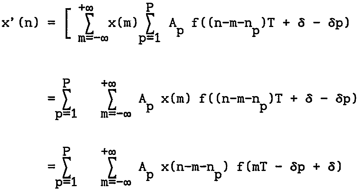
Afin de construire un système permettant de réaliser l'égalisation du signal reçu, on va ci-après exprimer le signal numérique reçu x'(n) en fonction du signal numérique émis x(n). In order to construct a system making it possible to equalize the received signal, the digital signal received x '(n) will now be expressed as a function of the digital transmitted signal x (n).
Pour cela, on va déterminer les différents signaux x(t), xe (t), xr(t), x'(t) enfin x'(n) en utilisant les signaux déjà connus. De plus, on utilise aussi le modèle du canal en posant
![]()
atténuation du trajet n p 6 : retard du trajet n p p
#(t) : fonction de dirac
D'autre part, dans ce calcul on suppose que le convertisseur numérique-analogique d'émission ainsi que le convertisseur analogique-numérique de réception sont parfaits et que les filtres sont linéraires.On peut donc écrire de ce fait
![]()
![]()
path attenuation np 6: path delay npp
# (t): function of dirac
On the other hand, in this calculation it is assumed that the transmit digital-to-analog converter as well as the receive digital-to-digital converter are perfect and that the filters are linear.
![]()
Le signal x'(t) reçu s'écrit x'(t) = x(t) * fe(t) * h(t) * f st) avec f (t) et fr(t) la
e e r
fonction de transfert des
filtres de mise en forme
d'émission et de réception
= x(t) * f (t) * fr(t) * h(t)
e r
= x(t) * f(t) * h(t) où f(t) représente la forme d'onde reçue sans canal.Généralement f(t) vérifie le 1 critère de Nyquist, à savoir f(t) = 1, t = O f(t) = O, t = kT R s IN, T période de modulation
Les formes d'ondes les plus couramment utlisées sont f(t) = sin(wt/T)/(wt/T) sinus cardinal f(t) = [sin(#t/T)/(#t/T)] x (cos (α#t/T)/(1-(2at/T))) cosinus surélevé COL : roff off factor)
En introduisant le modèle du canal donné par h(t), on peut écrire

eer
transfer function of
formatting filters
transmission and reception
= x (t) * f (t) * fr (t) * h (t)
st
= x (t) * f (t) * h (t) where f (t) represents the received waveform without channel. Generally f (t) satisfies the 1 Nyquist criterion, namely f (t) = 1 , t = O f (t) = O, t = kT R s IN, T modulation period
The most commonly used waveforms are f (t) = sin (wt / T) / (wt / T) cardinal sinus f (t) = [sin (# t / T) / (# t / T)] x (cos (α# t / T) / (1- (2at / T))) elevated cosine COL: roff off factor)
By introducing the model of the channel given by h (t), one can write
Ce signal est échantillonné au rythme t/T et on pose x'(n) = x'(t = nT + d) O < 6 < T déphasage instant
d'échantillonnage

sampling
On pose pour chaque muti-trajet : #p = np T + #p O # #p < T, np # N
Il vient
He comes
On suppose que f(t) décroit assez vite avec le temps pour que hors d'un intervalle [l1T, l2T] elle soit négligeable. Avec les formes généralement utilisées, ceci est vérifié. We suppose that f (t) decreases rather rapidly with time so that outside an interval [l1T, l2T] it is negligible. With the forms generally used, this is verified.
Il vient alors

On suppose ici, sans nuire à la généralité, que les indices des multi-trajets sont rangés par ordre de retards croissant avec Ti = O trajet direct Tp trajet de retard maximal alors

On voit que l'on peut mettre x'(n) sous la forme

où f'(m) dépend des Apf(mT-#p+#) p= l,...p
On peut réécrire
where f '(m) depends on Apf (mT- # p + #) p = 1, ... p
We can rewrite
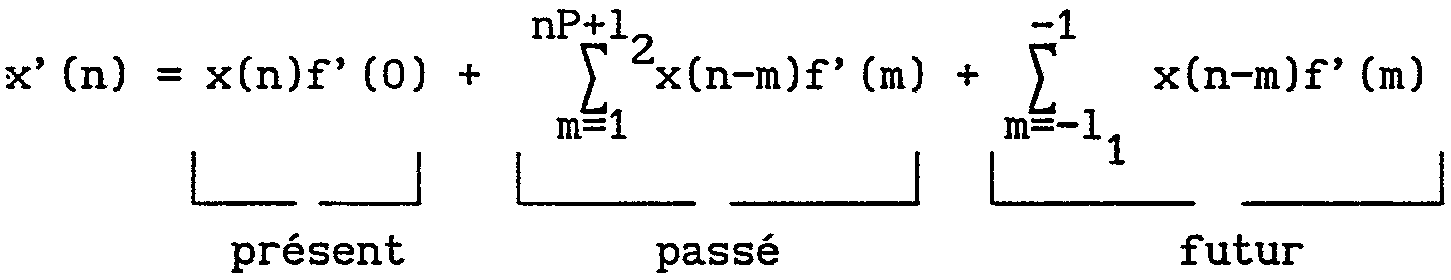
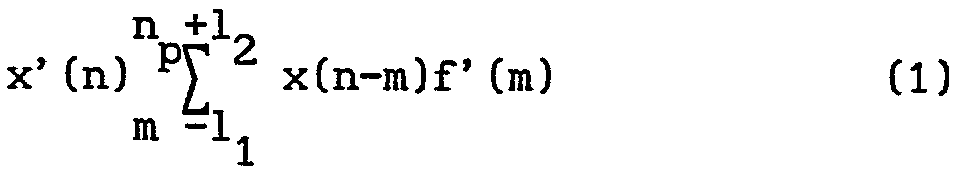
On voit que la donnée reçue x'(n) dépend de la donnée x(n), des (12 + n) données précédentes et des 11 données suivantes. It can be seen that the received data x '(n) depends on the data x (n), the (12 + n) previous data and the next 11 data.
Partant de l'équation l
on peut écrire le système permettant de réaliser l'égalisation du signal reçu.Starting from equation l
we can write the system to achieve the equalization of the received signal.
D'après l'équation l ci-dessus, on voit que la mémoire du canal est de (ll+ l2+ np)données. Ainsi conformément à la présente invention, pour réaliser l'égalisation d'un canal de transmission numérique, on émet les données par paquets-temporel de durée finie en insérant entre chaque paquet un signal de référence de durée fixe, dans le mode de réalisation donné ici, appelé bouchon. Ce bouchon présente une longueur supérieure ou égale à 11+ lz+ n données lui permettant donc d'absorber la p mémoire du canal. A titre d'exemple, on peut prendre un bouchon de 64 données permettant d'absorber des retards et des étalements de la forme d'onde d'au plus 64 T.On associe à ces 64 données, 448 données utiles à transmettre pour former des paquets de durée finie fixe de 512 données. From equation 1 above, it can be seen that the memory of the channel is (11 + 12 + np) given. Thus, in accordance with the present invention, in order to achieve the equalization of a digital transmission channel, the packet-time data of finite duration is transmitted by inserting between each packet a reference signal of fixed duration, in the given embodiment. here, called cap. This plug has a length greater than or equal to 11+ lz + n data allowing it to absorb the memory of the channel. For example, we can take a plug of 64 data to absorb delays and spreads of the waveform of at most 64 T. Associated with these 64 data, 448 useful data to be transmitted to form packages of fixed finite duration of 512 data.
Si on numérote ces paquets à partir d'une origine quelconque correspondant au premier échantillon d'un bouchon : 1,1,...I, I + l, ...on peut décrire un tel paquet par

x1(n) <SEP> l5oi2 <SEP> xl <SEP> + <SEP> n) <SEP> n <SEP> = <SEP> O, <SEP> ... <SEP> 511 <SEP>
<tb> x <SEP> (n) <SEP> = <SEP> x <SEP> (512 <SEP> x <SEP> I <SEP> + <SEP> n) <SEP> n <SEP> = <SEP> 0, <SEP> ... <SEP> 511 <SEP>
<tb> xxII(n)) <SEP> , <SEP> n <SEP> = <SEP> 0, <SEP> ... <SEP> 63 <SEP> -- > <SEP> bouchon
<tb> xI <SEP> (n) <SEP> , <SEP> n <SEP> = <SEP> 64 <SEP> ...<SEP> 511 <SEP> - > <SEP> données <SEP> utiles
<tb>
Compte tenu de la répétition du signal de référence ou bouchon, pour deux paquets émis quelconques I et J on peut écrire x1 (n) = xJ(n) VI,J V n E [O, ... 63]
De la même façon, les données reçues sont groupées en paquets de 512 données mais on prend comme origine de ème numérotation le (12 + np)ème me échantillon du bouchon reçu correspondant au trajet le plus court, à savoir le trajet direct.
Dans ce cas, on peut écrire x'I(n) = x'(512 x I + n + 12 + np) n = 0, ... 511

<tb> x <SEP> (n) <SEP> = <SEP> x <SEP> (512 <SEP> x <SEP> I <SEP> + <SEP> n) <SEP> n <SEP> = <SEP > 0, <SEP> ... <SEP> 511 <SEP>
<tb> xxII (n)) <SEP>, <SEP> n <SEP> = <SEP> 0, <SEP> ... <SEP> 63 <SEP>-><SEP> cap
<tb> xI <SEP> (n) <SEP>, <SEP> n <SEP> = <SEP> 64 <SEP> ... <SEP> 511 <SEP>-><SEP> useful <SEP> data
<Tb>
Given the repetition of the reference signal or plug, for any two transmitted packets I and J we can write x1 (n) = xJ (n) VI, JV n E [O, ... 63]
In the same way, the received data are grouped in packets of 512 data but one takes like origin of th numbering the (12 + np) th sample of the received cap corresponding to the shortest way, namely the direct path.
In this case, we can write x'I (n) = x '(512 x I + n + 12 + np) n = 0, ... 511
On pose xip(n) = x1 (n+p) n = O, ...511-P (permutation circulaire
I d'ordre P)
= x (p) n = 512 - P,511
Par exemple {x I3 (n)}=(xI(3), xI(4), ... xI(511), xI(O), xI(1), xI(2))
n = O, 511
Il vient compte tenu de la répétition du bouchon au début de chaque paquet

I of order P)
= x (p) n = 512 - P, 511
For example {x I3 (n)} = (xI (3), xI (4), ... xI (511), xI (O), xI (1), xI (2))
n = 0, 511
It comes considering the repetition of the cork at the beginning of each packet
Si on calcule la Transformée de Fourier discrète des deux termes de l'équation (2), on trouve

On pose

où le terme entre parenthèses représente la réponse en fréquence du filtre (donc du canal) décrit par l'équation (1) pour des fréquences multiples de 2# et où le deuxième terme est un
512 déphasage dû au décalage dans la numérotation de (l2+nP) échantillons. We pose
where the term in parentheses represents the frequency response of the filter (hence of the channel) described by equation (1) for multiple frequencies of 2 # and where the second term is a
512 phase shift due to offset in the numbering of (12 + nP) samples.
On peut donc écrire
![]()
![]()
où H(k) représente la réponse en
fréquence du canal de transmission (4)
Il est aisé de voir que
![]()
frequency of the transmission channel (4)
It is easy to see that
![]()
Autrement dit la connaissance de la réponse en fréquence du canal pour un déphasage de (lz+ n ) échantillons sur le trajet p direct permet de retrouver les données émises par transformée de
Fourier discrète inverse.In other words, the knowledge of the frequency response of the channel for a phase shift of (lz + n) samples on the direct path p allows to recover the data transmitted by transform of
Discrete Fourier inverse.
Le calcul de la réponse en fréquence du canal peut se faire par l'envoi d'un paquet-test dont la transformée de Fourier discrète est connue et disponible au récepteur. Selon un mode de réalisation de l'invention, ce paquet-test qui comprend les 64 données du bouchon suivies de 448 données fixes est émis pérodiquement à un rythme qui dépend de la stationnarité supposée du canal de transmission. The calculation of the frequency response of the channel can be done by sending a test packet whose discrete Fourier transform is known and available to the receiver. According to one embodiment of the invention, this test packet which comprises the plug data followed by 448 fixed data is transmitted periodically at a rate which depends on the supposed stationarity of the transmission channel.
Soit xT(n), n = 0,...511 ce paquet-test, Il lui correspond au récepteur un paquet x'T(n), n = 0,...511 où le premier ème échantillon est en phase avec le Cl +n ) échantillon du
2p bouchon pour le trajet direct. Dans ce cas, on peut calculer l'estimé de la réponse en fréquence du canal par
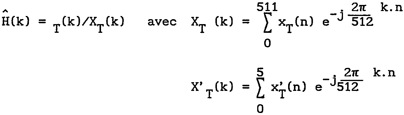
l'égalisation des données se fera alors par

et les données utiles seront récupérées pour n variant de 64 à 511.Let xT (n), n = 0, ... 511 be this test-packet, It corresponds to the receiver a packet x'T (n), n = 0, ... 511 where the first sample is in phase with the Cl + n) sample of the
2p plug for the direct route. In this case, the estimate of the frequency response of the channel can be calculated by
data equalization will then be done by
and the useful data will be retrieved for n ranging from 64 to 511.
Pour pouvoir calculer la réponse en fréquence du canal H(k) il faut insérer un signal de référence de durée fixe appelé bouchon entre chaque groupe de données utiles pour absorber la mémoire du canal. La longueur en échantillon du bouchon doit être supérieure ou égale à (12+ 11+ np) avec: np x T = retard du trajet le plus long 11 x T - étalement à gauche de la forme d'onde reçue 12 x T - étalement à droite de la forme d'onde reçue
D'autre part, pour pollvoir appliquer l'analyse de Fourier, éme il faut être calé, au niveau du récepteur, sur le (np+12) échantillon d'un bouchon sur le trajet le plus court, à savoir le trajet direct. I1 est donc nécessaire de repérer dans le flux des données arrivant au récepteur, l'endroit où se trouvent les bouchons. Pour repérer les données correspondant au bouchon dans le flux des données reçues, une solution consiste à faire une corrélation entre les données reçues et les données du bouchon émis en utilisant un système tel que représenté sur la figure 2.To be able to calculate the frequency response of the channel H (k), it is necessary to insert a reference signal of fixed duration called a plug between each group of useful data to absorb the memory of the channel. The sample length of the plug must be greater than or equal to (12 + 11+ np) with: np x T = delay of the longest path 11 x T - left spread of the received waveform 12 x T - spread right of the received waveform
On the other hand, in order to be able to apply Fourier analysis, it is necessary to be calibrated, at the level of the receiver, on the (np + 12) sample of a stopper on the shortest path, namely the direct path. It is therefore necessary to locate in the stream of data arriving at the receiver, the place where the plugs are located. In order to locate the data corresponding to the plug in the data stream received, one solution consists in correlating the data received with the data of the plug transmitted using a system as represented in FIG. 2.
Dans ce cas, les données reçues x' (n) sont envoyées sur un registre à décalage 10 comportant 64 étages, chaque sortie du registre à décalage est envoyée sur un multiplicateur 11 recevant en entrée une donnée conjuguée du bouchon émis b*(n) avec n variant entre 63 et O. Les sorties des multiplicateurs 11 sont envoyées vers des additionneurs 12 de telle sorte que chaque additionneur recoive la sortie issue de l'additionneur précédent et d'un multiplicateur 11 de manière à obtenir en sortie un signal C(n). Dans ce cas, quand les données reçues contiennent un bouchon émis ou l'une de ces répliques engrendrées par un multitrajet, la sortie |C(n) présente un pic de corrélation
comme représenté sur la figure 3 qui donne la courbe iC(n)f en fonction des échantillons.Le premier pic de corrélation qui correspond au trajet le plus court permet de se caler facilement sur le (12+np)ème échantillon du bouchon sur ce même trajet. De ce fait, on sera bien calé pour la découpe du flux entrant en blocs de 512 données. Cette corrélation entre les données reçues et les échantillons du bouchon peut être implantée en utilisant des transformée de Fourier d'ordre 512. Pour ce faire, le flux de données entrant est découpé avec une origine arbitraire en blocs de 512 échantillons et corrélé fréquentiellement avec les 64 échantillons du bouchon étendu à 512 à l'aide d'échantillons nuls. Le signal |C2(n)| est donc le résultat d'une corrélation circulaire entre les données reçues et le bouchon étendu à 512 échantillons avec des données nulles.De la même façon |C2(n)| présente des pics de corrélation qui permettentt de situer le premier échantillon du bouchon sur le trajet le plus direct et à partir de là, on peut se caler sur le Cl2+ ème np)èmeéchantillon pour découper le signal reçu en blocs de 512 données bien calées de manière à réaliser ensuite l'égalisation.In this case, the received data x '(n) are sent on a shift register 10 having 64 stages, each output of the shift register is sent on a multiplier 11 receiving as input a conjugate data of the plug issued b * (n) with n varying between 63 and 0. The outputs of the multipliers 11 are sent to adders 12 so that each adder receives the output from the preceding adder and a multiplier 11 so as to output a signal C ( not). In this case, when the received data contains an emitted plug or one of these replicas engrendrées by a multitrajet, the output | C (n) has a correlation peak
as shown in FIG. 3 which gives the curve iC (n) f as a function of the samples. The first correlation peak which corresponds to the shortest path makes it possible to easily lock on the (12 + np) th sample of the plug on this same journey. As a result, we will be well calibrated for the cutting of the incoming flow into blocks of 512 data. This correlation between the received data and the plug samples can be implemented by using 512 Fourier transforms. To do this, the incoming data stream is cut with an arbitrary origin in blocks of 512 samples and correlated frequently with the 512 samples. 64 samples of the plug extended to 512 using null samples. The signal | C2 (n) | is therefore the result of a circular correlation between the data received and the plug extended to 512 samples with zero data. Similarly | C2 (n) | presents correlation peaks that allow to locate the first sample of the plug on the most direct path and from there, we can focus on the Cl2 + th np) thesample to cut the received signal into blocks of 512 well-calibrated data of way to realize then the equalization.
Lorsque le signal émis présente des paquets-test, on utilise ces paquets-test afin de calculer la réponse en fréquence du canal.When the transmitted signal has test packets, these test packets are used to calculate the frequency response of the channel.
Il est donc nécessaire de se caler sur les paquets-test. Ceci peut être fait en corrélant les paquets de 512 données avec les 512 données du paquet-test. Une autre méthode consiste à calculer pour chaque bloc, la réponse impulsionnelle du canal à partir de la transformée de Fourier des paquets-test. La réponse impulsionnelle calculée sera faible sauf quand on sera en phase avec un paquet-test reçu. Ceci permet de se synchroniser sur le dit paquet-test.It is therefore necessary to lock on the test packs. This can be done by correlating the data packets with the data of the test packet. Another method consists in calculating for each block, the impulse response of the channel from the Fourier transform of the test packets. The computed impulse response will be low except when one is in phase with a received test packet. This makes it possible to synchronize on the said test-packet.
On décira maintenant avec référence aux figures 4 et 5 un mode de réalisation d'un émetteur et d'un récepteur permettant la mise en oeuvre du procédé conforme à la présente invention. Comme représenté sur la figure 4, dans l'émetteur permettant la mise en oeuvre du procédé de la présente invention en sortie du circuit 20 de codage des données numériques on connecte un circuit 21 de stockage des données utiles qui sont mises sous forme de paquets de 448 échantillons. De même ces données utiles sont envoyées vers un circuit permettant de constituer les paquets temporels dont la durée est connue du récepteur, à savoir des paquets de données de 512 échantillons. Pour constituer ces paquets, on insère au niveau du circuit 22 entre chaque paquet de 448 échantillons, 64 échantillons issus d'un circuit 23 émettant un signal de référence appelé bouchon.Ces données bouchons sont des données connues au niveau du récepteur, elles sont toujours identiques dans le mode de réalisation décrit. On obtient donc en sortie du circuit 22 un signal x (n) qui est envoyé vers un circuit 24 de mise en trame. Ce circuit 24 de mise en trame reçoit aussi les 512 données issues du circuit 25 de réalisation du paquet-test. Ce paquet-test est réalisé à l'aide de données test issues du circuit 26 et des données bouchons issues du circuit 23. Ce paquet-test est connu du récepteur et comporte 512 échantillons. I1 se répète périodiquement une fois par trame comme expliqué avec référence à la figure 1.Le signal x(n) issu du circuit 24 de mise en trame est envoyé alors de manière connue sur un convertisseur numérique analogique 27 donnant en sortie un signal analogique x(t) puis sur un filtre 28 donnant en sortie un signal mis en forme x (t) qui est alors émis de manière connue
e vers le récepteur. L'émetteur décrit est un émetteur mettant le signal sous forme de paquets temporels de durée finie fixe et utilisant les paquets-test. Comme mentionné ci-dessus, l'utilisation de paquets-test est optionnelle dans le cadre de la présente invention. De ce fait, l'émetteur pourrait très bien ne comporter que les circuits 20, 21, 22, 23, 27 et 28.It is now decided with reference to Figures 4 and 5 an embodiment of a transmitter and a receiver for carrying out the method according to the present invention. As shown in FIG. 4, in the transmitter enabling the implementation of the method of the present invention at the output of the digital data coding circuit 20, a useful data storage circuit 21 is connected which is put into the form of packet data. 448 samples. Similarly, this useful data is sent to a circuit for constituting the time packets whose duration is known to the receiver, namely 512 sample data packets. To constitute these packets, at the level of the circuit 22 is inserted between each packet of 448 samples, 64 samples from a circuit 23 emitting a reference signal called a plug.These plug data are known data at the receiver, they are always identical in the embodiment described. Thus, at the output of the circuit 22, a signal x (n) is obtained which is sent to a framing circuit 24. This framing circuit 24 also receives the data 512 from the circuit 25 for producing the test packet. This test packet is produced using test data from circuit 26 and plug data from circuit 23. This test packet is known to the receiver and comprises 512 samples. It is repeated periodically once per frame as explained with reference to FIG. 1.The signal x (n) originating from the framing circuit 24 is then sent in a known manner to a digital analog converter 27 giving an analog signal output. (t) then on a filter 28 outputting a shaped signal x (t) which is then emitted in a known manner
e to the receiver. The transmitter described is a transmitter putting the signal in the form of time packets of fixed finite duration and using the test packets. As mentioned above, the use of test packs is optional in the context of the present invention. As a result, the transmitter could very well only include circuits 20, 21, 22, 23, 27 and 28.
On décrira maintenant avec référence plus particulièrement à la figure 5, un récepteur permettant de recevoir les signaux Xe (t) émis par l'émetteur et de réaliser l'égalisation du canal de transmission. Ce récepteur comporte un filtre 30 Fr recevant le signal xr (t) et sortant un signal x'(t) qui est envoyé sur un convertisseur analogique-numérique 31 fonctionnant avec une horloge 1/T et donnant en sortie un signal numérique x'(n). Ce signal x'(n) est envoyé vers un circuit 32 de détermination des bouchons appelé synchro-bouchon qui peut être un circuit de corrélation tel que décrit ci-dessus et qui envoie vers un circuit 33 de découpe en paquet du signal x'(n) une information de synchronisation. D'autre part, le signal x'(n) est envoyé vers le circuit 33 de découpe en paquet.En sortie, on observe un 'I signal x' (n) formé de 512 échantillons qui sont envoyés respectivement vers un circuit 34 de détermination des synchro paquets-test et vers un circuit 35 de Transformation de Fourier
FFT. Le circuit 34 de détermination de la synchro paquet-test 34 détermine selon un des procédés décrit ci-dessus un signal de synchro-paquet qui est envoyé vers un multiplexeur 36 qui reçoit sur son entrée le signal X' (k) issu du circuit 35 de Transformée de Fourier et qui commute le signal respectivement soit vers un circuit 37 de calcul des coefficients de correction, soit vers un circuit 38 d'égalisation: Le circuit 37 de calcul des coefficients de correction envoie en sortie les 512 échantillons corrigés vers le circuit d'égalisation 38. En sortie du circuit 38 d'égalisation, on obtient le signal XI(k) qui est envoyé vers un circuit 39 de calcul de Transformée de Fourier inverse FFT1. We will now describe with reference more particularly to Figure 5, a receiver for receiving signals Xe (t) emitted by the transmitter and to achieve the equalization of the transmission channel. This receiver comprises a filter 30 Fr receiving the signal xr (t) and outputting a signal x '(t) which is sent on an analog-digital converter 31 operating with a clock 1 / T and outputting a digital signal x' ( not). This signal x '(n) is sent to a circuit 32 for determining plugs called synchro-plug which can be a correlation circuit as described above and which sends to a circuit 33 for packet cutting signal x' ( n) synchronization information. On the other hand, the signal x '(n) is sent to the circuit 33 of packet cutting. At the output, there is a signal I' x (n) formed of 512 samples which are sent respectively to a circuit 34 of determination of the test-packet sync and to a Fourier transform circuit
TFF. The circuit 34 for determining the test packet synchro 34 determines, according to one of the methods described above, a synchro-packet signal which is sent to a multiplexer 36 which receives on its input the signal X '(k) coming from the circuit 35. Fourier Transform and which switches the signal respectively to a circuit 37 for calculating the correction coefficients, or to an equalization circuit 38: The circuit 37 for calculating the correction coefficients outputs the 512 corrected samples to the circuit Equalization 38. At the output of the equalization circuit 38, the signal XI (k) is obtained which is sent to a circuit 39 for calculating the inverse Fourier Transform FFT1.
Ce circuit donne en sortie un signal xt(n) comportant 512 échantillons constitués de données bouchon et de données utiles.This circuit outputs a signal xt (n) comprising 512 samples consisting of plug data and payload data.
Cé signal ést envoyé sur un circuit 40 déterminant parmi ces échantillons les 448 données utiles qui sont alors envoyées vers un filtre 41 et vers un circuit de décodage 42.This signal is sent on a circuit 40 determining among these samples the 448 useful data which are then sent to a filter 41 and to a decoding circuit 42.
La présente invention a été décrite en se référant à des paquets temporels de durées fixes. Il est évident qu'elle peut aussi s'appliquer à des paquets temporels de durées variables. The present invention has been described with reference to time packets of fixed durations. It is obvious that it can also apply to time packets of variable duration.
D'autre part, les parties non décrites de l'émetteur et du récepteur sont réalisées comme connu de l'homme de l'art dans le cas d'une modulation de type MAQ-n. On the other hand, the undescribed parts of the transmitter and the receiver are realized as known to those skilled in the art in the case of a modulation of the MAQ-n type.
Claims (12)
Priority Applications (1)
| Application Number | Priority Date | Filing Date | Title |
|---|---|---|---|
| FR9113809A FR2683689A1 (en) | 1991-11-08 | 1991-11-08 | Method of frequency-based equalisation of a digital transmission channel, and transmitter and receiver for implementing the method |
Applications Claiming Priority (1)
| Application Number | Priority Date | Filing Date | Title |
|---|---|---|---|
| FR9113809A FR2683689A1 (en) | 1991-11-08 | 1991-11-08 | Method of frequency-based equalisation of a digital transmission channel, and transmitter and receiver for implementing the method |
Publications (2)
| Publication Number | Publication Date |
|---|---|
| FR2683689A1 true FR2683689A1 (en) | 1993-05-14 |
| FR2683689B1 FR2683689B1 (en) | 1995-01-20 |
Family
ID=9418763
Family Applications (1)
| Application Number | Title | Priority Date | Filing Date |
|---|---|---|---|
| FR9113809A Granted FR2683689A1 (en) | 1991-11-08 | 1991-11-08 | Method of frequency-based equalisation of a digital transmission channel, and transmitter and receiver for implementing the method |
Country Status (1)
| Country | Link |
|---|---|
| FR (1) | FR2683689A1 (en) |
Cited By (5)
| Publication number | Priority date | Publication date | Assignee | Title |
|---|---|---|---|---|
| FR2706232A1 (en) * | 1993-06-07 | 1994-12-16 | Alcatel Mobile Comm France | Signalling packet for a communications system |
| WO1994029971A1 (en) * | 1993-06-07 | 1994-12-22 | Alcatel Mobile Communication France | Signaling packet for communication system with modulated reference according to a time-base law |
| EP0717507A3 (en) * | 1994-12-13 | 1998-01-21 | AT&T Corp. | Modem receiver pre-emphasis |
| EP1119146A3 (en) * | 2000-01-20 | 2004-01-02 | Nortel Networks Limited | Frequency-domain equalisation |
| US7254171B2 (en) | 2000-01-20 | 2007-08-07 | Nortel Networks Limited | Equaliser for digital communications systems and method of equalisation |
Citations (5)
| Publication number | Priority date | Publication date | Assignee | Title |
|---|---|---|---|---|
| US3855422A (en) * | 1972-07-10 | 1974-12-17 | Ibm | Time division multiplexer with each frame consisting of a fixed length bit oriented address field and a variable length character oriented data field |
| GB1378811A (en) * | 1970-05-15 | 1974-12-27 | Gen Datacomm Ind Inc | Synchronous programmable mixed format time division multiplexer |
| US4058713A (en) * | 1976-09-20 | 1977-11-15 | General Signal Corporation | Equalization by adaptive processing operating in the frequency domain |
| US4152649A (en) * | 1976-07-08 | 1979-05-01 | International Business Machines Corporation | Channel equalization apparatus and method using the Fourier transform technique |
| WO1988005981A1 (en) * | 1987-02-02 | 1988-08-11 | Motorola, Inc. | Tdma communications system with adaptive equalization |
-
1991
- 1991-11-08 FR FR9113809A patent/FR2683689A1/en active Granted
Patent Citations (5)
| Publication number | Priority date | Publication date | Assignee | Title |
|---|---|---|---|---|
| GB1378811A (en) * | 1970-05-15 | 1974-12-27 | Gen Datacomm Ind Inc | Synchronous programmable mixed format time division multiplexer |
| US3855422A (en) * | 1972-07-10 | 1974-12-17 | Ibm | Time division multiplexer with each frame consisting of a fixed length bit oriented address field and a variable length character oriented data field |
| US4152649A (en) * | 1976-07-08 | 1979-05-01 | International Business Machines Corporation | Channel equalization apparatus and method using the Fourier transform technique |
| US4058713A (en) * | 1976-09-20 | 1977-11-15 | General Signal Corporation | Equalization by adaptive processing operating in the frequency domain |
| WO1988005981A1 (en) * | 1987-02-02 | 1988-08-11 | Motorola, Inc. | Tdma communications system with adaptive equalization |
Non-Patent Citations (1)
| Title |
|---|
| IEEE INTERNATIONAL CONFERENCE ON ACOUSTICS, SPEECH & SIGNAL PROCESSING ICASSP 1978, Oklahoma, US, 10.-12.04.1978, pages 100-104, IEEE, New York, US; D. MAIWALD et al.: 'An Adaptive Equalizer with Significant Reduced Number of Operations'. * |
Cited By (5)
| Publication number | Priority date | Publication date | Assignee | Title |
|---|---|---|---|---|
| FR2706232A1 (en) * | 1993-06-07 | 1994-12-16 | Alcatel Mobile Comm France | Signalling packet for a communications system |
| WO1994029971A1 (en) * | 1993-06-07 | 1994-12-22 | Alcatel Mobile Communication France | Signaling packet for communication system with modulated reference according to a time-base law |
| EP0717507A3 (en) * | 1994-12-13 | 1998-01-21 | AT&T Corp. | Modem receiver pre-emphasis |
| EP1119146A3 (en) * | 2000-01-20 | 2004-01-02 | Nortel Networks Limited | Frequency-domain equalisation |
| US7254171B2 (en) | 2000-01-20 | 2007-08-07 | Nortel Networks Limited | Equaliser for digital communications systems and method of equalisation |
Also Published As
| Publication number | Publication date |
|---|---|
| FR2683689B1 (en) | 1995-01-20 |
Similar Documents
| Publication | Publication Date | Title |
|---|---|---|
| EP1035699B1 (en) | Method for isolating a block frequency from a block formatted signal | |
| FR2623669A1 (en) | EQUALIZATION APPARATUS AND METHOD FOR DATA TRANSMISSION | |
| FR2571566A1 (en) | DIGITAL DATA RECEIVING DEVICE HAVING AN ADAPTIVE RHYTHM RECOVERY DEVICE | |
| EP0116387B1 (en) | Method of initializing the filter coefficients in a compensation device for near and far echoes, and device for performing this method | |
| EP0081437B1 (en) | Echo cancelling system | |
| FR2588680A1 (en) | DEVICE FOR CALCULATING A DISCRETE FOURIER TRANSFORMER, AND ITS APPLICATION TO PULSE COMPRESSION IN A RADAR SYSTEM | |
| EP0039980B1 (en) | Adaptive digital data receiving system with compensation of the amplitude and phase distortions introduced by the data transmission channel | |
| FR2480534A1 (en) | METHOD AND DEVICE FOR CANCELING ECHO IN A DATA TRANSMISSION SYSTEM | |
| EP1330091B1 (en) | Method of selecting a position of a FFT window in a COFDM receiver | |
| FR2635420A1 (en) | METHOD AND DEVICE FOR DEMODULATING SIGNALS WITH A CONSTANT ENVELOPE AND A CONTINUOUS PHASE ANGULARLY MODULATED BY A TRAIN OF BINARY SYMBOLS, TOLERATING THE FREQUENCY DERIVATIVES | |
| CA1108707A (en) | Auto-adaptative equalizer | |
| FR2683689A1 (en) | Method of frequency-based equalisation of a digital transmission channel, and transmitter and receiver for implementing the method | |
| EP1074128B1 (en) | Multicarrier signal receiver with correction of equalization faults induced by the trf window displacements | |
| EP0127544B1 (en) | Echo canceller with an adaptive digital filter for a transmission system | |
| EP1113634A1 (en) | Method for transmission channel estimation | |
| EP0688476B1 (en) | Digital time signal filtering method and device for transmission channel echo correction | |
| EP2074705B1 (en) | Method and devices for estimating crosstalk coefficients when a line is taken into operation | |
| EP0035295A1 (en) | Clock phase control method for a digital data receiving system, phase recovery circuit for carrying out this method and digital data receiving system comprising this circuit | |
| EP0702467B1 (en) | Digital transmission system synchronizable on initialization sequences | |
| EP1244243A1 (en) | Global MMSE equalisation | |
| EP1826973B1 (en) | Method and device to estimate the transfer function of the transmission channel for a COFDM modulator | |
| RU2002107017A (en) | METHOD FOR ASSESSING INTERFERENCE IN A COMMUNICATION SYSTEM | |
| FR2669493A1 (en) | Equalisation device for correcting long echoes | |
| EP1252722B1 (en) | Cdma radiocommunication method with access codes and corresponding receiver | |
| FR3022419A1 (en) | METHOD OF ESTIMATING A RADIO PROPELLATION CHANNEL |
Legal Events
| Date | Code | Title | Description |
|---|---|---|---|
| TP | Transmission of property | ||
| ST | Notification of lapse | ||
| ST | Notification of lapse |