FR2652974A1 - Television signal decoding device - Google Patents
Television signal decoding device Download PDFInfo
- Publication number
- FR2652974A1 FR2652974A1 FR8913091A FR8913091A FR2652974A1 FR 2652974 A1 FR2652974 A1 FR 2652974A1 FR 8913091 A FR8913091 A FR 8913091A FR 8913091 A FR8913091 A FR 8913091A FR 2652974 A1 FR2652974 A1 FR 2652974A1
- Authority
- FR
- France
- Prior art keywords
- decoding
- frames
- sep
- rate
- output
- Prior art date
- Legal status (The legal status is an assumption and is not a legal conclusion. Google has not performed a legal analysis and makes no representation as to the accuracy of the status listed.)
- Granted
Links
Classifications
-
- H—ELECTRICITY
- H04—ELECTRIC COMMUNICATION TECHNIQUE
- H04N—PICTORIAL COMMUNICATION, e.g. TELEVISION
- H04N7/00—Television systems
- H04N7/015—High-definition television systems
- H04N7/0152—High-definition television systems using spatial or temporal subsampling
- H04N7/0155—High-definition television systems using spatial or temporal subsampling using pixel blocks
- H04N7/0157—High-definition television systems using spatial or temporal subsampling using pixel blocks with motion estimation, e.g. involving the use of motion vectors
-
- H—ELECTRICITY
- H04—ELECTRIC COMMUNICATION TECHNIQUE
- H04N—PICTORIAL COMMUNICATION, e.g. TELEVISION
- H04N19/00—Methods or arrangements for coding, decoding, compressing or decompressing digital video signals
- H04N19/90—Methods or arrangements for coding, decoding, compressing or decompressing digital video signals using coding techniques not provided for in groups H04N19/10-H04N19/85, e.g. fractals
- H04N19/98—Adaptive-dynamic-range coding [ADRC]
Abstract
Description
La présente invention concerne un dispositif de décodage de signaux de télévision ayant préalablement été codés à l'émission en vue d'une transmission à une fréquence de trame déterminée et par l'intermédiaire d'un canal analo gique à bande passante limitée impliquant un traitement de réduction de la quantité d'informations à transmettre, ladite transmission étant réalisée selon un rythme temporel qui varie suivant le mouvement constaté dans les image d'origine à transmettre et de telle façon que ladite transmission soit opérée soit à un premier rythme à ladite fréquence de trame, soit à un deuxième rythme à une fréquence de trame deux fois plus faible, soit à un troisième rythme à une fréquence de trame quatre fois plus faible, et des informations relatives au mouvement et au rythme sélectionné étant également transmises. The present invention relates to a device for decoding television signals previously coded on transmission for transmission at a given frame rate and via a limited bandwidth analog channel involving a processing. reducing the amount of information to be transmitted, said transmission being performed according to a temporal rhythm which varies according to the movement observed in the original image to be transmitted and in such a way that said transmission is operated either at a first rate at said frequency frame, either at a second rate at a frame rate of two times lower, or at a third rate at a frame rate four times lower, and information relating to the selected movement and rate is also transmitted.
La demande de brevet français nO 8805010, déposée le 15 avril 1988 et non encore publiée à la date de dépôt de la présente demande, décrit notamment un dispositif de décodage de signaux de télévision destiné à être inclus dans la partie réception d'un système de transmission d'images de télévision à haute définition. Un tel système comprend lui-même, dans sa partie émission, un étage d'émission d'informations codées correspondant auxdites images et transmises par l'intermédiaire d'un canal analogique. Ce canal est à bande passante limitée par rapport à celle que nécessiterait la transmission de toutes les informations à haute définition.La transmission par ce canal, dit compatible puisque permettant la transmission des signaux de télévision au standard normal actuel (625 lignes, 50 Hz, 2:1) implique donc un traitement de réduction, ou de compression, de la quantité d'informations à transmettre, et ce traitement est opéré par exemple à l'aide d'un dispositif de codage tel que celui décrit dans le document cité ci-dessus. French patent application No. 8805010, filed on April 15, 1988 and not yet published at the filing date of the present application, notably describes a television signal decoding device intended to be included in the reception part of a television reception system. transmission of high definition television images. Such a system itself comprises, in its transmission part, a coded information transmission stage corresponding to said images and transmitted via an analog channel. This channel has a limited bandwidth compared to that which would require the transmission of all the information with high definition. The transmission by this channel, said compatible since allowing the transmission of the television signals to the current normal standard (625 lines, 50 Hz, 2: 1) therefore implies a reduction or compression treatment of the quantity of information to be transmitted, and this processing is performed for example by means of a coding device such as that described in the document cited above. -above.
Le dispositif de décodage décrit dans le document cité comprend, essentiellement, tout d'abord trois branches de traitement des informations transmises. La figure 1, reprise dudit document, montre ces trois branches désignées de façon générale par les références 101 à 103. La branche 101 comprend successivement un circuit d'interpolation dynamique 111 (pour une insertion des zéros à rétablir après transmission dans le canal analogique 10, du fait du sous-échantillonnage qui a été opéré avant cette transmission), un multiplexeur 112 recevant des informations de mouvement en provenance d'un canal 20 d'assistance numérique, et un circuit 114 de postfiltrage spatial délivrant une image 1250 a., r 50 Hz, 2:1, 1440 points/ligne.La branche 102 comprend successivement un circuit d'interpolation dynamique 121, un circuit à retard 122, un additionneur 123 des sorties des circuits 121 et 122, un circuit de postfiltrage spatial 124, un circuit de reconstitution d'image composé de deux mémoires en série 125 et 126, recevant les informations de mouvement transmises par le canal 20, et d'un additionneur 127, et un commutateur 128, qui reçoit d'une part la sortie de la mémoire 125 et d'autre part celle de l'additionneur 127 et qui délivre également une image 1250 a., r 50 Hz, 2:1, 1440 point/ligne.La branche 103 comprend successivement un circuit d'interpolation dynamique 131, un multiplexeur 132 recevant aussi des informations de mouvement en provenance du canal 20, un filtre temporel 135, un filtre spatial 136, un circuit à retard 137, un filtre spatial 136, un circuit à retard 137 et un commutateur 138 recevant alternativement la sortie de ce circuit à retard et celle du filtre 136 pour délivrer là encore une image 1250 a., 50 Hz, 2:1, 1440 points/ligne. Les sorties des branches 101, 102, 103 sont envoyées respectivement vers les entrées 141, 142, 143 d'un circuit d'aiguillage 140, dont le rôle est de sélectionner, en fonction d'un signal de décision également transmis par le canal 20, celle des sorties de branche qui convient et de délivrer finalement les signaux constitutifs des images à haute définition à reconstruire. The decoding device described in the cited document essentially comprises, first of all, three branches of processing the transmitted information. FIG. 1, taken from said document, shows these three branches generally designated by the references 101 to 103. The branch 101 successively comprises a dynamic interpolation circuit 111 (for insertion of the zeros to be restored after transmission in the analog channel 10 , because of the subsampling which has been performed before this transmission), a multiplexer 112 receiving motion information from a digital assistance channel 20, and a spatial post-filtering circuit 114 delivering an image 1250 a., r 50 Hz, 2: 1, 1440 points / line.The branch 102 comprises successively a dynamic interpolation circuit 121, a delay circuit 122, an adder 123 of the outputs of the circuits 121 and 122, a spatial post-filtering circuit 124, an image reconstruction circuit composed of two series memories 125 and 126, receiving the motion information transmitted by the channel 20, and an adder 127, and a switch 1 28, which receives on the one hand the output of the memory 125 and on the other hand that of the adder 127 and which also delivers an image 1250 a., R 50 Hz, 2: 1, 1440 point / line. 103 comprises successively a dynamic interpolation circuit 131, a multiplexer 132 also receiving motion information from the channel 20, a temporal filter 135, a spatial filter 136, a delay circuit 137, a spatial filter 136, a circuit delay 137 and a switch 138 alternately receiving the output of this delay circuit and that of the filter 136 to again deliver an image 1250 a., 50 Hz, 2: 1, 1440 points / line. The outputs of the branches 101, 102, 103 are respectively sent to the inputs 141, 142, 143 of a switching circuit 140, whose role is to select, according to a decision signal also transmitted by the channel 20 that of the appropriate branch outputs and finally deliver the constituent signals of the high definition images to be reconstructed.
On avait rappelé, plus haut, que les images d'origine, étant à haute définition, avaient dû être comprimées pour être transmises dans le canal analogique. On précisera ici que, dans le cas dudit document, cette compression a été opérée, à l'émission, dans un dispositif de codage comprenant lui-même trois branches de traitement situées en parallèle et recevant chacune la suite des images haute définition d'origine, un circuit de prise de décision relative au rythme de transmission et destiné à délivrer à partir des images d'origine et des images traitées par lesdites branches un signal de décision envoyé vers le canal d'assistance numérique associé au canal analogique, et un circuit d'aiguillage des sorties des branches selon le signal de sortie dudit circuit de décision, ce dispositif de codage étant remarquable en ce que
(a) les images d'origine successives étant définies par leur rang 2k-1, 2k, 2k+1, etc... dans ladite suite, ledit dispositif de codage comprend également un étage d'estimation de mouvement destiné à délivrer des informations relatives au mouvement des blocs composant les images de parité déterminée, par exemple de rang 2k+1, par rapport aux blocs correspondants des images de parité opposée, ici de rang 2k et 2k+2, qui entourent celles-ci
(b) lesdites branches, destinées à délivrer trois séquences d'images comprimées contenant le même nombre d'échantillons à transmettre à la fréquence de trame, comprennent elles-mêmes chacune un filtre spatial distinct
(c) le circuit de prise de décision comprend, en parallèle, trois voies de calcul de distorsion entre les images d'origine et les trois images traitées respectivement disponibles en aval desdits premier, deuxième et troisième filtres spatiaux des trois branches, et un circuit de comparaison desdites trois distorsions et de sélection de l'indice de branche correspondant à la plus faible de ces distorsions, la deuxième de ces trois voies de calcul recevant lesdites informations de mouvement relatives à chaque bloc d'image en vue d'une reconstitution d'une approximation des images de parité déterminée à partir des deux images de parité opposée qui les entourent chacune.It had been recalled, above, that the original images, being high definition, had to be compressed to be transmitted in the analog channel. It will be specified here that, in the case of said document, this compression has been operated, on transmission, in a coding device comprising itself three parallel processing branches and each receiving the sequence of the original high definition images. a decision-making circuit relating to the transmission rate and intended to deliver from the original images and images processed by said branches a decision signal sent to the digital assistance channel associated with the analog channel, and a circuit branch branches according to the output signal of said decision circuit, this coding device being remarkable in that
(a) the successive original images being defined by their rank 2k-1, 2k, 2k + 1, etc. in said sequence, said coding device also comprises a motion estimation stage intended to deliver information relating to the movement of the blocks composing the images of determined parity, for example of rank 2k + 1, with respect to the corresponding blocks of the images of opposite parity, here of rank 2k and 2k + 2, which surround them
(b) said branches, intended to deliver three compressed image sequences containing the same number of samples to be transmitted at the frame rate, each of them each comprise a separate spatial filter
(c) the decision-making circuit comprises, in parallel, three ways of calculating distortion between the original images and the three processed images respectively available downstream of said first, second and third spatial filters of the three branches, and a circuit comparing said three distortions and selecting the branch index corresponding to the smallest of these distortions, the second of these three calculation channels receiving said motion information relating to each image block for a reconstruction of an approximation of the parity images determined from the two images of opposite parity which surround them each.
Avec la structure de dispositif de codage ainsi définie, les images d'origine, à haute définition, comprenant ici 1152 lignes de 1440 points et divisées spatialement en blocs de 16 lignes de 16 points, sont transmises par le canal analogique selon un rythme temporel qui varie suivant le mouvement contenu dans chaque bloc.Ces trois rythmes possibles de transmission des blocs d'image sont ici les suivants
- le rythme 20 millisecondes (20 ms), selon lequel les informations correspondant à une image sont transmises en une seule trame, à la fréquence de trame égale à 50 Hz
- le rythme 40 millisecondes (40 ms), selon lequel les informations sont transmises en deux trames successives, à une fréquence deux fois plus faible (25 Hz)
- le rythme 80 millisecondes (80 ms), selon lequel les informations sont transmises en quatre trames successives, à une fréquence quatre fois plus faible (12,5 Hz).With the coding device structure thus defined, the original high-definition images, here comprising 1152 lines of 1440 points and spatially divided into blocks of 16 lines of 16 points, are transmitted by the analog channel according to a temporal rhythm which varies according to the movement contained in each block. These three possible rhythms of transmission of the image blocks are here as follows:
the 20 millisecond (20 ms) rate, according to which the information corresponding to an image is transmitted in a single frame, at the frame frequency equal to 50 Hz
the 40 millisecond (40 ms) rate, according to which the information is transmitted in two successive frames, at a frequency which is one half as low (25 Hz)
the 80 millisecond (80 ms) rate, according to which the information is transmitted in four successive frames at a frequency four times lower (12.5 Hz).
Pour être compatibles avec le standard MAC destiné ici à assurer leur transmission, les images à l'entrée du canal analogique comprennent 576 lignes (= 1152/2) de 720 échantillons (= 1440/2), et les deux trames composant ces images comportent donc 288 lignes de 720 points chacune. Les trames réellement transmises vont être par la suite regroupées par périodes de 80 ms, c'est-à-dire en séquences de quatre trames
T1, T2, T3, T41 qui sont les trames transmises et reçues et qui constituent donc les trames d'entrée du dispositif de décodage décrit plus loin.To be compatible with the MAC standard intended here to ensure their transmission, the images at the input of the analog channel comprise 576 lines (= 1152/2) of 720 samples (= 1440/2), and the two frames composing these images comprise therefore 288 lines of 720 points each. The frames actually transmitted will be subsequently grouped by periods of 80 ms, that is to say in sequences of four frames
T1, T2, T3, T41 which are the frames transmitted and received and which therefore constitute the input frames of the decoding device described below.
Les figures 2 à 4 rappellent, selon chacun des trois rythmes de transmission, les positions des échantillons dans les blocs à transmettre et le numéro de trame qui leur est affecté pour les récupérer lors de leur transmission. Plus précisément, sur les figures 2a à 2c qui concernent le rythme 20 ms, la figure 2a montre d'une manière générale la position des échantillons à transmettre à 50 Hz selon qu'ils appartiennent aux trames transmises T1 et T3 (échantillons représentés par des croix) ou bien T2 et T4 (échantillons représentés par des cercles). Les points indiquent sur ces figures 2a à 2c et les suivantes (3a à 3c, 4a à 4b) les échantillons manquants du bloc d'image à haute définition représenté.Les figures 2b et 2c montrent de façon spécifique, pour ce même bloc d'image, les échantillons transmis respectivement par les trames T1 et T2 (figure 2b) et par les trames T3 et T4 (figure 2c), le repérage des échantillons étant effectué à l'aide de l'indice de trame 1, 2, 3 ou 4 correspondant. Figures 2 to 4 remind, according to each of the three transmission rates, the positions of the samples in the blocks to be transmitted and the frame number assigned to them to recover them during transmission. More precisely, in FIGS. 2a to 2c which concern the 20 ms rate, FIG. 2a generally shows the position of the samples to be transmitted at 50 Hz depending on whether they belong to the transmitted frames T1 and T3 (samples represented by FIGS. cross) or T2 and T4 (samples represented by circles). The dots indicate in these figures 2a to 2c and the following (3a to 3c, 4a to 4b) the missing samples of the high-definition image block shown. FIGS. 2b and 2c show in a specific manner, for this same block of image, the samples respectively transmitted by the frames T1 and T2 (FIG. 2b) and by the frames T3 and T4 (FIG. 2c), the identification of the samples being carried out using the frame index 1, 2, 3 or 4 correspondent.
De même, la figure 3a montre d'une manière générale la position des échantillons (en nombre deux fois plus grand par rapport au cas précédent, et à transmettre à 25 Hz, en un intervalle de temps double) selon qu'ils appartiennent aux trames transmises T2 et T4 (cercles) ou T1 et T3 (des croix remplaçant alors les cercles), et les figures 3b et 3c montrent de façon spécifique, pour le même bloc, les échantillons transmis par les trames T1 et T2 (figure 3b) et par les trames T3 et T4 (figure 3c). Similarly, FIG. 3a generally shows the position of the samples (in number twice as large compared to the previous case, and to transmit at 25 Hz, in a double time interval) as they belong to the frames. transmitted T2 and T4 (circles) or T1 and T3 (crosses then replacing the circles), and Figures 3b and 3c specifically show, for the same block, the samples transmitted by the frames T1 and T2 (Figure 3b) and by the frames T3 and T4 (FIG. 3c).
Enfin, la figure 4a montre d'une manière générale la position des échantillons (en nombre quatre fois plus grand que celui observé dans le cas de la transmission à 50 Hz, et à transmettre à 12,5 Hzl en un intervalle de temps quatre fois plus grand), et la figure 4b montre de façon spécifique, pour le même bloc, les échantillons transmis par les trames T1, T2,
T3 et T4.Finally, Figure 4a shows in a general way the position of the samples (in number four times larger than that observed in the case of the transmission at 50 Hz, and to transmit at 12.5 Hzl in a time interval four times larger), and FIG. 4b specifically shows, for the same block, the samples transmitted by the frames T1, T2,
T3 and T4.
A ces trames T1 à T4 transmises, reçues successivement à l'entrée du dispositif de décodage, correspondent en sortie de ce dispositif de décodage quatre trames décodées notées Di, D2, Dg, D4. Chacune de ces trames décodées peut, bien entendu, contenir des blocs d'image correspondant à l'un quelconque des rythmes possible de transmission (20, 40 ou 80 ms), puisque le codage à l'émission prévoit, en sortie des branches de traitement correspondant à chaque rythme de transmission, un aiguillage par bloc. On appellera tn(20), tn(40), tn(80) ces blocs non sous-échantillonnés, selon le rythme de 20, 40 ou 80 ms auquel ils correspondent et en désignant par n l'indice de trame.Chaque trame Tn transmise contient donc en général des informations relatives aux trois rythmes 20, 40, 80 ms, et l'on désignera par Tn(20),
Tn(40), Tn(80) ces informations.To these transmitted frames T1 to T4, successively received at the input of the decoding device, correspond at the output of this decoding device four decoded frames denoted Di, D2, Dg, D4. Each of these decoded frames may, of course, contain picture blocks corresponding to any one of the possible transmission rhythms (20, 40 or 80 ms), since the transmission coding provides, at the output of the branches of processing corresponding to each transmission rate, a block referral. These non-subsampled blocks are called tn (20), tn (40), tn (80) at the rate of 20, 40, or 80 ms to which they correspond and denoting the frame index by n.Each frame Tn transmitted generally contains information relating to the three rhythms 20, 40, 80 ms, and will be designated by Tn (20),
Tn (40), Tn (80) this information.
Ces désignations étant précisées, les trames décodées sont obtenues, à partir des informations transmises, de la façon suivante
(a) le décodage de blocs t1(20) est obtenu à partir d'information transmises T1(20), et de même celui de blocs t2(20), t3(20), t4(20), à partir d'informations transmises
T2(20), T3(20), T4(20) respectivement.These designations being specified, the decoded frames are obtained, from the information transmitted, as follows
(a) the decoding of blocks t1 (20) is obtained from information transmitted T1 (20), and likewise that of blocks t2 (20), t3 (20), t4 (20), from information transmitted
T2 (20), T3 (20), T4 (20) respectively.
(b) le décodage de blocs t1(40) est obtenu à partir d'informations transmises T1(40) et T2(40), et celui de blocs t3(40) à partir d'informations transmises T3(40) et
T4(40). Les blocs relatifs aux trames décodées D2 et D4, dans le cas du rythme 40 ms, n'ont en effet pas été transmis, mais par contre on a transmis, pour chaque bloc manquant, l'information de mouvement (ou vecteur de déplacement) correspondante : pour chaque bloc de la deuxième trame le vecteur de déplacement V2, pour chaque bloc de la quatrième trame le vecteur de déplacement V4, etc.... Le décodage des blocs, dans ce cas du rythme 40 ms, est alors, comme on l'a vu, obtenu, pour les deuxième et quatrième trames non transmises, à l'aide d'une interpolation temporelle compensée en mouvement.Le principe de cette opération de compensation de mouvement est d'effectuer la demi-somme des trames transmises adjacentes dans la direction du mouvement estimé entre elles à l'aide des vecteurs de déplacement. Plus précisément, en utilisant les blocs des trames précédente et suivante ainsi que les vecteurs de déplacement correspondants, cette opération peut s'écrire
t2(40) = 1/2 t1(40) déplacé du vecteur -V2
+ 1/2 t3(40) déplacé du vecteur +V2
t4(40) = 1/2 t3(40) déplacé du vecteur -V4
+ 1/2 t5(40) déplacé du vecteur +V4.(b) the decoding of blocks t1 (40) is obtained from transmitted information T1 (40) and T2 (40), and that of blocks t3 (40) from transmitted information T3 (40) and
T4 (40). The blocks relating to the decoded frames D2 and D4, in the case of the 40 ms rate, have not been transmitted, but on the other hand, for each missing block, the motion information (or displacement vector) has been transmitted. corresponding: for each block of the second frame the displacement vector V2, for each block of the fourth frame the displacement vector V4, etc. The decoding of the blocks, in this case the 40 ms rate, is then, as as we have seen, obtained for the second and fourth non-transmitted frames, using a motion compensated temporal interpolation. The principle of this motion compensation operation is to perform the half-sum of the transmitted frames. adjacent in the direction of movement estimated from each other by the displacement vectors. More precisely, by using the blocks of the preceding and following frames as well as the corresponding displacement vectors, this operation can be written
t2 (40) = 1/2 t1 (40) moved from vector -V2
+ 1/2 t3 (40) moved from vector + V2
t4 (40) = 1/2 t3 (40) moved from vector -V4
+ 1/2 t5 (40) moved from vector + V4.
(c) le décodage des blocs t1(80), t2(80), t3(80), t4(80) est obtenu à partir d'informations transmises Tu(80),
T2(80, T3(80), T4(80).(c) the decoding of blocks t1 (80), t2 (80), t3 (80), t4 (80) is obtained from transmitted information Tu (80),
T2 (80, T3 (80), T4 (80).
Un schéma de principe, donné sur la figure 5, permet de présenter de façon synthétique ces opérations
- les données sous-échantillonnées Tn(20),
Tn(40), Tn(80) transmises aux rythmes respectifs de 20, 40, 80 ms sont respectivement envoyées vers des filtres d'interpolation spatiale FS(20), FS(40), FS(80) correspondants, destinés à reconstituer les échantillons absents du fait du sous-échantillonnage
- cette interpolation à une cadence propre à chaque rythme de transmission conduit à disposer de blocs t1(20), t2(20), t3(20), t4(20) en sortie du filtre FS(20), de blocs t1(80), t2(80), t3(80), t4(80) en sortie du filtre FS(80), et, en sortie du filtre FS(40), d'une part de blocs t1(40), t3(40) non interpolés temporellement, d'autre part de blocs t2(40), t4(40) ayant subi ladite interpolation temporelle compensée en mouvement dans un circuit référencé ici FIT
- un circuit d'aiguillage S reçoit en parallèle les blocs tn(40), interpolés ou non, les blocs tn(20) et les blocs tn(80), et sélectionne, selon le signal de sortie du circuit de prise de décision (transmis par le canal d'assistance numérique 20 noté DATV, en anglais : "Digitally
Assisted TeleVision), ceux qui correspondent au rythme de transmission.A schematic diagram, given in FIG. 5, makes it possible to summarize these operations
the subsampled data Tn (20),
Tn (40), Tn (80) transmitted at the respective rates of 20, 40, 80 ms are respectively sent to corresponding spatial interpolation filters FS (20), FS (40), FS (80), intended to reconstruct the samples absent due to under-sampling
this interpolation at a rate specific to each transmission rate leads to having blocks t1 (20), t2 (20), t3 (20), t4 (20) at the output of the filter FS (20), blocks t1 (80). ), t2 (80), t3 (80), t4 (80) at the output of the FS filter (80), and at the output of the FS filter (40), on the one hand blocks t1 (40), t3 (40), ) not interpolated temporally, on the other hand blocks t2 (40), t4 (40) having undergone said temporal interpolation compensated in motion in a circuit referenced here FIT
a switching circuit S receives in parallel the blocks tn (40), interpolated or not, the blocks tn (20) and the blocks tn (80), and selects, according to the output signal of the decision-making circuit ( transmitted by digital assistance channel 20 noted DATV, in English: "Digitally
Assisted TeleVision), those that correspond to the transmission rate.
Les principes décrits jusqu'à présent présentent cependant un inconvénient, comme le montre la figure 6, lorsqu'on se trouve en bordure de bloc d'image, en raison de ce qu'on appelle l'horizon H des filtres. Le filtrage des données en bordure d'un bloc Bc (pour un point filtré DA par exemple) implique parfois, en effet, de disposer de données à l'extérieur de ce bloc Bc considéré, ici dans un bloc BV. The principles described so far, however, have a disadvantage, as shown in Figure 6, when one is at the edge of the image block, because of what is called the horizon H filters. The filtering of the data at the edge of a block Bc (for a filtered point DA for example) sometimes implies, in fact, having data outside this block Bc considered here in a block BV.
Or ces données extérieures ont peut être été transmises au même rythme que celles du bloc considéré, mais ont pu également être transmises à un rythme différent, et n'ont pas, dans ce dernier cas, été échantillonnées suivant une maille d'échantillonnage compatible avec ledit filtrage. Cette situation est particulièrement gênante pour la deuxième voie de traitement restituant l'information transmise, avec le rythme de transmission 40 ms, car le processus de compensation de mouvement employé pour l'interpolation temporelle des blocs non transmis peut rejeter le point DA à l'extérieur du bloc
Bv.However, these external data may have been transmitted at the same rate as those of the block considered, but could also be transmitted at a different rate, and in the latter case they have not been sampled according to a sampling mesh compatible with said filtering. This situation is particularly troublesome for the second processing channel restoring the transmitted information, with the transmission rate 40 ms, since the motion compensation process used for the temporal interpolation of the non-transmitted blocks can reject the point DA at the same time. outside the block
Bv.
Un premier but de l'invention est de remédier à cet inconvénient qui se manifeste en bordure de bloc, en proposant un dispositif de décodage qui met en oeuvre une solution permettant d'effectuer le filtrage même dans cette situation-limite. A first object of the invention is to overcome this disadvantage which manifests itself at the edge of the block, by proposing a decoding device which implements a solution making it possible to perform the filtering even in this limit situation.
L'invention concerne à cet effet un dispositif de décodage de signaux de télévision caractérisé en ce qu'il comprend
(a) six mémoires de trame en série, dont les entrées et sorties sont prévues pour délivrer sept trames successives T4k+1 à T4k+7 transmises par ledit canal analogique à ladite fréquence de trame
(b) un aiguilleur prévu pour recevoir sur sept entrées respectives lesdites sept trames successives T4k+1 à T4k+7
(c) une première voie de décodage prévue pour recevoir les trames T4k+I, T4k+2 T4k+3 ou les trames
T4k+1, T4k+31 T4k+4 et comprenant en série un premier circuit de restitution de maille au deuxième rythme, un premier filtre d'interpolation spatiale, et un premier circuit de compensation de mouvement
(d) une deuxième voie de décodage prévue pour recevoir les trames T4k+1, T4k+3, T4k+4 ou les trames T4k+5 T4k+6, T4k+7 et comprenant en série un deuxième circuit de restitution de maille au deuxième rythme, un deuxième filtre d'interpolation spatiale, et un deuxième circuit de compensation de mouvement, les deux circuits de compensation de mouvement étant destinés à fonctionner simultanément et uniquement une trame sur deux
(e) un additionneur des sorties desdites première et deuxième voies de décodage
(f) une troisième voie de décodage prévue pour recevoir les trames T4k+1 à T4k+4 et comprenant en série un circuit de reconstitution de maille au premier rythme et un troisième filtre d'interpolation spatiale
(g) une quatrième voie de décodage prévue pour recevoir les trames T4k+1 à T4k+4 et comprenant en série un circuit de reconstitution de maille au troisième rythme et un quatrième filtre d'interpolation spatiale
(h) en vue de la détermination finale de trames décodées D4k+1 à D4k+4 correspondant aux trames codées transmises T4k+1 à T4k+4, des moyens de commutation agencés pour sélectionner selon la trame à décoder l'une des cinq sorties constituées par les sorties des quatre voies de décodage et la sortie de l'additionneur.To this end, the invention relates to a device for decoding television signals characterized in that it comprises
(a) six frame memories in series, the inputs and outputs of which are provided to deliver seven successive frames T4k + 1 to T4k + 7 transmitted by said analog channel at said frame rate
(b) a router adapted to receive on seven respective inputs said seven successive frames T4k + 1 to T4k + 7
(c) a first decoding channel intended to receive the frames T4k + I, T4k + 2 T4k + 3 or the frames
T4k + 1, T4k + 31 T4k + 4 and comprising in series a first second-rate mesh restoration circuit, a first spatial interpolation filter, and a first motion-compensation circuit
(d) a second decoding channel designed to receive the frames T4k + 1, T4k + 3, T4k + 4 or the frames T4k + 5 T4k + 6, T4k + 7 and comprising in series a second circuit of return of mesh at the second a second spatial interpolation filter, and a second motion compensation circuit, the two motion compensation circuits being intended to operate simultaneously and only one frame out of two
(e) an adder of the outputs of said first and second decoding channels
(f) a third decoding channel arranged to receive the frames T4k + 1 to T4k + 4 and comprising in series a first-cycle mesh reconstitution circuit and a third spatial interpolation filter
(g) a fourth decoding channel arranged to receive the frames T4k + 1 to T4k + 4 and comprising in series a third-cycle cell reconstitution circuit and a fourth spatial interpolation filter
(h) for the final determination of decoded frames D4k + 1 to D4k + 4 corresponding to the transmitted coded frames T4k + 1 to T4k + 4, switching means arranged to select, according to the frame to be decoded, one of the five outputs constituted by the outputs of the four decoding channels and the output of the adder.
Un autre but de l'invention est également de proposer un dispositif de décodage qui met en oeuvre la solution proposée précédemment mais avec un coût de réalisation plus faible du fait de la simplification des circuits. Another object of the invention is also to propose a decoding device which implements the solution proposed above but with a lower realization cost because of the simplification of the circuits.
L'invention concerne à cet effet un dispositif de décodage de signaux de télévision caractérisé en ce qu'il comprend
(a) six mémoires de trame en série, dont les entrées et sorties sont prévues pour délivrer sept trames successives T4k+1 à T4k+7 transmises par ledit canal analogique à ladite fréquence de trame
(b) un aiguilleur prévu pour recevoir sur sept entrées lesdites sept trames successives T4k+1 à T4k+7
(c) une première voie de décodage prévue pour recevoir trois trames parmi les trames d'entrée de l'aiguilleur et comprenant en série un premier circuit de reconstitution de maille au deuxième rythme, un premier filtre d'interpolation spatiale et un circuit à retard, ladite première voie étant destinée à délivrer des informations sans compensation de mouvement
(d) en sortie dudit premier filtre d'interpolation spatiale, une deuxième voie de décodage comprenant en série un circuit de compensation de mouvement, une mémoire auxiliaire, et un additionneur des sorties dudit circuit de compensation de mouvement et de ladite mémoire auxiliaire, lesdites première et deuxième voies de décodage étant suivies d'un commutateur de sélection de la sortie de ladite première voie de décodage ou de la sortie de ladite deuxième voie de décodage selon la trame à décoder
(e) une troisième voie de décodage prévue pour recevoir les trames T4k+1 à T4k+4 et comprenant en série un circuit de reconstitution de maille au premier rythme et un deuxième filtre d'interpolation spatiale
(f) une quatrième voie de décodage prévue pour recevoir les trames T4k+1 à T4k+4 et comprenant en série un circuit de reconstitution de maille au troisième rythme et un troisième filtre d'interpolation spatiale
(g) en vue de la détermination finale de trames décodées D4k+1 à D4k+4 correspondant aux trames codées transmises T4k+1 à T4k+4, des moyens de commutation agencés pour sélectionner selon la trame à décoder soit la sortie du commutateur de sélection de la sortie de la première ou de la deuxième voie de décodage, soit la sortie de la troisième voic de décodage, soit la sortie de la quatrième voie de décodage. To this end, the invention relates to a device for decoding television signals characterized in that it comprises
(a) six frame memories in series, the inputs and outputs of which are provided to deliver seven successive frames T4k + 1 to T4k + 7 transmitted by said analog channel at said frame rate
(b) a router adapted to receive on seven inputs said seven successive frames T4k + 1 to T4k + 7
(c) a first decoding channel provided to receive three frames from the sender's input frames and comprising in series a first second-rate lattice reconstitution circuit, a first spatial interpolation filter and a delay circuit , said first channel being for delivering information without motion compensation
(d) at the output of said first spatial interpolation filter, a second decoding channel comprising in series a motion compensation circuit, an auxiliary memory, and an adder of the outputs of said motion compensation circuit and said auxiliary memory, said first and second decoding channels being followed by a switch for selecting the output of said first decoding channel or the output of said second decoding channel according to the frame to be decoded
(e) a third decoding channel provided for receiving the frames T4k + 1 to T4k + 4 and comprising in series a first-cycle lattice reconstruction circuit and a second spatial interpolation filter
(f) a fourth decoding channel arranged to receive the frames T4k + 1 to T4k + 4 and comprising in series a third-cycle cell reconstitution circuit and a third spatial interpolation filter
(g) for the final determination of decoded frames D4k + 1 to D4k + 4 corresponding to the transmitted coded frames T4k + 1 to T4k + 4, switching means arranged to select, according to the frame to be decoded, the output of the switch of selecting the output of the first or second decoding channel, the output of the third decoding voic, or the output of the fourth decoding channel.
Un autre but de l'invention est la mise en oeuvre d'une deuxième variante de réalisation du dispositif de décodage, dans laquelle une nouvelle simplification des circuits conduit à abaisser encore le coût de réalisation. Another object of the invention is the implementation of a second variant embodiment of the decoding device, in which a new simplification of the circuits leads to further lowering the cost of production.
L'invention concerne à cet effet un dispositif de décodage de signaux de télévision caractérisé en ce qu'il comprend
(a) six mémoires de trame réparties d'une part en deux mémoires d'entrée et d'autre part en quatre mémoires intermédiaires insérées dans un élément de stockage intermédiaire et d'aiguillage
(b) ledit élément de stockage intermédiaire et d'aiguillage
(c) une première voie de décodage prévue pour recevoir trois trames parmi les trames disponibles dans ledit élément de stockage intermédiaire et d'aiguillage et comprenant en série un premier circuit de reconstitution de maille au deuxième rythme, un premier filtre d'interpolation spatiale et un circuit à retard, ladite première voie étant destinée à délivrer des informations sans compensation de mouvement
(d) en sortie dudit premier filtre d'interpolation spatiale1 une deuxième voie de décodage comprenant en série un circuit de compensation de mouvement et un additionneur dont la première entrée est reliée à la sortie dudit circuit de compensation de mouvement et la deuxième entrée à une sortie de l'élément de stockage intermédiaire et d'aiguillage, lesdites première et deuxième voies de décodage étant suivies d'un commutateur de sélection de la sortie de ladite première voie de décodage ou de la sortie de ladite deuxième voie de décodage selon la trame en cours de décodage
(e) une troisième voie de décodage prévue pour recevoir les trames T4k+1 à T4k+4 et comprenant en série un circuit de reconstitution de maille au premier rythme et un deuxième filtre d'interpolation spatiale
(f) une quatrième voie de décodage prévue pour recevoir les trames T4k+1 à T4k+4 et comprenant en série un circuit de reconstitution de maille au troisième rythme et un troisième filtre d'interpolation spatiale
(g) en vue de la détermination finale de trames décodées D4k+1 à D4k+4 correspondant aux trames codées transmises T4k+1 à T4k+4, des moyens de commutation agencés pour sélectionner selon la trame à décoder soit la sortie du commutateur de sélection de la sortie de la première ou de la deuxième voie de décodage, soit la sortie de la troisième voie de décodage, soit la sortie de la quatrième voie de décodage.To this end, the invention relates to a device for decoding television signals characterized in that it comprises
(a) six frame memories distributed on the one hand in two input memories and on the other hand in four intermediate memories inserted in an intermediate storage and switching element
(b) said intermediate storage and switching element
(c) a first decoding channel arranged to receive three frames out of the frames available in said intermediate storage and switching element and comprising in series a first second-rate mesh reconstitution circuit, a first spatial interpolation filter and a delay circuit, said first channel being intended to deliver information without motion compensation
(d) at the output of said first spatial interpolation filter1 a second decoding channel comprising in series a motion compensation circuit and an adder whose first input is connected to the output of said motion compensation circuit and the second input to a second output of the intermediate storage and switching element, said first and second decoding channels being followed by a switch for selecting the output of said first decoding channel or the output of said second decoding channel according to the frame in the process of decoding
(e) a third decoding channel provided for receiving the frames T4k + 1 to T4k + 4 and comprising in series a first-cycle lattice reconstruction circuit and a second spatial interpolation filter
(f) a fourth decoding channel arranged to receive the frames T4k + 1 to T4k + 4 and comprising in series a third-cycle cell reconstitution circuit and a third spatial interpolation filter
(g) for the final determination of decoded frames D4k + 1 to D4k + 4 corresponding to the transmitted coded frames T4k + 1 to T4k + 4, switching means arranged to select, according to the frame to be decoded, the output of the switch of selecting the output of the first or the second decoding channel, ie the output of the third decoding channel, or the output of the fourth decoding channel.
Les particularités et avantages de l'invention vont maintenant apparaître de façon plus précise dans la description qui suit et dans les dessins annexés, donnés à titre d'exemples non limitatifs et dans lesquels
- la figure 1 montre un exemple de dispositif de décodage à trois structures d'échantillonnage spatio-temporel adaptées aux vitesses de déplacement constatées sur les images, et comprenant de ce fait, en parallèle, trois branches de traitement des informations transmises
- les figures 2 à 4 rappellent, selon celui des trois rythmes de transmission qui est associé auxdites structures d'échantillonnage, les positions des échantillons dans les blocs d'image à transmettre et le numéro de trame qui leur est affecté pour les repérer lors de leur transmission
- la figure 5 est un schéma de principe destiné à mettre en évidence les principales opérations effectuées au décodage
- la figure 6 montre de façon très agrandie un bloc d'image et une fraction des blocs d'images qui l'entourent, afin de mettre en évidence les problèmes de filtrage en bordure de bloc
- les figures 7 et 8 sont des fragments d'image maillée qui montrent le mode de reconstruction de la maille d'échantillonnage correspondant au rythme de transmission intermédiaire (40 ms ici), respectivement à l'intérieur d'un bloc correspondant au rythme de transmission le plus lent et à l'intérieur d'un bloc correspondant au rythme de transmission le plus rapide
- les figures 9a à 9d montrent respectivement les schémas de décodage des première1 deuxième, troisième et quatrième trames et la figure 9e récapitule sur un même schéma les opérations de décodage relatives à ces quatre trames
- la figure 10 montre un exemple de réalisation du dispositif de décodage selon l'invention ;
- la figure Il montre une première variante de réalisation du dispositif de décodage selon l'invention ;;
- la figure 12 montre une deuxième variante de réalisation du dispositif de décodage selon l'invention
- la figure 13 montre de façon plus détaillée la structure de l'élément de stockage intermédiaire et d'aiguillage de la figure 12, et les figures 14 et 15a à 15d mettent en évidence le fonctionnement de cet élément selon les étapes de fonctionnement du dispositif de décodage lui-même.The features and advantages of the invention will now appear more precisely in the description which follows and in the accompanying drawings, given as non-limiting examples and in which:
FIG. 1 shows an example of a decoding device with three spatio-temporal sampling structures adapted to the speeds of displacement observed on the images, and thus comprising, in parallel, three branches of processing the transmitted information.
FIGS. 2 to 4 recall, according to the one of the three transmission rhythms that is associated with said sampling structures, the positions of the samples in the image blocks to be transmitted and the frame number assigned to them to identify them when their transmission
FIG. 5 is a block diagram intended to highlight the main operations performed during decoding
FIG. 6 shows in a very enlarged manner an image block and a fraction of the image blocks that surround it, in order to highlight the problems of filtering at the edge of the block
FIGS. 7 and 8 are mesh image fragments which show the mode of reconstruction of the sampling mesh corresponding to the intermediate transmission rate (40 ms here), respectively within a block corresponding to the rhythm of slowest transmission and within a block corresponding to the fastest transmission rate
FIGS. 9a to 9d respectively show the decoding diagrams of the first, second, third and fourth frames and FIG. 9e summarizes on the same diagram the decoding operations relating to these four frames.
FIG. 10 shows an exemplary embodiment of the decoding device according to the invention;
FIG. 11 shows a first variant embodiment of the decoding device according to the invention;
FIG. 12 shows a second variant embodiment of the decoding device according to the invention
FIG. 13 shows in more detail the structure of the intermediate storage and switching element of FIG. 12, and FIGS. 14 and 15a to 15d highlight the operation of this element according to the operating steps of the device. decoding itself.
Pour la mise en oeuvre du dispositif de décodage selon l'invention, il faut, on l'a vu, pouvoir opérer, avant interpolation, une reconstitution de la maille d'échantillonnage à 40 ms, et ce quel que soit le type du bloc BV (voir la figure 6) voisin du bloc BC considéré. Pour cette reconstitution dans tous les cas de figure possibles, on procède de la fa çon suivante, en liaison avec les figures 7, 8 et 9a à 9e. For the implementation of the decoding device according to the invention, it is necessary, as we have seen, to be able to operate, before interpolation, a reconstitution of the sampling mesh at 40 ms, and whatever the type of the block BV (see Figure 6) adjacent to the BC block considered. For this reconstruction in all possible cases, proceed as follows, in conjunction with Figures 7, 8 and 9a to 9e.
Pour reconstituer la maille 40 ms à l'intérieur d'un bloc 80 ms (notée M40 sur la figure 7), on utilise une interpolation des données à 80 ms (T1(80) et T3(80)) respectivement transportées par les trames T1 et T3. Sur la figure 7 montrant un fragment d'image maillée, ces données T1(80) et T3(80) transmises sont représentées par un cercle, et les noeuds de la maille 40 ms par une croix. On constate que les données T1(80) et T3(80) ne fournissent directement que la moitié des noeuds de la maille 40 ms, le long d'une ligne sur deux seulement (dans le cas de la figure, le long des première et troisième lignes1 où les croix peuvent être observées en surcharge des cercles).Les noeuds manquants (points de type C, représentés ici par une croix, sur la deuxième ligne) sont obtenus par une interpolation horizontale, selon une expression du type C = (1/2) A + (1/2) B où A et B sont les données 80 ms (cercles) encadrant les noeuds manquants (croix). To reconstruct the 40 ms mesh inside an 80 ms block (denoted M40 in FIG. 7), an interpolation of the data at 80 ms (T1 (80) and T3 (80)) respectively carried by the frames is used. T1 and T3. In Fig. 7 showing a mesh image fragment, these transmitted T1 (80) and T3 (80) data are represented by a circle, and the nodes of the mesh 40 ms by a cross. It is found that the T1 (80) and T3 (80) data directly provide only half of the nodes of the 40 ms mesh, along only one line out of two (in the case of the figure, along the first and second lines). third lines1 where the crosses can be observed overloaded circles). The missing nodes (points of type C, represented here by a cross, on the second line) are obtained by a horizontal interpolation, according to an expression of the type C = (1 / 2) A + (1/2) B where A and B are the data 80 ms (circles) framing the missing nodes (cross).
Pour reconstituer la maille 40 ms à l'intérieur d'un bloc 20 ms (là encore, notée M40 sur la figure 8), on utilise cette fois une interpolation des données T(20), transmises par la trame T3 dans le cas présent. Les noeuds de la maille M40, représentés sur la figure 8 par une croix, sont alors obtenus comme suit
A = donné directement par T3(20), données transmises
et représentées sur la figure 8 par un cercle.To reconstitute the 40 ms mesh inside a 20 ms block (again, denoted M40 in FIG. 8), this time an interpolation of the data T (20) transmitted by the frame T3 in this case is used. . The knots of the mesh M40, represented in FIG. 8 by a cross, are then obtained as follows
A = given directly by T3 (20), data transmitted
and shown in Figure 8 by a circle.
E = (1/2) A + (1/2) B
F = (3/4) C + (1/4) D
G = (1/4) C + (3/4) D
E, F, G étant les noeuds manquants dans la maille 40 ms à reconstituer.E = (1/2) A + (1/2) B
F = (3/4) C + (1/4) D
G = (1/4) C + (3/4) D
E, F, G being the missing nodes in the 40 ms mesh to be reconstructed.
Pour reconstituer la maille 40 ms à l'intérieur d'un bloc 40 ms, on dispose tout naturellement, en raison de la transmission effectuée, des données nécessaires. To reconstitute the 40 ms mesh inside a 40 ms block, it is quite natural, because of the transmission carried out, the necessary data.
Enfin, pour reconstituer ladite maille 40 ms à la jonction de deux blocs correspondant à des rythmes de transmissions différents, les noeuds manquants sont comme précédemment obtenus par une interpolation horizontale du type
A = bB + cC où A est le noeud de la maille à reconstituer,
B et C les noeuds des données transmises les plus proches de
A, et b et c les coefficients de pondération correspondant aux positions respectives des noeuds B et C par rapport au noeud
A, sur la même ligne horizontale.Finally, to reconstitute said 40 ms mesh at the junction of two blocks corresponding to different transmission rhythms, the missing nodes are as previously obtained by a horizontal interpolation of the type
A = bB + cC where A is the knot of the mesh to be reconstituted,
B and C the nodes of the data transmitted closest to
A, and b and c the weighting coefficients corresponding to the respective positions of the nodes B and C with respect to the node
A, on the same horizontal line.
Le tableau 1 ci-dessous récapitule donc, pour chaque trame décodée D1, D2, D3, D4, les données transmises nécessaires à la reconstitution de la maille 40 ms
TABLEAU 1
T1(80), T3(80)
D1 T1(40), T2(40)
T3(20)
T1(80), T3(80)
D2 T1(40), T2(40), T3(40), T4(40)
T3(20)
T1(80), T3(80) D3 T1(40), T3(40)
T3(20)
T1(80), T3(80)
D4 T3(40), T4(40), T5(40), Tu(40)
T3(20), T7(20)
On a vu précédemment, par ailleurs (en liaison avec la figure 5), l'existence des filtres d'interpolation FS(20) et FS(80). Le tableau 2 ci-dessous récapitule, pour chaque trame décodée D1 à D4, les données transmises nécessaires pour le filtrage effectué par FS(80)
TABLEAU 2
D1 : : T1(80), T2(80), T3(80), T4(80)
D2 : T1(80), T2(80), T3(80), T4(80)
D3 : T1(80), T2(80), T3(80), T4(80)
D4 T1(80), T2(80), T3(80), T4(80) et, de même, le tableau 3 récapitule pour chaque trame décodée D1 à D4 les données transmises nécessaires pour le filtrage effectué par FS(20)
TABLEAU 3
D1 T1 (20)
D2 : T2 (20)
D3 : T3(20)
D4 :T4(20)
En reprenant alors les indications données par ces tableaux, on en déduit que la trame D1 est obtenue selon le schéma de décodage suivant, représenté sur la figure 9a, où sont représentées les fonctions suivantes
- reconstitution de maille 40 ms, notée RM40, à partir des trames transmises T1, T2, T3 (voir le tableau 1), et selon les indications de la figure 7 ou de la figure 8 comme il a été décrit précédemment
- interpolation spatiale, réalisée par un filtre d'interpolation spatiale de type FS(40) tel que cité plus haut, à partir de la maille 40 ms reconstituée, ladite interpolation conduisant à disposer de blocs décodés t1(40)
- reconstitution des mailles 20 ms et 80 ms, notées RM 20 et RM 80, à partir des trames transmises T1, T2, T3,
T4
- interpolations spatiales notées IS 20 et IS 80 et réalisées par les filtres FS(20) et FS(80) cités plus haut, à partir des mailles 20 ms et 80 ms, pour disposer de bloc décodés t1(20) et t1(80) ;
- sélection des blocs t1(20), t1(40), t1(80) de sortie des filtres d'interpolation FS(20), Fis(40), FS(80), chaque bloc t1(20) ou t1(40) ou t1 (80) étant sélectionné selon l'indication fournie par le signal de sortie du circuit de décision, transmis par le canal d'assistance numérique 20, ladite sélection conduisant à disposer finalement des différents blocs successifs de la trame à décoder, et donc de la trame décodée elle-même, D1 dans le cas de cette figure 9a.Table 1 below summarizes, for each decoded frame D1, D2, D3, D4, the transmitted data necessary for the reconstitution of the mesh 40 ms.
TABLE 1
T1 (80), T3 (80)
D1 T1 (40), T2 (40)
T3 (20)
T1 (80), T3 (80)
D2 T1 (40), T2 (40), T3 (40), T4 (40)
T3 (20)
T1 (80), T3 (80) D3 T1 (40), T3 (40)
T3 (20)
T1 (80), T3 (80)
D4 T3 (40), T4 (40), T5 (40), Tu (40)
T3 (20), T7 (20)
We have previously seen, moreover (in connection with FIG. 5), the existence of the interpolation filters FS (20) and FS (80). Table 2 below summarizes, for each decoded frame D1 to D4, the transmitted data necessary for the filtering performed by FS (80).
TABLE 2
D1:: T1 (80), T2 (80), T3 (80), T4 (80)
D2: T1 (80), T2 (80), T3 (80), T4 (80)
D3: T1 (80), T2 (80), T3 (80), T4 (80)
D4 T1 (80), T2 (80), T3 (80), T4 (80) and, similarly, Table 3 summarizes for each decoded frame D1 to D4 the transmitted data necessary for the filtering performed by FS (20)
TABLE 3
D1 T1 (20)
D2: T2 (20)
D3: T3 (20)
D4: T4 (20)
Then taking again the indications given by these tables, it follows that the frame D1 is obtained according to the following decoding scheme, represented in FIG. 9a, where the following functions are represented:
- reconstitution of 40 ms mesh, denoted RM40, from the transmitted frames T1, T2, T3 (see Table 1), and according to the indications of FIG. 7 or of FIG. 8 as previously described
spatial interpolation, carried out by an FS-type spatial interpolation filter (40) as mentioned above, from the reconstituted 40 ms mesh, said interpolation leading to having decoded blocks t1 (40)
reconstitution of the 20 ms and 80 ms meshes, denoted RM 20 and RM 80, from the transmitted frames T1, T2, T3,
T4
space interpolations denoted IS 20 and IS 80 and carried out by the FS (20) and FS (80) filters mentioned above, starting from the meshes 20 ms and 80 ms, to obtain decoded blocks t1 (20) and t1 (80 );
selecting the output t1 (20), t1 (40), t1 (80) blocks of the interpolation filters FS (20), Fis (40), FS (80), each block t1 (20) or t1 (40). ) or t1 (80) being selected according to the indication provided by the output signal of the decision circuit, transmitted by the digital assistance channel 20, said selection leading finally to dispose of the different successive blocks of the frame to be decoded, and therefore the decoded frame itself, D1 in the case of this figure 9a.
De même, la trame D2 va être obtenue selon un schéma de décodage similaire, représenté sur la figure 9b et sur lequel apparaissent cette fois les fonctions suivantes (celles qui sont identiques aux précédentes sont repérées par les mêmes références et sont indiqués comme telles ci-dessous)
- reconstitution de maille RM 40 (fonction identique)
- interpolation spatiale par filtre FS(40) (fonction identique), conduisant à disposer de blocs tu (40)
- reconstitution de maille RM 40 à partir des trames transmises T1, T3, T4 et interpolation spatiale réalisée également par un filtre FS(40), ces deux opérations conduisant cette fois à disposer de blocs t3(40)
- reconstitutions RM 20 et RM 80 (fonctions identiques) et interpolations spatiales par filtres FS(20) et FS(80) (fonctions identiques), conduisant à disposer de blocs t2(20) et t2(80) respectivement
- compensation de mouvement, notée CM 40 et prélevant lesdits blocs tut(40) et t3(40) correspondant aux trames d'origine transmises, ainsi que leur voisinage, pour délivrer, à partir de ces blocs et de leur voisinage et en tenant compte des informations de mouvement transmises par le canal 20 d'assistance numérique, les blocs t2(40) correspondant aux trames d'origine non transmises, ladite compensation consistant en l'occurrence à effectuer, dans un additionneur A prévu en sortie de deux mémoires M recevant lesdites informations de mouvement V transmises en vue de permettre un décalage de + V, la demi-somme des blocs t1(40) et t3(40) compte tenu du mouvement intervenu entre les trames auxquelles ces blocs correspondent
- à partir des blocs compensés t2(40), ainsi que des blocs t2(20) ou t2(80) délivrés comme précédemment, sélection (fonction identique) selon le signal de sortie du circuit de décision, pour disposer finalement de la trame décodée D2.Similarly, the frame D2 will be obtained according to a similar decoding scheme, represented in FIG. 9b and on which this time the following functions appear (those which are identical to the previous ones are marked with the same references and are indicated as such here. below)
- RM 40 mesh reconstruction (identical function)
spatial interpolation by FS filter (40) (identical function), leading to having blocks tu (40)
- RM 40 mesh reconstruction from transmitted frames T1, T3, T4 and spatial interpolation also performed by an FS filter (40), these two operations leading this time to have blocks t3 (40)
- RM 20 and RM 80 reconstructions (identical functions) and spatial interpolations by FS (20) and FS (80) filters (identical functions), leading to having blocks t2 (20) and t2 (80) respectively
- Motion compensation, noted CM 40 and taking said blocks tut (40) and t3 (40) corresponding to the transmitted original frames, and their vicinity, to deliver from these blocks and their neighborhood and taking into account motion information transmitted by the digital assistance channel, the t2 blocks (40) corresponding to the non-transmitted original frames, said compensation consisting in the occurrence to be performed, in an adder A provided at the output of two memories M receiving said transmitted motion information V to allow an offset of + V, the half sum of the blocks t1 (40) and t3 (40) taking into account the movement between the frames to which these blocks correspond
from the compensated blocks t2 (40), as well as blocks t2 (20) or t2 (80) delivered as before, selection (identical function) according to the output signal of the decision circuit, to finally dispose of the decoded frame D2.
De même, la trame D3 est obtenue selon un schéma de décodage identique à celui permettant d'obtenir la trame Di, comme le montre la figure 9c, sur laquelle les seules différences par rapport à la figure 9a portent sur les points suivants
- la reconstitution de maille RM 40 est opérée cette fois à partir des trames transmises T1, T3, T4
- les blocs de sortie des filtres d'interpolation FS(20), FS(40), FS(80) sont maintenant notés t3(20), t3(40), t3(80).Similarly, the frame D3 is obtained according to a decoding scheme identical to that making it possible to obtain the frame Di, as shown in FIG. 9c, on which the only differences with respect to FIG. 9a relate to the following points
the RM 40 mesh reconstruction is operated this time from the transmitted frames T1, T3, T4
the output blocks of the interpolation filters FS (20), FS (40), FS (80) are now denoted t3 (20), t3 (40), t3 (80).
Enfin, la trame D4 est obtenue selon un schéma de décodage identique à celui permettant d'obtenir la trame D2, à une exception près. En effet, comme le montre la figure 9d correspondante, les trames transmises utilisées pour les reconstitutions de maille RM 40 sont respectivement les suivantes
T1, T3, T4 pour les blocs t3(40) comme précédemment, et Ts, Ts,
T7 pour les blocs ts(40). il faut en effet, dans ce quatrième cas du décodage conduisant à la trame décodée D4, utiliser non plus seulement le lot des quatre trames transmises T1 à T4, mais également faire appel au lot suivant de quatre nouvelles trames transmises Ts, T8, T7, T8. Finally, the frame D4 is obtained according to a decoding scheme identical to that making it possible to obtain the frame D2, with one exception. Indeed, as shown in FIG. 9d, the transmitted frames used for the RM 40 mesh reconstructions are respectively the following
T1, T3, T4 for blocks t3 (40) as before, and Ts, Ts,
T7 for ts blocks (40). it is indeed necessary, in this fourth case of the decoding leading to the decoded frame D4, to use not only the batch of the four transmitted frames T1 to T4, but also to call on the next batch of four new transmitted frames Ts, T8, T7, T8.
En définitive, on peut regrouper sur un même schéma les opérations de décodage des figures 9a à 9d, ce qui conduit au schéma d'ensemble de la figure 9e, dont la structure est évidente à partir de la superposition des quatre figures 9a à 9d. On notera que, du point de vue de la complexité du décodage, c'est la trame D4 qui s'avère être la plus coûteuse en circuits, dans la mesure où il faut faire appel, pour l'obtenir, d'une part à deux interpolations compensées en mouvement pour disposer de t4(40), et d'autre part, pour reconstituer les mailles 40 ms dans les troisième et cinquième trames, à des données appartenant à sept trames transmises T1, T2, T3, T4, Tg, T6, T7 (T4kf1 à T4k+7 dans le cas général). Finally, the decoding operations of FIGS. 9a to 9d can be grouped together in a single diagram, which leads to the overall diagram of FIG. 9e, the structure of which is evident from the superposition of the four FIGS. 9a to 9d. It will be noted that, from the point of view of the complexity of the decoding, it is the D4 frame which proves to be the most expensive in circuits, insofar as, in order to obtain it, it is necessary to use, on the one hand, two motion-compensated interpolations for arranging t4 (40), and secondly, for reconstructing 40 ms meshes in the third and fifth frames, data belonging to seven transmitted frames T1, T2, T3, T4, Tg, T6, T7 (T4kf1 to T4k + 7 in the general case).
Pour obtenir ces trames T1 à T7, six mémoires de trame doivent être prévues. La figure 10 reprend les schémas des figures 9a à 9d, d'une part en représentant ces six mémoires de trame, d'autre part en prévoyant un aiguilleur qui va prélever au moment opportun les entrées et/ou sorties de mémoire qui conviennent, et également en économisant ceux des circuits de la figure 9e qui peuvent l'être. To obtain these frames T1 to T7, six frame memories must be provided. FIG. 10 shows the diagrams of FIGS. 9a to 9d, on the one hand representing these six frame memories, on the other hand by providing a switchman who will take at the right moment the appropriate inputs and / or outputs of memory, and also by saving those circuits of Figure 9e that can be.
Plus précisément, le dispositif de décodage représenté sur la figure 10 comprend d'abord six mémoires de trames 201 à 206, dont les six sorties délivrent dans le cas du décodage de la trame D4 les trames transmises T1 à T8 respectivement et sur les six entrées desquelles sont alors présentes les trames transmises T2 à T7 respectivement. Un aiguilleur 207 reçoit, par l'intermédiaire de sept connexions appropriées reliées à celles de ces entrées ou sorties qui conviennent, les sept trames T1 à T7. More specifically, the decoding device represented in FIG. 10 first comprises six frame memories 201 to 206, the six outputs of which, in the case of the decoding of the frame D4, transmit the transmitted frames T1 to T8 respectively and the six inputs. which are then present transmitted frames T2 to T7 respectively. A switch 207 receives, via seven appropriate connections connected to those of these inputs or outputs that are suitable, the seven frames T1 to T7.
Les trames T1, T3, T4 sont fournies à un premier circuit 208 de reconstitution de maille au deuxième rythme (40 ms dans la présente description), et les trames T5, Ts, Ti à un deuxième circuit 209 similaire. Ces circuits 208 et 209 sont suivis d'un premier et d'un deuxième filtre d'interpolation spatiale 210 et 211, puis d'un premier et d'un deuxième circuit de compensation de mouvement 212 et 213 dont les sorties constituent les deux entrées d'un additionneur 214. Par ailleurs, les trames T1 à T4 sont fournies à deux circuits 216 et 217 de reconstitution de maille au premier et au troisième rythme de transmission (20 et 80 ms dans le cas présent), eux-mêmes suivis respectivement de filtres d'interpolation spatiale 218 et 219. Frames T1, T3, T4 are supplied to a first loop regeneration circuit 208 at the second rate (40 ms in the present description), and the frames T5, Ts, Ti to a second similar circuit 209. These circuits 208 and 209 are followed by a first and a second spatial interpolation filter 210 and 211, then a first and a second motion compensation circuit 212 and 213 whose outputs constitute the two inputs of an adder 214. Furthermore, the frames T1 to T4 are supplied to two circuits 216 and 217 for reconstituting mesh at the first and third transmission rates (20 and 80 ms in the present case), which are themselves followed respectively. spatial interpolation filters 218 and 219.
Un commutateur 215 sélectionne ensuite, en fonction du numéro de la trame et du rythme de transmission de l'information présente à décoder, soit la sortie de l'additionneur 214, soit la sortie du filtre 218, soit la sortie du filtre 219, l'information ainsi sélectionnée correspondant respectivement aux blocs t4(40), t4(20) et t4(80). Dans le cas du décodage des trames D2, ce commutateur 215 effectue la même sélection. Dans le cas du décodage des trames D1 ou D3 pour lesquelles n'intervient pas la compensation de mouvement, le commutateur 215 permet de sélectionner directement les sorties des filtres 210 ou 211, chacune de ces deux sorties pouvant fournir les blocs t3(40) ou ts(40). A switch 215 then selects, as a function of the number of the frame and the transmission rate of the information to be decoded, either the output of the adder 214, the output of the filter 218 or the output of the filter 219. information thus selected respectively corresponding to blocks t4 (40), t4 (20) and t4 (80). In the case of decoding D2 frames, this switch 215 makes the same selection. In the case of the decoding of the frames D1 or D3 for which no motion compensation is involved, the switch 215 makes it possible to directly select the outputs of the filters 210 or 211, each of these two outputs being able to supply the blocks t3 (40) or ts (40).
Dans une variante de réalisation du dispositif de décodage, représentée maintenant sur la figure 11, ce dispositif selon l'invention comprend toujours les six mémoires de trame 201 à 206 et les troisième et quatrième voies de décodage incluant les circuits 216 à 219. Les éléments identiques à ceux de la figure 10 portent en conséquence les mêmes références. Un aiguilleur 307 remplace l'aiguilleur 207 de la figure 10. Le dispositif de décodage comprend par ailleurs une première voie de décodage sans compensation de mouvement, prélevant des trames notées D, E, F et comprenant en série un circuit 208 de reconstitution de maille au deuxième rythme (40 ms), un filtre d'interpolation spatiale 210, et un circuit à retard 211.Les trames
D, E, F sont Ti, T2, T3 pour le décodage de la trame D1, T1, T3,
T4 pour le décodage des trames D2 et D3, r et Ts, Ts, T7 pour le décodage de la trame D4.In an alternative embodiment of the decoding device, represented now in FIG. 11, this device according to the invention always comprises the six frame memories 201 to 206 and the third and fourth decoding channels including the circuits 216 to 219. The elements identical to those in Figure 10 accordingly bear the same references. A switcher 307 replaces the switcher 207 of FIG. 10. The decoding device furthermore comprises a first decoding channel without motion compensation, picking frames denoted D, E, F and comprising in series a circuit 208 for reconstituting mesh. at the second beat (40 ms), a spatial interpolation filter 210, and a delay circuit 211. The frames
D, E, F are Ti, T2, T3 for the decoding of the frame D1, T1, T3,
T4 for the decoding of the frames D2 and D3, r and Ts, Ts, T7 for the decoding of the frame D4.
Le dispositif de décodage comprend également une deuxième voie de décodage avec compensation de mouvement, recevant la sortie de la première voie de décodage et comprenant un circuit de compensation de mouvement 312, qui reçoit la sortie du filtre d'interpolation spatiale 210, une mémoire auxiliaire 313, qui reçoit la sortie du circuit de compensation de mouvement 312, un additionneur 314 des sorties dudit circuit de compensation de mouvement 312 et de la mémoire auxiliaire 313, et un commutateur 316 sélectionnant selon la trame à décoder la sortie de la première voie de décodage ou celle de la deuxième, c'est-à-dire soit la sortie du circuit à retard 211 (ce circuit permet de disposer du même retard que dans la voie de décodage avec compensation de mouvement), soit la sortie de l'additionneur 314.Un commutateur 315 permet à son tour de sélectionner soit la sortie du commutateur 316 (blocs de type tn(40)), soit la sortie de la troisième voie de décodage (blocs de type tn(20)), soit la sortie de la quatrième voie de décodage (blocs de type tn(80)), et donc de délivrer finalement les trames décodées D1 à D4. The decoding device also comprises a second motion compensation decoding channel, receiving the output of the first decoding channel and comprising a motion compensation circuit 312, which receives the output of the spatial interpolation filter 210, an auxiliary memory 313, which receives the output of the motion compensation circuit 312, an adder 314 of the outputs of said motion compensation circuit 312 and the auxiliary memory 313, and a switch 316 selecting, according to the frame, to decode the output of the first channel of decoding or that of the second, that is to say either the output of the delay circuit 211 (this circuit makes it possible to have the same delay as in the decoding channel with motion compensation), or the output of the adder 314.A switch 315 in turn makes it possible to select either the output of the switch 316 (blocks of type tn (40)), or the output of the third decoding channel (blocks of type tn (20)), ie the output of the fourth decoding channel (tn type blocks (80)), and thus finally deliver the decoded frames D1 to D4.
La structure de la variante de réalisation de la figure 11 peut être justifiée de la façon suivante. On remarquera, dans le cas de la figure 10, que le décodage des blocs t1(40) et t3(40) ne nécessite qu'un seul circuit de reconstitution de maille, un seul filtre d'interpolation spatiale, et aucune compensation de mouvement (voir aussi les figures correspondantes 9a et 9c, tandis que le décodage des blocs t2(40) et t4(40) nécessite deux circuits de reconstitution de maille, deux filtres d'interpolation spatiale et deux circuits de compensation de mouvement (voir les figures correspondantes 9b et 9d).Plus précisément, lors du décodage des blocs t2(40), on doit calculer
(1/2) t1(40) compensé du vecteur -V2
(1/2) t3(40) compensé du vecteur +V2 et, lors du décodage des blocs t4(40), on doit de même calculer
(1/2) t3(40) compensé du vecteur -V4
(1/2) t5(40) compensé du vecteur +V4
On établit alors qu'il est possible d'opérer le décodage de la façon suivante
(A) décodage des blocs t1(40)
(a) une reconstitution de maille au deuxième rythme (40 ms) et une interpolation spatiale permettent d'obtenir l'information t1(40) à partir des trames T1, T2, T3, présentes à l'entrée de cette voie
(b) une compensation de mouvement fournit le terme t1(40) compensé du vecteur -V2, qui est alors mis en mémoire.The structure of the variant embodiment of FIG. 11 can be justified as follows. It will be noted, in the case of FIG. 10, that the decoding of the blocks t1 (40) and t3 (40) only requires a single cell reconstitution circuit, a single spatial interpolation filter, and no motion compensation. (See also the corresponding figures 9a and 9c, while the decoding of the blocks t2 (40) and t4 (40) requires two mesh reconstruction circuits, two spatial interpolation filters and two motion compensation circuits (see FIGS. 9b and 9d). More precisely, when decoding the blocks t2 (40), it is necessary to calculate
(1/2) t1 (40) offset of vector -V2
(1/2) t3 (40) compensated by the vector + V2 and, during the decoding of the blocks t4 (40), one must likewise calculate
(1/2) t3 (40) offset of vector -V4
(1/2) t5 (40) vector offset + V4
It is then established that it is possible to operate the decoding as follows
(A) decoding t1 blocks (40)
(a) a reconstitution of mesh at the second rhythm (40 ms) and a spatial interpolation make it possible to obtain information t1 (40) from the frames T1, T2, T3, present at the entrance of this way
(b) a motion compensation provides the compensated term t1 (40) of the vector -V2, which is then stored.
(B) décodage des blocs t2(40)
(a) les mêmes circuits qu'en (A)(a) assurent la reconstitution de maille au deuxième rythme (40 ms) et l'interpolation spatiale, en vue d'obtenir l'information t3(40) à partir des trames T1, T3, T4
(b) la compensation de mouvement permet d'obtenir le terme tu(40) compensé du vecteur + V2, et la demisomme de ce terme t3 (40) ainsi compensé du vecteur + V2 et de celui qui a été précédemment mis en mémoire (c'est-à-dire t1(40) compensé du vecteur - V2) conduit finalement à l'information t2(40).(B) decoding t2 blocks (40)
(a) the same circuits as in (A) (a) provide second-pulse cell repetition (40 ms) and spatial interpolation, in order to obtain t3 information (40) from T1 frames , T3, T4
(b) the motion compensation makes it possible to obtain the term tu (40) compensated for the vector + V2, and the half-word of this term t3 (40) thus compensated for the vector + V2 and the one previously stored in memory ( i.e., t1 (40) compensated for the vector - V2) finally leads to the information t2 (40).
(C) décodage des blocs t3(40)
(a) de même, une reconstitution de maille 40 ms et interpolation spatiale permettent d'obtenir l'information t3(40) à partir des trames T1, T3, T4
(b) la compensation de mouvement permet d'obtenir le terme t3(40) compensé du vecteur - V4, qui est à son tour mis en mémoire.(C) decoding blocks t3 (40)
(a) similarly, a reconstruction of 40 ms mesh and spatial interpolation make it possible to obtain the information t3 (40) from the frames T1, T3, T4
(b) the motion compensation allows to obtain the compensated term t3 (40) of the vector - V4, which is in turn stored.
(D) décodage des blocs toc(40)
(a) de même, une reconstitution de maille 40 ms et interpolation spatiale permettent d'obtenir l'information ts(40) à partir des trames Ts, T6, T7 maintenant présentes à l'entrée de la voie de décodage
(b) la compensation de mouvement permet d'obtenir le terme ts(40) compensé du vecteur + V4, et la demisomme de ce terme et de celui qui a été précédemment mis en mémoire conduit finalement à l'information t4(40).(D) decoding the toc blocks (40)
(a) similarly, a reconstruction of 40 ms mesh and spatial interpolation make it possible to obtain the information ts (40) from the frames Ts, T6, T7 now present at the input of the decoding channel
(b) the motion compensation makes it possible to obtain the compensated term ts (40) of the vector + V4, and the half of this term and of the one previously stored finally leads to the information t4 (40).
Les opérations de décodage, ainsi présentées, sont réalisables à l'aide du dispositif de décodage de la figure 11, des moyens de commutation permettant alors, comme précédemment, d'opérer la sélection finale des informations t1(40), t2(40), t3(40), ou t4(40). Ce résultat final est donc obtenu dans un dispositif de décodage (celui de la figure 11) qui, par rapport à celui de la figure 10, présente quelques circuits en moins mais également une mémoire supplémentaire (la mémoire 313). On va montrer ci-après que cette mémoire supplémentaire peut être supprimée. The decoding operations, as presented, can be performed using the decoding device of FIG. 11, switching means then making it possible, as before, to make the final selection of the information t1 (40), t2 (40) , t3 (40), or t4 (40). This final result is thus obtained in a decoding device (that of FIG. 11) which, compared with that of FIG. 10, has a few circuits but also an additional memory (the memory 313). We will show below that this additional memory can be deleted.
En effet, dans un troisième mode de réalisation, le dispositif de décodage a maintenant la structure suivante, à savoir que ladite mémoire auxiliaire 313r quatre des six mémoires de trame 201 à 206 et l'aiguilleur 307 sont remplacés par un élément de stockage intermédiaire et d'aiguillage, dont les caractéristiques vont être décrites de manière détaillée cidessous. Indeed, in a third embodiment, the decoding device now has the following structure, namely that said auxiliary memory 313r four of the six frame memories 201 to 206 and the switch 307 are replaced by an intermediate storage element and the characteristics of which will be described in detail below.
Plus précisément, le dispositif de décodage comprend, selon ce mode de réalisation préférentiel représenté sur la figure 12, sensiblement les mêmes éléments que le dispositif de décodage de la figure 11, sauf en ce qui concerne la deuxième voie de décodage1 dont la mémoire auxiliaire 313 est supprimée. Les mémoires de trame 201 à 204 (non apparentes sur la figure 12, mais représentées sur les figures 13 à 15d) sont maintenant localisées à l'intérieur d'un élément de stockage intermédiaire et d'aiguillage 407, et remplissent d'une part le rôle de lignes à retard qui leur était déjà dévolu sur les figures 10 et 11 et d'autre part ie rôle de la mémoire 313 de la figure 11.Les autres éléments (première, troisième et quatrième voies de décodage, et les commutateurs) sont inchangés par rapport à la figure Il et conservent les mêmes références. More precisely, the decoding device comprises, according to this preferred embodiment represented in FIG. 12, substantially the same elements as the decoding device of FIG. 11, except as regards the second decoding channel 1 whose auxiliary memory 313 is deleted. The frame memories 201 to 204 (not shown in FIG. 12, but shown in FIGS. 13 to 15d) are now located inside an intermediate storage and switching element 407, and fill on the one hand the role of delay lines which had already devolved on them in FIGS. 10 and 11 and, on the other hand, the role of the memory 313 of FIG. 11. The other elements (first, third and fourth decoding channels, and the switches) are unchanged from Figure II and retain the same references.
La figure 13 montre de façon plus détaillée la structure de l'élément de stockage intermédiaire et d'aiguillage 407, dont on a désigné par des lettres, de A à L, les entrées et les sorties, Cet élément 407 comprend trois entrées A, B, Cr reliées respectivement à l'entrée de la mémoire de trame 206r à la sortie de celle-ci, et à la sortie de la mémoire de trame 205. Les connexions entre les sorties D à L et les autres circuits du dispositif de décodage sont précisées ci-dessous, en liaison avec la description du fonctionnement de l'élément de stockage intermédiaire et d'aiguillage 407. FIG. 13 shows in more detail the structure of intermediate storage element and switching element 407, designated by letters, from A to L, the inputs and the outputs. This element 407 comprises three inputs A, B, Cr respectively connected to the input of the frame memory 206r at the output thereof, and to the output of the frame memory 205. The connections between the outputs D to L and the other circuits of the decoding device are specified below, in connection with the description of the operation of the intermediate storage element and switch 407.
Ce fonctionnement, décrit maintenant en détail en considérant un intervalle de temps de 100 millisecondes, pendant lequel se succèdent donc cinq trames, comprend cinq étapes de 20 millisecondes. This operation, now described in detail by considering a time interval of 100 milliseconds, during which five successive frames follow each other, comprises five steps of 20 milliseconds.
La première étape est une étape d'initialisation, et les quatre autres étapes permettent le décodage des trames
D1, D2, D3, D4 respectivement. Ces quatre étapes de décodage se reproduisent cycliquement, tandis que l'étape d'initialisation n'est réalisée qu'une seule fois au début du décodage d'une émission de télévision.The first step is an initialization step, and the other four steps allow the decoding of the frames
D1, D2, D3, D4 respectively. These four decoding steps are repeated cyclically, while the initialization step is performed only once at the beginning of the decoding of a television program.
Pendant l'étape d'initialisation, décrite en se référant à la figure 14, les deux premières trames T1 et T2 correspondant aux premières trames à décoder de l'émission de télévision sont présentes en sortie des mémoires de trame 205 et 206 (voir les figures 12 et 13), et donc fournies aux entrées C et B de l'élément intermédiaire 407. De ces entrées, elles sont dirigées, par l'intermédiaire de lignes à retard L2 et Li introduisant un retard T, vers les quatre mémoires de trame 201à 204 où elles sont écrites, respectivement la trame T1 dans les mémoires 201 et 203 et la trame T2 dans les mémoires 202 et 204. During the initialization step, described with reference to FIG. 14, the first two frames T1 and T2 corresponding to the first frames to be decoded from the television program are present at the output of frame memories 205 and 206 (see FIGS. FIGS. 12 and 13), and thus supplied to the inputs C and B of the intermediate element 407. From these inputs, they are directed, via delay lines L2 and Li introducing a delay T, to the four memories of FIG. frame 201 to 204 where they are written respectively the frame T1 in the memories 201 and 203 and the frame T2 in the memories 202 and 204.
Le tableau suivant (tableau 4) rassemble ces informations écrites dans l'élément de stockage intermédiaire 407 pendant la première étape d'initialisation et met en évidence que les informations correspondant aux trois rythmes 80 ms, 40 ms et 20 ms sont inscrites dans des zones mémoires distinctes
Z1, Z2, Z3, des mémoires 201 à 204
TABLEAU 4

Z1, Z2, Z3, memories 201 to 204
TABLE 4
<tb> Zones <SEP> mémoire <SEP> :<SEP> Z1 <SEP> Z2 <SEP> 4 <SEP> Z3
<tb> <SEP> Mémoire <SEP> 201 <SEP> T1R(80) <SEP> T1R(40) <SEP> T1R(20) <SEP>
<tb> <SEP> " <SEP> a <SEP> <SEP> 202 <SEP> T2R(80) <SEP> T2R(40) <SEP> T2R(20)
<tb> <SEP> '1 <SEP> " <SEP> 203 <SEP> TiR(80) <SEP> T1R(40) <SEP> TIR(20) <SEP>
<tb> <SEP> 204 <SEP> T2R(80) <SEP> T2R(40) <SEP> T2R(20)
<tb>
L'indice R indique que l'opération d'écriture est retardée d'une durée T par rapport aux informations présentes sur les entrées (ici B et C). La présence des deux lignes à retard L1 et L2 et cette opération d'écriture retardée seront justifiées plus loin.<tb> Zones <SEP> memory <SEP>: <SEP> Z1 <SEP> Z2 <SEP> 4 <SEP> Z3
<tb><SEP> Memory <SEP> 201 <SEP> T1R (80) <SEP> T1R (40) <SEP> T1R (20) <SEP>
<tb><SEP>"<SEP> a <SEP><SEP> 202 <SEP> T2R (80) <SEP> T2R (40) <SEP> T2R (20)
<tb><SEP>'1<SEP>"<SEP> 203 <SEP> TiR (80) <SEP> T1R (40) <SEP> SHOT (20) <SEP>
<tb><SEP> 204 <SEP> T2R (80) <SEP> T2R (40) <SEP> T2R (20)
<Tb>
The index R indicates that the write operation is delayed by a duration T with respect to the information present on the inputs (here B and C). The presence of the two delay lines L1 and L2 and this delayed write operation will be justified later.
Pendant la deuxième étape, qui est celle du décodage de la trame D1 et qui est décrite en se référant à la figure 15a, les trames T2, T3, T4 sont présentes respectivement en sortie de la mémoire 205, en sortie de la mémoire 206, et à l'entrée de cette dernière (voir les figures 12 et 13), et fournies aux entrées C, B, A de l'élément de stockage intermédiaire 407. During the second step, which is that of the decoding of the frame D1 and which is described with reference to FIG. 15a, the frames T2, T3, T4 are respectively present at the output of the memory 205, at the output of the memory 206, and at the input of the latter (see Figs. 12 and 13), and provided at the inputs C, B, A of the intermediate storage element 407.
Le contenu de la mémoire 201 (c'est-à-dire la trame
T1 écrite dans l'étape précédente) est lu en synchronisme avec les trames T2 et T3 présentes sur C et B, et ces trames T1, T2,
T3 sont envoyées vers les sorties D, E, F qui fournissent les informations nécessaires à la reconstitution de la maille 40 ms (et rappelées dans le tableau 1).The contents of the memory 201 (i.e. the frame
T1 written in the previous step) is read in synchronism with the frames T2 and T3 present on C and B, and these frames T1, T2,
T3 are sent to the outputs D, E, F which provide the information necessary for the reconstitution of the mesh 40 ms (and recalled in Table 1).
Le contenu des mémoires 203 et 202 (c'est-à-dire T1 et T2r d'après l'étape précédente d'initialisation) est lu avec un retard T par rapport à la lecture de la mémoire 201. Comme par ailleurs le retard des lignes L2 et L1, recevant respectivement la trame T3 présente sur B et la trame T4 présente sur A, est égal à T, les trames T1, T2, T3, T4 peuvent être fournies simultanément aux points K, L, J, I respectivement, pour alimenter les circuits de reconstitution de maille au premier et au troisième rythme. Les informations ainsi fournies sont rappelées dans les tableaux 3 et 2 respectivement. The contents of the memories 203 and 202 (that is to say T1 and T2r according to the previous step of initialization) is read with a delay T relative to the reading of the memory 201. As otherwise the delay lines L2 and L1, respectively receiving the frame T3 present on B and the frame T4 present on A, is equal to T, the frames T1, T2, T3, T4 can be provided simultaneously at the points K, L, J, I respectively , to feed the mesh reconstitution circuits at the first and third rate. The information thus provided is recalled in Tables 3 and 2 respectively.
Simultanément, la sortie M du circuit de compensation de mouvement 312 fournit les termes t1(40) compensés du vecteur V2, qui sont alors envoyés vers le point G de l'élément de stockage intermédiaire 407, pour être écrits dans les zones
Z2 des mémoires 201 à 204. Toujours simultanément, les informations T1(80) et T2(80), stockées lors de l'étape précédente dans les mémoires 203 et 204, sont transférées dans les mémoires 201 et 202.Simultaneously, the output M of the motion compensation circuit 312 provides the compensated terms t1 (40) of the vector V2, which are then sent to the point G of the intermediate storage element 407, to be written in the zones.
Z2 of the memories 201 to 204. Simultaneously, the information T1 (80) and T2 (80), stored in the previous step in the memories 203 and 204, are transferred to the memories 201 and 202.
Le tableau suivant (tableau 5) rassemble les informations lues pendant cette deuxième étape de décodage de la trame D1
TABLEAU 5

TABLE 5
<tb> Zones <SEP> mémoire <SEP> : <SEP> <SEP> Zi <SEP> Z2 <SEP> Z3 <SEP>
<tb> <SEP> Mémoire <SEP> 201 <SEP> T1(80) <SEP> T1(40) <SEP> T1(20) <SEP>
<tb> <SEP> " <SEP> a <SEP> <SEP> 202 <SEP> T2R(80) <SEP> T2R(40) <SEP> T2R(20)
<tb> <SEP> " <SEP> " <SEP> 203 <SEP> T1R(80) <SEP> T1R(40) <SEP> T1R(20) <SEP>
<tb> <SEP> " <SEP> " <SEP> <SEP> 204 <SEP> T2R(8 ) <SEP> T2R(40) <SEP> T2R(20)
<tb> tandis que le tableau suivant (tableau 6) rassemble les informations écrites pendant cette même deuxième étape
TABLEAU 6

<tb><SEP> Memory <SEP> 201 <SEP> T1 (80) <SEP> T1 (40) <SEP> T1 (20) <SEP>
<tb><SEP>"<SEP> a <SEP><SEP> 202 <SEP> T2R (80) <SEP> T2R (40) <SEP> T2R (20)
<tb><SEP>"<SEP>"<SEP> 203 <SEQ> T1R (80) <SEQ> T1R (40) <SEP> T1R (20) <SEP>
<tb><SEP>"<SEP>"<SEP><SEP> 204 <SEP> T2R (8) <SEP> T2R (40) <SEP> T2R (20)
<tb> while the following table (table 6) gathers the information written during the same second step
TABLE 6
<tb> Zones <SEP> mémoire <SEP> : <SEP> Z1 <SEP> Z2 <SEP> Z3
<tb> <SEP> Mémoire <SEP> 201 <SEP> T1R(80) <SEP> (1l4)t1R(40)V2 <SEP>
<tb> <SEP> 202 <SEP> T2R(80) <SEP> (1/4)tlR(40)V2 <SEP> T2R(20)
<tb> <SEP> " <SEP> " <SEP> 203 <SEP> T3R(80) <SEP> (1/4)t?R(40)V2 <SEP>
<tb> <SEP> " <SEP> " <SEP> 204 <SEP> T4Rt80) <SEP> (1l4)t1R(40)V2 <SEP>
<tb>
Comme pour le tableau 4, l'indice R dans les tableaux 5 et 6 signale l'existence d'un retard T pour l'exécution de l'opération indiquée. <tb> Zones <SEP> memory <SEP>: <SEP> Z1 <SEP> Z2 <SEP> Z3
<tb><SEP> Memory <SEP> 201 <SEP> T1R (80) <SEP> (1l4) t1R (40) V2 <SEP>
<tb><SEP> 202 <SEP> T2R (80) <SEP> (1/4) tIR (40) V2 <SEP> T2R (20)
<tb><SEP>"<SEP>"<SEP> 203 <SEP> T3R (80) <SEP> (1/4) t? R (40) V2 <SEP>
<tb><SEP>"<SEP>"<SEP> 204 <SEP> T4Rt80) <SEP> (1l4) t1R (40) V2 <SEP>
<Tb>
As for Table 4, the index R in Tables 5 and 6 indicates the existence of a delay T for the execution of the indicated operation.
Pendant la troisième étape, qui est celle du décodage de la trame D2 et qui est décrite en se référant à la figure 15b, le contenu de la mémoire 201 est lu en synchronisme avec les trames T3 et T4 apparaissant aux points C et B respectivement. On obtient alors en D, E, F les informations nécessaires à la reconstitution de la maille 40 ms conformément au tableau 1. During the third step, which is that of the decoding of the frame D2 and which is described with reference to FIG. 15b, the contents of the memory 201 are read in synchronism with the frames T3 and T4 appearing at the points C and B respectively. The information necessary for the reconstitution of the 40 ms mesh in accordance with Table 1 is then obtained in D, E, F.
Le contenu de la mémoire 201 est conservé, car il doit être utilisé au cours des étapes suivantes. Le contenu des mémoires 202 à 204 est lu avec un retard T par rapport aux informations d'entrée. Cette lecture et la sortie de la ligne à retard L2 fournissent aux points I, J, K, L les informations suivantes : d'une part les termes t1(40) compensés du vecteur V2 et précédemment mémorisés dans les mémoires Mi, M2, M3, M4, ces termes étant alors envoyés vers l'additionneur 314, et d'autre part les informations nécessaires aux circuits de reconstitution de maille au premier et au troisième rythme. The contents of memory 201 are retained because they must be used in the following steps. The contents of the memories 202 to 204 are read with a delay T with respect to the input information. This reading and the output of the delay line L2 provide the points I, J, K, L with the following information: on the one hand the compensated terms t1 (40) of the vector V2 and previously stored in the memories Mi, M2, M3 , M4, these terms then being sent to the adder 314, and secondly the information necessary for the mesh reconstitution circuits at the first and third rate.
Les tableaux 7 et 8 rassemblent les informations res pectivement lues et écrites pendant cette troisième étape de décodage de la trame D2
TABLEAU 7

TABLE 7
<tb> Zones <SEP> mémoire <SEP> : <SEP> Z1 <SEP> Z2 <SEP> Z3
<tb> Mémoire <SEP> 201 <SEP> Tu(80) <SEP> (1/4)tlR(40)V2 <SEP>
<tb> " <SEP> " <SEP> 202 <SEP> T2R(80) <SEP> (1/4)t1R(40)V2 <SEP> T2R(20)
<tb> <SEP> " <SEP> " <SEP> 203 <SEP> T3R(80) <SEP> (1/4)tlR(40)V2 <SEP> - <SEP>
<tb> <SEP> " <SEP> " <SEP> 204 <SEP> T4Rt80) <SEP> (1/4)tlR(40)V2 <SEP>
<tb>
TABLEAU 8
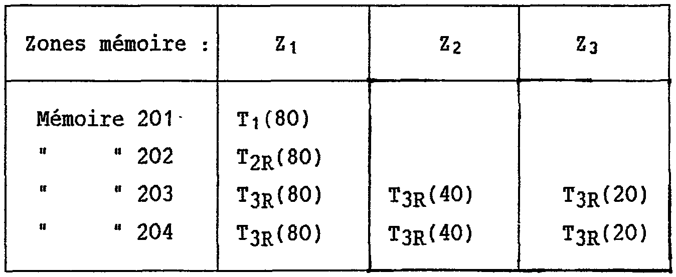
<tb> Memory <SEP> 201 <SEP> Tu (80) <SEP> (1/4) tlR (40) V2 <SEP>
<tb>"<SEP>"<SEP> 202 <SEP> T2R (80) <SEP> (1/4) t1R (40) V2 <SEP> T2R (20)
<tb><SEP>"<SEP>"<SEP> 203 <SEP> T3R (80) <SEP> (1/4) tlR (40) V2 <SEP> - <SEP>
<tb><SEP>"<SEP>"<SEP> 204 <SEP> T4Rt80) <SEP> (1/4) tlR (40) V2 <SEP>
<Tb>
TABLE 8
<tb> Zones <SEP> mémoire <SEP> :<SEP> Z1 <SEP> Z2 <SEP> Z3
<tb> Mémoire <SEP> 201- <SEP> T1(80) <SEP>
<tb> " <SEP> " <SEP> 202 <SEP> T2Rt80) <SEP>
<tb> " <SEP> " <SEP> 203 <SEP> T3R(80) <SEP> T3R(40) <SEP> T3R(20)
<tb> " <SEP> " <SEP> 204 <SEP> T3R(80) <SEP> T3R(40) <SEP> T3R(20)
<tb>
L'indice R indique comme précédemment un retard T pour l'exécution de l'opération accompagnée de cet indice.<tb> Zones <SEP> memory <SEP>: <SEP> Z1 <SEP> Z2 <SEP> Z3
<tb> Memory <SEP> 201- <SEP> T1 (80) <SEP>
<tb>"<SEP>"<SEP> 202 <SEP> T2Rt80) <SEP>
<tb>"<SEP>"<SEP> 203 <SEP> T3R (80) <SEP> T3R (40) <SEP> T3R (20)
<tb>"<SEP>"<SEP> 204 <SEP> T3R (80) <SEP> T3R (40) <SEP> T3R (20)
<Tb>
The index R indicates as previously a delay T for the execution of the operation accompanied by this index.
Pendant la quatrième étape, qui est celle du décodage de la trame D3 et qui est décrite en se référant à la figure 15c, le contenu des mémoires 201 et 204 est lu en synchronisme avc la trame Tq présente maintenant au point C. On obtient alors en D, E, F les informations nécessaires à la reconstitution de la maille 40 ms. Le contenu des mémoires 202 et 203 est lu avec un retard T par rapport au informations d'entrée. Cette lecture et les sorties des lignes à retard L1 et L2 fournissent aux points I, J, Kr L les informations nécessaires aux circuits de reconstitution de maille au premier et au troisième rythme. During the fourth step, which is that of the decoding of the frame D3 and which is described with reference to FIG. 15c, the contents of the memories 201 and 204 are read in synchronism with the frame Tq now present at the point C. in D, E, F the information needed to reconstitute the 40 ms mesh. The contents of the memories 202 and 203 are read with a delay T with respect to the input information. This reading and the outputs of the delay lines L1 and L2 provide the points I, J, Kr L with the information necessary for the circuitry of reconstituting mesh at the first and the third rhythm.
Simultanément, le circuit de compensation de mouvement fournit les termes t3(40) compensés du vecteur V4, qui sont alors mémorisés dans les mémoires 201 à 204. Les informations T1(80), T2(80), T3(80) sont conservées dans les mémoires 201 à 203. Simultaneously, the motion compensation circuit provides the compensated terms t3 (40) of the vector V4, which are then stored in the memories 201 to 204. The information T1 (80), T2 (80), T3 (80) are stored in the memories 201 to 203.
Les tableaux 9 et 10 rassemblent les informations respectivement lues et écrites pendant cette quatrième étape de décodage de la trame D3
TABLEAU 9

TABLE 9
<tb> Zones <SEP> mémoire <SEP> : <SEP> Z1 <SEP> Z2 <SEP> Z3 <SEP>
<tb> <SEP> Mémoire <SEP> 201 <SEP> Ti(80) <SEP>
<tb> <SEP> M <SEP> " <SEP> 202 <SEP> T2R(80)
<tb> <SEP> 203 <SEP> T3R(80) <SEP> T3R(40) <SEP> T3R(20)
<tb> <SEP> " <SEP> " <SEP> 204 <SEP> T3(80) <SEP> T3R(40)
<tb>
TABLEAU 10
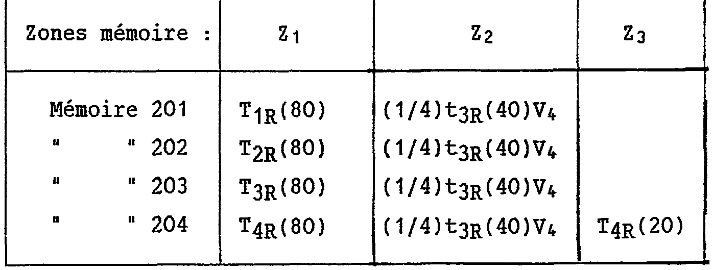
<tb><SEP> Memory <SEP> 201 <SEP> Ti (80) <SEP>
<tb><SEP> M <SEP>"<SEP> 202 <SEP> T2R (80)
<tb><SEP> 203 <SEP> T3R (80) <SEP> T3R (40) <SEP> T3R (20)
<tb><SEP>"<SEP>"<SEP> 204 <SEP> T3 (80) <SEP> T3R (40)
<Tb>
TABLE 10
<tb> Zones <SEP> mémoire <SEP> :<SEP> Z1 <SEP> Z2 <SEP> Z3
<tb> <SEP> Mémoire <SEP> 201 <SEP> T1R(80) <SEP> (1/4)t3R(40)V4
<tb> <SEP> 202 <SEP> T2R(80) <SEP> (114)t3Rt40)V4 <SEP>
<tb> <SEP> 203 <SEP> T3R(80) <SEP> (l/4)t3R(40)V4 <SEP>
<tb> <SEP> 204 <SEP> T4R(80) <SEP> (1/4)t3R(40)V4 <SEP> T4R(20) <SEP>
<tb>
Pendant la cinquième étape, qui est celle du décodage de la trame D4 et qui est décrite en se référant à la figure 15d, ce sont cette fois les trames Ts, Ts, T7 qui sont disponibles aux points C, B, A pour permettre la reconstitution de maille 40 ms.De façon similaire à ce qui a été effectué au cours de la troisième étape, le contenu des mémoires 201 à 204 est lu avec un retard T par rapport aux informations d'entrée.<tb> Zones <SEP> memory <SEP>: <SEP> Z1 <SEP> Z2 <SEP> Z3
<tb><SEP> Memory <SEP> 201 <SEP> T1R (80) <SEP> (1/4) t3R (40) V4
<tb><SEP> 202 <SEP> T2R (80) <SEP> (114) t3Rt40) V4 <SEP>
<tb><SEP> 203 <SEP> T3R (80) <SEP> (l / 4) t3R (40) V4 <SEP>
<tb><SEP> 204 <SEP> T4R (80) <SEP> (1/4) t3R (40) V4 <SEP> T4R (20) <SEP>
<Tb>
During the fifth step, which is that of the decoding of the frame D4 and which is described with reference to FIG. 15d, it is this time the frames Ts, Ts, T7 that are available at the points C, B, A to enable the Replenishment of 40 ms mesh Similar to what was done in the third step, the contents of the memories 201 to 204 is read with a delay T with respect to the input information.
Cette lecture conduit à disposer1 aux points I, J, K, Lr d'une part des termes t3 (40) compensés du vecteur V4 et précédemment mémorisés dans les mémoires 201 à 204, ces termes étant alors envoyés vers l'additionneur 314, et d'autre part des informations nécessaires aux circuits de reconstitution de maille au premier et au troisième rythme.This reading leads to placing, at the points I, J, K, Lr, on the one hand, the compensated terms t3 (40) of the vector V4 and previously stored in the memories 201 to 204, these terms then being sent to the adder 314, and on the other hand information necessary for the circuits of reconstitution of mesh at the first and the third rhythm.
Par ailleurs, de façon tout à fait similaire à ce qui a été fait au cours de la première étape d'initialisation, la trame Ts est mémorisée dans les mémoires 201 et 203 et la trame TS dans les mémoires 202 et 204. Les tableaux 11 et 12 rassemblent les informations respectivement lues et écrites pendant cette cinquième étape de décodage de la trame D4
TABLEAU 11

TABLE 11
<tb> Zones <SEP> mémoire <SEP> :<SEP> Zi <SEP> Z2 <SEP> Z3
<tb> <SEP> Mémoire <SEP> 201 <SEP> T1R(80) <SEP> (1/4) <SEP> t3R(40)V; <SEP>
<tb> <SEP> " <SEP> " <SEP> 202 <SEP> T2R(80) <SEP> (1/4) <SEP> t3R(40)V4
<tb> <SEP> " <SEP> " <SEP> 203 <SEP> T3R(80) <SEP> (1/4) <SEP> t3R(40)V4
<tb> <SEP> " <SEP> " <SEP> 204 <SEP> T4R(80) <SEP> (1/4) <SEP> t3R(40)V4 <SEP> T4R(20)
<tb>
TABLEAU 12
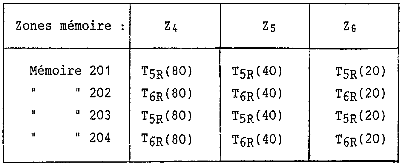
<tb><SEP> Memory <SEP> 201 <SEP> T1R (80) <SEP> (1/4) <SEP> t3R (40) V; <September>
<tb><SEP>"<SEP>"<SEP> 202 <SEP> T2R (80) <SEP> (1/4) <SEP> t3R (40) V4
<tb><SEP>"<SEP>"<SEP> 203 <SEP> T3R (80) <SEP> (1/4) <SEP> t3R (40) V4
<tb><SEP>"<SEP>"<SEP> 204 <SEP> T4R (80) <SEP> (1/4) <SEP> t3R (40) V4 <SEP> T4R (20)
<Tb>
TABLE 12
<tb> Zones <SEP> mémoire <SEP> : <SEP> Z4 <SEP> Z5 <SEP> Zs
<tb> <SEP> Mémoire <SEP> 201 <SEP> T5R(80) <SEP> Tir(40) <SEP> T5R(20)
<tb> <SEP> " <SEP> " <SEP> 202 <SEP> T6R(80) <SEP> T6R(40) <SEP> T6R(20)
<tb> <SEP> " <SEP> " <SEP> 203 <SEP> Tir(80) <SEP> T5R(40) <SEP> Tir(20) <SEP>
<tb> <SEP> " <SEP> " <SEP> 204 <SEP> T6R(80) <SEP> T6R(40) <SEP> T6R(20)
<tb>
On peut maintenant, comme annoncé plus haut, justifier la présence des deux lignes à retard L1 et L2 et le décalage d'une valeur de retard T de l'écriture en mémoire.En se référant à la figure 12, la valeur T correspond à la somme des retards dûs à la restitution de la maille 40 ms (circuit 208), à l'interpolation spatiale (circuit 210), et à la compensation de mouvement (circuit 312). Cette valeur T correspond également au décalage temporel entre les sorties D, E, F et I, J, K, L de l'élément 407, ainsi qu'au décalage temporel entre sa sortie H et ses sorties D, Er F. L'observation des figures 14 et 15a à 15d et des tableaux 5 à 12 montre également que les retards des lignes L1 et L2 et les décalages des lectures et écritures des mémoires 201 à 204 conduisent à un décalage correct entre les sorties D, E, F et les sorties H, I, J, K, L.<tb> Zones <SEP> memory <SEP>: <SEP> Z4 <SEP> Z5 <SEP> Zs
<tb><SEP> Memory <SEP> 201 <SEP> T5R (80) <SEP> Shooting (40) <SEP> T5R (20)
<tb><SEP>"<SEP>"<SEP> 202 <SEP> T6R (80) <SEP> T6R (40) <SEP> T6R (20)
<tb><SEP>"<SEP>"<SEP> 203 <SEP> Shooting (80) <SEP> T5R (40) <SEP> Shooting (20) <SEP>
<tb><SEP>"<SEP>"<SEP> 204 <SEP> T6R (80) <SEP> T6R (40) <SEP> T6R (20)
<Tb>
We can now, as announced above, justify the presence of the two delay lines L1 and L2 and the offset of a delay value T of the memory entry. Referring to FIG. 12, the value T corresponds to the sum of the delays due to the reproduction of the 40 ms mesh (circuit 208), to the spatial interpolation (circuit 210), and to the motion compensation (circuit 312). This value T also corresponds to the time offset between the outputs D, E, F and I, J, K, L of the element 407, as well as the time difference between its output H and its outputs D, Er F. observation of Figures 14 and 15a to 15d and Tables 5 to 12 also shows that the delays of lines L1 and L2 and the shifts of the reads and writes of the memories 201 to 204 lead to a correct shift between the outputs D, E, F and the outputs H, I, J, K, L.
Bien entendu, la présente invention n'est pas limitée aux modes de réalisation décrits et représentés, à partir desquels des variantes peuvent être proposées sans pour cela sortir du cadre de l'invention. Par exemple, dans le cas de la figure 13, des commutateurs notés CI, C2, C3 commandés à la fréquence de trame et prévus dans l'élément 407 de stockage intermédiaire et d'aiguillage assurent, ainsi que le multiplexeur
MUX, aux instants appropriés, l'aiguillage correct des trames reçues circulant à travers cet élément. il est manifeste que ces commutateurs, représentés de façon distincte sur la figure, peuvent être regroupés, de manière fonctionnelle, dans un même circuit de commutation assurant de façon similaire les basculements appropriés vers les mémoires intermédiaires 201 à 204, les lignes à retard L1, L2 et les sorties D, E, F, H, I, J, K, L de l'élément 407. Of course, the present invention is not limited to the embodiments described and shown, from which variants can be proposed without departing from the scope of the invention. For example, in the case of FIG. 13, switches labeled C1, C2, C3 controlled at the frame frequency and provided in the intermediate storage and switching element 407 ensure, as well as the multiplexer
MUX, at appropriate times, the correct routing of received frames flowing through this element. it is obvious that these switches, shown separately in the figure, can be grouped, in a functional manner, in the same switching circuit similarly providing the appropriate switching to the intermediate memories 201 to 204, the delay lines L1, L2 and the outputs D, E, F, H, I, J, K, L of the element 407.
Claims (3)
Priority Applications (1)
| Application Number | Priority Date | Filing Date | Title |
|---|---|---|---|
| FR8913091A FR2652974B1 (en) | 1989-10-06 | 1989-10-06 | DEVICE FOR DECODING TELEVISION SIGNALS. |
Applications Claiming Priority (1)
| Application Number | Priority Date | Filing Date | Title |
|---|---|---|---|
| FR8913091A FR2652974B1 (en) | 1989-10-06 | 1989-10-06 | DEVICE FOR DECODING TELEVISION SIGNALS. |
Publications (2)
| Publication Number | Publication Date |
|---|---|
| FR2652974A1 true FR2652974A1 (en) | 1991-04-12 |
| FR2652974B1 FR2652974B1 (en) | 1994-01-07 |
Family
ID=9386164
Family Applications (1)
| Application Number | Title | Priority Date | Filing Date |
|---|---|---|---|
| FR8913091A Expired - Fee Related FR2652974B1 (en) | 1989-10-06 | 1989-10-06 | DEVICE FOR DECODING TELEVISION SIGNALS. |
Country Status (1)
| Country | Link |
|---|---|
| FR (1) | FR2652974B1 (en) |
Citations (2)
| Publication number | Priority date | Publication date | Assignee | Title |
|---|---|---|---|---|
| EP0322956A1 (en) * | 1987-12-22 | 1989-07-05 | Koninklijke Philips Electronics N.V. | Video encoding and decoding using an adpative filter |
| EP0330279A1 (en) * | 1988-02-23 | 1989-08-30 | Laboratoires D'electronique Philips | Device for the space-time sub-sampling of digital video signals representative of a sequence of interlaced or sequential pictures, system for the transmission of high definition television pictures including such a device, and broadcasting and receiving stages for such a system |
-
1989
- 1989-10-06 FR FR8913091A patent/FR2652974B1/en not_active Expired - Fee Related
Patent Citations (2)
| Publication number | Priority date | Publication date | Assignee | Title |
|---|---|---|---|---|
| EP0322956A1 (en) * | 1987-12-22 | 1989-07-05 | Koninklijke Philips Electronics N.V. | Video encoding and decoding using an adpative filter |
| EP0330279A1 (en) * | 1988-02-23 | 1989-08-30 | Laboratoires D'electronique Philips | Device for the space-time sub-sampling of digital video signals representative of a sequence of interlaced or sequential pictures, system for the transmission of high definition television pictures including such a device, and broadcasting and receiving stages for such a system |
Also Published As
| Publication number | Publication date |
|---|---|
| FR2652974B1 (en) | 1994-01-07 |
Similar Documents
| Publication | Publication Date | Title |
|---|---|---|
| EP0330279B1 (en) | Device for the space-time sub-sampling of digital video signals representative of a sequence of interlaced or sequential pictures, system for the transmission of high definition television pictures including such a device, and broadcasting and receiving stages for such a system | |
| EP0022713B1 (en) | Device for coding and decoding a digital videophone signal | |
| EP0418952B1 (en) | Coding device for bidimensional informations, and decoding device therefor | |
| EP0347325B1 (en) | Method and installation for broadcasting compatible high-definition programmes | |
| FR2600478A1 (en) | METHOD AND DEVICE FOR FREEZING TELEVISION IMAGE | |
| EP0368400B1 (en) | Coding, decoding and transmitting system for television pictures | |
| EP0337565B1 (en) | Device for coding signals representative of a sequence of pictures and system for transmission of high definition television pictures including such a device | |
| FR2650718A1 (en) | DEVICE FOR TRANSFORMING MOTION INFORMATION TO A MOTION DETECTION SIGNAL AT THE FRAME FREQUENCY AND THE NUMBER OF LINES WISHED FOR A HIGH DEFINITION TELEVISION RECEIVER | |
| EP0428216B1 (en) | Device for improved decoding of HD-MAC television signals | |
| EP0404238B1 (en) | Devices for signal processing before and after transmission and/or storage with data rate reduction, and systems for transmitting and/or storing signals including such devices | |
| EP0365090B1 (en) | Device for doubling the sequential rate of television signals, and television picture decoder comprising such a device | |
| FR2652974A1 (en) | Television signal decoding device | |
| EP0350122A1 (en) | Methods and devices for coding and decoding high-definition television pictures, and transmission systems including such devices | |
| FR2646047A1 (en) | Process and installation for coding and transmitting moving pictures in digital form at low speed | |
| FR2489061A1 (en) | Image digital transmission circuit - samples image and transmits selected samples with restoration of omitted samples in receiver | |
| EP0395507B1 (en) | Transmission and reception system for the transmission of moving colour pictures and sound through independent channels | |
| EP0419353B1 (en) | High definition television programmes decoding device | |
| FR2510854A1 (en) | METHOD AND DEVICE FOR RECONSTITUTING A TELEVISION IMAGE FROM A FRAME OF A DIGITAL COMPOSITE SIGNAL | |
| FR2665042A1 (en) | Video signal processing device | |
| FR2633472A1 (en) | Device for temporal sub-sampling and motion-compensated temporal interpolation in an interlaced image sequence, use of such a device in the coding and decoding devices of a high-definition television picture transmission system, and coding and decoding devices for such a system | |
| FR2630283A1 (en) | Device for temporal sub-sampling and motion-compensated temporal interpolation in an interlaced image sequence, use of such a device in the coding/decoding circuits of a high-definition television image transmission system; coding/decoding devices for such a system | |
| FR2651949A1 (en) | METHOD FOR RECORDING AND READING HIGH DEFINITION TELEVISION SIGNALS. | |
| EP0329717A1 (en) | Processor for stereoscopic presentation of video images | |
| FR2638928A1 (en) | Devices for coding and decoding television pictures, television picture transmission system incorporating such devices, and transmission and reception stages of such a system | |
| FR2648650A1 (en) | Device for processing signals intended to be relayed and/or stored after bit-rate reduction, and system for relaying and/or storing signals incorporating such a device in its transmission stage |
Legal Events
| Date | Code | Title | Description |
|---|---|---|---|
| ST | Notification of lapse |