ES2944136T3 - power supply system - Google Patents
power supply system Download PDFInfo
- Publication number
- ES2944136T3 ES2944136T3 ES16916217T ES16916217T ES2944136T3 ES 2944136 T3 ES2944136 T3 ES 2944136T3 ES 16916217 T ES16916217 T ES 16916217T ES 16916217 T ES16916217 T ES 16916217T ES 2944136 T3 ES2944136 T3 ES 2944136T3
- Authority
- ES
- Spain
- Prior art keywords
- voltage
- output
- power supply
- load
- supply system
- Prior art date
- Legal status (The legal status is an assumption and is not a legal conclusion. Google has not performed a legal analysis and makes no representation as to the accuracy of the status listed.)
- Active
Links
Classifications
-
- H—ELECTRICITY
- H02—GENERATION; CONVERSION OR DISTRIBUTION OF ELECTRIC POWER
- H02M—APPARATUS FOR CONVERSION BETWEEN AC AND AC, BETWEEN AC AND DC, OR BETWEEN DC AND DC, AND FOR USE WITH MAINS OR SIMILAR POWER SUPPLY SYSTEMS; CONVERSION OF DC OR AC INPUT POWER INTO SURGE OUTPUT POWER; CONTROL OR REGULATION THEREOF
- H02M7/00—Conversion of AC power input into DC power output; Conversion of DC power input into AC power output
- H02M7/42—Conversion of DC power input into AC power output without possibility of reversal
- H02M7/44—Conversion of DC power input into AC power output without possibility of reversal by static converters
- H02M7/48—Conversion of DC power input into AC power output without possibility of reversal by static converters using discharge tubes with control electrode or semiconductor devices with control electrode
- H02M7/493—Conversion of DC power input into AC power output without possibility of reversal by static converters using discharge tubes with control electrode or semiconductor devices with control electrode the static converters being arranged for operation in parallel
-
- H—ELECTRICITY
- H02—GENERATION; CONVERSION OR DISTRIBUTION OF ELECTRIC POWER
- H02J—ELECTRIC POWER NETWORKS; CIRCUIT ARRANGEMENTS OR SYSTEMS FOR SUPPLYING OR DISTRIBUTING ELECTRIC POWER; SYSTEMS FOR STORING ELECTRIC ENERGY
- H02J9/00—Circuit arrangements for emergency or stand-by power supply, e.g. for emergency lighting
- H02J9/04—Circuit arrangements for emergency or stand-by power supply, e.g. for emergency lighting in which the distribution system is disconnected from the normal source and connected to a standby source
- H02J9/06—Circuit arrangements for emergency or stand-by power supply, e.g. for emergency lighting in which the distribution system is disconnected from the normal source and connected to a standby source with automatic change-over, e.g. UPS systems
- H02J9/062—Circuit arrangements for emergency or stand-by power supply, e.g. for emergency lighting in which the distribution system is disconnected from the normal source and connected to a standby source with automatic change-over, e.g. UPS systems for AC powered loads
-
- H—ELECTRICITY
- H02—GENERATION; CONVERSION OR DISTRIBUTION OF ELECTRIC POWER
- H02M—APPARATUS FOR CONVERSION BETWEEN AC AND AC, BETWEEN AC AND DC, OR BETWEEN DC AND DC, AND FOR USE WITH MAINS OR SIMILAR POWER SUPPLY SYSTEMS; CONVERSION OF DC OR AC INPUT POWER INTO SURGE OUTPUT POWER; CONTROL OR REGULATION THEREOF
- H02M1/00—Details of apparatus for conversion
- H02M1/08—Circuits specially adapted for the generation of control voltages for semiconductor devices incorporated in static converters
-
- H—ELECTRICITY
- H02—GENERATION; CONVERSION OR DISTRIBUTION OF ELECTRIC POWER
- H02M—APPARATUS FOR CONVERSION BETWEEN AC AND AC, BETWEEN AC AND DC, OR BETWEEN DC AND DC, AND FOR USE WITH MAINS OR SIMILAR POWER SUPPLY SYSTEMS; CONVERSION OF DC OR AC INPUT POWER INTO SURGE OUTPUT POWER; CONTROL OR REGULATION THEREOF
- H02M1/00—Details of apparatus for conversion
- H02M1/44—Circuits or arrangements for compensating for electromagnetic interference in converters or inverters
-
- H—ELECTRICITY
- H02—GENERATION; CONVERSION OR DISTRIBUTION OF ELECTRIC POWER
- H02M—APPARATUS FOR CONVERSION BETWEEN AC AND AC, BETWEEN AC AND DC, OR BETWEEN DC AND DC, AND FOR USE WITH MAINS OR SIMILAR POWER SUPPLY SYSTEMS; CONVERSION OF DC OR AC INPUT POWER INTO SURGE OUTPUT POWER; CONTROL OR REGULATION THEREOF
- H02M5/00—Conversion of AC power input into AC power output, e.g. for change of voltage, for change of frequency, for change of number of phases
- H02M5/40—Conversion of AC power input into AC power output, e.g. for change of voltage, for change of frequency, for change of number of phases with intermediate conversion into DC
- H02M5/42—Conversion of AC power input into AC power output, e.g. for change of voltage, for change of frequency, for change of number of phases with intermediate conversion into DC by static converters
- H02M5/44—Conversion of AC power input into AC power output, e.g. for change of voltage, for change of frequency, for change of number of phases with intermediate conversion into DC by static converters using discharge tubes or semiconductor devices to convert the intermediate DC into AC
- H02M5/453—Conversion of AC power input into AC power output, e.g. for change of voltage, for change of frequency, for change of number of phases with intermediate conversion into DC by static converters using discharge tubes or semiconductor devices to convert the intermediate DC into AC using devices of a triode or transistor type requiring continuous application of a control signal
- H02M5/458—Conversion of AC power input into AC power output, e.g. for change of voltage, for change of frequency, for change of number of phases with intermediate conversion into DC by static converters using discharge tubes or semiconductor devices to convert the intermediate DC into AC using devices of a triode or transistor type requiring continuous application of a control signal using semiconductor devices only
- H02M5/4585—Conversion of AC power input into AC power output, e.g. for change of voltage, for change of frequency, for change of number of phases with intermediate conversion into DC by static converters using discharge tubes or semiconductor devices to convert the intermediate DC into AC using devices of a triode or transistor type requiring continuous application of a control signal using semiconductor devices only having a rectifier with controlled elements
-
- H—ELECTRICITY
- H02—GENERATION; CONVERSION OR DISTRIBUTION OF ELECTRIC POWER
- H02M—APPARATUS FOR CONVERSION BETWEEN AC AND AC, BETWEEN AC AND DC, OR BETWEEN DC AND DC, AND FOR USE WITH MAINS OR SIMILAR POWER SUPPLY SYSTEMS; CONVERSION OF DC OR AC INPUT POWER INTO SURGE OUTPUT POWER; CONTROL OR REGULATION THEREOF
- H02M1/00—Details of apparatus for conversion
- H02M1/0003—Details of control, feedback or regulation circuits
- H02M1/0025—Arrangements for modifying reference values, feedback values or error values in the control loop of a converter
-
- H—ELECTRICITY
- H02—GENERATION; CONVERSION OR DISTRIBUTION OF ELECTRIC POWER
- H02M—APPARATUS FOR CONVERSION BETWEEN AC AND AC, BETWEEN AC AND DC, OR BETWEEN DC AND DC, AND FOR USE WITH MAINS OR SIMILAR POWER SUPPLY SYSTEMS; CONVERSION OF DC OR AC INPUT POWER INTO SURGE OUTPUT POWER; CONTROL OR REGULATION THEREOF
- H02M1/00—Details of apparatus for conversion
- H02M1/08—Circuits specially adapted for the generation of control voltages for semiconductor devices incorporated in static converters
- H02M1/081—Circuits specially adapted for the generation of control voltages for semiconductor devices incorporated in static converters wherein the phase of the control voltage is adjustable with reference to the AC source
Landscapes
- Engineering & Computer Science (AREA)
- Power Engineering (AREA)
- Physics & Mathematics (AREA)
- Electromagnetism (AREA)
- Business, Economics & Management (AREA)
- Emergency Management (AREA)
- Inverter Devices (AREA)
- Catching Or Destruction (AREA)
- Vehicle Body Suspensions (AREA)
- Input Circuits Of Receivers And Coupling Of Receivers And Audio Equipment (AREA)
Abstract
Este sistema de suministro de energía está provisto de una pluralidad de convertidores de salida de CA que están conectados en paralelo y que suministran energía a una carga de CA. Cada uno de los convertidores de salida de CA incluye: impedancia de salida que está conectada a la carga de CA; un convertidor PWM que convierte la energía de CC en energía de CA; y un dispositivo de control que emite un valor de comando de voltaje al convertidor PWM. El dispositivo de control incluye: un sumador vectorial que realiza una suma vectorial en una porción de una caída de voltaje causada por una corriente que fluye a través de la impedancia de salida y el valor de comando de voltaje de la carga de CA; y un convertidor que emite el valor de comando de voltaje al convertidor PWM sobre la base de la suma de vectores obtenida a través de la suma de vectores. (Traducción automática con Google Translate, sin valor legal)This power supply system is provided with a plurality of AC output converters that are connected in parallel and supply power to an AC load. Each of the AC output converters includes: output impedance that is connected to the AC load; a PWM converter that converts DC power to AC power; and a control device that outputs a voltage command value to the PWM converter. The control device includes: a vector adder that performs vector addition on a portion of a voltage drop caused by a current flowing through the output impedance and the AC load voltage command value; and a converter that outputs the voltage command value to the PWM converter on the basis of the vector addition obtained through the vector addition. (Automatic translation with Google Translate, without legal value)
Description
DESCRIPCIÓNDESCRIPTION
Sistema de suministro de energíapower supply system
CAMPO TÉCNICOTECHNICAL FIELD
La presente invención se refiere a un sistema de suministro de energía que comprende una pluralidad de convertidores de salida de CA conectados en paralelo para suministrar energía eléctrica a una carga de CA.The present invention relates to a power supply system comprising a plurality of parallel-connected AC output converters for supplying electrical power to an AC load.
TÉCNICA ANTERIORPRIOR ART
Existe un sistema de suministro de energía conocido para suministrar energía eléctrica a una carga a través de una conexión en paralelo de una pluralidad de convertidores de salida de CA, cada uno configurado para realizar la conversión de energía de una corriente continua a una corriente alterna.There is a known power supply system for supplying electrical power to a load through a parallel connection of a plurality of AC output converters, each configured to perform power conversion from direct current to alternating current.
Con respecto a lo anterior, el documento JP H04 - 217 822 A divulga un sistema de suministro de energía en el que una pluralidad de convertidores de salida de CA (como un inversor) están conectados en paralelo y funcionan en paralelo a una carga común.Regarding the above, JP H04-217 822 A discloses a power supply system in which a plurality of AC output converters (such as an inverter) are connected in parallel and operate in parallel to a common load.
Como esquema para controlar el equilibrio de corriente entre una pluralidad de convertidores de salida de CA, el sistema de suministro de energía está configurado para obtener señales de detección de las corrientes de salida de la pluralidad de convertidores de salida de CA para adquirir una señal diferencial de los mismos, controlando así las tensiones de salida de los convertidores de salida de CA de acuerdo con la señal diferencial.As a scheme for controlling the current balance between a plurality of AC output converters, the power supply system is configured to obtain detection signals of the output currents of the plurality of AC output converters to acquire a differential signal. of them, thus controlling the output voltages of the AC output converters according to the differential signal.
El sistema de suministro de energía en el documento JP H04 - 217 822 A emplea un esquema de adquisición de señales de detección de las corrientes de salida de los convertidores de salida de CA para controlar el balance de corriente. Por lo tanto, se hace necesario adquirir información de otros convertidores de salida de CA, lo que requiere que se proporcionen medios de transmisión de señales. Así, un fallo que se produzca en este medio de transmisión de señales puede impedir un control adecuado.The power supply system in JP H04-217 822 A employs a scheme for acquiring detection signals of the output currents of the AC output converters to control the current balance. Therefore, it becomes necessary to acquire information from other AC output converters, which requires signal transmission means to be provided. Thus, a failure that occurs in this signal transmission medium can prevent adequate control.
Además, cuando se separa un convertidor de salida de CA para mantenimiento o cuando se agrega un convertidor de salida de CA para expansión, se hace necesario realizar etapas complicadas de desconectar los medios de transmisión de señales, volver a conectar los medios de transmisión de señales y similares. Esto requiere que se detenga todo el sistema.In addition, when an AC output converter is separated for maintenance or when an AC output converter is added for expansion, it becomes necessary to perform complicated steps of disconnecting the signal transmission means, reconnecting the signal transmission means and the like. This requires the entire system to stop.
Shamseh Mohammad Bani y otros: "A Robust Equal-Load-Sharing Control Scheme for Parallel UPS Units with Time Delay Consideration", 2016 IEEE 8th International Power Electronics and Motion Control Conference (IPEMC-ECCE ASIA), IEEE, 22 de mayo de 2016, páginas 3453-3460, XP032924836 divulga un esquema de control robusto para compartir la carga equitativamente entre n unidades UPS conectadas en paralelo con filtros de salida LCL. El control de lazo doble se usa con retroalimentación de tensión del capacitor en el lazo externo y retroalimentación de corriente del capacitor en el lazo interno. El tiempo de retardo en el intercambio de información entre las unidades UPS se tiene en cuenta en el análisis de estabilidad.Shamseh Mohammad Bani et al: "A Robust Equal-Load-Sharing Control Scheme for Parallel UPS Units with Time Delay Consideration", 2016 IEEE 8th International Power Electronics and Motion Control Conference (IPEMC-ECCE ASIA), IEEE, May 22, 2016 , pages 3453-3460, XP032924836 discloses a robust control scheme to share the load equally among n parallel connected UPS units with LCL output filters. Dual loop control is used with capacitor voltage feedback on the outer loop and capacitor current feedback on the inner loop. The time delay in the exchange of information between the UPS units is taken into account in the stability analysis.
El documento JP 2009 141 997 A se refiere a un sistema de control de operación en paralelo para realizar una operación en paralelo con la misma carga compartida entre una pluralidad de convertidores de energía. Por esa razón, cada dispositivo de conversión de energía incluye un convertidor de energía y un dispositivo de control. Para calcular una referencia de tensión del convertidor de energía, se resta a la referencia de tensión un producto de una corriente de salida y una resistencia virtual.JP 2009 141 997 A relates to a parallel operation control system for performing parallel operation with the same load sharing among a plurality of power converters. For that reason, each power conversion device includes a power converter and a control device. To calculate a power converter voltage reference, a product of an output current and a virtual resistance is subtracted from the voltage reference.
Un objeto de la presente invención es resolver los problemas descritos anteriormente e implementar un sistema de suministro de energía capaz de equilibrar corrientes entre una pluralidad de convertidores de salida de CA mientras controla la pluralidad de convertidores de salida de CA de forma independiente.An object of the present invention is to solve the problems described above and implement a power supply system capable of balancing currents between a plurality of AC output converters while controlling the plurality of AC output converters independently.
Este objeto se resuelve mediante un sistema de suministro de energía como se define en la reivindicación independiente 1. Las realizaciones preferidas son objeto de las reivindicaciones dependientes.This object is solved by a power supply system as defined in independent claim 1. Preferred embodiments are the subject of the dependent claims.
EFECTOS VENTAJOSOS DE LA INVENCIÓNADVANTAGEOUS EFFECTS OF THE INVENTION
El sistema de suministro de energía de la presente invención es capaz de equilibrar las corrientes entre una pluralidad de convertidores de salida de CA mientras controla la pluralidad de convertidores de salida de CA de forma independiente.The power supply system of the present invention is capable of balancing currents between a plurality of AC output converters while controlling the plurality of AC output converters independently.
BREVE DESCRIPCIÓN DE LOS DIBUJOSBRIEF DESCRIPTION OF THE DRAWINGS
La figura 1 es un diagrama que ilustra la configuración de un sistema de alimentación ininterrumpida 1 según la primera forma de realización. Fig. 1 is a diagram illustrating the configuration of an uninterruptible power supply 1 according to the first embodiment.
La figura 2 es un diagrama que ilustra la configuración de un convertidor de salida de CA 10 de un circuito trifásico según la primera realización.Fig. 2 is a diagram illustrating the configuration of an AC output converter 10 of a three-phase circuit according to the first embodiment.
La figura 3 es un diagrama que muestra esquemáticamente el sistema de alimentación ininterrumpida 1 según la primera forma de realización.Fig. 3 is a diagram schematically showing the uninterruptible power supply 1 according to the first embodiment.
La figura 4 es un diagrama que ilustra un circuito equivalente según la primera realización.Fig. 4 is a diagram illustrating an equivalent circuit according to the first embodiment.
La figura 5 es un diagrama que ilustra el estado inicial del sistema de suministro de energía ininterrumpible 1 según la primera realización.Fig. 5 is a diagram illustrating the initial state of the uninterruptible power supply system 1 according to the first embodiment.
La figura 6 es un diagrama que ilustra el estado inmediatamente después de que se cierra un interruptor del sistema de suministro de energía ininterrumpible 1 de acuerdo con la primera realización.Fig. 6 is a diagram illustrating the state immediately after a switch of the uninterruptible power supply system 1 is closed according to the first embodiment.
La figura 7 es un diagrama que ilustra el resultado de la simulación del sistema de suministro de energía ininterrumpible 1 según la primera realización.Fig. 7 is a diagram illustrating the simulation result of the uninterruptible power supply system 1 according to the first embodiment.
La figura 8 es un diagrama que ilustra la configuración de un sistema de alimentación ininterrumpida 1P según la primera modificación de la primera realización.Fig. 8 is a diagram illustrating the configuration of a 1P uninterruptible power supply according to the first modification of the first embodiment.
La figura 9 es un diagrama que ilustra la configuración de un sistema de alimentación ininterrumpida 1Q según la segunda modificación de la primera realización.Fig. 9 is a diagram illustrating the configuration of an uninterruptible power supply 1Q according to the second modification of the first embodiment.
La figura 10 es un diagrama que ilustra la configuración de un sistema de alimentación ininterrumpida 1# según la segunda realización.Fig. 10 is a diagram illustrating the configuration of a 1# uninterruptible power supply according to the second embodiment.
La figura 11 es un diagrama que ilustra la configuración de un circuito de generación de valor nominal de tensión de condensador 52A según la segunda realización.Fig. 11 is a diagram illustrating the configuration of a capacitor voltage rating generating circuit 52A according to the second embodiment.
La figura 12 es un diagrama que ilustra la configuración de un circuito de control de tensión de capacitor 55A de acuerdo con la segunda realización.Fig. 12 is a diagram illustrating the configuration of a capacitor voltage control circuit 55A according to the second embodiment.
La figura 13 es un diagrama que muestra esquemáticamente el sistema de alimentación ininterrumpida 1# según la segunda realización.Fig. 13 is a diagram schematically showing the uninterruptible power supply 1# according to the second embodiment.
La figura 14 es un diagrama que ilustra un circuito equivalente según la segunda realización.Fig. 14 is a diagram illustrating an equivalent circuit according to the second embodiment.
La figura 15 es un diagrama que ilustra otro circuito equivalente según la segunda realización.Fig. 15 is a diagram illustrating another equivalent circuit according to the second embodiment.
La figura 16 es un diagrama que ilustra el resultado de la simulación del sistema de suministro de energía ininterrumpible 1# de acuerdo con la segunda realización.Fig. 16 is a diagram illustrating the simulation result of the uninterruptible power supply system 1# according to the second embodiment.
La figura 17 es un diagrama que ilustra la configuración de un sistema de alimentación ininterrumpida 1#P según la primera modificación de la segunda realización.Fig. 17 is a diagram illustrating the configuration of an uninterruptible power supply 1#P according to the first modification of the second embodiment.
La figura 18 es un diagrama que ilustra la configuración de un sistema de alimentación ininterrumpida 1#Q según la segunda modificación de la segunda realización.Fig. 18 is a diagram illustrating the configuration of an uninterruptible power supply 1#Q according to the second modification of the second embodiment.
La figura 19 es un diagrama que muestra esquemáticamente la configuración de un sistema de suministro de energía ininterrumpible según la tercera realización.Fig. 19 is a diagram schematically showing the configuration of an uninterruptible power supply system according to the third embodiment.
La figura 20 es un diagrama que ilustra el resultado de la simulación de un sistema de suministro de energía ininterrumpible 1# según la tercera realización.Fig. 20 is a diagram illustrating the simulation result of a 1# uninterruptible power supply system according to the third embodiment.
DESCRIPCIÓN DE REALIZACIONESDESCRIPTION OF EMBODIMENTS
A continuación, se describirán las realizaciones con referencia a los dibujos adjuntos. En el presente ejemplo, un sistema de suministro de energía ininterrumpible (en lo sucesivo abreviado como UPS) se describirá como un sistema de suministro de energía a modo de ejemplo.In the following, the embodiments will be described with reference to the accompanying drawings. In the present example, an uninterruptible power supply system (hereinafter abbreviated as UPS) will be described as an exemplary power supply system.
Primera RealizaciónFirst Realization
En la presente realización, el sistema de alimentación ininterrumpida se describirá con referencia a una configuración en paralelo de dos convertidores de salida de CA.In the present embodiment, the uninterruptible power supply will be described with reference to a parallel configuration of two AC output converters.
La figura 1 es un diagrama que ilustra la configuración de un sistema de alimentación ininterrumpida 1 según la primera forma de realización.Fig. 1 is a diagram illustrating the configuration of an uninterruptible power supply 1 according to the first embodiment.
Haciendo referencia a la figura 1, el sistema de alimentación ininterrumpida 1 incluye un convertidor de salida de CA (el primer convertidor de salida de CA) 10A y un convertidor de salida de CA (el segundo convertidor de salida de CA) 10B. Los convertidores de salida de CA 10A y 10B (que también se denominarán colectivamente convertidor de salida de CA 10) están conectados a una fuente de alimentación de CA 2 y funcionan en paralelo con una carga común 3. Referring to Fig. 1, the uninterruptible power supply 1 includes an AC output converter (the first AC output converter) 10A and an AC output converter (the second AC output converter) 10B. AC output converters 10A and 10B (which will also be collectively referred to as AC output converter 10) are connected to an AC power source 2 and operate in parallel with a common load 3.
Los convertidores de salida de CA 10A y 10B según la presente primera realización realizan un control autónomo sin entrada de los medios de transmisión de señales desde el convertidor de salida de CA del otro.The AC output converters 10A and 10B according to the present first embodiment perform autonomous control without input of the signal transmission means from the AC output converter of the other.
A continuación, se describirá la configuración de cada uno de los convertidores de salida de CA 10A y 10B.Next, the configuration of each of the AC output converters 10A and 10B will be described.
El convertidor de salida de CA 10A incluye un transformador 12A, un rectificador 14A configurado para convertir una tensión de CA en una tensión de CC, un capacitor de CC 15A, un convertidor de modulación de ancho de pulso (PWM) 16A, una impedancia de salida 17A y un controlador 20A.The 10A AC output converter includes a 12A transformer, a 14A rectifier configured to convert an AC voltage to a DC voltage, a 15A DC capacitor, a 16A Pulse Width Modulation (PWM) converter, an impedance of 17A outlet and a 20A controller.
En la etapa posterior al rectificador 14A, se proporciona un condensador de CC 15A para mantener la tensión de CC aproximadamente constante. El rectificador 14A y el condensador de CC 15A forman un circuito de CC. In the stage after the rectifier 14A, a DC capacitor 15A is provided to keep the DC voltage approximately constant. The 14A rectifier and the 15A DC capacitor form a DC circuit.
También en el presente ejemplo, el circuito de CC está conectado a una batería, aunque no se muestra. Por lo tanto, se puede suministrar energía eléctrica desde la batería a una carga en caso de pérdida de la fuente de alimentación de CA.Also in the present example, the DC circuit is connected to a battery, although it is not shown. Thus, electrical power can be supplied from the battery to a load in the event of loss of the AC power source.
En el estado normal, la energía eléctrica de la fuente de alimentación de CA 2 se obtiene a través del rectificador 14A y se convierte en tensión de CC.In the normal state, the electric power from the AC power supply 2 is obtained through the rectifier 14A and is converted into DC voltage.
Además, el convertidor PWM 16A está conectado a la etapa siguiente al condensador de CC 15A.In addition, the 16A PWM converter is connected to the next stage to the 15A DC capacitor.
El convertidor PWM 16A convierte la energía de CC en energía de CA de acuerdo con las señales de puerta del controlador 20A.The 16A PWM converter converts DC power to AC power according to the gate signals of the 20A controller.
En el presente ejemplo, el circuito principal del convertidor de salida de CA se simplifica, pero en muchos casos se forma en un circuito trifásico.In the present example, the main circuit of the AC output converter is simplified, but in many cases it is formed in a three-phase circuit.
El convertidor de salida de CA 10B es básicamente idéntico en configuración al convertidor de salida de CA 10A. El convertidor de salida CA 10B incluye un transformador 12B, un rectificador 14B configurado para convertir una tensión CA en una tensión CC, un condensador CC 15B, un convertidor PWM 16B, una impedancia de salida 17B y un controlador 20B.The AC output converter 10B is basically identical in configuration to the AC output converter 10A. The AC output converter 10B includes a transformer 12B, a rectifier 14B configured to convert an AC voltage to a DC voltage, a DC capacitor 15B, a PWM converter 16B, an output impedance 17B, and a controller 20B.
La impedancia de salida está formada por un reactor.The output impedance is formed by a reactor.
La figura 2 es un diagrama que ilustra la configuración de un convertidor 10 de salida de CA de un circuito trifásico según la primera realización.Fig. 2 is a diagram illustrating the configuration of an AC output converter 10 of a three-phase circuit according to the first embodiment.
La figura 2 muestra el rectificador 14A que incluye: una pluralidad de (seis) elementos de conmutación (por ejemplo, IGBT); y elementos semiconductores formados por diodos conectados en antiparalelo a los mismos. Los elementos de conmutación están conectados en puente.Figure 2 shows rectifier 14A including: a plurality of (six) switching elements (eg, IGBTs); and semiconductor elements formed by diodes connected in antiparallel to them. The switching elements are bridged.
Además, el convertidor PWM 16A está provisto de una pluralidad de (seis) elementos de conmutación (por ejemplo, IGBT) y elementos semiconductores formados por diodos conectados en antiparalelo a los mismos.In addition, the PWM converter 16A is provided with a plurality of (six) switching elements (eg, IGBTs) and semiconductor elements formed by diodes connected in antiparallel thereto.
Los elementos de conmutación se controlan para que estén ACTIVADOS y DESACTIVADOS de acuerdo con la señal de puerta del controlador 20A.The switching elements are controlled to be ON and OFF in accordance with the gate signal from the controller 20A.
Para simplificar la explicación, el presente ejemplo se describirá con referencia a un diagrama unifilar y un diagrama fasorial (vectorial) mediante los cuales se puede representar colectivamente un circuito trifásico.For simplicity of explanation, the present example will be described with reference to a one-line diagram and a phasor (vector) diagram by which a three-phase circuit can be collectively represented.
Refiriéndose nuevamente a la figura 1, el controlador 20A incluye un detector de tensión 21A, un circuito de generación de señal de fase de referencia 22A (un circuito PLL), una función de transformación dq 23A, un vector multiplicador 24A, una función de ganancia 25A, un vector sumador 26A, una función de transformación dq inversa 27A, un generador de impulsos PWM 28, registros 29A, 30A y un detector de corriente 31A.Referring again to Figure 1, controller 20A includes a voltage detector 21A, a reference phase signal generation circuit 22A (a PLL circuit), a dq transform function 23A, a multiplier vector 24A, a gain function 25A, a vector adder 26A, an inverse dq transform function 27A, a PWM pulse generator 28, registers 29A, 30A and a current detector 31A.
El circuito de generación de señal de fase de referencia 22A genera una señal de fase de referencia según una señal de detección de tensión procedente del detector de tensión 21A.The reference phase signal generating circuit 22A generates a reference phase signal according to a voltage detection signal from the voltage detector 21A.
El circuito de generación de señal de fase de referencia 22A envía una señal de fase de referencia a la función de transformación dq 23A.The reference phase signal generation circuit 22A outputs a reference phase signal to the dq transform function 23A.
Además, la función de transformación dq 23A recibe una entrada de la señal de detección de corriente del detector de corriente 31A.In addition, the dq transform function 23A receives a current detection signal input from the current detector 31A.
Luego, la función de transformación dq 23A calcula la amplitud y la fase de la corriente basándose en la señal de fase de referencia y la señal de detección de corriente del detector de corriente 31A, para obtener información vectorial sobre la corriente.Then, the dq transform function 23A calculates the amplitude and phase of the current based on the reference phase signal and the current detection signal of the current detector 31A, to obtain vector information about the current.
El método de transformación dq es un método de transformación para obtener un componente de corriente del eje d en sincronización con la señal de fase de referencia y un componente de corriente del eje q desplazado 90 grados en función de la señal de valor instantáneo actual.The dq transformation method is a transformation method for obtaining a d-axis current component in synchronization with the reference phase signal and a q-axis current component shifted by 90 degrees based on the current instantaneous value signal.
El multiplicador vectorial 24A calcula un producto vectorial del valor de la impedancia de salida (Z1 valor de ajuste) almacenado en el registro 29A con respecto a la información vectorial obtenida por la función de transformación dq 23A.The vector multiplier 24A calculates a vector product of the output impedance value (Z1 setting value) stored in the register 29A with respect to the vector information obtained by the dq transform function 23A.
La función de ganancia 25A multiplica el producto vectorial obtenido del multiplicador vectorial 24A por la ganancia correspondiente a un coeficiente ki. El sumador vectorial 26A realiza la suma vectorial de la salida de la función de ganancia 25A y el valor de referencia de la tensión de carga (valor de ajuste Eren) almacenado en el registro 30A. La referencia de tensión de carga es una tensión requerida por la carga y normalmente es una tensión nominal de la misma, pero no se limita a ello y puede establecerse en un valor mayor o menor que la tensión nominal.The gain function 25A multiplies the vector product obtained from the vector multiplier 24A by the gain corresponding to a coefficient ki. The vector adder 26A performs the vector addition of the output of the gain function 25A and the load voltage reference value (setting value Eren) stored in the register 30A. The load voltage reference is a voltage required by the load and is usually a nominal voltage of the load, but it is not limited to it and can be set to a value higher or lower than the nominal voltage.
En el presente ejemplo, se describirá la configuración que incluye el registro 30A. Sin embargo, sin limitarse a un registro, se puede emplear cualquier medio de almacenamiento capaz de almacenar información, y la información también se puede almacenar en una memoria. Lo mismo también se aplica a otras configuraciones.In the present example, the configuration including the register 30A will be described. However, without being limited to a record, any storage medium capable of storing information can be used, and the information can also be stored in a memory. The same also applies to other settings.
El sumador de vectores 26A genera la suma de vectores obtenida a través de la suma de vectores como un comando de tensión de carga.The vector adder 26A generates the vector addition obtained through the vector addition as a charge voltage command.
Luego, la función de transformación dq inversa 27A realiza la transformación dq inversa del comando de tensión de carga del sumador vectorial 26A para generar una referencia de tensión. El generador de pulsos PWM 28A controla la tensión de salida del convertidor PWM 16A según la referencia de tensión obtenida por la transformación inversa dq.Then, the inverse dq transform function 27A performs the inverse dq transform of the charge voltage command of the vector adder 26A to generate a voltage reference. The PWM 28A pulse generator controls the output voltage of the PWM 16A converter according to the voltage reference obtained by the inverse dq transformation.
Dado que el controlador 20B es el mismo que el controlador 20A, no se repetirá la descripción detallada del mismo. A continuación, se describirá el efecto del convertidor de salida de CA según la primera realización.Since the controller 20B is the same as the controller 20A, the detailed description thereof will not be repeated. Next, the effect of the AC output converter according to the first embodiment will be described.
La figura 3 es un diagrama que muestra esquemáticamente el sistema de alimentación ininterrumpida 1 según la primera forma de realización.Fig. 3 is a diagram schematically showing the uninterruptible power supply 1 according to the first embodiment.
Como se muestra en la figura 3, el sistema de alimentación ininterrumpida 1 está formado por convertidores de salida de CA 10A y 10B conectados en paralelo a la carga común 3.As shown in figure 3, the uninterruptible power supply 1 is made up of AC output converters 10A and 10B connected in parallel to the common load 3.
El convertidor PWM 16A y el control del mismo se representan como una fuente de tensión equivalente Eren, y la configuración de la fuente de tensión Eren y una impedancia de salida (Z1) conectados en serie se muestra esquemáticamente.The 16A PWM converter and control thereof are represented as an equivalent voltage source Eren, and the configuration of the voltage source Eren and an output impedance (Z1) connected in series is shown schematically.
De manera similar, también en el convertidor de salida de CA 10B, el convertidor PWM 16 y el control del mismo se representan como una fuente de tensión equivalente Ereti, y la configuración de una fuente de tensión Eren y una impedancia de salida (Z2) conectados en serie se muestra esquemáticamente.Similarly, also in the AC output converter 10B, the PWM converter 16 and the control thereof are represented as an equivalent voltage source Ereti, and the configuration of a voltage source Eren and an output impedance (Z2) connected in series is shown schematically.
El controlador 20A hace que la función de transformación dq 23 realice la transformación dq de la corriente que fluye a través de la impedancia de salida 17A (Z1) para obtener información vectorial I1 sobre la corriente El multiplicador vectorial 24A realiza la multiplicación vectorial de este vector actual y la impedancia Z1 para obtener un producto vectorial Z1I1. También a modo de ejemplo, la función de ganancia 25A se utiliza aquí como medio para obtener una parte del producto vectorial para multiplicar un coeficiente escalar k menor que uno y el producto vectorial para obtener así k rZ rl1. El sumador vectorial 26 realiza la suma vectorial de un comando de tensión de carga EretL, a k rZ rl1 , obteniendo así un valor de comando de tensión Eren del convertidor de salida de CA 10A. El valor de comando de tensión está representado por la siguiente ecuación (1).The controller 20A causes the dq transform function 23 to perform the dq transform of the current flowing through the output impedance 17A (Z1) to obtain vector information I1 about the current. The vector multiplier 24A performs the vector multiplication of this vector current and impedance Z 1 to obtain a vector product Z1I1. Also by way of example, the gain function 25A is used here as a means of obtaining a part of the cross product to multiply a scalar coefficient k less than one and the cross product to thereby obtain k rZ rl1 . The vector adder 26 performs vector addition of a load voltage command EretL, ak rZ rl1 , thereby obtaining a voltage command value Eren of the AC output converter 10A. The voltage command value is represented by the following equation (1).

De manera similar, se obtiene el valor de comando de tensión del convertidor de salida de CA 10B. El valor de comando de tensión está representado por la siguiente ecuación (2). En la ecuación (2), I2 muestra una corriente que fluye a través de una impedancia de salida Z2 del convertidor de salida de CA 10B. El convertidor de salida de CA 10b emplea un coeficiente de ganancia k2.Similarly, the voltage command value of the AC output converter 10B is obtained. The voltage command value is represented by the following equation (2). In equation (2), I2 shows a current flowing through an output impedance Z2 of the AC output converter 10B. The AC output converter 10b employs a gain coefficient k2.

Por otro lado, un circuito eléctrico real está constituido por una fuente de tensión AC formada por un convertidor PWM, una impedancia de salida y una carga, como se muestra en la figura 2.On the other hand, a real electrical circuit is constituted by an AC voltage source formed by a PWM converter, an output impedance and a load, as shown in figure 2.
Suponiendo que la tensión de carga se define como Vl, la ecuación tensión/corriente del circuito eléctrico está representada por la siguiente ecuación. En este caso, se supone que el convertidor PWM está idealmente controlado, de modo que la tensión de salida real sea igual al valor del comando de tensión sin demora ni error. Assuming that the load voltage is defined as V l , the voltage/current equation of the electrical circuit is represented by the following equation. In this case, it is assumed that the PWM converter is ideally controlled so that the actual output voltage is equal to the voltage command value without delay or error.

En este caso, suponiendo que la impedancia de la carga se define como Zl, tensión de carga Vl está representado por la siguiente ecuación.In this case, assuming that the impedance of the load is defined as Zl, load voltage Vl is represented by the following equation.

Cuando el lado izquierdo de la ecuación (3) se reemplaza por el lado derecho de la ecuación (1), se obtiene la siguiente ecuación.When the left side of equation (3) is replaced by the right side of equation (1), the following equation is obtained.

Cuando se convierte la ecuación anterior, se obtiene la siguiente ecuación (7).When the above equation is converted, the following equation (7) is obtained.

Lo mismo se aplica también a la ecuación (4) del convertidor de salida de CA 10B para obtener así la siguiente ecuación.The same is also applied to the equation (4) of the AC output converter 10B to thus obtain the following equation.

Las ecuaciones (3) y (4) están representadas por un circuito equivalente en el que se suministra corriente a una carga desde una fuente de alimentación de CA ErefL a través de un circuito paralelo que incluye dos impedancias de salida equivalentes de (1-k-i)Z1 y 1-k2)Z2, como se muestra en la figura 3.Equations (3) and (4) are represented by an equivalent circuit in which current is supplied to a load from an AC power source ErefL through a parallel circuit that includes two equivalent output impedances of (1-ki )Z1 and 1-k2)Z2, as shown in Figure 3.
La figura 4 es un diagrama que ilustra un circuito equivalente según la primera realización.Fig. 4 is a diagram illustrating an equivalent circuit according to the first embodiment.
Con referencia a la figura 4, se muestra un circuito equivalente de acuerdo con las ecuaciones (7) y (8) anteriores. La relación de distribución de las corrientes I1 y I2, suministradas a la carga 3 desde los convertidores de salida de CA 10A y 10B está determinada por la relación de las impedancias de salida equivalentes.Referring to Fig. 4, an equivalent circuit is shown according to equations (7) and (8) above. The distribution ratio of the currents I1 and I2, supplied to the load 3 from the AC output converters 10A and 10B is determined by the ratio of the equivalent output impedances.
Específicamente, cuando las ecuaciones (7) y (8) se convierten de modo que los lados derechos de las ecuaciones (7) y (8) sean iguales, se obtiene la siguiente ecuación.Specifically, when equations (7) and (8) are converted so that the right-hand sides of equations (7) and (8) are equal, the following equation is obtained.

Con base en la relación anterior, la proporción de participación de I1 y I2 está representado por la siguiente ecuación.Based on the above relationship, the share ratio of I 1 and I 2 is represented by the following equation.

Cuando los convertidores de salida de CA 10A y 10B están formados por el mismo tipo de circuito, el resultado es Z1 = Z2. Además, suponiendo que el coeficiente utilizado en el control es igual, en cuyo caso k1 = k2 , resulta que las corrientes suministradas desde dos convertidores de salida de CA 10A y 10B a la carga 3 se comparten por igual en el estado estable, lo que da como resultado I1 = I2.When the AC output converters 10A and 10B are formed by the same type of circuit, the result is Z1 = Z2. Furthermore, assuming that the coefficient used in the control is equal, in which case k1 = k2 , it follows that the currents supplied from two AC output converters 10A and 10B to load 3 are shared equally in the steady state, which returns I1 = I2.
Como se describió anteriormente, mediante el uso de controladores 20A y 20B según la realización de la presente invención, las corrientes en dos convertidores de salida de CA 10A y 10B pueden equilibrarse o compartirse según corresponda.As described above, by using controllers 20A and 20B according to the embodiment of the present invention, the currents in two AC output converters 10A and 10B can be balanced or shared accordingly.
Dado que se produce un retraso en el control real, lleva algún tiempo alcanzar el estado estacionario descrito anteriormente, que se describirá específicamente a continuación.Since there is a delay in actual control, it takes some time to reach the steady state described above, which will be specifically described below.
Para simplificar la explicación, se supone que los convertidores de salida de CA 10A y 10B tienen la misma impedancia de salida Z y se controlan usando el mismo coeficiente k. To simplify the explanation, it is assumed that the AC output converters 10A and 10B have the same output impedance Z and are controlled using the same coefficient k.
En el estado en el que el convertidor de salida de CA 10A suministra toda la corriente a la carga 3 como estado inicial, se cierra un interruptor SW para que se conecte el convertidor de salida de CA 10B, lo que posteriormente conduce a un aumento gradual en la corriente de salida del convertidor de salida de CA 10A, de modo que la corriente sea equilibrada, lo que se describirá más adelante específicamente. In the state that the AC output converter 10A supplies all the current to the load 3 as the initial state, a switch SW is closed so that the AC output converter 10B is turned on, which subsequently leads to a gradual increase into the output current of the converter output AC 10A, so that the current is balanced, which will be described later specifically.
La figura 5 es un diagrama que ilustra el estado inicial del sistema de suministro de energía ininterrumpible 1 según la primera realización.Fig. 5 is a diagram illustrating the initial state of the uninterruptible power supply system 1 according to the first embodiment.
La figura 5 (A) muestra un diagrama de circuito equivalente en el estado inicial.Figure 5(A) shows an equivalent circuit diagram in the initial state.
La figura 5 (B) muestra un diagrama vectorial (diagrama fasorial) en el estado inicial.Figure 5(B) shows a vector diagram (phasor diagram) in the initial state.
El diagrama vectorial se ilustra asumiendo que la impedancia de salida es un reactor y la impedancia de salida está formada principalmente por una inductancia.The vector diagram is illustrated assuming that the output impedance is a reactor and the output impedance is made up primarily of an inductance.
Además, la carga se representa como una resistencia R de factor de energía unitario.Also, the load is represented as a resistance R of unity power factor.
La ecuación de la corriente y la tensión antes de que se cierre el interruptor SW está representada por la siguiente ecuación.The equation of current and voltage before switch SW is closed is represented by the following equation.

La referencia de tensión del convertidor de salida de CA está representada por la siguiente ecuación ya que la corriente de salida es cero (0).The AC output converter voltage reference is represented by the following equation since the output current is zero (0).

Cuando el interruptor SW está cerrado, los convertidores de salida de CA 10A y 10B deben conectarse como fuentes de tensión a la carga.When the switch SW is closed, the AC output converters 10A and 10B should be connected as voltage sources to the load.
En este momento, la tensión de carga y la corriente compartida cambian. Suponiendo que la tensión de carga cambiado se define como V'l y las corrientes de los convertidores de salida de CA se definen como h' yAt this time, the charging voltage and shared current change. Assuming that the switched load voltage is defined as V'l and the currents of the AC output converters are defined as h' and
T<T<
, se establece la siguiente ecuación. Cabe señalar que las referencias de tensión Eren y Eren no cambie ya que se produce un retraso en el control., the following equation is established. It should be noted that the voltage references Eren and Eren do not change as a control delay occurs.

La suma de las ecuaciones (14) y (15) conduce a la siguiente ecuación.The sum of equations (14) and (15) leads to the following equation.

Con base en la ecuación (16),Based on equation (16),

se sustituye en la ecuación anterior (17) y se ordena, lo que lleva a la siguiente ecuación.is substituted into the above equation (17) and sorted, leading to the following equation.

j ’j ’
La corriente del convertidor de salida de CA 10B se obtiene dividiendo la diferencia entre la tensión de carga cambiado V'l y fuente de tensión Eren por la impedancia. The current of the AC output converter 10B is obtained by dividing the difference between the switched load voltage V'l and source voltage Eren by the impedance.

En este caso, el vector de la tensión de carga es aproximado al vector de referencia de la tensión de carga. Por lo tanto, se considera que la corriente de carga no cambia significativamente de un valor inicial Ii antes y después de que se cierre el interruptor SW. En otras palabras, desdeIn this case, the load voltage vector is approximated to the load voltage reference vector. Therefore, it is considered that the load current does not change significantly from an initial value Ii before and after the switch SW is closed. In other words, from

se supone establecido, una corriente Í 2 se obtiene mediante la siguiente ecuación aproximada.is assumed to be established, a current Í 2 is obtained by the following approximate equation.

En este caso, 1 - k > 0 se establece. Así, una corriente h es tener un valor finito distinto de cero (0).In this case, 1 - k > 0 is set. Thus a current h is to have a finite non-zero value (0).
Dado que la corriente debe suministrarse desde el convertidor de salida de CA 10B a la carga 3, la corriente j 1 Since current must be supplied from AC output converter 10B to load 3, current j 1
Ji del convertidor de salida de CA 10A disminuye de h. Ji of the 10A AC output converter decreases from h.
Tras un lapso de la operación demora en el control, nueva E'rei2 del convertidor de salida de CA 10B se vuelve a J ’ After a lapse of control operation delay, new E'rei 2 AC output converter 10B turns to J'
calcular mediante el aumento de la corriente 2, lo que da como resultado un vector que tiene una fase ligeramente adelantada de Een = E f en el estado inicial.Calculate by increasing the current 2, which results in a vector that has a slightly leading phase of Ein = Ef in the initial state.
Dado que la referencia de tensión E’ren del convertidor de salida de CA 10A se vuelve a calcular utilizando la corriente T’ Since the voltage reference E'ren of the 10A AC output converter is recalculated using the current T'
reducida , muestra un vector retrasado desde el estado inicial.reduced , shows a lagging vector from the initial state.
La figura 6 es un diagrama que ilustra el estado inmediatamente después de que se cierra el interruptor del sistema de alimentación ininterrumpida 1 según la primera realización.Fig. 6 is a diagram illustrating the state immediately after the switch of the uninterruptible power supply 1 is closed according to the first embodiment.
La figura 6 (A) muestra un diagrama de circuito equivalente en el estado inmediatamente posterior al cierre del interruptor.Figure 6(A) shows an equivalent circuit diagram in the state immediately after the switch is closed.
La figura 6 (B) muestra un diagrama vectorial (diagrama fasorial) en el estado en el que el interruptor está cerrado. Tal movimiento se repite. Luego, en el momento en que la referencia de tensión E'ref2 del convertidor de salida de CA 10B se vuelve igual a la referencia de tensión EWi del convertidor de salida de CA 10A, las corrientes de los convertidores de salida de CA 10A y 10B se equilibran para alcanzar el estado estable.Figure 6(B) shows a vector diagram (phasor diagram) in the state in which the switch is closed. Such movement is repeated. Then, at the time when the voltage reference E'ref2 of the AC output converter 10B becomes equal to the voltage reference EWi of the AC output converter 10A, the currents of the AC output converters 10A and 10B equilibrate to reach steady state.
La figura 7 es un diagrama que ilustra el resultado de la simulación del sistema de suministro de energía ininterrumpible 1 según la primera realización.Fig. 7 is a diagram illustrating the simulation result of the uninterruptible power supply system 1 according to the first embodiment.
La figura 7 (A) muestra valores instantáneos de las corrientes de salida de los convertidores de salida de CA 10A y 10B.Fig. 7(A) shows instantaneous values of the output currents of the AC output converters 10A and 10B.
La figura 7 (B) muestra formas de onda de los componentes en paralelo a las tensiones de referencia de carga de las corrientes de salida de los convertidores de salida de CA 10A y 10B.Fig. 7(B) shows waveforms of the components in parallel to the load reference voltages of the output currents of the AC output converters 10A and 10B.
La figura 7 (C) muestra la tensión de salida y la tensión de carga de cada uno de los convertidores de salida de CA 10A y 10B.Fig. 7(C) shows the output voltage and load voltage of each of the AC output converters 10A and 10B.
En el presente ejemplo, la simulación se realizó en el modelo utilizando dos fuentes de tensión monofásicas que emiten valores de referencia de tensión calculados por los controladores 20A y 20B, como un sistema simple. Suponiendo que se utiliza un reactor como impedancia de salida, se muestra la forma de onda del resultado de la simulación. In the present example, the simulation was performed on the model using two single-phase voltage sources outputting voltage reference values calculated by the controllers 20A and 20B, as a single system. Assuming a reactor is used as the output impedance, the simulation result waveform is shown.
Para simplificar el cálculo, en la figura 7 (B), las referencias de tensión Ereñ y E f de los convertidores de salida de CA se calculan utilizando una extracción de solo un componente del eje d de cada corriente de salida.To simplify the calculation, in Figure 7(B), the voltage references Ereñ and Ef of the AC output converters are calculated using an extraction of only one d-axis component of each output current.
Incluso el cálculo descrito anteriormente no es diferente del cálculo que utiliza una parte de la caída de tensión que se produce debido a la impedancia de salida.Even the calculation described above is not different from the calculation that uses a part of the voltage drop that occurs due to the output impedance.
En la simulación, se supone que se produce un retardo de control de unos varios cientos de ms. Por lo tanto, el resultado muestra que las corrientes de dos convertidores de salida de CA se equilibran gradualmente a unos cientos de ms. De esta forma, la simulación también muestra que se logra el efecto indicado por la ecuación de cálculo. In the simulation, a control delay of several hundred ms is assumed to occur. Therefore, the result shows that the currents of two AC output converters gradually balance to a few hundred ms. In this way, the simulation also shows that the effect indicated by the calculation equation is achieved.
Aunque en el presente ejemplo se ha descrito la configuración en paralelo de dos convertidores de salida de CA, también pueden aplicarse de forma similar tres o más convertidores de salida de CA.Although the parallel configuration of two AC output converters has been described in the present example, three or more AC output converters can also be similarly applied.
De acuerdo con la configuración en la presente primera realización, los convertidores de salida de CA 10A y 10B realizan el control utilizando solo las señales que pueden observar sus respectivos dispositivos, de modo que la corriente compartida o el balance de corriente entre los convertidores de salida de CA 10A y 10B pueden controlarse. Además, el control solo puede ser realizado por los controladores 20A y 20B proporcionados en los convertidores de salida de CA 10A y 10B, respectivamente. Así, se hace posible eliminar la necesidad de proporcionar: un controlador común a una pluralidad de convertidores de salida de CA; y medios de transmisión/recepción de señales entre los convertidores de salida de CA.According to the configuration in the present first embodiment, the AC output converters 10A and 10B perform control using only the signals that can be observed by their respective devices, so that the shared current or current balance between the output converters of AC 10A and 10B can be controlled. Furthermore, the control can only be performed by the drivers 20A and 20B provided in the AC output converters 10A and 10B, respectively. Thus, it becomes possible to eliminate the need to provide: a common controller to a plurality of AC output converters; and signal transmission/reception means between the AC output converters.
En consecuencia, se aumenta la independencia de cada convertidor de salida de CA, lo que también puede reducir la influencia ejercida sobre todo el sistema cuando los convertidores de salida de CA se detienen parcialmente, cuando se añade un convertidor de salida de CA para expansión, y similares.Consequently, the independence of each AC output converter is increased, which can also reduce the influence on the whole system when the AC output converters are partially stopped, when an AC output converter is added for expansion, and the like.
Primera Modificación de la Primera RealizaciónFirst Modification of the First Embodiment
La configuración que utiliza un reactor como impedancia de salida se ha explicado en la descripción anterior. Por un lado, también en la configuración en la que se prevé un transformador en el lado de salida, se puede lograr un efecto similar ya que la impedancia de cortocircuito (impedancia de fuga) del transformador de salida es equivalente a la del reactor.The configuration using a reactor as output impedance has been explained in the previous description. On the one hand, also in the configuration where a transformer is provided on the output side, a similar effect can be achieved since the short-circuit impedance (leakage impedance) of the output transformer is equivalent to that of the reactor.
La figura 8 es un diagrama que ilustra la configuración de un sistema de alimentación ininterrumpida 1P según la primera modificación de la primera realización.Fig. 8 is a diagram illustrating the configuration of a 1P uninterruptible power supply according to the first modification of the first embodiment.
Como se muestra en la figura 8, el sistema de suministro de energía ininterrumpible 1P es diferente del sistema de suministro de energía ininterrumpible 1 en que el convertidor de salida de CA 10A se reemplaza por un convertidor de salida de CA 10PA mientras que el convertidor de salida de CA 10B se reemplaza por un convertidor de salida de CA 10PB.As shown in figure 8, the 1P uninterruptible power supply system is different from the 1 uninterruptible power supply system in that the AC 10A output converter is replaced by an AC 10PA output converter while the AC 10A output converter is AC outlet 10B is replaced by a AC outlet 10PB converter.
El convertidor de salida de CA 10PA es diferente del convertidor de salida de CA 10A en que se proporciona un transformador 18A en lugar de la impedancia 17A. El detector de corriente 31A se proporciona entre el convertidor PWM 16A y el transformador 18A. Dado que otras configuraciones son las mismas que las descritas en la figura 1, no se repetirá la descripción detallada de las mismas.The 10PA AC output converter is different from the 10A AC output converter in that a 18A transformer is provided instead of the 17A impedance. The 31A current detector is provided between the 16A PWM converter and the 18A transformer. Since other configurations are the same as those described in Fig. 1, the detailed description thereof will not be repeated.
Además, el convertidor de salida de CA 10PB es diferente del convertidor de salida de CA 10B en que se proporciona un transformador 18B en lugar de la impedancia 17B. El detector de corriente 31B se proporciona entre el convertidor PWM 16B y el transformador 18B. Dado que otras configuraciones son las mismas que las descritas en la figura 1, no se repetirá la descripción detallada de las mismas.Furthermore, the AC output converter 10PB is different from the AC output converter 10B in that a transformer 18B is provided instead of the impedance 17B. The current detector 31B is provided between the PWM converter 16B and the transformer 18B. Since other configurations are the same as those described in Fig. 1, the detailed description thereof will not be repeated.
La configuración mencionada anteriormente también puede lograr el mismo efecto que en la primera realización. The aforementioned configuration can also achieve the same effect as the first embodiment.
Además, el detector de corriente 31A se puede proporcionar entre la carga de CA 3 y el transformador 18A, mientras que el detector de corriente 31B se puede proporcionar entre la carga de CA 3 y el transformador 18B.Furthermore, the current detector 31A can be provided between the AC load 3 and the transformer 18A, while the current detector 31B can be provided between the AC load 3 and the transformer 18B.
Segunda Modificación de la Primera RealizaciónSecond Modification of the First Embodiment
La figura 9 es un diagrama que ilustra la configuración de un sistema de alimentación ininterrumpida 1Q según la segunda modificación de la primera realización.Fig. 9 is a diagram illustrating the configuration of an uninterruptible power supply 1Q according to the second modification of the first embodiment.
Con referencia a la figura 9, el sistema de suministro de energía ininterrumpible 1Q es diferente del sistema de suministro de energía ininterrumpible 1 en que el convertidor de salida de CA 10a se reemplaza por un convertidor de salida de CA 10QA mientras que el convertidor de salida de CA 10B se reemplaza por un convertidor de salida de CA 10QB. Referring to Fig. 9, the uninterruptible power supply system 1Q is different from the uninterruptible power supply system 1 in that the AC output converter 10A is replaced by an AC output converter 10QA while the AC output converter 10A is replaced by an AC output converter 10QA. AC outlet 10B is replaced by an AC outlet 10QB converter.
El convertidor de salida de CA 10QA es diferente del convertidor de salida de CA 10A en que se obtiene una fase de referencia a partir de una tensión en el bus al que está conectada la carga 3. Dado que otras configuraciones son iguales, no se repetirá la descripción detallada de las mismas.The 10QA AC output converter is different from the 10A AC output converter in that a reference phase is obtained from a voltage on the bus to which load 3 is connected. As other settings are the same, it will not be repeated. their detailed description.
Además, el convertidor de salida de CA 10QB es diferente del convertidor de salida de CA 10B en que se obtiene una fase de referencia a partir de una tensión en el bus al que está conectada la carga 3. Dado que otras configuraciones son iguales, no se repetirá la descripción detallada de las mismas. La configuración mencionada anteriormente también logra el mismo efecto que en la primera realización.Also, the AC output converter 10QB is different from the AC output converter 10B in that a reference phase is obtained from a voltage on the bus to which load 3 is connected. Since other configurations are the same, no the detailed description of the same will be repeated. The aforementioned configuration also achieves the same effect as in the first embodiment.
Además, la tensión en el bus al que está conectada la carga también es información común a dos convertidores de salida de CA, y también es información detectable independientemente por dos convertidores de salida de CA. Por lo tanto, se puede lograr el mismo efecto que en la primera realización.In addition, the voltage on the bus to which the load is connected is also information common to two AC output converters, and it is also information independently detectable by two AC output converters. Therefore, the same effect as in the first embodiment can be achieved.
Segunda Realizaciónsecond realization
En la segunda realización, se describirá otro sistema de alimentación ininterrumpida 1#.In the second embodiment, another 1# uninterruptible power supply will be described.
La figura 10 es un diagrama que ilustra la configuración del sistema de suministro de energía ininterrumpible 1# de acuerdo con la segunda realización.Fig. 10 is a diagram illustrating the configuration of the uninterruptible power supply system 1# according to the second embodiment.
Haciendo referencia a la figura 10, el sistema de alimentación ininterrumpida 1# incluye un convertidor de salida de CA 11A y un convertidor de salida de CA 11B. Los convertidores de salida de CA 11A y 11B (que también se denominarán colectivamente convertidor de salida de CA 11) están conectados a la fuente de alimentación de CA 2 y funcionan en paralelo con la carga común 3.Referring to Fig. 10, the uninterruptible power supply 1# includes an AC output converter 11A and an AC output converter 11B. The AC output converters 11A and 11B (which will also be collectively referred to as the AC output converter 11) are connected to the AC power supply 2 and operate in parallel with the common load 3.
El presente ejemplo muestra una configuración que incluye un filtro LCL proporcionado como impedancia de salida. El filtro LCL sirve para reducir el componente de frecuencia portadora del convertidor PWM y suministrar una tensión de CA de onda fundamental a la carga.This example shows a configuration that includes an LCL filter provided as output impedance. The LCL filter serves to reduce the carrier frequency component of the PWM converter and supply a fundamental ripple AC voltage to the load.
El presente ejemplo es diferente de la primera realización en que la señal de fase de referencia se obtiene de la tensión en el bus al que está conectada la carga 3.The present example is different from the first embodiment in that the reference phase signal is obtained from the voltage on the bus to which load 3 is connected.
Uno de los convertidores de salida de CA 11A y 11B según la presente segunda realización realiza un control autónomo sin entrada de los medios de transmisión de señales del otro de los convertidores de salida de CA 11A y 11B.One of the AC output converters 11A and 11B according to the present second embodiment performs inputless autonomous control of the signal transmission means of the other of the AC output converters 11A and 11B.
La siguiente es una explicación sobre la configuración de cada convertidor de salida de CA 11.The following is an explanation about the configuration of each AC output converter 11.
El convertidor de salida CA 11A incluye un transformador 12A, un rectificador 14A configurado para convertir una tensión CA en una tensión CC, un condensador CC 15A, un convertidor PWM 16A, un filtro LCL 18A y un controlador 50A.The 11A AC output converter includes a 12A transformer, a 14A rectifier configured to convert an AC voltage to a DC voltage, a 15A DC capacitor, a 16A PWM converter, an 18A LCL filter, and a 50A controller.
El controlador 50A incluye un detector de tensión 21A, un circuito de generación de señal de fase de referencia 22A (un circuito PLL), una función de transformación dq 23A, un circuito de generación de valor de comando de tensión de capacitor 52A, un circuito de control de tensión de capacitor 55A, un detector de tensión 53A, un circuito de corriente detector 54A, y un registro 56A.The controller 50A includes a voltage detector 21A, a reference phase signal generation circuit 22A (a PLL circuit), a dq transformation function 23A, a capacitor voltage command value generation circuit 52A, a a 55A capacitor voltage monitoring circuit, a 53A voltage detector, a 54A current detector circuit, and a 56A register.
El circuito de control de tensión del capacitor 55A en el controlador 50A controla la tensión del capacitor en el filtro LCL 18A.The capacitor voltage control circuit 55A in the controller 50A controls the capacitor voltage in the LCL filter 18A.
El detector de tensión 53A detecta una tensión de condensador. Además, el detector de corriente 54A detecta una corriente de condensador que fluye a través del condensador.The voltage detector 53A detects a capacitor voltage. Furthermore, the current detector 54A detects a capacitor current flowing through the capacitor.
El detector de corriente 31A mide la corriente de salida del convertidor de salida de CA 11A e introduce la corriente medida en el controlador 50A.The current detector 31A measures the output current of the AC output converter 11A and inputs the measured current to the controller 50A.
El circuito de control de tensión del capacitor 55A está configurado para obtener una tensión del capacitor a través del detector de tensión 53A para realizar un control de retroalimentación de modo que el valor de la tensión del capacitor obtenido sea igual a la señal de referencia de tensión.The capacitor voltage control circuit 55A is configured to obtain a capacitor voltage through the voltage detector 53A to perform feedback control so that the obtained capacitor voltage value is equal to the voltage reference signal. .
La señal de tensión del capacitor se convierte en un componente del eje d y un componente del eje q a través de la transformación dq. La tensión de salida del convertidor PWM 16A se controla de tal manera que la diferencia entre estas señales y un componente del eje d Erefd y un componente del eje q Erefq de la señal de referencia de tensión se vuelve cero.The capacitor voltage signal is converted into a d-axis component and a q-axis component through the dq transformation. The output voltage of the PWM converter 16A is controlled such that the difference between these signals and a d-axis component Erefd and a q-axis component Erefq of the voltage reference signal becomes zero.
La figura 11 es un diagrama que ilustra la configuración del circuito de generación de valor nominal de tensión de condensador 52A según la segunda realización.Fig. 11 is a diagram illustrating the configuration of the input voltage rating generation circuit. 52A capacitor according to the second embodiment.
Como se muestra en la figura 11, el circuito de generación de valor nominal de tensión del condensador 52A incluye un vector multiplicador 60 y un vector sumador 70.As shown in Fig. 11, the capacitor voltage rating generating circuit 52A includes a multiplier vector 60 and an adder vector 70.
Usando la señal de corriente medida por el detector de corriente 31A, el controlador 50A produce un valor de comando de tensión del capacitor mediante el cálculo mostrado por la siguiente ecuación, y controla la tensión del capacitor en base al valor producido.Using the current signal measured by the current detector 31A, the controller 50A produces a capacitor voltage command value by the calculation shown by the following equation, and controls the capacitor voltage based on the produced value.

Mediante el cálculo de la ecuación (21), se obtiene el valor nominal de tensión del condensador. En el presente ejemplo, una impedancia Z1 es una impedancia del reactor del lado de carga en el filtro LCL 18A, y representada por una inductancia L1 y una parte de resistencia R1. Inductancia L1 y resistencia parte R1 deben almacenarse en el registro 56A por adelantado.By calculating equation (21), the nominal voltage value of the capacitor is obtained. In the present example, an impedance Z1 is an impedance of the load side reactor in the LCL filter 18A, and represented by an inductance L1 and a resistance part R1. Inductance L1 and resistance part R1 must be stored in register 56A in advance.
Además, la función de transformación dq 23A recibe una entrada de la señal de detección de corriente del detector de corriente 31A.In addition, the dq transform function 23A receives a current detection signal input from the current detector 31A.
Luego, la función de transformación dq 23A calcula la amplitud y la fase de la corriente según la señal de fase de referencia y la señal de detección de corriente del detector de corriente 31A, para obtener la información vectorial sobre la corriente.Then, the dq transformation function 23A calculates the amplitude and phase of the current according to the reference phase signal and the current detection signal of the current detector 31A, to obtain the vector information about the current.
El multiplicador vectorial 60 realiza la multiplicación vectorial para multiplicar la parte de resistencia R1 y una impedancia wLi, que se obtiene por la inductancia en el reactor del lado de la carga en el filtro LCL 18A, por el componente del eje dq de la información vectorial sobre la corriente, para obtener así un producto vectorial.The vector multiplier 60 performs the vector multiplication to multiply the resistance part R1 and an impedance wLi, which is obtained by the inductance in the load-side reactor in the LCL filter 18A, by the dq axis component of the vector information. on the current, in order to obtain a vector product.
El sumador de vectores 70 realiza la suma de vectores del comando de tensión de carga ErefL a la salida del multiplicador vectorial 60 para obtener un valor de comando de tensión del condensador del convertidor de salida de CA 11A. En el presente ejemplo, el comando de tensión de carga Eren, se supone que está formado únicamente por el componente en sincronización con la fase de referencia. El comando de tensión del capacitor está formado por una señal de referencia de tensión E n del componente del eje d y una señal de referencia de tensión Erefq del componente del eje q.The vector adder 70 performs vector addition of the load voltage command ErefL at the output of the vector multiplier 60 to obtain a voltage command value of the AC output converter capacitor 11A. In the present example, the charge voltage command Eren is assumed to be formed only by the component in synchronization with the reference phase. The capacitor voltage command is formed by a d-axis component voltage reference signal E n and a q-axis component voltage reference signal Erefq .
La figura 12 es un diagrama que ilustra la configuración del circuito de control de tensión del capacitor 55A según la segunda realización.Fig. 12 is a diagram illustrating the configuration of the capacitor voltage control circuit 55A according to the second embodiment.
Como se muestra en la figura 12, el circuito de control de tensión del capacitor 55A incluye funciones de transformación dq 86 y 87, ganancia (coeficiente ki) 80 y 81, función de transferencia 82 y 83, función de transferencia 90 y 91, una función de transformación dq inversa 92, un PWM generador de impulsos 93, unidades diferenciales 84 y 85 y sumadores 88 y 89.As shown in Fig. 12, the capacitor voltage control circuit 55A includes dq transformation functions 86 and 87, gain (ki coefficient) 80 and 81, transfer function 82 and 83, transfer function 90 and 91, a inverse dq transform function 92, a PWM pulse generator 93, differential units 84 and 85, and adders 88 and 89.
La unidad diferencial 84 calcula la diferencia entre la señal de referencia de tensión del componente del eje d y la señal de tensión del capacitor del componente del eje d, y envía la diferencia calculada a la función de transferencia 82. La función de transferencia 82 amplifica el error en la unidad diferencial 84 y envía el error amplificado al sumador 88.The differential unit 84 calculates the difference between the d-axis component voltage reference signal and the d-axis component capacitor voltage signal, and sends the calculated difference to the transfer function 82. The transfer function 82 amplifies the error in differential unit 84 and sends the amplified error to adder 88.
El sumador 88 suma la señal de referencia de tensión proporcional al coeficiente k y la salida de la función de transferencia 82, y calcula la diferencia de la señal de corriente del capacitor del componente del eje d. Luego, el sumador 88 envía la diferencia calculada a la función de transferencia 90. La función de transferencia 90 amplifica el error en el sumador 88 y envía el error amplificado a la función de transformación inversa dq 92.The adder 88 adds the voltage reference signal proportional to the coefficient k and the output of the transfer function 82, and calculates the difference of the d-axis component capacitor current signal. Adder 88 then sends the calculated difference to transfer function 90. Transfer function 90 amplifies the error in adder 88 and sends the amplified error to inverse dq transformation function 92.
Lo mismo también se aplica al componente del eje q.The same also applies to the q-axis component.
Específicamente, la unidad diferencial 85 calcula la diferencia entre la señal de referencia de tensión del componente del eje q y la señal de tensión del capacitor del componente del eje q, y luego envía la diferencia calculada a la función de transferencia 83. La función de transferencia 83 amplifica el error en la unidad diferencial 85 y envía el error amplificado al sumador 89.Specifically, the differential unit 85 calculates the difference between the q-axis component voltage reference signal and the q-axis component capacitor voltage signal, and then sends the calculated difference to the transfer function 83. The transfer function 83 amplifies the error in the differential unit 85 and sends the amplified error to the adder 89.
El sumador 89 suma la señal de referencia de tensión proporcional al coeficiente k y la salida de la función de transferencia 83 y también calcula la diferencia de la señal de corriente del capacitor del componente del eje q. Luego, el sumador 89 envía el resultado a la función de transferencia 91. La función de transferencia 91 amplifica el error en el sumador 89 y envía el error amplificado a la función de transformación inversa dq 92.The adder 89 adds the voltage reference signal proportional to the coefficient k and the output of the transfer function 83 and also calculates the difference of the capacitor current signal from the q-axis component. The adder 89 then sends the result to the transfer function 91. The transfer function 91 amplifies the error in the adder 89 and sends the amplified error to the inverse dq transformation function 92.
Luego, la función de transformación dq inversa 92 realiza la transformación dq inversa de la salida en una señal trifásica y envía el resultado al generador de impulsos PWM 93.Then, the inverse dq transform function 92 performs the inverse dq transform of the output to a signal three-phase and sends the result to the PWM 93 pulse generator.
El generador de pulsos PWM 93A controla la tensión de salida del convertidor PWM 16A según la referencia de tensión obtenida por la transformación inversa dq.The PWM 93A pulse generator controls the output voltage of the PWM 16A converter according to the voltage reference obtained by the inverse dq transformation.
Dado que el controlador 50B es el mismo que el controlador 50A, no se repetirá la descripción detallada del mismo. A continuación, se describirá el efecto del convertidor de salida de CA según la segunda realización.Since the controller 50B is the same as the controller 50A, the detailed description thereof will not be repeated. Next, the effect of the AC output converter according to the second embodiment will be described.
La figura 13 es un diagrama que muestra esquemáticamente el sistema de alimentación ininterrumpida 1# según la segunda realización.Fig. 13 is a diagram schematically showing the uninterruptible power supply 1# according to the second embodiment.
Como se muestra en la figura 13, el sistema de alimentación ininterrumpida 1# incluye convertidores de salida de CA 11A y 11B conectados en paralelo a la carga común 3.As shown in Fig. 13, the uninterruptible power supply 1# includes AC output converters 11A and 11B connected in parallel to the common load 3.
La tensión del capacitor en el filtro LCL 18A se controla para que sea constante. Por lo tanto, el circuito en el lado del convertidor PWM 16A que incluye un capacitor puede mostrarse mediante el circuito equivalente de Thevenin que incluye una fuente de tensión formada por una señal de referencia de tensión Eren y una impedancia equivalente conectada en serie.The capacitor voltage in the LCL 18A filter is controlled to be constant. Therefore, the circuit on the side of the 16A PWM converter including a capacitor can be shown by the Thevenin equivalent circuit including a voltage source formed by a voltage reference signal Eren and a series-connected equivalent impedance.
En la configuración que se muestra en la figura 11, se supone que la tensión de salida del convertidor PWM se define como E01, la tensión del capacitor se define como E1, la corriente del condensador se define como Ic1, y la admitancia del condensador se define como Yc1. Así, se obtiene la expresión relacional de la siguiente ecuación respecto a la corriente que circula por una impedancia Z01(L01, R01) del circuito eléctrico y la corriente del condensador.In the configuration shown in Figure 11, it is assumed that the output voltage of the PWM converter is defined as E01, the capacitor voltage is defined as E1, the capacitor current is defined as Ic1, and the capacitor admittance is defined as define as Yc1. Thus, the relational expression of the following equation is obtained with respect to the current flowing through an impedance Z01(L01, R01) of the electrical circuit and the capacitor current.

Una tensión de salida E01 del convertidor PWM se representa usando una ganancia K1 y funciones de transferencia G1 y H1 en el control de tensión del capacitor, como en la siguiente ecuación.An output voltage E01 of the PWM converter is represented using a gain K1 and transfer functions G1 and H1 in the capacitor voltage control, as in the following equation.
La señal de control formada por ganancia K1 y funciones de transferencia G1 y H1 es una señal de referencia de tensión del convertidor PWM. En este caso, la ganancia entre la señal de referencia de tensión y la tensión del circuito principal es 1. En otras palabras, se considera que la ganancia entre la señal de referencia de tensión y la tensión del circuito principal ya está incluida en la ganancia K1 y funciones de transferencia G1 y H1.The control signal formed by gain K1 and transfer functions G1 and H1 is a voltage reference signal of the PWM converter. In this case, the gain between the voltage reference signal and the main circuit voltage is 1. In other words, the gain between the voltage reference signal and the main circuit voltage is considered to be already included in the gain. K1 and transfer functions G1 and H1.

Cuando se aplica y se ordena la ecuación (23), se obtiene la siguiente ecuación.When equation (23) is applied and ordered, the following equation is obtained.

La ecuación anterior se sustituye en la ecuación (22) para representar E1 como una función de Eren y I1.The above equation is substituted into equation (22) to represent E1 as a function of Eren and I1.

En este caso, suponiendo que el coeficiente de Eren se define como Ai y el coeficiente de Ii se define como Bi, se obtiene la siguiente ecuación.In this case, assuming that the Eren coefficient is defined as Ai and the Ii coefficient is defined as Bi, the following equation is obtained.

Además, cuando la ecuación (21) se sustituye en Erefi, se obtiene la siguiente ecuación.Furthermore, when equation (21) is substituted into Erefi, the following equation is obtained.

En consecuencia, se calcula la siguiente ecuación.Consequently, the following equation is calculated.
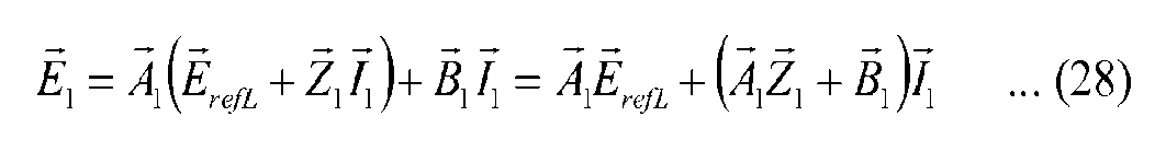
Cuando el circuito equivalente de la figura 9 se representa mediante la ecuación anterior, el circuito se puede describir como se muestra en la figura 13.When the equivalent circuit in figure 9 is represented by the above equation, the circuit can be described as shown in figure 13.
La figura 13 muestra la configuración que es básicamente la misma que la de la figura 3 descrita anteriormente. La figura 13 tiene una configuración diferente de la figura 3 en que, como fuente de tensión, un coeficiente Ai formado por una constante de circuito y una función de ganancia/transferencia de control se multiplica por un comando de tensión de carga ErefL. Figure 13 shows the configuration which is basically the same as that of Figure 3 described above. Fig. 13 has a different configuration from Fig. 3 in that, as a voltage source, a coefficient Ai formed by a circuit constant and a gain/control transfer function is multiplied by a load voltage command ErefL.
Además, la figura 13 es diferente de la figura 3 en que A iZ i + Bi está conectado como una impedancia equivalente en serie a la impedancia de la fuente de tensión y la carga.Also, Figure 13 is different from Figure 3 in that A iZ i + Bi is connected as an impedance equivalent in series to the impedance of the voltage source and the load.
La figura 14 es un diagrama que ilustra un circuito equivalente según la segunda realización.Fig. 14 is a diagram illustrating an equivalent circuit according to the second embodiment.
Como se muestra en la figura 14, cuando dos convertidores de salida de CA son iguales en función de ganancia/transferencia de control e impedancia del circuito en la configuración que se muestra en la figura 13, Zi = Z2, Ai = A2 = A, y Bi = B2 = B están establecidos.As shown in figure 14, when two AC output converters are equal as a function of gain/control transfer and circuit impedance in the configuration shown in figure 13, Zi = Z2, Ai = A2 = A, and Bi = B2 = B are established.
De manera similar a la descripción en la primera realización, también como en la segunda realización, la corriente compartida puede controlarse entre dos convertidores de salida de CA, de modo que la corriente pueda equilibrarse. Además, al mantener la relación de la siguiente ecuación con respecto a la impedancia del circuito y la función de ganancia/transferencia de control, la participación actual se puede establecer en una relación opcional h entre dos convertidores de salida de CA.Similar to the description in the first embodiment, as well as in the second embodiment, the shared current can be controlled between two AC output converters, so that the current can be balanced. Furthermore, by keeping the relationship of the following equation with respect to the impedance of the circuit and the gain/control transfer function, the current share can be set to an optional relationship h between two AC output converters.
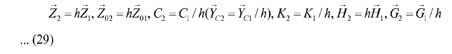
Cuando se establece esta relación, los coeficientes A2 y B2 del segundo convertidor de salida de CA se calculan.When this relationship is established, the coefficients A2 and B2 of the second AC output converter are calculated.

La ecuación (30) muestra que las magnitudes de las fuentes de tensión en los circuitos equivalentes de dos convertidores de salida de c A son iguales entre sí cuando se establece la relación de la ecuación (29).Equation (30) shows that the magnitudes of the voltage sources in the equivalent circuits of two c A output converters are equal to each other when the relationship in Equation (29) is established.
Además, la ecuación (31) muestra que la impedancia equivalente del segundo convertidor de salida de CA es h veces mayor que la del primer convertidor de salida de CA.Also, equation (31) shows that the equivalent impedance of the second AC output converter is h times greater than that of the first AC output converter.
La figura 15 es un diagrama que ilustra otro circuito equivalente según la segunda realización.Fig. 15 is a diagram illustrating another equivalent circuit according to the second embodiment.
Como se muestra en la figura 14, se establece la siguiente ecuación entre I1 y I2 cuando se establece la relación de la ecuación (28).As shown in Fig. 14, the following equation is established between I1 and I2 when the relationship of equation (28) is established.

En consecuencia, ajustando la impedancia del circuito y la función de ganancia/transferencia de control según corresponda, se puede ajustar la corriente compartida entre dos convertidores de salida de CA.Consequently, by adjusting the impedance of the circuit and the gain/control transfer function accordingly, the current sharing between two AC output converters can be adjusted.
La figura 16 es un diagrama que ilustra el resultado de la simulación del sistema de suministro de energía ininterrumpible 1# de acuerdo con la segunda realización.Fig. 16 is a diagram illustrating the simulation result of the uninterruptible power supply system 1# according to the second embodiment.
La figura 16 (A) muestra el valor efectivo y la fase de la fase representativa de la corriente de salida de cada uno de los convertidores de salida de CA 11A y 11B. Muestra que, después de que dos convertidores de salida de CA se inician en cero en el eje de tiempo, la participación actual se iguala en aproximadamente 0,3 segundos a 0,4 segundos. También muestra que la cuota actual se mantiene a partir de entonces incluso cuando la carga se reduce después de un lapso de 0,5 segundos o cuando la carga se cambia al valor original nuevamente después de un lapso de 0,8 segundos.Fig. 16(A) shows the effective value and the phase of the phase representative of the output current of each of the AC output converters 11A and 11B. It shows that after two AC output converters are started at zero on the time axis, the current share equalizes in about 0.3 seconds to 0.4 seconds. It also shows that the current quota is maintained thereafter even when the load is reduced after a lapse of 0.5 seconds or when the load is changed to the original value again after a lapse of 0.8 seconds.
La figura 16 (B) muestra el valor efectivo y la fase de la tensión de carga. Muestra que la tensión de la carga se mantiene a una tensión aproximadamente fijo en el estado estacionario, aunque ocurran fluctuaciones de la carga. En la presente simulación, dado que los convertidores de salida de CA 11A y 11B están provistos del mismo circuito de control de tensión del capacitor, estos convertidores de salida son operados por el mismo comando de tensión del capacitor. Por lo tanto, las tensiones de los capacitores en dos convertidores de salida de CA 11A y 11B se controlan para que sean iguales. Incluso si las corrientes de salida de dos convertidores de salida de CA 11A y 11B están desequilibradas debido a algunos factores, las corrientes de salida se controlan para equilibrarse finalmente.Figure 16(B) shows the effective value and phase of the charging voltage. It shows that the load voltage remains at an approximately fixed voltage in the steady state, even though load fluctuations occur. In the present simulation, since the AC output converters 11A and 11B are provided with the same capacitor voltage control circuit, these output converters are operated by the same capacitor voltage command. Therefore, the voltages of the capacitors in two AC output converters 11A and 11B are controlled to be equal. Even if the output currents of two AC output converters 11A and 11B are unbalanced due to some factors, the output currents are controlled to finally balance.
Además, la tensión en el bus conectado a la carga es información común a dos convertidores de salida de CA y también se puede detectar de forma independiente. Mediante la fase de referencia obtenida de esta manera, se pueden lograr las mismas funciones y efectos que los de la primera realización.In addition, the voltage on the bus connected to the load is common information to two AC output drives and can also be detected independently. By the reference phase thus obtained, the same functions and effects as those of the first embodiment can be achieved.
Por lo tanto, también en la presente realización, los convertidores de salida de CA pueden realizar el control utilizando solo las señales que pueden observar sus respectivos dispositivos, de modo que se puede controlar el equilibrio de corriente entre los convertidores de salida de c A. Además, dado que el control lo realizan únicamente los controladores incluidos en sus respectivos convertidores de salida de CA, se hace posible eliminar la necesidad de proporcionar: un controlador común a una pluralidad de convertidores de salida de CA; y los medios de transmisión/recepción de señales entre los convertidores de salida de CA.Therefore, also in the present embodiment, the AC output converters can perform control using only the signals that can be observed by their respective devices, so that the current balance between the AC output converters can be controlled. Furthermore, since the control is performed only by the controllers included in their respective AC output converters, it becomes possible to eliminate the need to provide: a controller common to a plurality of AC output converters; and the signal transmission/reception means between the AC output converters.
Primera Modificación de la Segunda RealizaciónFirst Modification of the Second Embodiment
La configuración que usa el reactor del lado de la carga en el filtro LCL como impedancia de salida se ha explicado en la descripción anterior. En este caso, incluso en la configuración que incluye un transformador provisto en lugar del reactor del lado de carga, la impedancia de cortocircuito (impedancia de fuga) del transformador de salida es equivalente a la del reactor, por lo que se puede lograr un efecto similar.The configuration using the load side reactor in the LCL filter as output impedance has been explained in the above description. In this case, even in the configuration that includes a transformer provided instead of the load-side reactor, the short-circuit impedance (leakage impedance) of the output transformer is equivalent to that of the reactor, so a positive effect can be achieved. similar.
La figura 17 es un diagrama que ilustra la configuración de un sistema de alimentación ininterrumpida 1#P según la primera modificación de la segunda realización.Fig. 17 is a diagram illustrating the configuration of an uninterruptible power supply 1#P according to the first modification of the second embodiment.
Como se muestra en la figura 17, el sistema de suministro de energía ininterrumpible 1#P es diferente del sistema de suministro de energía ininterrumpible 1# en que el convertidor de salida de CA 11A se reemplaza con un convertidor de salida de CA 11#PA mientras que el convertidor de salida de CA 11B se reemplaza con un convertidor de salida de CA 11#PB.As shown in Fig. 17, the 1#P uninterruptible power supply system is different from the 1# uninterruptible power supply system in that the 11A AC output converter is replaced with an 11#PA AC output converter. while the AC output converter 11B is replaced with an AC output converter 11#PB.
El convertidor de salida de CA 11#PA es diferente del convertidor de salida de CA 11A en que se elimina el reactor del filtro LCL 18A y se proporciona el transformador 18A en lugar del reactor. El detector de corriente 31A se proporciona entre el filtro y el transformador 18A. Dado que otras configuraciones son las mismas que las descritas en la figura 1, no se repetirá la descripción detallada de las mismas.The AC output converter 11#PA is different from the AC output converter 11A in that the LCL filter reactor 18A is eliminated and the transformer 18A is provided instead of the reactor. The 31A current detector is provided between the filter and the 18A transformer. Since other configurations are the same as those described in Fig. 1, the detailed description thereof will not be repeated.
Además, el convertidor de salida de CA 11#PB es diferente del convertidor de salida de CA 11B en que se elimina el reactor del filtro LCL 18B y se proporciona el transformador 18B en lugar del reactor. El detector de corriente 31B se proporciona entre el filtro y el transformador 18B. Dado que otras configuraciones son las mismas que las descritas en la figura 1, no se repetirá la descripción detallada de las mismas.In addition, the 11#PB AC output converter is different from the 11B AC output converter in that the LCL filter reactor 18B and transformer 18B is provided instead of the reactor. The current detector 31B is provided between the filter and the transformer 18B. Since other configurations are the same as those described in Fig. 1, the detailed description thereof will not be repeated.
La presente configuración también puede lograr el mismo efecto que en la primera realización. Además, el detector de corriente 31A se puede proporcionar entre la carga de CA 3 y el transformador 18A, mientras que el detector de corriente 31B se puede proporcionar entre la carga de CA 3 y el transformador 18B.The present configuration can also achieve the same effect as the first embodiment. Furthermore, the current detector 31A can be provided between the AC load 3 and the transformer 18A, while the current detector 31B can be provided between the AC load 3 and the transformer 18B.
Segunda Modificación de la Segunda RealizaciónSecond Modification of the Second Embodiment
La figura 18 es un diagrama que ilustra la configuración de un sistema de alimentación ininterrumpida 1#Q según la segunda modificación de la segunda realización.Fig. 18 is a diagram illustrating the configuration of an uninterruptible power supply 1#Q according to the second modification of the second embodiment.
Con referencia a la figura 18, el sistema de suministro de energía ininterrumpible 1#Q es diferente del sistema de suministro de energía ininterrumpible 1# en la figura 10 en que el convertidor de salida de CA 11A se reemplaza con un convertidor de salida de CA 11#QA mientras que el convertidor de salida de CA 11B se reemplaza con un convertidor de salida de CA 11#QB.Referring to Fig. 18, the uninterruptible power supply system 1#Q is different from the uninterruptible power supply system 1# in Fig. 10 in that the AC output converter 11A is replaced with an AC output converter. 11#QA while the 11B AC output converter is replaced with a 11#QB AC output converter.
El convertidor de salida de CA 11#QA es diferente del convertidor de salida de CA 11A en que la fase de referencia se obtiene de la tensión en el bus conectado a la carga 3. Dado que otras configuraciones son iguales, no se repetirá la descripción detallada de las mismas.The 11#QA AC output converter is different from the 11A AC output converter in that the reference phase is obtained from the voltage on the bus connected to load 3. As other settings are the same, the description will not be repeated. details of them.
Además, el convertidor de salida de CA 11#QB es diferente del convertidor de salida de CA 11B en que la fase de referencia se obtiene de la tensión en el bus conectado a la carga 3. Dado que otras configuraciones son iguales, no se repetirá la descripción detallada de las mismas. El mismo efecto que el de la primera realización se consigue también en la presente configuración.In addition, the 11#QB AC output converter is different from the 11B AC output converter in that the reference phase is obtained from the voltage on the bus connected to load 3. Since other settings are the same, it will not be repeated. their detailed description. The same effect as that of the first embodiment is also achieved in the present configuration.
El mismo efecto que el de la segunda realización se consigue también en la presente configuración.The same effect as that of the second embodiment is also achieved in the present configuration.
Además, la tensión en el bus conectado a la carga también se considera como información que es común a dos convertidores de salida de CA y que es detectable por dos convertidores de salida de CA de forma independiente. En consecuencia, se puede lograr el mismo efecto que en la segunda realización.In addition, the voltage on the bus connected to the load is also considered as information that is common to two AC output drives and detectable by two AC output drives independently. Accordingly, the same effect as in the second embodiment can be achieved.
Tercera RealizaciónThird Realization
La figura 19 es un diagrama que muestra esquemáticamente la configuración de un sistema de suministro de energía ininterrumpible según la tercera realización.Fig. 19 is a diagram schematically showing the configuration of an uninterruptible power supply system according to the third embodiment.
La figura 19 muestra esquemáticamente el caso en el que se aplican tres convertidores de salida de CA diferentes. Por ejemplo, se describirá el caso en el que se proporcionan convertidores de salida de CA 11A, 11B y 11C.Fig. 19 schematically shows the case where three different AC output converters are applied. For example, the case where AC output converters 11A, 11B and 11C are provided will be described.
El presente ejemplo muestra una configuración en la que tres convertidores de salida de CA 11A, 11B y 11C tienen una capacidad diferente entre sí, y las impedancias del reactor del lado de carga L1 en el filtro LCL 18 se definen como Zi, Z2 y Z3. The present example shows a configuration where three AC output converters 11A, 11B and 11C have a different capacitance from each other, and the impedances of the load side reactor L1 in the LCL filter 18 are defined as Zi, Z2 and Z3 . .
Por ejemplo, a continuación, se dará una explicación con respecto al caso en el que la relación de impedancia de los convertidores de salida de CA 11A, 11B y 11C se establece en Z 1.Z2.Z3 = 1:1,25 :1,5 y también el caso en el que la relación de las funciones de transferencia se ajusta de manera similar.For example, below, an explanation will be given regarding the case where the impedance ratio of the AC output converters 11A, 11B and 11C is set to Z 1.Z2.Z3 = 1:1.25:1 ,5 and also the case where the ratio of the transfer functions fits in a similar way.
La figura 20 es un diagrama que ilustra el resultado de la simulación de un sistema de suministro de energía ininterrumpible 1# según la tercera realización.Fig. 20 is a diagram illustrating the simulation result of a 1# uninterruptible power supply system according to the third embodiment.
Como se muestra en la figura 20, se confirmó que, en esta configuración, la relación de las corrientes de salida de los convertidores de salida de CA 11A, 11B y 11C es inversamente proporcional a la relación de impedancia y se controla para que sea ir.h ih = 1,5:1,25:1.As shown in Fig. 20, it was confirmed that in this configuration the ratio of the output currents of the AC output converters 11A, 11B and 11C is inversely proportional to the impedance ratio and is controlled to be ir .h ih = 1.5:1.25:1.
Por lo tanto, también en la presente realización, los convertidores de salida de CA pueden realizar el control usando solo las señales que pueden observar sus respectivos dispositivos, de manera que se puede controlar el equilibrio de corriente entre los convertidores de salida de CA.Therefore, also in the present embodiment, the AC output converters can perform control using only the signals that can be observed by their respective devices, so that the current balance between the AC output converters can be controlled.
Además, incluso cuando los valores de las impedancias de los reactores del lado de la carga en los convertidores de salida de CA son diferentes, los valores de comando de tensión se producen en consecuencia, de modo que la corriente puede controlarse para distribuirse de acuerdo con cada uno de los convertidores de salida de CA incluso en el caso de que los convertidores de salida de CA que tengan diferentes capacidades estén dispuestos en paralelo. Furthermore, even when the values of the impedances of the load-side reactors in the AC output converters are different, the voltage command values are produced accordingly, so that the current can be controlled to distribute according to each of the AC output converters even in the case that the AC output converters having different capacities are arranged in parallel.
LISTA DE SEÑALES DE REFERENCIALIST OF REFERENCE SIGNS
1, 1P, 1#, 1#P sistema de alimentación ininterrumpida, 2 fuente de alimentación CA, 3 cargas, 10, 10A, 10B, 11, 11A, 11B convertidor de salida CA, 12A, transformador 12B, 14A, rectificador 14B, 15A, Condensador de CC 15B, convertidor PWM 16A, 16B, impedancia de salida 17A, 17B, filtro LCL 18A, 18B, controlador 20A, 20B, 50A, 50B, detector de tensión 21A, 21B, 53A, 53B, circuito de generación de señal de fase de referencia 22A, 22B, 23A, 23B función de transformación dq, 24A, 24B, 60 multiplicador vectorial, 25A, 25B función de ganancia, 26A, 26B, 70 sumador vectorial, 27A, 27B, 92 función de transformación inversa dq, 28A, 28B, 93 generador de impulsos PWM, 29A, 29B, 30A, 30B, 56A, registro 56B, detector de corriente 31A, 31B, 54A, 54B, circuito de generación de valor de comando de tensión de condensador 52A, 52B, circuito de control de tensión de condensador 55A, 55B. 1, 1P, 1#, 1#P uninterruptible power supply, 2 AC power supply, 3 loads, 10, 10A, 10B, 11, 11A, 11B AC output converter, 12A, transformer 12B, 14A, rectifier 14B, 15A, DC capacitor 15B, PWM converter 16A, 16B, output impedance 17A, 17B, LCL filter 18A, 18B, driver 20A, 20B, 50A, 50B, voltage detector 21A, 21B, 53A, 53B, generation circuit reference phase signal 22A, 22B, 23A, 23B dq transform function, 24A, 24B, 60 vector multiplier, 25A, 25B gain function, 26A, 26B, 70 vector adder, 27A, 27B, 92 dq inverse transform function , 28A, 28B, 93 PWM pulse generator, 29A, 29B, 30A, 30B, 56A, register 56B, current detector 31A, 31B, 54A, 54B, capacitor voltage command value generation circuit 52A, 52B, capacitor voltage control circuit 55A, 55B.
Claims (9)
Applications Claiming Priority (1)
| Application Number | Priority Date | Filing Date | Title |
|---|---|---|---|
| PCT/JP2016/077129 WO2018051433A1 (en) | 2016-09-14 | 2016-09-14 | Power supply system |
Publications (1)
| Publication Number | Publication Date |
|---|---|
| ES2944136T3 true ES2944136T3 (en) | 2023-06-19 |
Family
ID=61619887
Family Applications (1)
| Application Number | Title | Priority Date | Filing Date |
|---|---|---|---|
| ES16916217T Active ES2944136T3 (en) | 2016-09-14 | 2016-09-14 | power supply system |
Country Status (6)
| Country | Link |
|---|---|
| US (1) | US10581338B2 (en) |
| EP (1) | EP3514942B1 (en) |
| JP (1) | JP6802278B2 (en) |
| CN (1) | CN109716641B (en) |
| ES (1) | ES2944136T3 (en) |
| WO (1) | WO2018051433A1 (en) |
Families Citing this family (3)
| Publication number | Priority date | Publication date | Assignee | Title |
|---|---|---|---|---|
| DE102019106257A1 (en) * | 2019-03-12 | 2020-09-17 | Sma Solar Technology Ag | Battery inverter system |
| CN113612402A (en) * | 2021-08-09 | 2021-11-05 | 山特电子(深圳)有限公司 | Three-phase inversion control system and control method |
| EP4687271A1 (en) * | 2024-07-31 | 2026-02-04 | Abb Schweiz Ag | Current sharing of parallel-connected converters |
Family Cites Families (17)
| Publication number | Priority date | Publication date | Assignee | Title |
|---|---|---|---|---|
| JP2679411B2 (en) | 1990-12-19 | 1997-11-19 | 三菱電機株式会社 | Parallel operation control device for AC output converter |
| JPH08280192A (en) * | 1995-04-07 | 1996-10-22 | Meidensha Corp | Method and device for operating inverters in parallel |
| JPH09331682A (en) * | 1996-06-12 | 1997-12-22 | Meidensha Corp | Power converter |
| JP3389072B2 (en) * | 1997-09-05 | 2003-03-24 | 芝府エンジニアリング株式会社 | Power converter |
| JP3590735B2 (en) * | 1999-03-15 | 2004-11-17 | 東芝三菱電機産業システム株式会社 | Control circuit of power converter |
| JP3797879B2 (en) * | 2001-02-14 | 2006-07-19 | 財団法人鉄道総合技術研究所 | PWM converter controller with zero-phase current control function |
| JP4664836B2 (en) * | 2006-02-28 | 2011-04-06 | オリジン電気株式会社 | Three-phase voltage type AC / DC converter |
| JP2009022094A (en) * | 2007-07-11 | 2009-01-29 | Fuji Electric Systems Co Ltd | Three-phase AC-AC converter |
| JP5217397B2 (en) * | 2007-12-04 | 2013-06-19 | 富士電機株式会社 | Parallel operation control system for power converter |
| JP5453729B2 (en) * | 2008-04-14 | 2014-03-26 | 株式会社ジェイテクト | Motor control device and electric power steering device |
| US8379416B1 (en) * | 2011-08-29 | 2013-02-19 | General Electric Company | Power conversion system and method |
| JP6058884B2 (en) * | 2011-11-15 | 2017-01-11 | 株式会社コンピュータシステム研究所 | Building quality evaluation apparatus, method, program and storage medium |
| JP5803681B2 (en) * | 2012-01-12 | 2015-11-04 | 株式会社明電舎 | PWM power converter parallel operation device |
| CN103280999B (en) * | 2013-04-24 | 2015-06-10 | 浙江大学 | Multi-module inverter wired parallel digital control method |
| JP6397613B2 (en) * | 2013-09-27 | 2018-09-26 | 株式会社ダイヘン | Control circuit for controlling inverter circuit, inverter device provided with the control circuit, power system provided with the inverter device, and control method |
| JP6586723B2 (en) * | 2014-10-15 | 2019-10-09 | 株式会社明電舎 | Method for suppressing cross current of power converter |
| CN104466963A (en) * | 2014-12-11 | 2015-03-25 | 湖南大学 | Power induction and regulation filtering device and control method thereof |
-
2016
- 2016-09-14 WO PCT/JP2016/077129 patent/WO2018051433A1/en not_active Ceased
- 2016-09-14 US US16/331,877 patent/US10581338B2/en active Active
- 2016-09-14 ES ES16916217T patent/ES2944136T3/en active Active
- 2016-09-14 EP EP16916217.9A patent/EP3514942B1/en active Active
- 2016-09-14 JP JP2018539007A patent/JP6802278B2/en active Active
- 2016-09-14 CN CN201680089270.1A patent/CN109716641B/en active Active
Also Published As
| Publication number | Publication date |
|---|---|
| JP6802278B2 (en) | 2020-12-16 |
| EP3514942A4 (en) | 2020-04-29 |
| CN109716641B (en) | 2021-05-04 |
| EP3514942A1 (en) | 2019-07-24 |
| WO2018051433A1 (en) | 2018-03-22 |
| CN109716641A (en) | 2019-05-03 |
| JPWO2018051433A1 (en) | 2019-06-27 |
| EP3514942B1 (en) | 2023-03-08 |
| US10581338B2 (en) | 2020-03-03 |
| US20190214918A1 (en) | 2019-07-11 |
Similar Documents
| Publication | Publication Date | Title |
|---|---|---|
| He et al. | Inverse power factor droop control for decentralized power sharing in series-connected-microconverters-based islanding microgrids | |
| US9048754B2 (en) | System and method for offsetting the input voltage unbalance in multilevel inverters or the like | |
| US10560036B2 (en) | Power conversion device for reliable control of circulating current while maintaining voltage of a cell | |
| JPWO2017046908A1 (en) | Power converter | |
| JP5984916B2 (en) | Power converter | |
| WO2017046909A1 (en) | Power conversion device | |
| JPWO2015102049A1 (en) | Power converter | |
| ES2944136T3 (en) | power supply system | |
| JP6276370B2 (en) | Hybrid power supply | |
| CN115989625A (en) | Method for operating a converter, converter and computer program product | |
| Golestan et al. | Droop based control of parallel-connected single-phase inverters in DQ rotating frame | |
| Jakka et al. | A triple port active bridge converter based multi-fed power electronic transformer | |
| Shi et al. | Adaptive implementation strategy of virtual impedance for paralleled inverters UPS | |
| Wei et al. | Control architecture for paralleled current-source-inverter (CSI) based uninterruptible power systems (UPS) | |
| Etxeberria et al. | Control of a vanadium redox battery and supercapacitor using a three-level neutral point clamped converter | |
| Arani et al. | Improving power sharing and reduction circulating current in parallel inverters of isolated microgrids | |
| Chitra et al. | Design and implementation of maximum constant boost switched inductor z-source inverter for three-phase on-line uninterrupted power supply | |
| JP2017225214A (en) | Parallel operation control method and parallel operation control device for three-phase inverter | |
| WO2021124577A1 (en) | Power conversion device | |
| Song et al. | Circulating current elimination scheme for parallel operation of common dc bus inverters | |
| KR101696510B1 (en) | Inverter controlling system for compensating distortion of output voltage | |
| Singh et al. | PV-battery based single phase microgrid with grid synchronization and de-synchronization capabilities | |
| Brychcín et al. | Modulator for 4-level flying capacitor converter with balancing control in the closed loop | |
| Alhosaini et al. | Fast and Secure Operation of Voltage Source Inverter based DERs using Model Predictive Droop Control | |
| JP6851895B2 (en) | Power converter |